

TYAN Thunder i860 S2603, Thunder i860, S2603 User Manual

TM
Thunder i860
S2603
User’s Manual
Revision 1.00
Copyright © Tyan Computer Corporation, 2001. All rights reserved. No part of this
manual may be reproduced or translated without prior written consent from Tyan
Computer Corp.
All registered and unregistered trademarks and company names contained in this
manual are property of their respective owners including, but not limited to the following.
Tyan, Thunder i860 S2603 are trademarks of Tyan Computer Corporation.
Intel, Xeon, 860 chipset are trademarks of Intel Corporation.
Rambus is a trademark of Rambus Inc.
Phoenix, Phoenix BIOS are trademarks of Phoenix Software.
Microsoft, Windows are trademarks of Microsoft Corporation.
IBM, PC, AT, PS/2 are trademarks of IBM Corporation.
QLogic, Zircon are trademarks of QLogic Corporation.
Winbond is a trademark of Winbond Electronics Corporation.
National is a trademark of National Semiconductor Corporation.
Information contained in this document is furnished by Tyan Computer Corporation and has been reviewed for accuracy and reliability prior to printing. Tyan
assumes no liability whatsoever, and disclaims any express or implied warranty,
relating to sale and/or use of Tyan products including liability or warranties relating
to fitness for a partic ular pu rpose o r merch antabi lity. Tyan retains the right to mak e
changes to product descriptions and/or specifications at any time, without notice.
In no event will Tyan be held liable for any direct or indirect, incidental or consequential damage, loss of use, loss of data or other malady resulting from errors or
inaccuracies of information contained in this document.

Table of Contents
Chapter 1: Introduction
1.1
1.2
1.3
1.4
1.5
Overview ....................................................................................................................4
Hardware Specifications ............................................................................................5
Software Specifications ..............................................................................................6
Technical Support ......................................................................................................7
Returning Merchandise for Service ............................................................................7
.............................................................
Chapter 2: Board Installation
2.1
2.2
2.3
2.4
2.5
2.6
2.6-A
2.6-B
2.6-C
2.6-D
2.6-E
2.6-F
2.6-G
2.6-H
2.6-I
2.6-J
2.6-K
2.6-L
2.7
2.8
2.9
2.10
2.11
2.12
2.13
2.14
Unpacking ..................................................................................................................8
Installation ..................................................................................................................8
How to install our products right... the first time ..........................................................8
Quick Reference for Jumpers ..................................................................................10
Map of Motherboard Jumpers ..................................................................................11
Setting up Jumpers and Onboard Connectors .........................................................12
Front Panel Connector .............................................................................................12
CMOS Reset ............................................................................................................12
BIOS Boot Block ......................................................................................................13
DIP Switch ...............................................................................................................13
Onboard LAN Enable/Disable ..................................................................................14
Onboard SCSI Enable/Disable .................................................................................14
Speaker Connector ................................ ................................ ..................................15
PCI Speed Select .....................................................................................................15
FAN Connectors ............................... ..... ...... ............................... ..... ........................16
Soft Power Connector ..............................................................................................16
Hardware Reset Switch Connector Installation ........................................................16
Flash Utility ....................... ...... ..... ............................... ...... ............................... ........16
Mounting the Motherboard in the Chassis ................................................................17
Installing Memory .....................................................................................................18
Installing the CPU and Cooling Fan(s) .....................................................................23
Connecting IDE and Floppy Drives ..........................................................................25
Installing Add-on Cards ............................................................................................27
About the AGP Pro slot ............................................................................................28
Connecting PS/2, USB, and Serial Devices .............................................................29
Connecting the Power Supply ..................................................................................30
Frequently Asked Questions (FAQ) .........................................................................32
Page 4
.............................................................
8
Chapter 3: BIOS Setup
Introduction to the BIOS Setup .................................................................................33
Starting Setup .............. ..... ...... ............................... ................................ ..................33
Setup Keys ...............................................................................................................34
Getting Help .............................................................................................................34
In Case of Problems .................................................................................................34
Setup Variations ................................ ..... ...... ..... ..... ..... ...... ............................... ........34
2
....................................................................
http://www.tyan.com
33

3.2-A
3.2-B
3.2-C
3.2-D
3.2-E
3.2-F
3.2-G
3.2-H
3.2-I
3.2-J
3.3
3.4
3.5
3.6
Main Setup ................... ..... ...... ..... ............................... ................................ .............353.1
Advanced Setup .......................................................................................................363.2
Processors screen ..................................................................................................36
Chipset screen .........................................................................................................37
Floppy Disk Drive screen .........................................................................................37
IDE Devices screen ..................................................................................................38
Integrated SCSI screen ............................................................................................40
Integrated Network screen ...... ..... ..... ..... ................................ ............................... ...40
Integrated I/O Ports screen ......................................................................................41
Integrated Audio screen ...........................................................................................42
AGP Slot (Graphics) screen .....................................................................................42
PCI Device, Slot #1 (...2, 3, 4, 5) screen ..................................................................43
Security Setup ..........................................................................................................43
Power Setup ............................................................................................................45
Boot Setup ................... ..... ...... ..... ..... ..... ...... ............................... .............................45
Exit Setup .................................................................................................................46
Chapter 4: System Resources
4.1
4.2
Beep Codes .............................................................................................................47
Flash Utility ....................... ...... ..... ............................... ...... ............................... ........47
.......................................................
Appendix I: SCSI Installation and LAN Information 48......................
Introduction ..............................................................................................................48
Features of the LSI Symbios SCSI BIOS .................................................................48
Legacy Support for non-Ultra160 SCSI devices .......................................................48
Setting up internal SCSI peripherals ........................................................................48
Checking SCSI IDs ..................................................................................................48
Terminating SCSI devices ........................................................................................48
Connecting SCSI Peripherals ..................................................................................48
Connecting internal cables for Ultra160 LVD SCSI devices .....................................48
Information on the LSI Symbios 53C1010 SCSI BIOS .............................................50
Boot Initialization with BIOS Boot Specification (BBS) .............................................50
CD-ROM Boot Initialization ......................................................................................50
Starting the SCSI BIOS Configuration Utility ............................................................50
Error Messages ........................................................................................................51
Using the Configuration Utility ..................................................................................51
Main Menu ...............................................................................................................52
Boot Adapter List ......................................................................................................53
Global Properties .....................................................................................................54
Adapter Propert ies ....... ..... ...... ............................... ..................................................55
Device Properties .....................................................................................................57
Quitting the SCSI BIOS Configuration Utility ............................................................58
LAN Information .......................................................................................................59
47
Appendix II: Glossary
Thunder i860 S2603
60.......................................................................
3

Chapter 1: Introduction
1.1 Congratulations!
You are now the proud owner of the premier dual Intel® Xeon™ platform!
The Thunder i860™ is a high performance workstation platform designed for applications that require the
power of dual Intel® Xeon™ processors. This platform utilizes the Intel 860 chipset and can support CPU
speeds through 1.7+GHz* and front side bus speeds of 100 MHz or 133 MHz. Please see Tyan’s website
for updates and information concerning CPU information and support:
http://www.tyan.com
This integrate d performance bo ard is suppo rted in an Ext ended ATX form factor. Some of the f eatures
included are onboard UltraDMA-100/66/33 support, and an Intel 82550 10/100 LAN controller.
With I/O and drive controller support onboard, the one 4X AGP Pro 50 slot, three 32-bit/33MHz PCI slots,
and two 64/32-bit 66/33MHz PCI slots are free for numerous types of add-on expansion cards. The use of
a separate Memory Expansion Card (MEC) allows for memory expansion options.
Remember to visit Tyan’s website at http://www.tyan.com. There you can find information on all of
Tyan’s products with FAQs, distributors list, and BIOS settings explanations.
NOTE: Due to its extr em ely pow erfu l pr oc ess in g cap ab ili tie s, th e Th un de r i860 re qu ir es a spec ialized dual Xeon-capable, APPROVED* power supply. Also, a Memory Expansion Card (MEC) is
required to harness the complete Rambus memory performance potential.
* not verified at time of print, check the Tyan website for updates: http://www.tyan.com
4
http://www.tyan.com

1.2 Hardware Specifications
Processor Information
Expansion Slots
Chipset Information
Hardware Monitoring
Memory
Integrated I/O
Dual PGA603 ZIF sockets
Supports dual Intel Xeon processors
One onboard VRM
400MHz system bus support
One 4X AGP Pro 50 slot supports 2x/4x modes
Three 32-bit 33MHz PCI slots
Two 64/32-bit 66/33MHz 3.3V PCI slots
Total of six usable slots
Intel 860 chipset
MCH+ICH2+FWH
National PC87366 Super I/O ASIC
Winbond 83782D hardware monitoring chip
3-pin fan monitoring headers
CPU temperature and voltage monitoring
Eight 168-pin Rambus RIMM sockets (on MEC)
Supports up to 2GB* PC800 Registered RDRAM
Supports ECC (72-bit) memory modules
One floppy connector supports up to two drives
Two 9-pin 16550-based serial ports
One 25-pin SPP/ECP/EPP parallel port
Two USB po rts
PS/2 keyboard and mouse ports
Integrated PCI IDE
Integrated LAN
Integrated SCSI
(manufacturing option)
Integrated Audio
(manufacturing option)
Dual-channel master mode
Up to four Enhanced IDE devices
Support for UltraDMA-100/66/33 IDE and ATAPI compliant devices
Intel 82550 LAN controller
10/100 Mbps data transfer rate capability
LSI Symbios 53C1010R controller
Dual-channel Ultra160 SCSI support
160Mbps maximum data thr oug hput
Supports up to 15 LVD SCSI devices per channel
Channels 1 & 2: 68-pin connector each
AD1885 chipset
AC’97 codec
Line-in, line-out, and mic-in ports
* Not validated at time of print, please check Tyan website for memory compatibility information:
http://www.tyan.com
Thunder i860 S2603
5

BIOS
Phoenix BIOS 2 Mbit Flash
Supports APM 1.2 & ACPI 1.0
Auto-configuration of IDE hard disk types
Multiple boot options
DMI 2.0 compliant
Form Factor
Regulatory
1.3 Software Specifications
OS
Ext. ATX 12” x 13” (304.80mm x 330.20mm)
One 24-pin and one 8-pin power connector
Stacked mouse & keyboa rd ports
Stacked two USB ports
Stacked one parallel and two serial ports
One RJ-45 LAN port with LEDs
FCC Class B (Declaration of Conformity)
European Community CE (Declaration of Conformity)
Windows NT/2000
6
http://www.tyan.com

1.4 Technical Support
If a problem arises with your system, you should turn to your dealer for help first. Your system has most
likely been config ured by them , and they sh ould have the be st idea of what hardw are and so ftware your
system contains. Hence, they sh ou ld be of the mo st assist ance. Furthermore, if you p urch ased you r system from a dealer n ear you, you can a ctually bring your syste m to them to have it serviced, instead of
attempting to do so yourself (which can have expensive consequences).
Help Resources:
1. See the FAQ and beep codes section of this manual.
2. See the Tyan website for FAQ, bulletins, driver updates, and other
information: http://www.tyan.com
3. Contact your dealer for help BEFORE calling Tyan.
4. Check the Tyan user group: alt.comp.periphs.mainboard.tyan
1.5 Returning Merchandise for Service
During the warrant y period, contact you r distributor or syste m vendor FIRST for any product p roblems.
This warranty only cove rs no rm al cust ome r use and does n ot cove r da mag es incu rr ed du ring shi pp ing or
failure due to the alteration, misuse, abuse, or improper maintenance of products.
NOTE: A receipt or co py o f your invoice mark ed wit h the date o f purch ase is requ ired befo re any
warranty service can be rendered. You may obtain service by calling the manufacturer for a
Return Merchan dise Authorization (RMA) number. The RMA number sho uld be prominently displayed on the o ut sid e of the shipp i n g ca rton an d th e p ack ag e sh ou ld be m ail ed prep aid . Tyan will
pay to have the board shipped back to you.
Thunder i860 S2603
7

Chapter 2: Board Installation
2.1 Unpacking
The retail motherboard package should contain the following:
Thunder i860 motherboard
Memory Expansion Card (MEC)
(2) Continuity RIMMs
34-pin floppy cable
UltraDMA-100/66/33 IDE cable
68-pin Ultra160 LVD SCSI cable
I/O shield*
Thunder i860 user’s manual
Tyan driver CD
(2) LSI SYM1010 SCSI Driver Disks
2.2 Installation
You are no w ready to install you r motherboar d. The mounting hole pattern of th e motherboar d matches
the ATX board specifications, so your chassis m ust be capable of supporting an Ex tended ATX bo ard
(check the motherboard dimensions provided on p. 6).
2.3 How to install our products right.. the first time.
Question: what’s the first thing I should do?
The first thing you should do is read the user’s manual. It contains important info rmation wh ich will make
configuration and setup much easier, as well as provide information on device installation and component
set up. By reading through the manual com pletely before installing your motherboard, you will have a
complete overview on the installation.
* if you require a different I/O shield solution, please contact your chassis vendor
8
http://www.tyan.com

Here are some safety tips:
(1) Ground yourself properly before removing your motherboard from the antistatic bag. Unplug
the power from your computer power supply and touch any metal part on the computer case. (You
might also want to wear a grounded wrist strap.)
(2) Hold the motherboard by its edges and do not touch the bottom of the board.
(3) Avoid touching motherboard components, IC chips, connectors, and leads.
(4) Avoid touching pins of memory modules and chips.
(5) Place motherboard on a grounded antistatic surface or on the antistatic bag.
Having reviewed the precautions above, the next step is to take the motherboard out of the cardboard box
and static bag, hold it by its edges, an d place it on a ground ed antistatic surface, component side up.
Inspect the board for damage.
NOTE: DO NOT APPLY POWER TO THE BOARD IF IT HAS BEEN DAMAGED!
Press down on any of the socketed ICs if it appears that they are not properly seated (the board should
still be on an antistatic mat). Do not touch the bottom of the board. Remember, don’t take any electronic
device out of its protective bag until you are ready to actually install it into the computer case. If you do not
ground yourself, you risk zapping the motherboard or adapter card. Subsequent problems may not arise
immediately because electrostatic discharge, unlike physical damage, causes the device to fail over time.
Thunder i860 S2603
9
2.4 Quick References for Jumpers
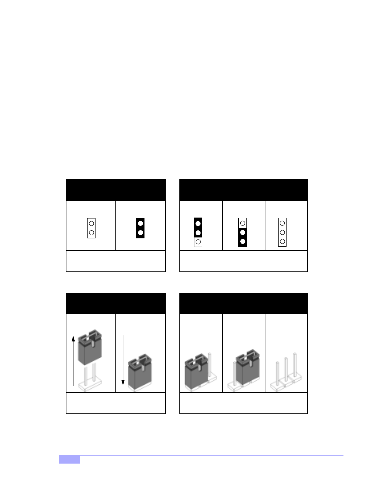
In this manual, the term “closed” and “on” are used when referring to jump ers (or jumper pins) th at are
active; “open” a nd “off” a re u sed whe n re fer ri ng to ju mp ers (or jumper pin s) th at a re in act ive. S ee Figure
2.0a and Figure 2.0c for examples of “on” and “off” pins and jumpers.
Jumpers and pins are con nected by slipping the plasti c jumper connector over the top of two adjacent
jumper pins ( indicated by 1- 2 or 2-3). The met al rod inside t he plastic sh ell b ridges the ga p betw een the
two pins, completin g the circuit. See Figure 2 .0b and Figure 2.0d for more examples of 3-pin jumper
connections. NOTE: The small number “1” indicates pin 1.
The tables and maps on the following p ages will help you set the jum pers for CPU speed, infr ared, and
external connector pin assignments, among others. The miniature motherboard maps will help you locate
the jumpers on your board. Full page maps of the motherboard can be found on the next two pages.
2-pin jumpers
off on
Figure 2.0a
(overhead view)
1-2 2-3 open
3-pin jumpers
1
2
3
Figure 2.0b
(overhead view)
1
2
3
2-pin jumpers 3-pin jumpers
1-2 2-3 openoff on
1
2
3
Figure 2.0c
(front angle view)
10
11
Figure 2.0d
(front angle view)
http://www.tyan.com
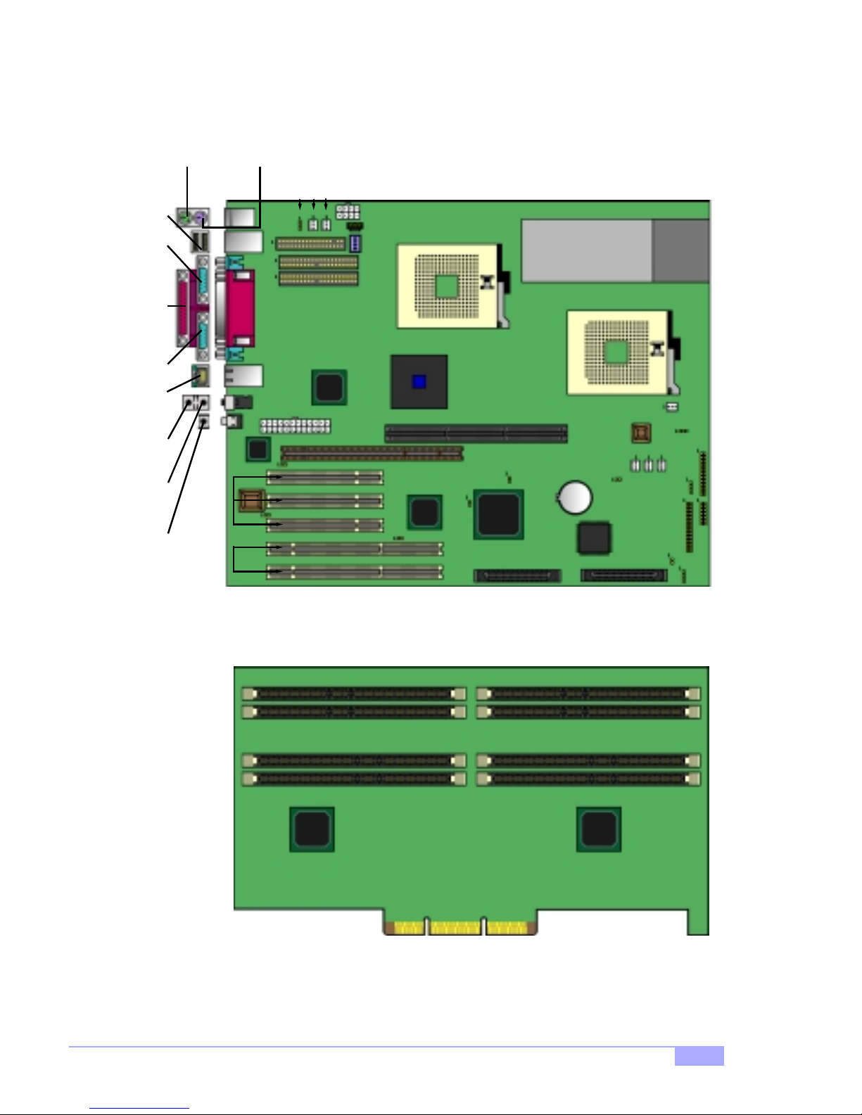
2.5 Map of Motherboard Jumpers
Mouse por t
(upper port)
USB
Ports
Serial
port 1
port
Parallel
Serial
port 2
port
LAN
Line-in*Line-out*Mic-in*
(2) 64/32-bit
Keyboard port
(lower port)
Intel
82550
(3) 32-bit
PCI slots
PCI slots
66/33MHz
FDD
24-pin power
J43
Connector
connector
J28
J59
J34
8-pin power
connector
J33
AUD CD
J26**
JBC2
JBC1
Processor 1 (P1)
Intel
i860
AGP Pro 4X Slot
J25
MEC Slot
J51
53C1010R
LSI
SCSI*
J50
Processor 0 (P0)
Battery
J13
SCSI CH. 1*SCSI CH. 2*
J36*
J32
J20
J35
J37
J12
ITP
J49
J24
J23
* indicates an optional feature available on some Thunder i860 models
** J26 (dip switch), if present on the Thunder i860, must always have positions 1 through 4 switched to
“OFF” (in the bottom position). Details on p.13.
Thunder i860 S2603
Memory Expans ion Card (MEC)
11
2.6 Setting up Jumpers and Onboard Connectors
Pinouts for certain connectors are available on the Tyan website: http://www.tyan.com
Pinouts for certain connectors are available on the Tyan website: http://www.tyan.com
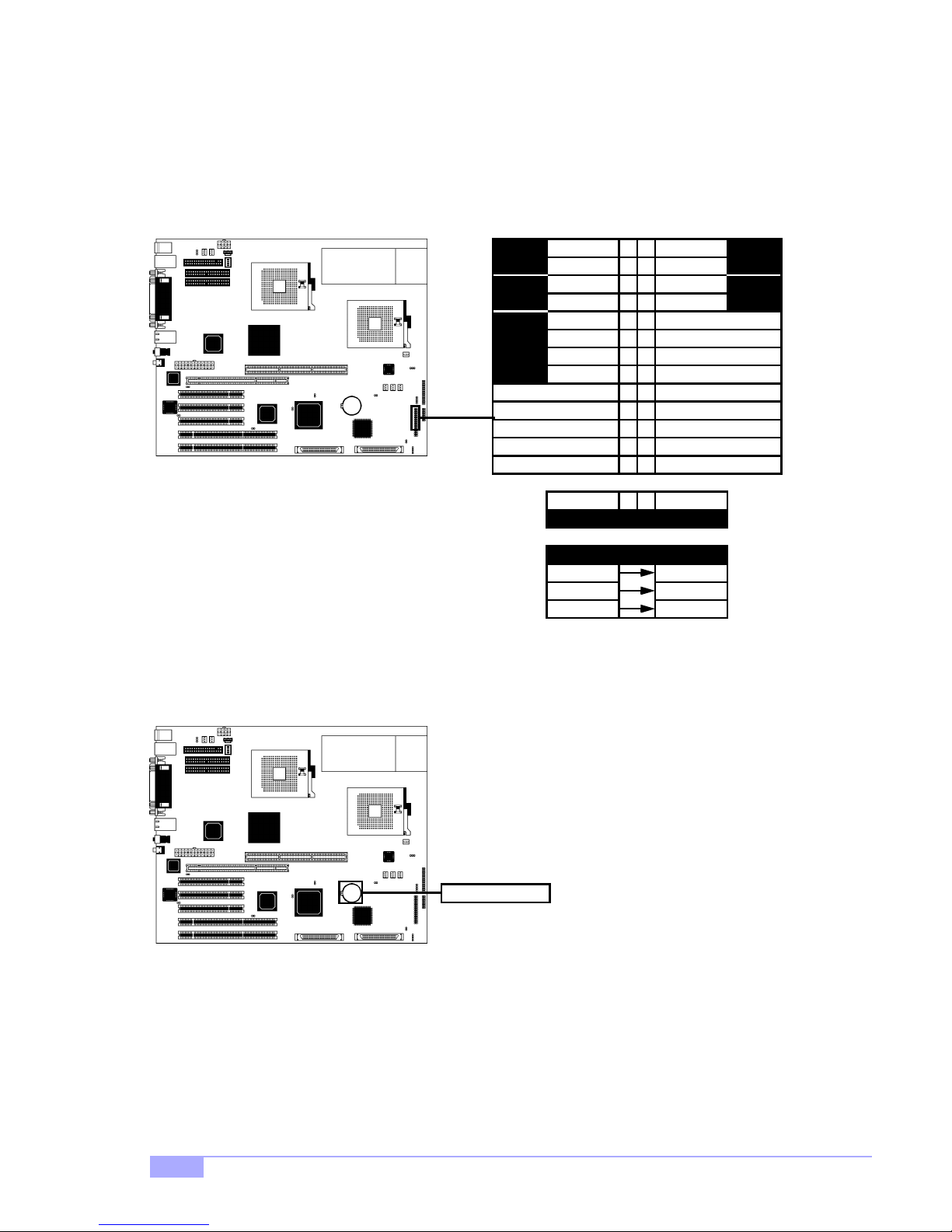
A. Front Panel Connector (J24)
Your chassis will usually come with connectors to install onto
the motherboard, such as HDD and Power LEDs. The Front
Panel Connector has been implemented for such purposes.
B. CMOS Reset (Battery)
LED
HDD
Sw
Rst
Infrared
VCC
LED
ground
switch 7 8
IR +5V
IR RX
ground
IR TX
Pwr Power
Slp Sleep
12
Pwr LED+
Slp LED+
34
5
6
ground
10
9
12
11
14
13
151716
18
1920
2122
2324
2526
LAN LED
Abbreviations
switch
LEDVCC 27 28
ResetRst
Pwr
LED
Sw
Pwr
If you have been locked out o f your system beca use you forgot your password or set the CMOS incorrectly, or have just finished flashing your BIOS follow the instructions below.
1. Power off the system, and disconnect the power supply
2. Pop out (uninstall) the battery by pressing on the rear latch
3. Wait about FIVE seconds
4. Re-install the battery, then power on the system again
By following this procedure, you will erase your password and reset the CMOS.
12
CMOS Battery
http://www.tyan.com
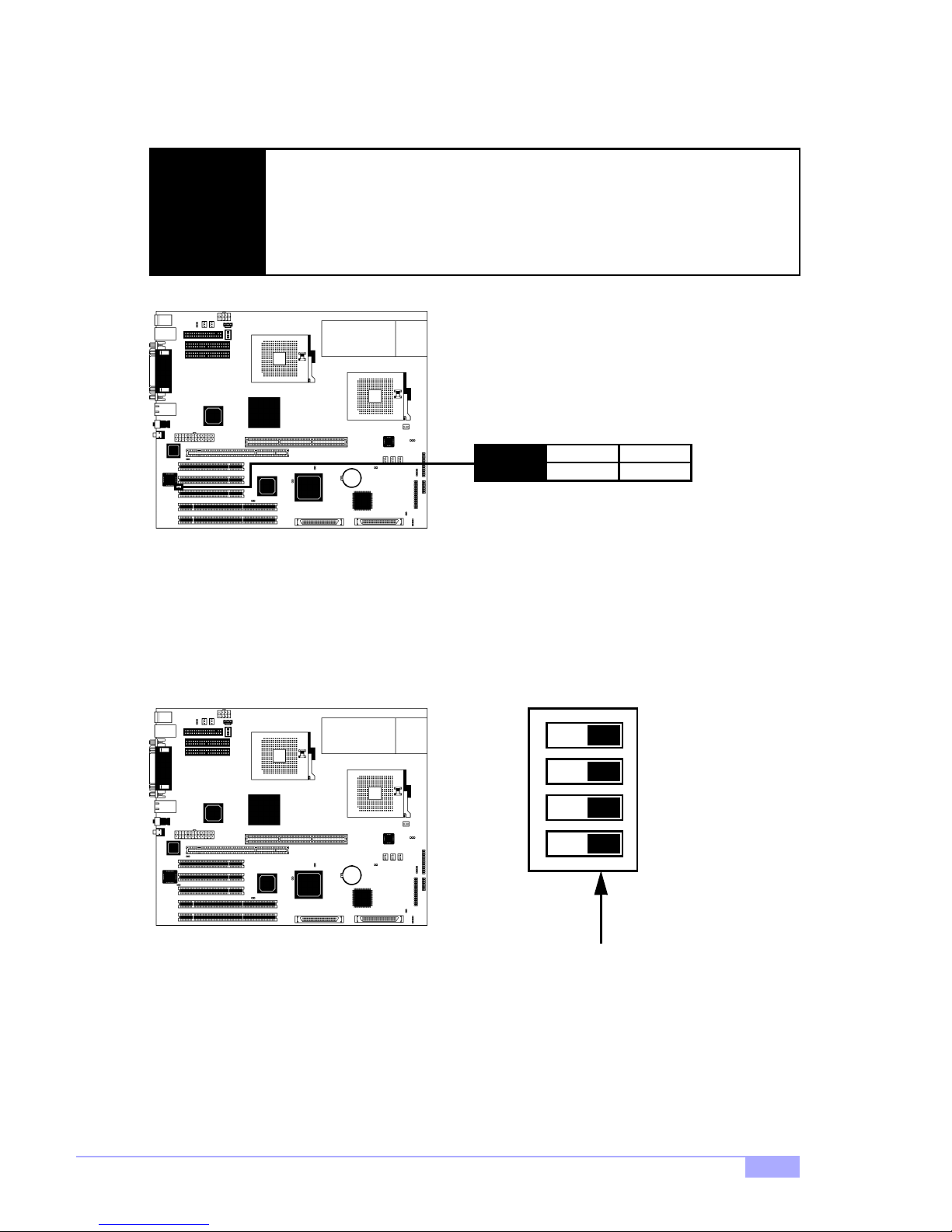
C. BIOS Boot Block (J43)
In case there is an error during flashing, the BIOS Boot Block provides a protection feature for the BIOS.
DO NOT alter this jumper unless you are absolutely sure you fully understand this
jumper’s effects on your system.
NOTE:
Tyan takes no reponsibility and will not be held liable for damage related to a lteration of this jumper from its factory-set default. Default is OPEN.
J43
D. DIP Switch (J26) (optional)
This is a DIP switch for internal purposes. If present on the Thunder i860, please make sure that ALL
switches must always have positions 1 through 4 switched to “OFF” (in the bottom position).
open
unprotect
* default is OPEN
ON
close
protect
1 2 3 4
Thunder i860 S2603
All switches are in the
OFF position
13
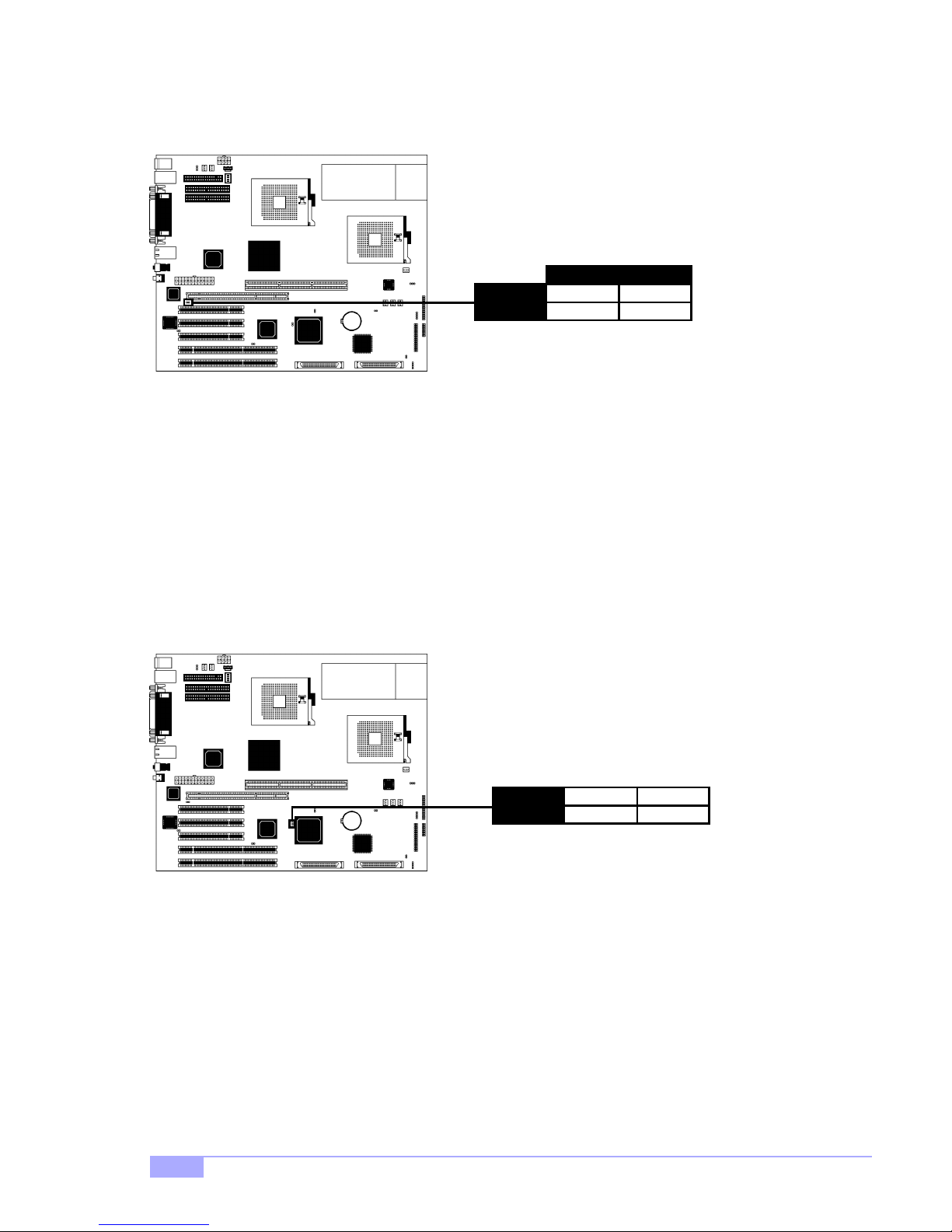
E. Onboard LAN Enable/Disable (J28)
This jumper can disable the onboard LAN port.
J28
LAN
close
disable
* default is OPEN
open
enable
F. Onboard SCSI Enable/Disable (J51)
This jumper can disab le the on boa rd SCSI por ts. P lease note that both SCSI por ts wi ll be di sab led at the
same ti me.
J51
close
disable
* default is OPEN
open
enable
14
http://www.tyan.com
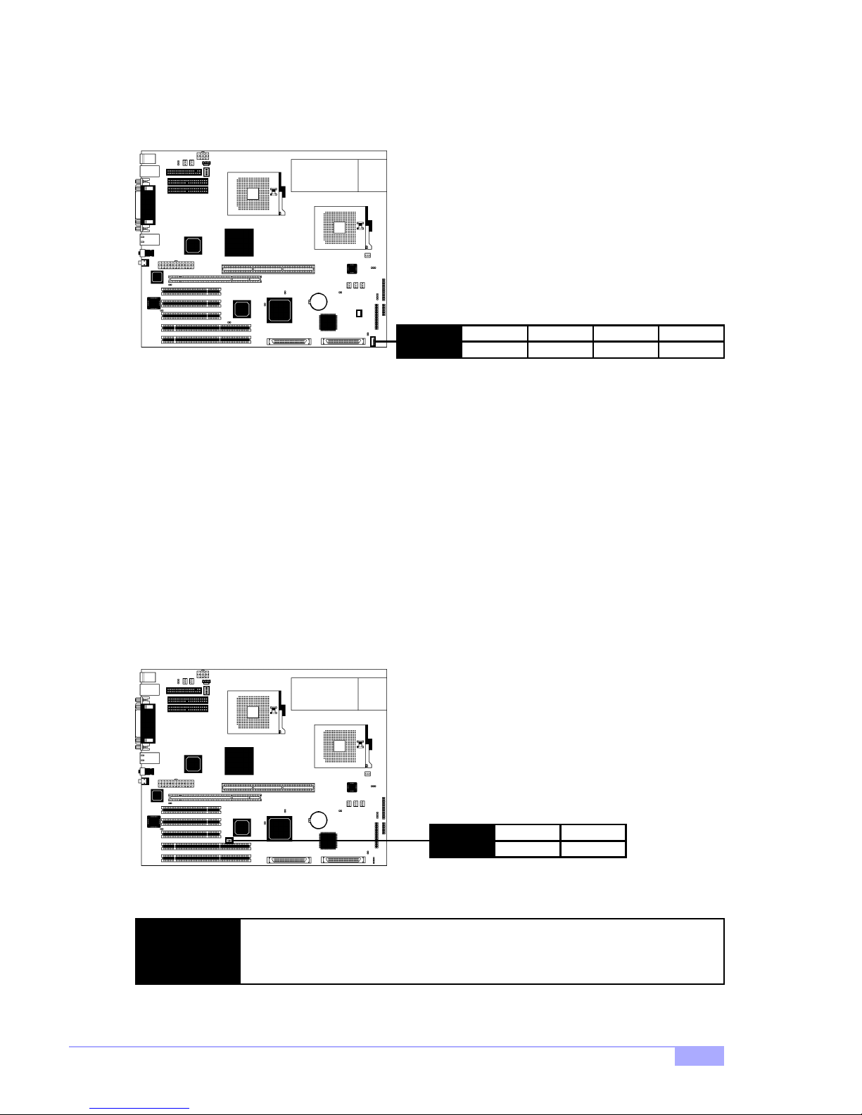
G. Speaker Connector (J23)
This is the 4-pin connector for a speaker.
J23
H. PCI Speed Select (J25)
This connector controls the speed of the 64-bit PCI slots.
1
power in2no connect3no connect4speaker
Tyan takes no responsibility and will not be held liable for damage related to the
NOTE:
alteration of J25 from the correct setting corresponding to your PCI card manufacturer’s designated operating speed.
Thunder i860 S2603
J25
open
66 MHz
* default is OPEN
close
33 MHz
15
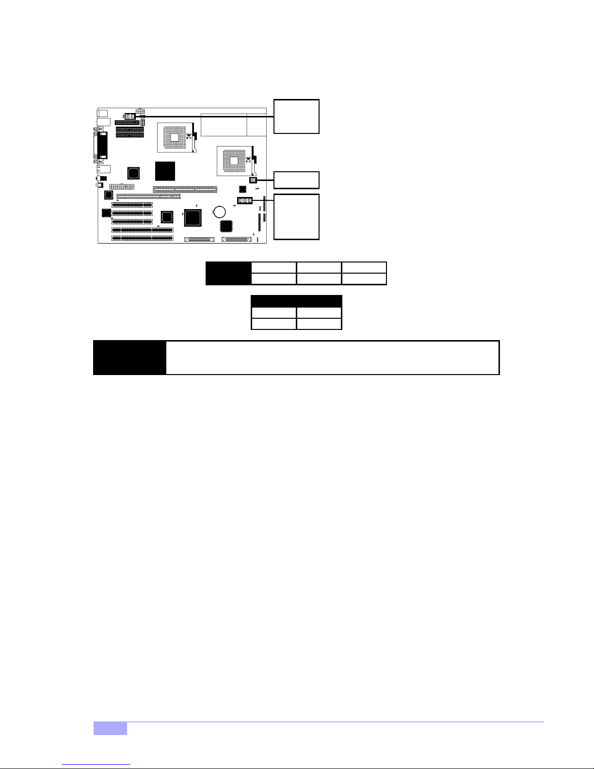
I. FAN Connectors (FAN)
These are the 3-pin connectors for both CPU and chassis fans.
J34
J33
J32
J36*
J35
J37
FAN
NOTE:
J. Soft Power Connector
The soft power connector is part of jumper block J24 (pins 6 and 8). This board uses the chipset for power
management, inclu ding turning on and off the system. If the power button function option in the BIOS
Power Managemen t menu i s set to “On/ Off” (which is t he defaul t), pressin g the power button on ce after
the BIOS has booted up will turn the syste m on and off. If the power button function is set to Suspend,
pressing the power button once will wa ke up the system or send it to Suspend mode. In this case, you
cannot turn the syste m off unless you sh ut down t hrough the Windows op erating system o r you hold the
power button down for four seconds (BIOS-dependent feature).
K. Hardware Reset Switch Connector Installation
The reset switch on your chassis case provides you with the Hardware Reset function, which is the same
as power on/off, except that the system will immediately execu te a cold start after the reset button is
pushed. The reset switch needs to be connected to jumper block J24 (pins 5 and 7).
NOTE: The FA N conn ec to rs a re 12V at 1.2A. Tyan takes no responsibility and will
not be held liable for damage related to the misuse of these jumpers.
1
ground
Specifications
Amperage 1.2A
2
+12V
12VVoltage
3
speed
L. Flash Utility
You can upgrade the BIOS of this motherboard by using the Flash Utility (see p.47). Check the Tyan website for more details: http://www.tyan.com
* indicates an optional feature available on some Thunder i860 models
16
http://www.tyan.com
2.7 Mounting the Motherboard into the Chassis
Your chassis m ay include m ounting hardw are. If mounti ng hardwa re was included, yo u can use the fo llowing examples to help you in installing your motherboard into the chassis.
The chassis may h ave com e with th e studs integrated into t he chassis wall, so in those ca ses you wou ld
only need to us e scre ws (possib ly inclu ded wi th you r chass is) to i nstall th e mot herboa rd. S ee the examples (Figure 2.0, shown below) for more details.
If the chassis includes mounting hardware without the studs pre-installed, then you will need to install the
motherboard usin g the mounting hardware as sho wn in the examples below. Remember not to overtighten any of th e screws, or you migh t risk breaki ng intern al traces i n the surroun ding ar ea, or dam age
the motherboard in some other way.
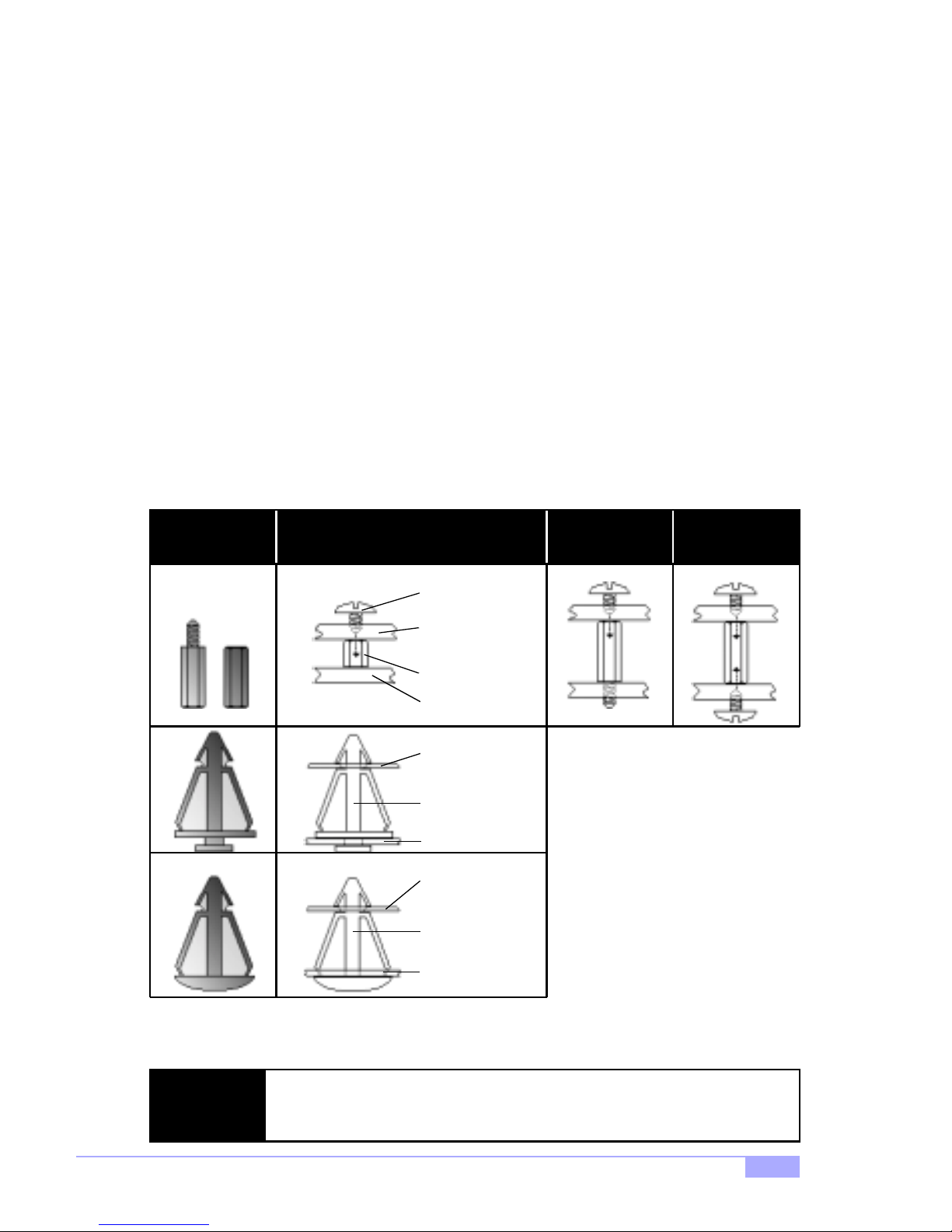
Other examples of how to install your motherboard using other hardware (that may or may not have been
included with your chassis) are shown below.
One solution for installing motherboardType of hardware Another solution Another solution
screw
motherboard
base
stud
chassis wall
motherboard
base
standoff
chassis wall
motherboard
base
standoff
chassis wall
Figure 2.0
The diagrams above are only representative of a few solutions for installing a
NOTE:
motherboard into the chassis. The installation procedure for installing your m otherboard may differ.
Thunder i860 S2603
17
2.8 Installing Memory
Please keep in mind that although some memory modules may appear to be high-quality, they may contain inferior or substandard parts. The type of memory you choose to install should be checked against
the memory compatibility list, which is available from Tyan’s website at http://www.tyan.com
Memory Installation Procedure
Step
Step
Step
Line up your module so that the pins fit into the slot. There is only one way your mem ory
1
module can fit proper ly. Make sure that the short row of pins is line d up with the short ga p in
the RDRAM socket. See Fi gu re 2.1 (on p.17) for graphic det ail s o n h ow t he memory should
be installed.
Insert the memory mo dule by pu shing it int o the socke t with even force. Do not insert one
2
end and then the other : install th e whole module at once or yo u might da mage t he memory
module and/or the socket.
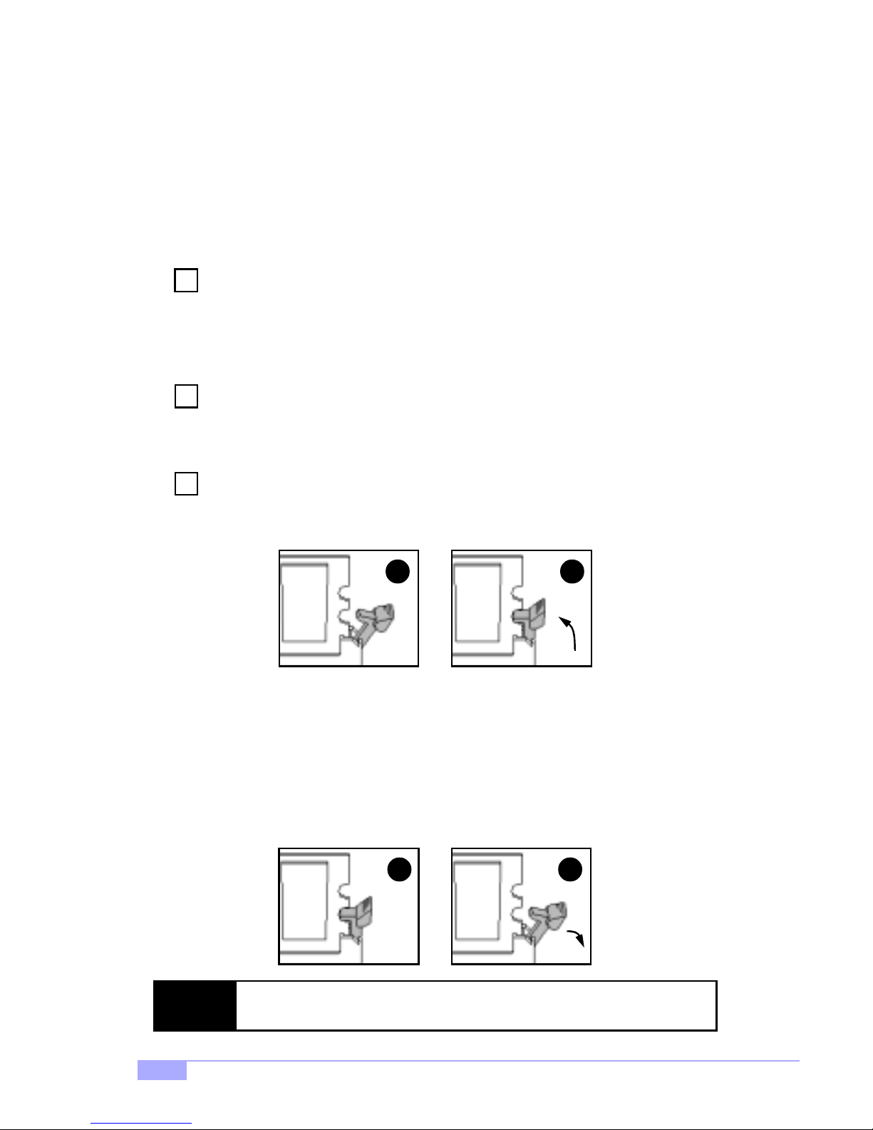
Lock the memory into pla ce by pushing the clips back on ei ther end of the socket onto the
3
notches in the ends of the memory module, as shown below.
1 2
Memory Uninstallation Procedure
Removing the RIMM is just the reverse: simply pull back the clips from the memory module (as shown
below), and carefully pull the module straight out. Place the memory modules in an anti-static bag as
soon as you remove them to avoid static damage.
NOTE:
Also take care that you do not cause yourself injury if you are removing the
memory modules after using the motherboard, since the module(s) may be hot.
18
21
http://www.tyan.com
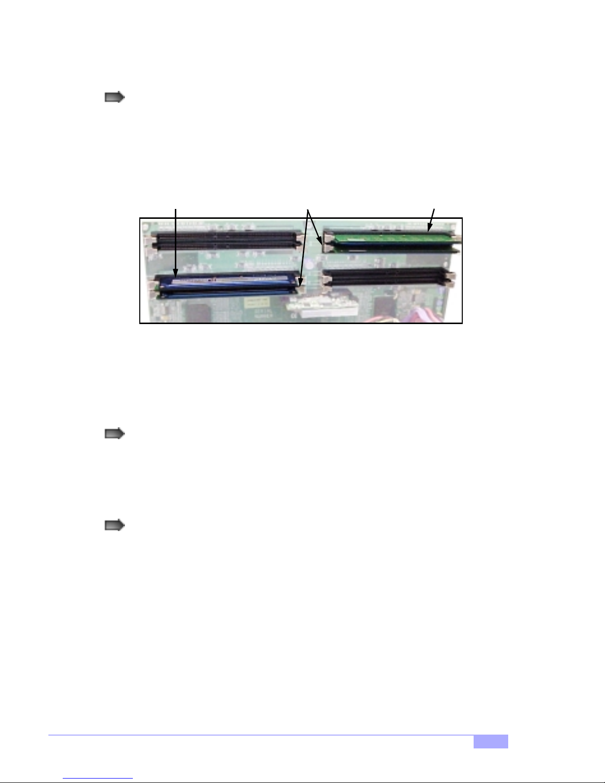
Here are some details of memory installation for this board:
Inner and outer RIMM sockets must be matching (e.g. if you have one RIMM module in the inner
socket, another RIMM module must be installed in the other inner socket, and so on).
See p. 20 and Figure 2.1 (below) for an example.
Inner Modules
Outer Module Outer Module
are matching
Figure 2.1
Any empty slots must be filled with C-RIMM Continuity modules. Tyan has included (2) C-RIMM
modules for your convenience (examples** are shown above in Figure 2.1).
This motherboard supports up to 2GB* PC800 ECC Registered RDRAM. Check the Tyan memory compatibility section of the website for more details: http://www.tyan.com
* not verified at time of print, check the Tyan website for updates: http://www.tyan.com
** note: the examples may not necessarily represent the actual C-RIMMs included with the board.
Thunder i860 S2603
19
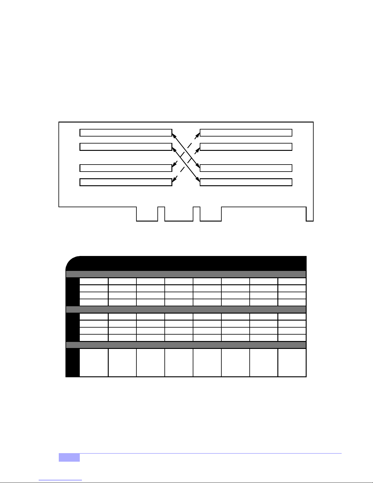
Memory Configuration Examples
Figure 2.2 and the table below should be used in conjunction to determine possible memory configura-
tions. Not all possible configurations are listed. (NOTE: C-RIMM means Continuity RIMM)
NOTE: The Rambus memory modules must be installed in a top-to-bottom fashion (e.g. fill in socket 1,
then socket 2, and match the memory quantity in socket 3 with socket 1’s memory quantity, and then
match the memory quantity in socket 4 with socket 2’s memory quantity, and so on).
A1
A2
D1
D2
64MBx1
C-RIMM
64MBx1
C-RIMM
A1
A2
B1
B2
C1
C2
D1
D2
Figure 2.2 - Overhead view of memory banks*
Total of 4GB** PC800 Registered RDRAM possible
64MBx1
C-RIMM
64MBx1
C-RIMM
64MBx1
64MBx1
64MBx1
64MBx1
128MBx1
C-RIMM
128MBx1
C-RIMM
128MBx1
128MBx1
128MBx1
128MBx1
256MBx1
C-RIMM
256MBx1
C-RIMM
512MBx1
C-RIMM
512MBx1
C-RIMM
512MBx1
512MBx1
512MBx1
512MBx1
C1
C2
B1
B2
* RIMM sockets are numbered in the diagram only, as an aid to proper memory installation
** not verified at time of print, check the Tyan website for updates: http://www.tyan.com
0
0
0
0
128MB
TOTAL
64MBx1
C-RIMM
64MBx1
C-RIMM
256MB
20
64MBx1
64MBx1
64MBx1
64MBx1
512MB 512MB 1024MB 1024MB 4096MB**2048MB**
128MBx1
C-RIMM
128MBx1
C-RIMM
128MBx1
128MBx1
128MBx1
128MBx1
256MBx1
C-RIMM
256MBx1
C-RIMM
512MBx1
C-RIMM
512MBx1
C-RIMM
http://www.tyan.com
512MBx1
512MBx1
512MBx1
512MBx1
 Loading...