

TYAN TIGER 200T, S2505T User Manual

TM
Tiger 200T
S2505T
User’s Manual
Revision 1.01
Copyright © Tyan Comput er Corp or ation , 2 001 . Al l rig hts reserved. No part of t hi s m an ual m ay be reproduced or translated without prior written consent from Tyan Computer Corp.
All registered and unregistered trademarks and company names contained in this manual are property of
their respective owners including, but not limited to the following.
Tiger 200T S2505T is a trademark of Tyan Computer Corporation.
Intel, Pentium III, Celeron are registered trademarks of Intel Corporation.
VIA, Apollo Pro133T are trademark s of VIA Technologies, Inc.
Promise, FastTrak100, FastBuild are registered trademarks of Promise Technology, Inc.
AwardBIOS is a trademark of Phoenix Software.
Windows is a trademark of Microsoft Corporation.
IBM, PC, AT, PS/2 are trademarks of IBM Corporation.
Information contained in this document is furnished by Tyan Computer Corporation and has been
reviewed for accuracy and reliability prior to printing. Tyan assumes no liability whatsoever, and disclaims
any express or implied warranty, relating to sale and/or use of Tyan products including liability or warranties relating to fitness for a particular purpose or m erchantability. Tyan retains the right to make changes
to product descriptions and/or specifications at any time, witho ut not ice. In no ev ent will Tyan be held liable for any direct or indirect, incidental or consequential damage, loss of use, loss of data or other malady
resulting from errors or inaccuracies of information contained in this document.

Table of Contents
Before you begin... .................................................................... Page 4
Chapter 1: Introduction
1.1
1.2
1.3
Congratulations! .........................................................................................................5
Hardware Specifications ............................................................................................6
Software Specifications ..............................................................................................7
.......................................................................
Chapter 2: Board Installation
2.1
2.2
2.3
2.4
2.5
2.6
2.6-A
2.6-B
2.6-C
2.6-D
2.6-E
2.6-F
2.6-G
2.6-H
2.6-I
2.6-J
2.6-K
2.6-L
2.6-M
2.7
2.8
2.9
2.10
2.11
2.12
2.13
2.14
2.15
Installation ..................................................................................................................8
How to install our products right... the first time ..........................................................8
Here are some safety tips ..........................................................................................8
Quick Reference for Jumpers ....................................................................................9
Map of Motherboard Jumpers ..................................................................................10
Setting up Jumpers and Onboard Connectors .........................................................11
Front Panel Connector ........... ............................... ..... ................................ ..... .........11
CMOS Reset ............................................................................................................11
IDE RAID Enable/Disable ........................................................................................12
Onboard VGA Enable/Disable .................................... ...... ............................... ........12
FAN Connectors ............................... ..... ...... ............................... ..... ........................13
CPU Frequency Ratio Jumpers ...............................................................................13
Serial Port Connector ...............................................................................................14
USB Connector ........................................................................................................14
Wake-on-Ring, Wake-on-LAN .................................................................................15
IDE RAID Connectors ..............................................................................................15
Soft Power Connector Installation ............................................................................16
Hardware Reset Switch Connector Installation ........................................................16
Flash Utility ....................... ...... ..... ............................... ...... ............................... ..... ...17
Mounting the Motherboard in the Chassis ................................................................18
Installing Memory .....................................................................................................19
Removing a DIMM ...................................................................................................20
Buffered vs. Unbuffered Memory ............................................................................20
Suggested Memory Configurations ..........................................................................21
Installing the CPU and Cooling Fan ............................................ ..... ........................22
Installing the CPU ....................................................................................................22
Installing the Cooling Fan(s) ....................................................................................23
Connecting IDE and Floppy Drives ..........................................................................24
Connecting Floppy Drives ........................................................................................25
Installing Add-on Cards ............................................................................................26
Connecting PS/2, USB, and Serial Devices .............................................................27
Connecting the Power Supply ..................................................................................28
You are done! ...........................................................................................................29
Frequently Asked Questions (FAQ) .........................................................................30
.............................................................
5
8
Chapter 3: BIOS Setup
Introduction to the BIOS Setup .................................................................................31
Starting Setup .............. ..... ...... ............................... ................................ ..... .............31
Setup Keys ...............................................................................................................32
Getting Help .............................................................................................................32
In Case of Problems .................................................................................................32
Setup Variations ................................ ..... ...... ..... ..... ..... ...... ............................... ..... ...32
2
....................................................................
http://www.tyan.com
31

Main Setup ................... ..... ...... ..... ............................... ................................ ..... ........333.1
Standard CMOS Setup ............................................................................................333.2
3.2-A
3.2-B
3.2-C
3.2-D
3.3 Advanced BIOS Features ........................................................................................35
3.4
3.5
3.6
3.7
3.8
3.9
3.10
3.11
Date/Time ................................................................................................................33
IDE Primary/Secondary Master/Slave ......................................................................33
Table of IDE device settings .....................................................................................34
Memory ....................................................................................................................35
Advanced Chipset Features .....................................................................................37
Integrated Peripherals ..............................................................................................38
Power Management Setup .......................................................................................39
PnP/PCI Configuration .............................................................................................41
PC Health Status ......................................................................................................41
Frequency/Voltage Control ......................................................................................42
Set Supervisor Password / Set User Password .......................................................42
Exit BIOS Setup .......................................................................................................42
Chapter 4: System Resources
4.1
4.2
Beep Codes .............................................................................................................43
Flash Utility ....................... ...... ..... ............................... ...... ............................... ..... ...43
.......................................................
Appendix I: RAID Installation* 44.......................................................
Promise FastTrak100 RAID Configuration Utility .....................................................44
Appendix II: Glossary
Technical Support ....................................................................................................56
Returning Merchandise for Service ..........................................................................56
43
50.......................................................................
* optional feature available on some Tiger 200T models
Tiger 200T S2505T
3

Before you begin...
Check the box contents!
The retail motherboard package should contain the following:
Tiger 200T S2505T motherboard
34-pin floppy cable
(2) UltraDMA-100/66/33 IDE cables
(optional on some Tiger 200T models)
I/O shield*
(optional on some Tiger 200T models)
Tiger 200T user’s manual
Ty an driver CD
If any of these items are missing, please contact your vendor/dealer for replacements before continuing
with the installation process.
* If you require a different I/O shield solution, please contact your chassis vendor
4
http://www.tyan.com

Chapter 1: Introduction
1.1 Congratulations!
You now own one of the premier dual processing solutions on the market!
The Tiger 200T is a high performance motherboard designed for server and performance applications
®
that require the power of dual Intel
FC-PGA processor. This motherboard utilizes the VIA Apollo Pro133T chipset and can support CPU
speeds of 500 MHz through 1.13+ GHz and front side bus speeds of 100 MHz or 133 MHz. Please see
Tyan’s website for updates and information concerning CPU information and support:
This integrated p erfo rm an ce boa rd is su ppo rte d in an ATX form factor. Some of the features incl ude d are
onboard UltraDMA -1 00 /66/ 33 sup por t, and ( optional) Promise
With I/O and drive control ler su pport onboar d, the five 3 2-bi t PCI v2.2 sl ots and o ne IS A slot are f ree for
numerous types of add-o n expansion cards. The four 168-pin DIMM socke ts can support up to 2GB* of
buffered or unbuffered PC100 SDRAM, or up to 1.5GB of buffered or unbuffered PC133 SDRAM.
Pentium™ III FC-PGA processors (universal) or a single Celeron™
http://www.tyan.com
®
IDE RAID.
Remember to visit Tyan’s website at http://www.tyan.com. There you can find information on all of
Tyan’s products with FAQs, distributors list, and BIOS settings explanations.
* check the Tyan website for updated details on memory compatibility: http://www.tyan.com
Tiger 200T S2505T
5

1.2 Hardware Specifications
Processor Information
Expansion Slots
Chipset Information
Hardware Monitoring
Memory
Integrated PCI IDE
Dual Universal PGA370 ZIF Sockets
Intel Pentium III (FC-PGA) 500MHz - 1.13GHz+
Celeron (single socket configuration only) FC-PGA
Onboard VRM 8.5 spec
Front side bus support for 100 or 133MHz
Five 32-bit PCI v2.2 compliant slots
One ISA slot
Total s ix usable slots
VIA Apollo Pro133T chipset
(VT82C694T and VT82C686B)
Integrated hardware monitoring
3-pin Fan Monitoring headers
Temperature and Voltage Monitoring
3-pin Wake-on-Ring header
3-pin Wake-on-LAN header
Four 168-pin 3.3V DIMM sockets
Supports 1.5GB of 66/100/133MHz types of memory.
Supports both buffered/un buffer ed P C1 00 /133 SDR AM
Dual-channel master mode
Supports up to four Enhanced IDE devices
Support for UltraDMA-100/66/33 IDE devices and
ATAPI compliant devices
Integrated I/O
Integrated IDE RAID
(manufacturing option)
Integrated 2D/3D graphics
* Extra accessories can be purchased at the Tyan Online Store: http://www.etyan.com
*** 8MB may be available on some Tiger 200T models. Check the Tyan website for updates:
http://www.tyan.com
^ If your chassis supports frontside USB cables, it will usually come with those cables.
Check with your chassis vendor for details. Tyan does not provide frontside USB cables.
One floppy connector for up to two drives
Two 9-pin UART serial ports
One 25-pin ECP/EPP parallel port
Four USB ports (two ports via cable - optional*^)
PS/2 mouse and keyboard ports
Promise FastTrak100 IDE RAID controller
0/1/0+ 1 RAID options
Dual-channel master mode
Support for UltraDMA-100/66/33 IDE devices
ATI Rage XL PCI Accelerator
4 MB (or 8MB***) 1Mx16 SDRAM frame buffer
Standard 15-pin analog VGA port
6
http://www.tyan.com

BIOS
Award BIOS 2 (or 4****) Mbit Flash
Auto-detection of memory size
Auto-configuration of IDE hard disk types
User settings of hardware monitoring
Multiple boot options
DMI 2.0 compliant
Form Factor
Regulatory
1.3 Software Specifications
OS
ATX 2.03 (12” x 9.6”, 304.8mm x 243.84 mm)
One 20-pin ATX power connector
Stacked mouse & keyboard ports
Stacked two USB ports
Two serial ports, one parallel port
FCC (Declaration of Conformity)
European Community CE (Declaration of Conformity)
Operates with Windows 98/SE/ME,
Windows NT^^/2000
**** 4 Mbit BIOS may be available on some Tiger 200T models. Check the Tyan website for updates:
http://www.tyan.com
^^ Memory support dependent on operating system used. Check the Tyan website for updated details
on memory support for the Tiger 200T: http://www.tyan.com
Tiger 200T S2505T
7

Chapter 2: Board Installation
2.1 Installation
Once you’ve checked that everythin g is inside the box (se e p. 4 for detail s), you are then ready to inst all
your motherboa rd. T he mo untin g hole pattern of th e motherboard match es t he ATX board specifi ca ti on s,
so your chassis must be cap able of supporting an ATX board (check the mothe rboard dimensions p rovided on p. 7).
2.2 How to install our products right.. the first time.
Question: what’s the first thing I should do?
The first thing you should do is read the user’s manual. It contains important information which will make
configuration and setup much easier, as well as provide information on device installation and component
setup. By reading through the manual completely before installing your motherboard, you will have a
complete overview on the installation.
2.3 Here are some safety tips:
(1) Ground yourself properly before removing your motherboard from the antistatic bag. Unplug
the power from your computer power supply and touch any metal part on the computer case. (You
might also want to wear a grounded wrist strap.)
(2) Hold the motherboard by its edges and do not touch the bottom of the board.
(3) Avoid touching motherboard components, IC chips, connectors, and leads.
(4) Avoid touching pins of memory modules and chips.
(5) Place motherboard on a grounded surface or on the antistatic bag.
Having reviewed the precautions above, the next step is to take the motherboard out of the cardboard box
and static bag, hold it by its edges, and place it on a grounded antistatic surface (such as the bag it came
in), component side up. Then, inspect the board for damage.
NOTE: DO NOT APPLY POWER TO THE BOARD IF IT HAS BEEN DAMAGED!
Press down on any of the socketed ICs if it appears that they are not properly seated (the board should
still be on an antistatic mat or on top of the bag it came in). Do not touch the bottom of the board. Remember, don’t take any electronic device out of its protective bag until you are ready to actually start installing
it into the computer case (e.g. setting jumpers, etc.) If you do not ground yourself, you risk zapping the
motherboard or adapter card. Subsequent problems may not arise immediately because electrostatic discharge, unlike physical damage, causes the device to fail over time.
8
http://www.tyan.com
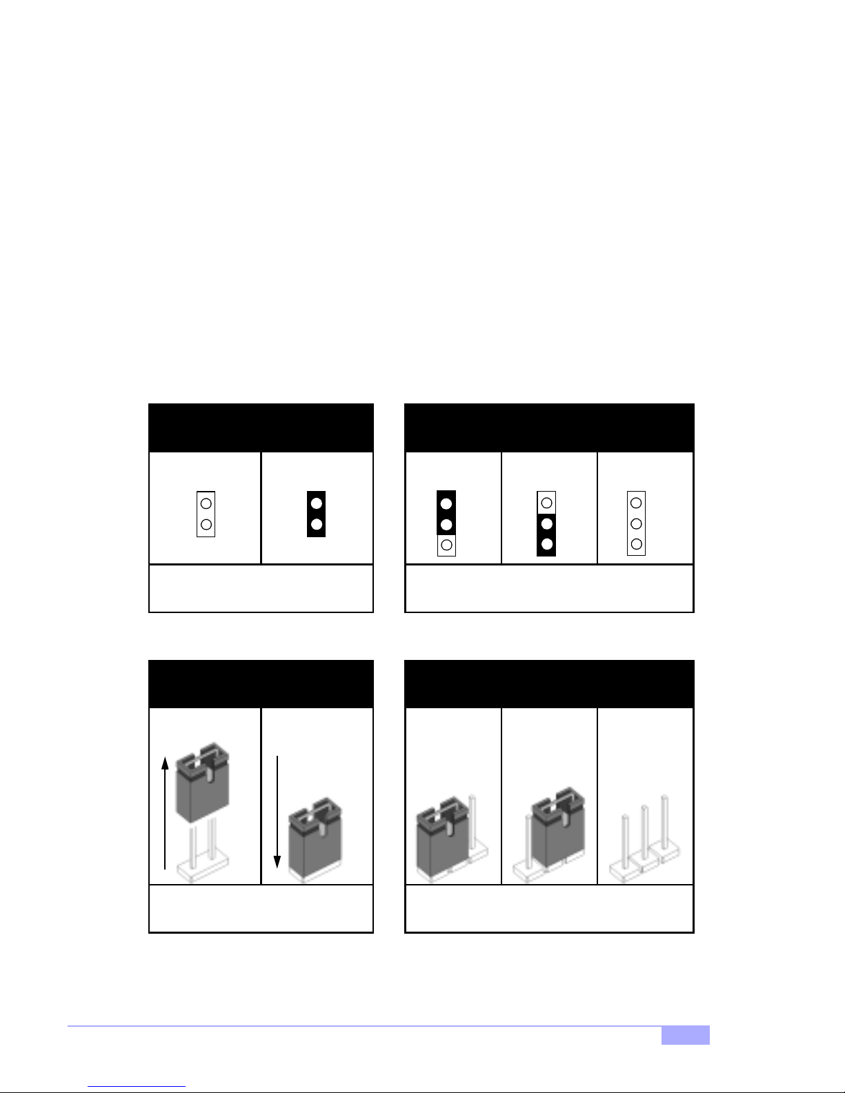
2.4 Quick References for Jumpers
In this manual, the term “closed” and “on” are used when referring to jump ers (or jumper pins) th at are
active; “open” a nd “off” a re u sed whe n re fer ri ng to ju mp ers (or jumper pin s) th at a re inactive. See Figure
2.0a and Figure 2.0c for examples of “on” and “off” pins and jumpers.
Jumpers and pins are con nected by slipping the plasti c jumper connector over the top of two adjacent
jumper pins ( indicated by 1- 2 or 2-3). The met al rod inside t he plastic sh ell b ridges the ga p betw een the
two pins, completin g the circuit. See Figure 2 .0b and Figure 2.0d for more examples of 3-pin jumper
connections. NOTE: The small number “1” indicates pin 1.
The tables and maps on the following pages will help you set the jumpers for CPU speed, infrared, and
external connector pin assignments, among others. The miniature motherboard maps will help you locate
the jumpers on your board. Full page maps of the motherboard can be found on the next two pages.
2-pin jumpers
off on
Figure 2.0a
(overhead view)
1-2 2-3 open
3-pin jumpers
1
2
3
Figure 2.0b
(overhead view)
1
2
3
2-pin jumpers 3-pin jumpers
1-2 2-3 openoff on
1
2
3
Figure 2.0c
(front angle view)
Tiger 200T S2505T
11
Figure 2.0d
(front angle view)
9
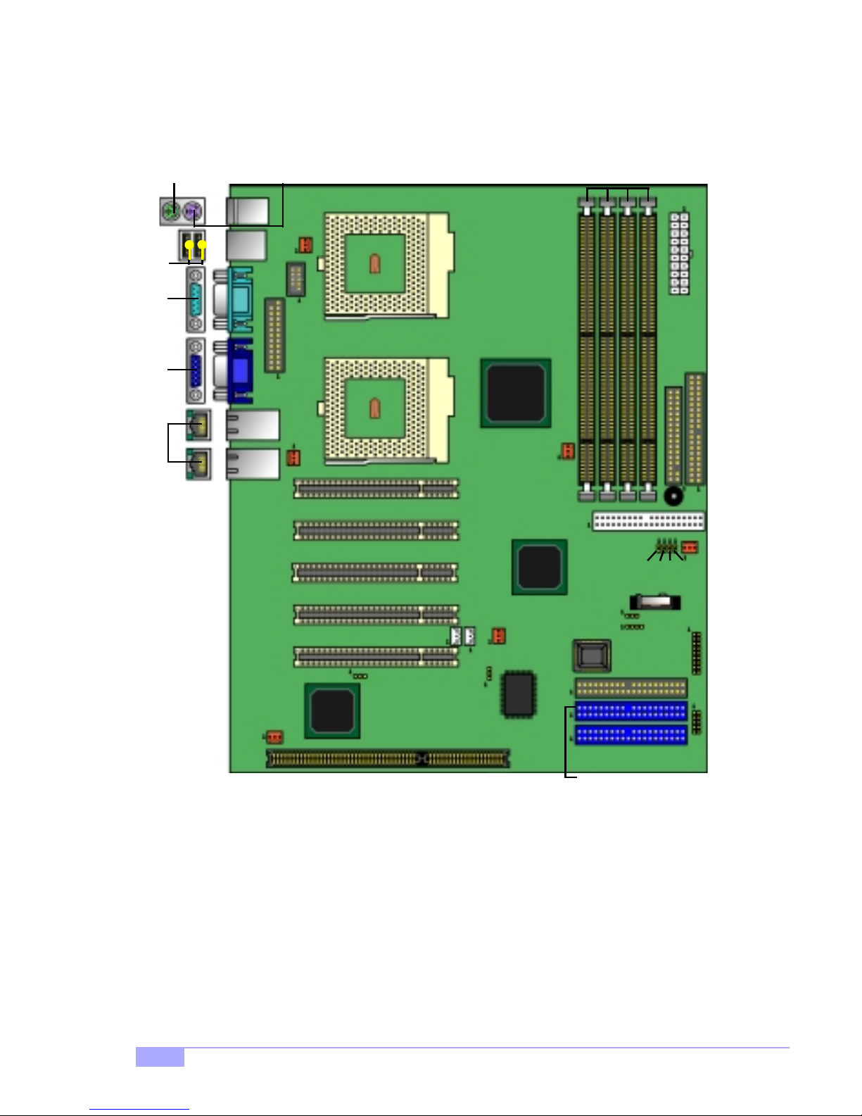
2.5 Map of Motherboard Jumpers
Mouse port
(upper port)
USB
Ports
Serial
port A
port
Video
LAN
ports
Keyboard port
(lower port)
FAN1
Serial
Port B
PJ2
FAN3
PCI1
PCI2
CPU1
CPU2
VIA
VT82C694T
chipset
Secondary IDE
Four SDRAM
Sockets
ATX Power Connector
FDD Connector
Primary IDE
FAN2
Buzzer
PCI3
PCI4
PCI5
FAN6
ATI
RAGE XL
JP10
ISA slot
J8
J9
JP11
FAN5
Promise
IDE RAID
JP4
JP5
JP6
JP7
JP8
J7
BIOS
J11
Secondary RAID IDE*
Primary RAID IDE*
FAN3
J12
USB2
* optional feature available on some Tiger 200T models
10
http://www.tyan.com

2.6 Setting up Jumpers and Onboard Connectors
Pinouts for certain connectors are available on the Tyan website: http://www.tyan.com
2.6-A. Front Panel Connecto r (J12)
12
Pwr LED+
Slp LED+
34
5
6
switch
ground
10
9
no connect
12
11
13
1516
1718 DRIVER
14
no connect
no connect
VCC
LED
HDD
Sw
Rst
IR
VCC+
ground
ground
switch 7 8
no connect
RX
GND
TX
no connect
Pwr
LED
Sw
Pwr
SPEAKER
Your chassis will usually come with connectors to install onto
the motherboard, such as HDD and Power LEDs. The Front
Panel Connector (J12) has been implemented for such purposes.
2.6-B. CMOS Reset (JP8)
Abbreviations
ResetRst
Pwr Power
JP8
1-2
normal
* default is 1-2
2-3
clear
If you have been locked out of your system beca use you forgot your password, or set the CMOS incorrectly, or have just finished flashing your BIOS follow the instructions below.
1. Power off the system
2. Close pins 2-3 on JP8
3. Wait about three seconds
4. Close pins 1-2 on JP8, then power on the system again
By following this procedure, you will erase your password and reset the CMOS.
Tiger 200T S2505T
11
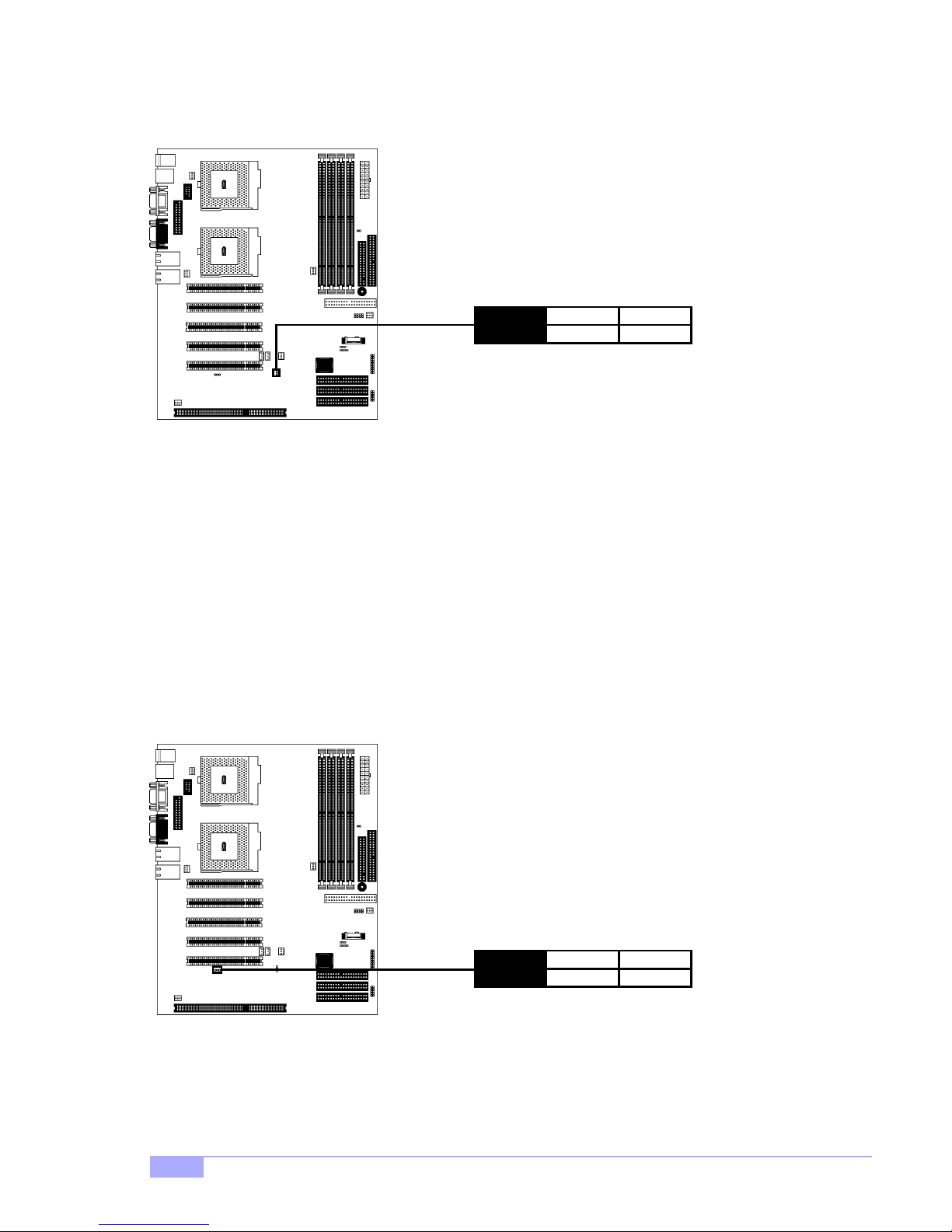
2.6-C. IDE RAID Enable/Disable (JP11)*
Jumper JP11 will allow you to enable or disable the (optional) onboard IDE RAID feature.
JP11
2.6-D. Onboard VGA Enable/Disable (JP10)
Jumper JP10 will allow you to enable or disable the (optional) onboard video features.
1-2
enable
* default is 1-2
2-3
disable
* optional feature available on some Tiger 200T models
12
JP10
1-2
enable
* default is 1-2
http://www.tyan.com
2-3
disable
2.6-E. FAN Connectors (FAN1, FAN2, FAN3, FAN4, FAN5, FAN6)
These FAN connectors can be used to install cooling devices. FAN1 and FAN3 are for CPU1 and CPU2,
respectively.
FAN1
CPU1
FAN2
CPU2
FAN3
FAN4
FAN5
FAN6
Specifications
FAN
1
ground
2
+12V
3
speed
Amperage 1.2A
12VVoltage
NOTE:
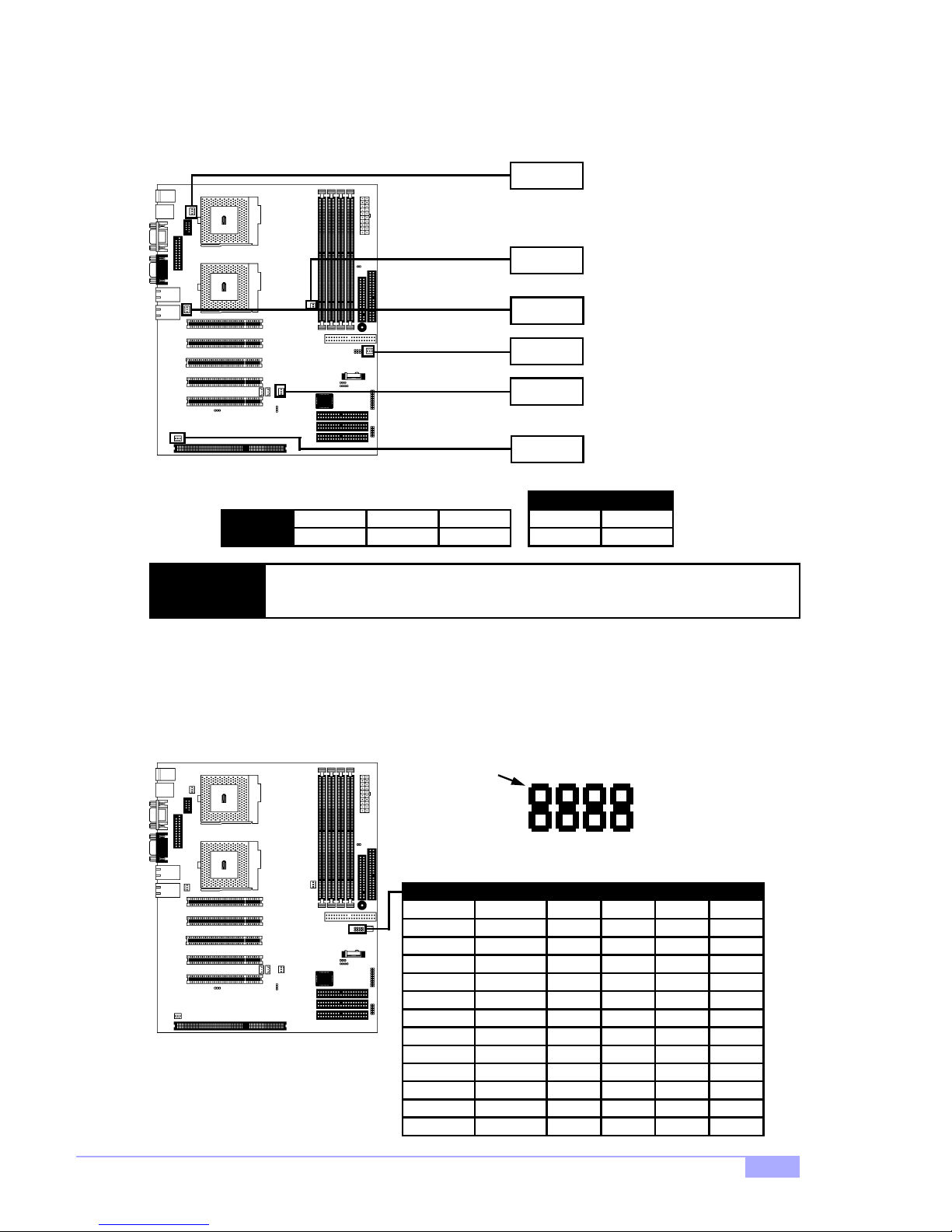
2.6-F. CPU Frequency Ratio Jumpers (JP4, JP5, JP6, JP7)
For non-retail/engineering sample CPUs, the frequency ratio can be adjusted. NOTE: Tyan takes no
responsibility and will not be held liable for damage from incorrect setting of these jumpers from
the CPU manufacturer’s specifications.
The FAN connectors are 12V at 1.2A. Tyan takes no responsibility and will not be
held liable for damage related to the misuse of these fan headers.
1.0BGHz
1.33GHz
733MHz
866MHz
1.06GHz
1.2GHz
933MHz
800EBMHz
1.13GHz
1.266GHz
20EMHz
20EMHz
PIN1
JP4, JP5, JP6, JP7
RATIO
133x7.5
133x10.0
133x5.5
133x6.5
133x8.0
133x9.0
133x7.0
133x6.0
133x8.5
133x9.5
10x2.0
10x2.0
JP5
JP6
JP4
JP4 JP5 JP6 JP7Freq.
ON OFF
OFF
OFF OFF
ON ON
OFF
ON ON
ON ON
ON ON ON
ON ON
ON
ON ONON ON
OFF OFF OFF OFF
JP7
OFF OFF
ON
OFF OFF
OFF OFF
OFF
ON
OFF OFF
OFF
OFF OFF
ONON
OFF
ON
OFF
OFF
OFF
OFF
Tiger 200T S2505T
13
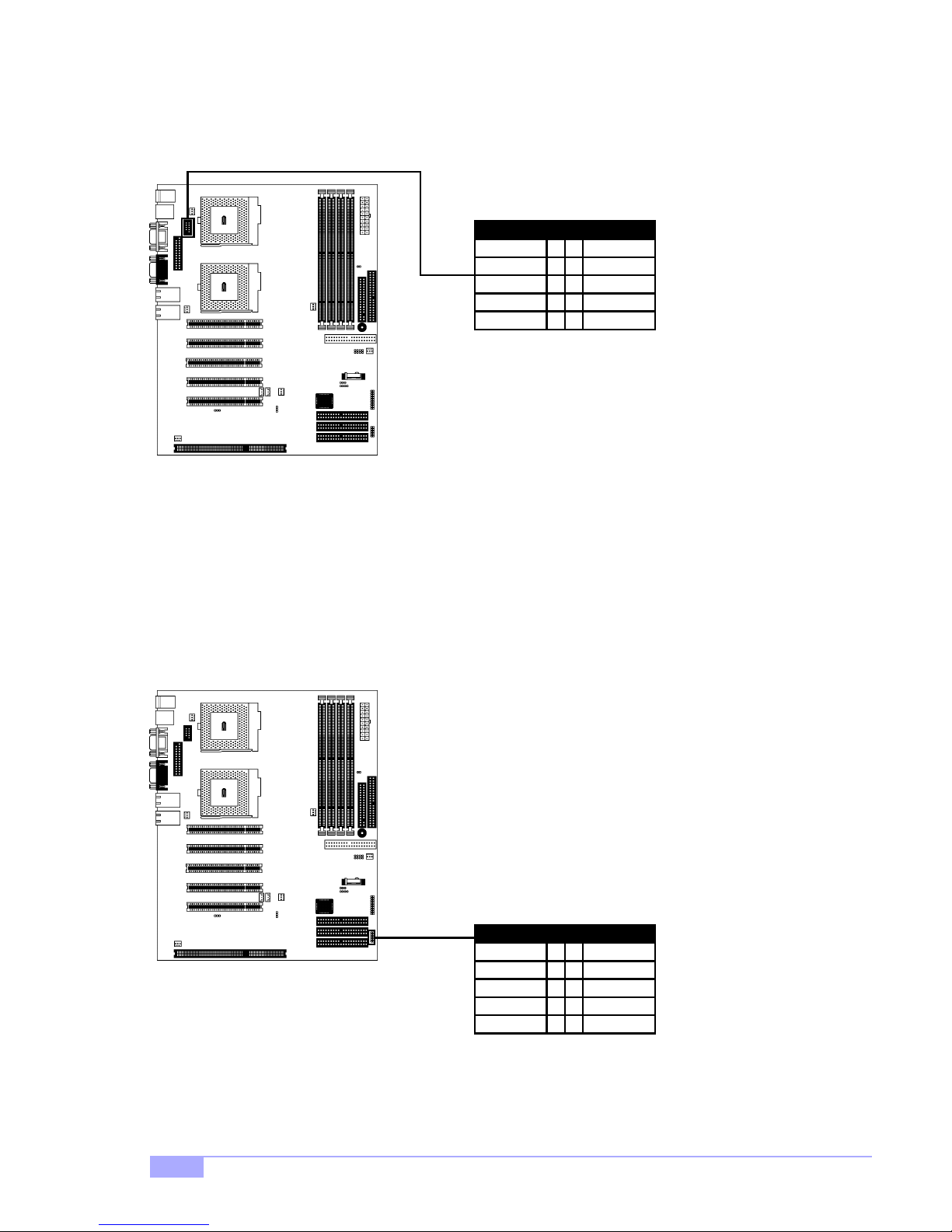
2.6-G. Serial P ort Connector (“COM1” or Serial Port B)*
This header can be used to connect an (optional) serial port. More details available on the Tyan website:
http://www.tyan.com
Serial Port B Header
RXDCD 1 2
34
56
78
910
DTRTX
DSRGND
CTSRTS
NC/KEYRI
2.6-H. USB Connector (USB2)**
This header can be used to connect the (optional) USB cable. Pinouts for USB2 are shown below.
USB Connector (USB2)
VCCVCC 1 2
34
56
78
910
DT4 -DT3 -
DT4 +DT3 +
GNDGND
GNDGND
* extra accessories can be purchased at the Tyan Online Store: http://www.etyan.com
** if your chassis supports frontside USB cables, it will usually come with those cables. Check with your
chassis vendor for details. Tyan does not provide frontside USB cables.
14
http://www.tyan.com
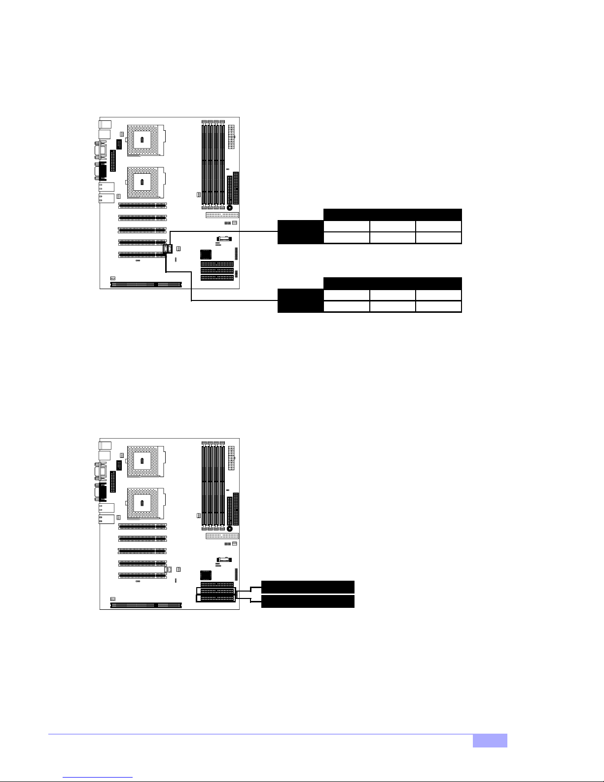
2.6-I. Wake-on-Ring, Wake-on-LAN (J8, J9)*
These headers can be used to connect the (optional) WOR and WOL devices. WOR is J8, and WOL is
J9.
Wake-on-LAN (WOL)
J9
J8
1
1.5VSB
Wake-on-Ring (WOR)
1
1.5VSB
2
GND
2
GND
3
WOL
3
WOR
2.6-J. IDE RAID Connectors (IDE3, IDE4)*
These headers can be used to connect the (optional) IDE RAID devices. IDE3 is the Primary IDE RAIDconnector, and IDE4 is the Secondary IDE RAID connector.
IDE3
IDE4
* optional feature available on some Tiger 200T models
Tiger 200T S2505T
15
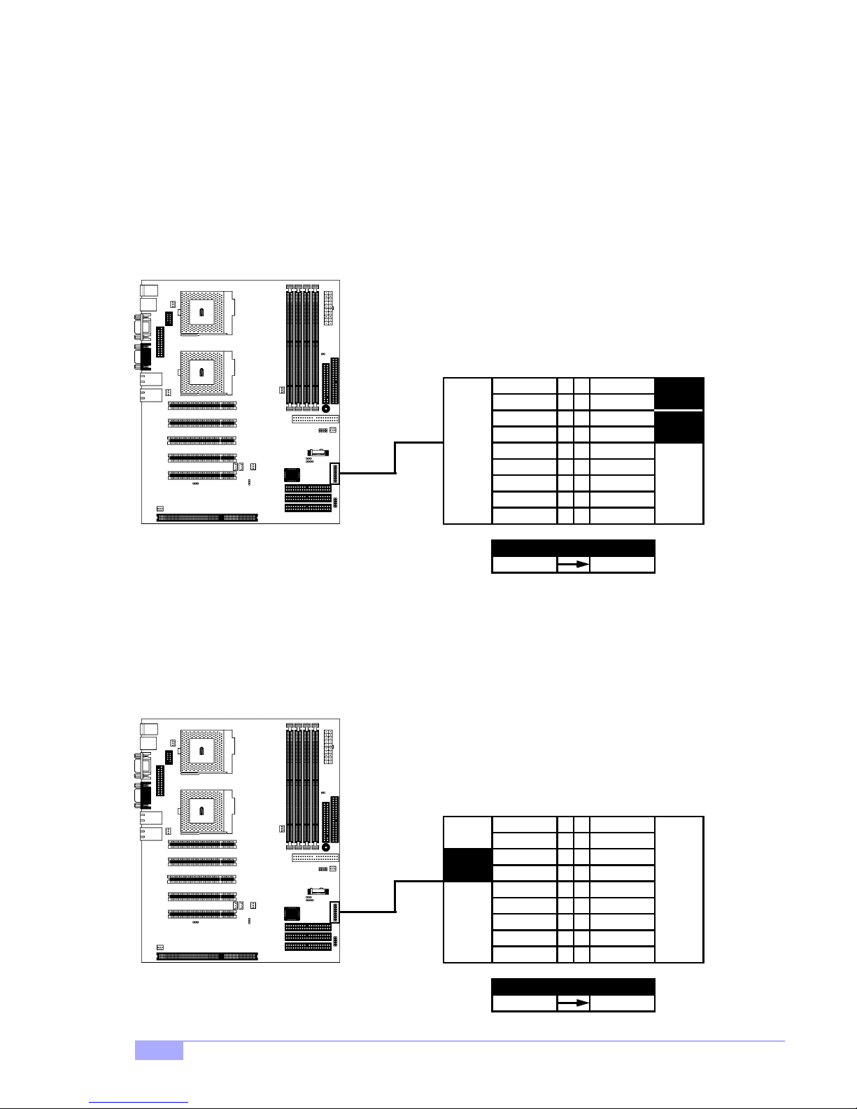
2.6-K. Soft Power Connector Installation
The soft power con nect or i s p ar t of t he F ro nt Pa nel ju mpe r b lock J12 (pins 6 and 8). T his bo ard use s the
chipset for power management, including turning on and off the system. If the pow er button function
option in the BIO S Pow er M ana ge men t me nu is se t to “ On/O ff”, pre ssi ng the p ower button once after the
BIOS has booted up will turn the system on and off. If the power button function is set to Suspend, pressing the power button once will wake up the syste m or send it to Susp end mo de. In this case , you canno t
turn the system off unless you sh ut down through the Windows ope rating system or you hold t he power
button down for four seconds (BIOS-dependent feature).
12
Pwr LED+
34
5
78
9
10
12
11
14
13
1516
1718
Slp LED+
6
ground
switch
Pwr
LED
Sw
Pwr
Abbreviations
Pwr Power
2.6-L. Hardware Reset Switch Connector Installation
The reset switch on your chassis case provides you with the Hardware Reset function, which is the same
as power on/off, except that the system will immediately execu te a cold start after the reset button is
pushed. The reset connector is part of the Front Panel jumper block J12 (pins 5 and 7).
12
34
Sw
Rst
ground
switch 7 8
5
10
9
12
11
14
13
1516
1718
6
16
Abbreviations
ResetRst
http://www.tyan.com
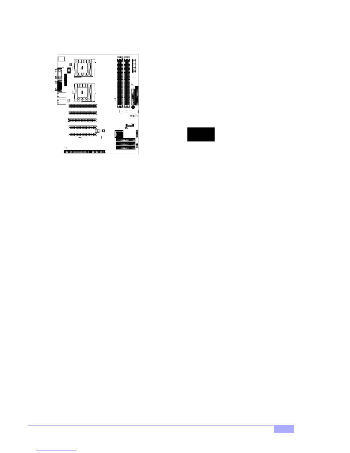
2.6-M. Flash Utility
You can upgrade the BIOS of this motherboard by using the Flash Utility. Check p. 43 for details.
BIOS
Tiger 200T S2505T
17
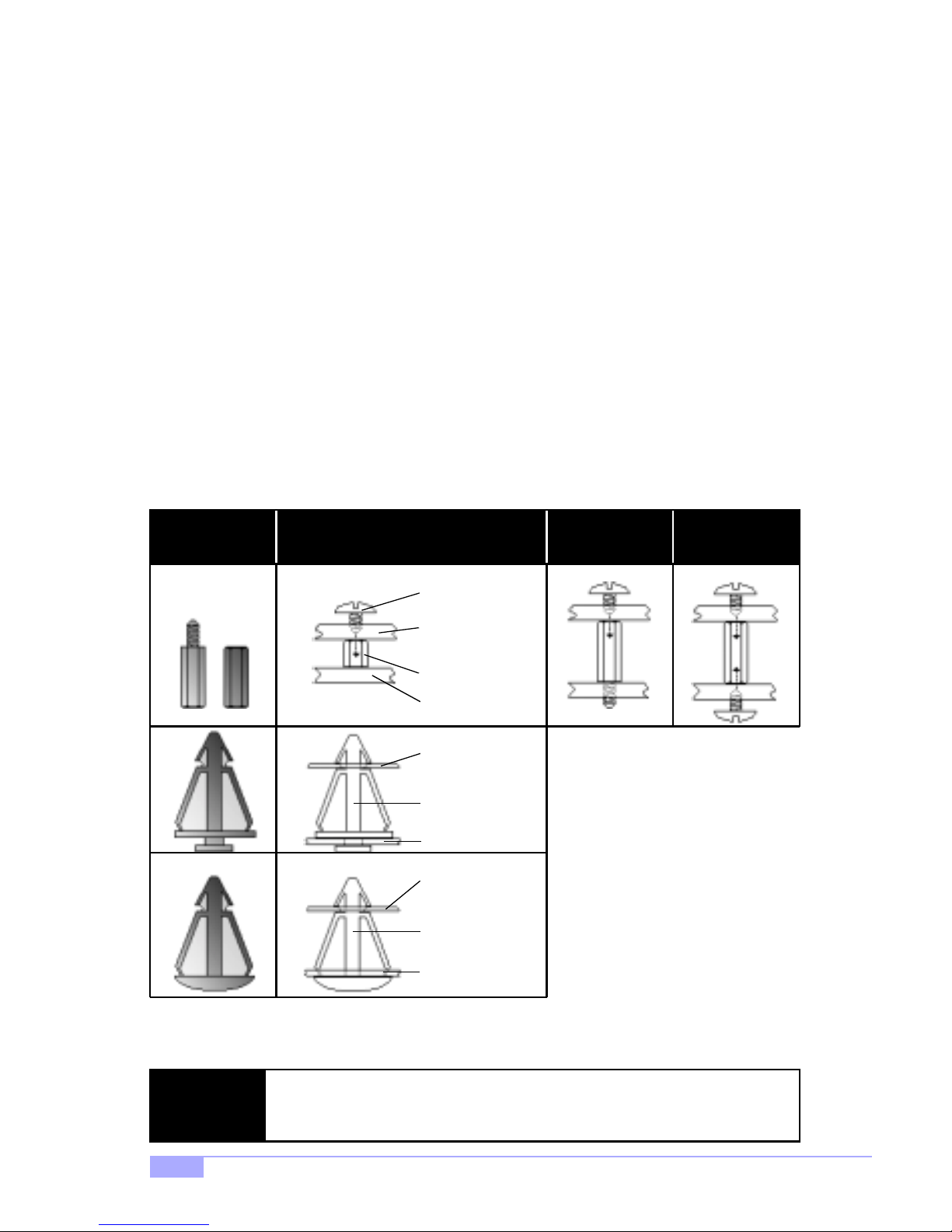
2.7 Mounting the Motherboard into the Chassis
Yo ur chassis may includ e mounting hardware. If m ounting har dware was included, you can use the following examples to help you in installing your motherboard into the chassis.
The chassis may h ave com e with th e studs integrated into t he chassis wall, so in those ca ses you wou ld
only need to us e scre ws (possib ly inclu ded wi th you r chass is) to i nstall th e mot herboa rd. S ee the examples (Figure 2.0, shown below) for more details.
If the chassis includes mounting hardware without the studs pre-installed, then you will need to install the
motherboard usin g the mounting hardware as sho wn in the examples below. Remember not to overtighten any of th e screws, or you migh t risk breaki ng intern al traces i n the surroun ding ar ea, or dam age
the motherboard in some other way.
Other examples of how to install your motherboard using other hardware (that may or may not have been
included with your chassis) are shown below.
One solution for installing motherboardType of hardware Another solution Another solution
screw
motherboard
base
stud
chassis wall
motherboard
base
standoff
chassis wall
motherboard
base
standoff
chassis wall
Figure 2.0
The diagrams above are only representative of a few solutions for installing a
NOTE:
motherboard into the chassis. The installation procedure for installing your m otherboard into the chassis may differ.
18
http://www.tyan.com
 Loading...