

TYAN S2505 User Manual

TM
Tiger 200
S2505
Motherboard User’s Manual
Revision 1.01
Copyright © Tyan Computer Corporation, 2000. All rights reserved. No part of this
manual may be reproduced or translated without prior written consent from Tyan
Computer Corp.
All registered and unregistered trademarks and company names contained in this
manual are property of their respective owners including, but not limited to the following.
Tiger 200 S2505 is a trademark of Tyan Computer Corporation.
AwardBIOS is a trademark of Phoenix Software.
Windows is a trademark of Microsoft Corporation.
IBM, PC, AT, PS/2 are trademarks of IBM Corporation.
Intel, Pentium III are registered trademarks of Intel Corporation.
VIA, Apollo Pro 133A are trademarks of Via Technologies, Inc.
Promise, FastTrak100 are a registered trademarks of Promise Technology, Inc.
ATI, Rage XL are trademarks of ATI Corporation.
Information contained in this document is furnished by Tyan Computer Corporation and has been reviewed for accuracy and reliability prior to printing. Tyan
assumes no liability whatsoever, and disclaims any express or implied warranty,
relating to sale and/or use of Tyan products including liability or warranties relating
to fitness for a partic ular pu rpose o r merch antabi lity. Tyan reta ins th e right to mak e
changes to product descriptions and/or specifications at any time, without notice.
In no event will Tyan be held liable for any direct or indirect, incidental or consequential damage, loss of use, loss of data or other malady resulting from errors or
inaccuracies of information contained in this document.

Table of Contents
Chapter 1: Introduction
1.1
1.2
1.3
1.4
1.5
Overview ....................................................................................................................4
Hardware Specifications ............................................................................................5
Software Specifications ..............................................................................................6
Technical Support ......................................................................................................7
Returning Merchandise for Service ............................................................................7
.............................................................
Chapter 2: Board Installation
2.1
2.2
2.3
2.4
2.5
2.6
2.6-A
2.6-B
2.6-C
2.6-D
2.6-E
2.6-F
2.6-G
2.6-H
2.6-I
2.6-J
2.6-K
2.6-L
2.6-M
2.6-N
2.6-O
2.6-P
2.6-Q
2.6-R
2.6-S
2.7
2.8
2.9
2.10
2.11
2.12
2.13
2.14
Unpacking ..................................................................................................................8
Installation ..................................................................................................................8
How to install our products right... the first time ..........................................................8
Quick Reference for Jumpers ..................................................................................10
Map of Motherboard Jumpers ..................................................................................11
Setting Jumpers .......................................................................................................12
Front Panel Connector .............................................................................................12
CMOS Reset ............................................................................................................12
USB Connector ........................................................................................................12
Cooling Fans ............................................................................................................12
RAID Enable/Disable ...............................................................................................12
RAID IDE Ports ........................................................................................................13
Onboard Video Enable/Disable ................................................................................13
AGP IRQ Enable/Disable .........................................................................................13
Auto CPU Frequency Jumper ..................................................................................13
Infrared Connector ...................................................................................................13
Serial Port Connector ...............................................................................................13
Parallel Port .............................................................................................................13
Option ..................... ..... ..... ........................... ..... ..... ..... ...... ..... ..... .......................... ...13
Option Jumpers ........................................................................................................13
Wake on LAN, Wake on Ring ...................................................................................13
CPU Frequency Settings ..........................................................................................14
Soft Power Connector ..............................................................................................14
Hardware Reset Switch Connector Installation ........................................................14
Flash Utility ....................... ...... ..... .......................... ..... ...... ..... ..... ..... ...... ..... .............14
Mounting the Motherboard in the Chassis ................................................................15
Installing Memory .....................................................................................................16
Installing the CPU and Cooling Fan ....................................... ..... ..... ...... ..... ..... ..... ...18
Connecting IDE and Floppy Drives ..........................................................................20
Installing Add-on Cards ............................................................................................22
Connecting PS/2, USB, and Serial Devices .............................................................23
Connecting the Power Supply ..................................................................................24
Frequently Asked Questions (FAQ) .........................................................................25
Page 4
.............................................................
8
Chapter 3: BIOS Setup
Introduction to the BIOS Setup .................................................................................26
Starting Setup .............. ..... ...... .......................... ..... ..... ...... ..... ..... .......................... ...26
Setup Keys ...............................................................................................................27
Getting Help .............................................................................................................27
In Case of Problems .................................................................................................27
Setup Variations ................................ ..... ...... ..... ..... ..... ...... .......................... ..... ..... ...28
General Help ................ ..... ...... .......................... ..... ..... ...... ..... ..... ..... ........................28
2
....................................................................
http://www.tyan.com
26

3.1
3.2
3.2-A
3.2-B
3.2-C
3.2-D
3.3
3.4
3.5
3.6
3.7
3.8
3.9
3.10
Main Setup ................... ..... ...... ..... .......................... ..... ...... ..... ..... ..... ...... ..................28
Standard CMOS Setup ............................................................................................28
Date/Time ................................................................................................................28
IDE Primary/Secondary Master/Slave ......................................................................28
Table of IDE Device Settings ....................................................................................29
Memory ....................................................................................................................30
Advanced BIOS Features ........................................................................................30
Advanced Chipset Features .....................................................................................32
Integrated Peripherals ..............................................................................................33
Power Management Setup .......................................................................................34
PnP/PCI Setup .........................................................................................................35
PC Health Status ......................................................................................................36
Set Supervisor / User Password ..............................................................................36
Flash Utility ....................... ...... ..... .......................... ..... ...... ..... ..... ..... ...... ..... .............37
Chapter 4: System Resources
4.1
4.2
Beep Codes .............................................................................................................38
Displayed Error Messages .......................................................................................38
.......................................................
Appendix I: RAID Installation and LAN Information
Promise FastTrak100 RAID Configuration Utility .....................................................41
LAN Information .......................................................................................................47
Appendix II: Glossary
38
41......................
48.......................................................................
Tiger 200 S2505
3

Chapter 1: Introduction
1.1 Overview
The Tiger 200™ is a hig h performance m otherboard desi gned for serve r and performan ce applications
that require the power of dual Intel® Pentium® III processors. This motherboard utilizes the VIA Apollo
Pro 133A chipset and can suppo rt CPU speed s of 500 MHz throug h 1 GHz and front si de bus speed s of
100 MHz or 133 MHz. Please see Tyan’s website for update s and info rmatio n concern ing CP U information and support:
http://www.tyan.com
This integrated p erfo rm an ce boa rd is su ppo rte d in an ATX form factor. Some of the features inc lude d are
onboard UltraDMA-33/66/100 support, UltraDMA-33/66/100 Promise® FastTrak100 IDE RAID (0, 1, 0+1),
and two Intel® 82559 10/100 LAN controllers.
With I/O and drive controller support onboard, the one 2x/4x mode AGP slot and five 32-bit PCI v2.2 slots
are free for numer ous typ es of add-o n expa nsion ca rds. T he fo ur 16 8-pi n DIMM socket s can s upp ort up
to 2GB* of PC100 memory or 1.5GB* of PC133 SDRAM.
Remember to visit Tyan’s website at http://www.tyan.com. There you can find information on all of
Tyan’s products with FAQs, distributors list, and BIOS settings explanations.
* 2.0GB total memory @ 4 DIMMs only, when using 100MHz SDRAM
1.5GB total memory @ 3 DIMMs only, when using 133MHz SDRAM
Check the Tyan website for details on memory compatibility: http://www.tyan.com
4
http://www.tyan.com

1.2 Hardware Specifications
Processor Information
Expansion Slots
Chipset Information
Hardware Monitoring
Memory
Integrated PCI IDE
Dual ZIF PGA370 Socket
Intel Pentium III FC-PGA
Onboard VRM
Front side bus support for 100 or 133MHz
One 2x/4x mode AGP slot
Five 32-bit PCI v2.2 compliant slots
Total six usable slots
VIA Apollo Pro 133A chipset
(VT82C694X and VT82C686B)
Promise PDC20267 IDE RAID Controller chipset
Myson chip with hardware monitoring
3-pin Fan Monitoring headers
2-pin Chassis Intrusion header
Temperature and Voltage Monitoring
3-pin Wake On Modem header
Four 168-pin 3.3V DIMM sockets
Support s up to 2GB @ 100MHz (4 DIMMS)
Supports up to 1.5GB @ 133MHz (3 DIMMS)
Supports PC100/133 SDRAM
Two channel master mode
Supports up to four Enhanced IDE devices
Support for UltraDMA-33/66/100 IDE devices and
ATAPI compliant devices
INTRO
Integrated IDE RAID
Integrated I/O
Integrated LAN
(manufactur in g op tio n )
Integrated 2D / 3D
graphics
Two channel master mode
Support for up to four Enhanced IDE devices
Support for UltraDMA-33/66/100 IDE devices
Supports IDE RAID functions (0, 1, 0+1)
One floppy connector for up to two drives
Two 9-pin UART serial ports (one port via cable -
optional*)
One 25-pin ECP/EPP parallel port
Four USB ports (two ports via cable - optional*)
PS/2 mouse and keyboard ports
Two Intel 82559 LAN controllers
10/100 Mbps data transfer rate
Wake On LAN support
ATI Rage XL PCI Accelerator
4 MB 1Mx16 SDRAM frame buffer
Standard 15-pin analog VGA port
* extra accessories can be purchased at the Tyan Online Store: http://www.etyan.com
Tiger 200 S2505
5

BIOS
AwardBIOS 2 Mbit Flash
Supports APM 1.2 & ACPI 1.0
Auto-detection of memory size
Auto-configuration of IDE hard disk types
User settings of hardware monitoring
Multiple boot options
DMI 2.0 compliant
Form Factor
Regulatory
1.3 Software Specifications
OS
ATX 2.03 12” x 9.6” (304.8 x 243.84 mm)
One 20-pin ATX power connector
Stacked mouse & keyboard ports
Stacked two USB ports
One serial port
Two RJ-45 LAN ports with LEDs
FCC Class B (Declaration of Conformity)
European Community CE (Declaration of Conformity)
Taiwan BSMI Notice (Declaration of Conformity)
Operates with Windows 98/SE/ME,
Windows NT/2000
6
http://www.tyan.com

1.4 Technical Support
If a problem arises with your system, you should turn to your dealer for help first. Your system has most
likely been config ured by them , and they sh ould have the be st idea of what hardw are and so ftware your
system contains. Hence, they sh ou ld be of the mo st assist ance. Furthermore, if you p urch ase d you r system from a dealer n ear you, you can a ctually bring your syste m to them to have it serviced, instead of
attempting to do so yourself (which can have expensive consequences).
Help Resources:
1. See the FAQ and beep codes section of this manual.
2. See the Tyan website for FAQ, bulletins, driver updates, and other
information: http://www.tyan.com
3. Contact your dealer for help BEFORE calling Tyan.
4. Check the Tyan user group: alt.comp.periphs.mainboard.tyan
1.5 Returning Merchandise for Service
During the warrant y period, contact you r distributor or syste m vendor FIRST for any product p roblems.
This warranty only cove rs no rm al cust ome r use and does n ot cove r da mag es incu rr ed du ring shi pp ing or
failure due to the alteration, misuse, abuse, or improper maintenance of products.
NOTE: A receipt or co py o f your invoice mark ed wit h the date o f purch ase is requ ired befo re any
warranty service can be rendered. You may obtain service by calling the manufacturer for a
Return Merchan dise Authorization (RMA) number. The RMA number sho uld be prominently displayed on the o ut sid e of the shipp i n g ca rton an d th e p ack ag e sh ou ld be m ail ed prep aid . Tyan will
pay to have the board shipped back to you.
INTRO
Tiger 200 S2505
7

Chapter 2: Board Installation
2.1 Unpacking
The retail motherboard package should contain the following:
Tiger 200 mothe r boa rd
34-pin floppy cable
ATA-66/100 IDE cable (with blue connector)
Tiger 200 I/O shield*
Tiger 200 user’s manual
Tyan driver CD
2.2 Installation
You are now ready to inst all your mother board. Th e mount ing hole patter n of the Tiger 200 match es the
ATX board specifica tion s, so you r cha ssis must be capable of supp ort ing an ATX board (check the m otherboard dimensions provided on p. 6).
2.3 How to install our products right.. the first time.
Question: what’s the first thing I should do?
The first thing you should do is read the user’s manual. It contains important info rmation wh ich will make
configuration and setup much easier, as well as provide information on device installation and component
set up.. By reading through the manual complete ly before installing your motherboard, you will have a
complete overview on the installation.
* if you require a different I/O shield solution, please contact your chassis vendor
8
http://www.tyan.com

Here are some safety tips:
(1) Ground yourself properly before removing your motherboard from the antistatic bag. Unplug
the power from your computer power supply and touch any metal part on the computer case. (You
might also want to wear a grounded wrist strap.)
(2) Hold the motherboard by its edges and do not touch the bottom of the board.
(3) Avoid touching motherboard components, IC chips, connectors, and leads.
(4) Avoid touching pins of memory modules and chips.
(5) Place motherboard on a grounded antistatic surface or on the antistatic bag.
Having reviewed the precautions above, the next step is to take the motherboard out of the cardboard box
and static bag, hold it by its edges, an d place it on a ground ed antistatic surface, component side up.
Inspect the board for damage.
NOTE: DO NOT APPLY POWER TO THE BOARD IF IT HAS BEEN DAMAGED!
Press down on any of the socke ted ICs if it appe ars that t hey are not prope rly seated (the board shou ld
still be on an antistatic mat). Do n ot touch th e bottom of the board. Remember, don’t take any electronic
device out o f i ts p ro t ec ti v e bag un t i l y o u a r e r e ad y t o a c t ua ll y i n s tal l it i nto t he c o mp ute r ca s e . If yo u do n ot
ground yourself, yo u ri sk zapping the mo therb oard o r adap ter card . Subseq uent pr oble ms may not ari se
immediately because electrostatic discharge, unlike physical damage, causes the device to fail over time.
INSTALL
Installation Steps
1. Set jumpers (if ne cessary)
2. Mount motherboard in chassis
3. Install memory
4. Instal l CPU and cooling fan(s)
5. Connect IDE and floppy drives
6. Instal l add-on cards
7. Connect PS/2, USB, and serial devices
Tiger 200 S2505
9
2.4 Quick References for Jumpers
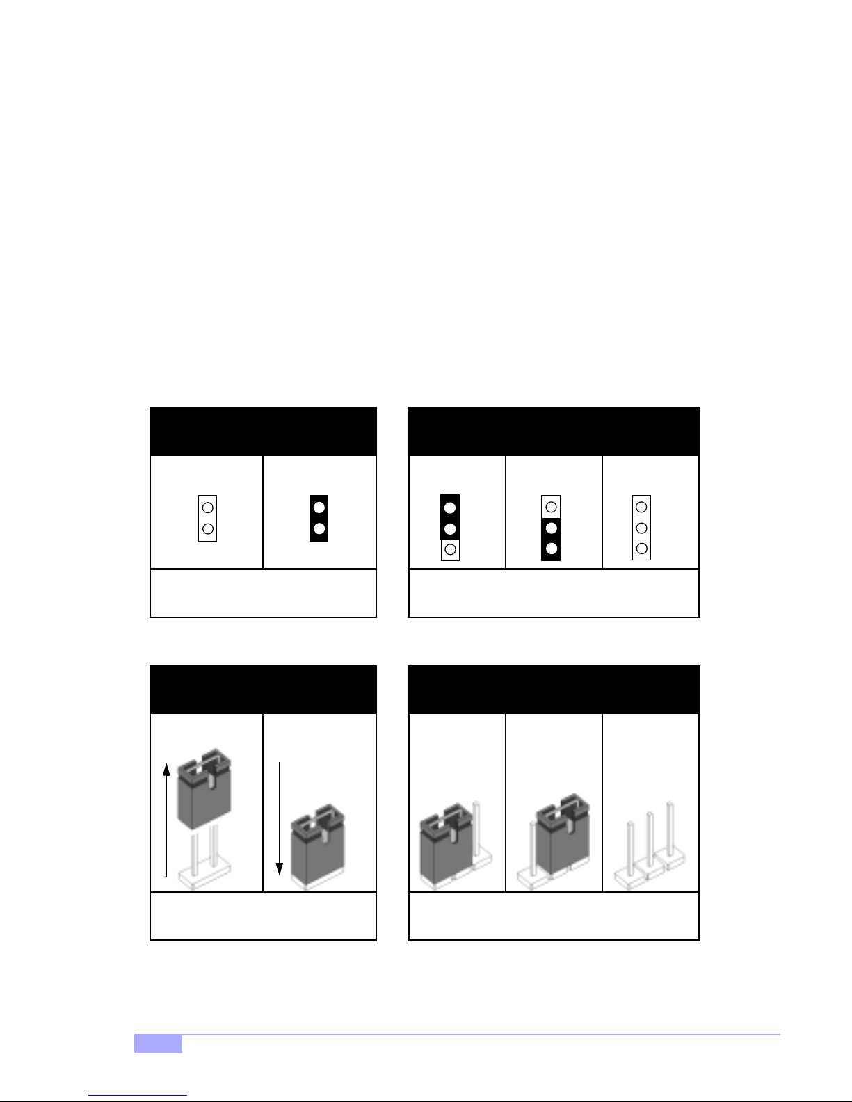
In this manual, the term “closed” and “on” are used when referring to jump ers (or jumper pins) th at are
active; “open” a nd “off” a re u sed whe n re fer ri ng to ju mp ers (or jumper pin s) that are inactive. S ee Figure
2.0a and Figure 2.0c for examples o f “on” and “off” pins and jumpers.
Jumpers and pins are con nected by slipping the plasti c jumper connector over the top of two adjacent
jumper pins ( indicated by 1- 2 or 2-3). The met al rod inside t he plastic sh ell b ridges the ga p betw een the
two pins, completin g the circuit. See Figure 2 .0b and Figure 2.0d for more examples of 3-pin jumper
connections. NOTE: The small number “1” indicates pin 1.
The tables and maps on the following p ages will help you set the jum pers for CPU speed, infr ared, and
external connector pin assignments, among others. The miniature motherboard maps will help you locate
the jumpers on your board. Full page maps of the motherboard can be found on the next two pages.
2-pin jumpers
off on
Figure 2.0a
(overhead view)
1-2 2-3 open
3-pin jumpers
1
2
3
Figure 2.0b
(overhead view)
1
2
3
2-pin jumpers 3-pin jumpers
1-2 2-3 openoff on
1
2
3
Figure 2.0c
(front angle view)
10
11
Figure 2.0d
(front angle view)
http://www.tyan.com
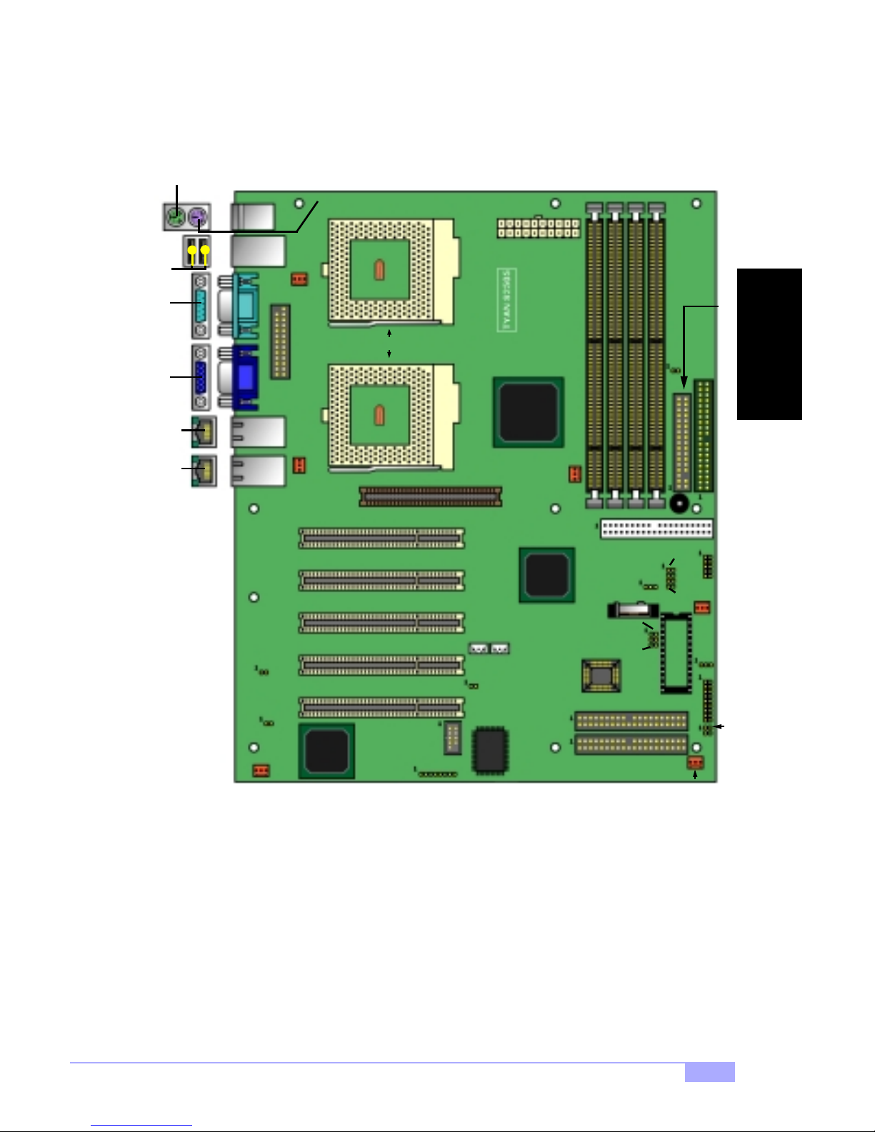
2.5 Map of Motherboard Jumpers
Keyboard port (lower port)
Mouse port
(upper port)
USB
Serial
Ports
port
FAN2
ATX Power
Connector
INSTALL
Video
LAN
LAN
FAN1
ATI™
ZIF Socket370
2x/4x AGP slot
COM1
J16
VIA
VT82C694X
chipset
J7*
J8*
JP16
Promise™
FastTrak100
FAN3
Battery
2 Mbit
Flash
RAID Primary IDE
RAID Secondary
JP1*
Secondary IDE
JP7
JP8
JP6
JP18*
JP19*
JP20*
IDE
JP9
JP10
D35*
FAN6
J15
FDD Connector
Primary IDE
USB2
FAN4
D28
J12
JP14
PJ2
port
Port
(J4)*
Port
(J5)*
J10*
JP3
Rage XL
FAN5
* indicates an optional feature available on some Tiger 200 S2505 models
** JP7, JP8, JP9, and JP10: under qualification at time of print, check Tyan website for updates:
http://www.tyan.com
Tiger 200 S2505
11
2.6 Setting Jumpers
2.6-A. Front Pa nel Connector (J12)
VCC
LED
HDD
Reset
Infrered
2.6-B. CMOS Reset (JP6)
LED
Ground Switch
Switch
Switch
IR +5V
IR RX
Ground
IR TX
CHIN2
1-2
12
34
56
78
910
11 12
1314
1516
1718
Pwr LED+
Slp LED+
Ground
SN_NMI
VCC
no connect
no connect
Speaker
2-3
LEDs
Pwr/Slp
Power
Switch
*Power LED:
for 3-pin
(bi-color/
single-color)
LED, use D28,
located above
J12
FAN2
FAN1
FAN5
USB2
JP16
FAN3
JP6
FAN4
D28
J12
FAN6
JP6
Normal
If you have been locked out o f your system beca use you forgot your password or set the CMOS incorrectly, or have just finished flashing your BIOS follow the instructions below.
By following this procedure, you will erase your password and reset the CMOS.
Clear
1. Power off the system, and disconnect the power supply
2. Close pins 2-3 on JP6 (see mini-map for locat i on of JP6)
3. Wait about three seconds
4. Move jumper back to 1-2, then power on the system again
2.6-C. USB Connector (USB2)
This connector is for the additional USB connector* (which adds 2 more ports on a second USB channel).
2.6-D. Cooling Fans (FAN1, FAN2, FAN3, FAN4, FAN5, FAN6)
1
2
3
FAN
Ground
In addition to installing your CPU, Tyan highly recommends that you install a CPU fan/heatsink combina-
tion, and if n eeded, addi tional ch assis fans . To this end Tyan has provided several connectors to power
the fan(s), as well as the fan pinout (shown above). Here is some information you may find useful:
- We recommend you use FAN1 and FAN2 for the CPU cooling fans
- All other fan connectors are left to the user’s discretion
2.6-E. RAID Enable/Disable (JP16)
close
+12V
open
Speed
JP16
enable
Y ou can enable or disable the onboard IDE RAID by using this jumper. The settings are shown in the table
above.
* extra accessories can be purchased at the Tyan Online Store: http://www.etyan.com
12
disable
http://www.tyan.com
2.6-F. RAID IDE ports (RAID PIDE, RAID SIDE)
These are the IDE RAID ports. Their functionality is determined by J25 (see Section E, p. 12).
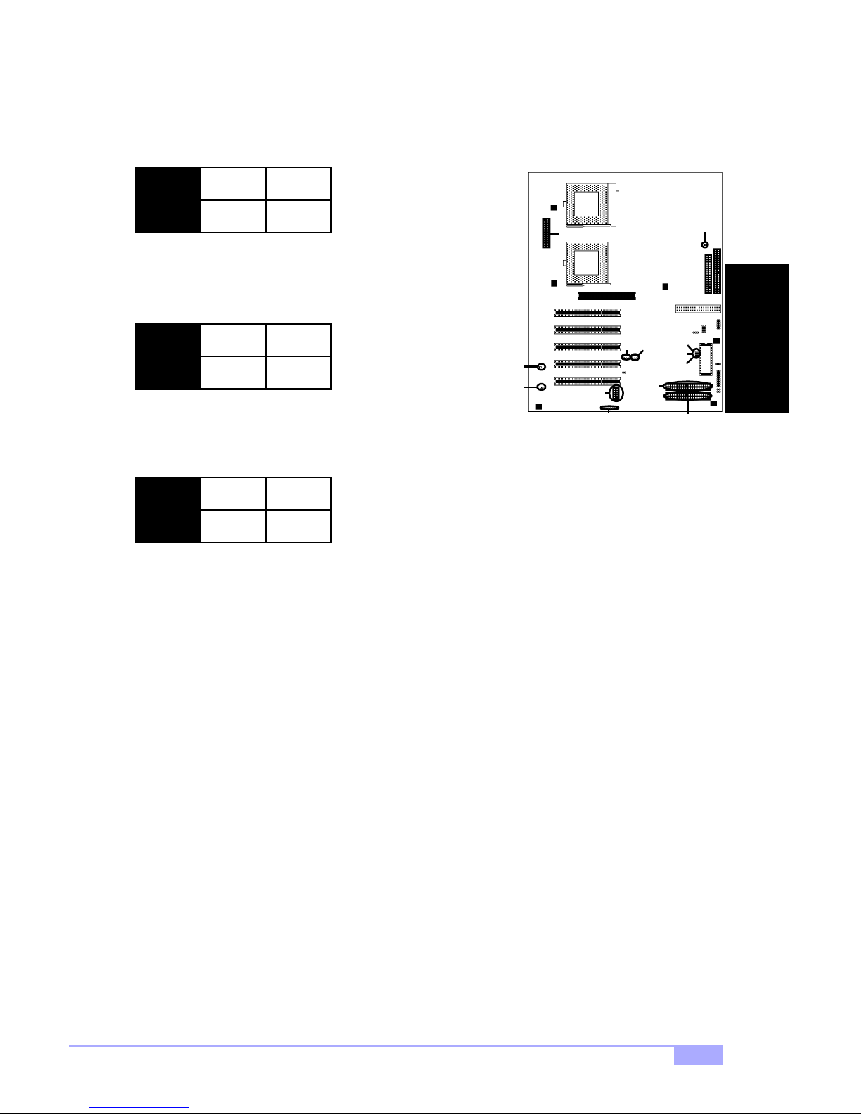
2.6-G. Onboard Video Enable/Disable (JP3)
close
open
JP3
disable
You can enable or disable the onboard video controller by
using this jumper. The settings are shown in the table above.
2.6-H. AGP IRQ Enable/Disable (J10)* *
close
J10
disable
You can enable or disable the AGP IRQ by using this jumper.
The settings are shown in the table above.
2-6-I. Auto CPU Frequency Jumper (JP1)**
close
enable
open
enable
open
J10
JP3
PJ2
COM1
J16
J7
RAID
PIDE
J8
J18
J19
J20
RAID
SIDE
JP1
D35
JP1
auto-detect
Default is for JP1 is AUTO-DETECT. NOTE: The CPU frequency is dependent on the CPU’s pre-set bus
frequency. Tyan takes no liability for damage related to the incorrect setting of the jumper.
100 or 133
INSTALL
2.6-J. Infrared connector (J16)
This is the connector for an infrared device.
2.6-K. Serial Port con ne cto r (COM1)
This is the connector for a second serial port.
2.6-L. Parallel Port (PJ2)*
This is the connector for a parallel port*. It has been provided should you decide to add an external parallel port.
2.6-M. Option (D35)**
This is an optional reserved socket, available on some Tiger 200 S2505 models.
2.6-N. Option Jumpers (J18, 19, J20) **
These are optional jumpers, related to D35’s function.
2.6-O. Wake on LAN (J7)**, Wake on Ring (J8)**
For WOL and WOR functions (respectively). Check Tyan website for details: http://www.tyan.com
* extra accessories can be purchased at the Tyan Online Store: http://www.etyan.com
** optional feature available on some models of Tiger 200 S2505
Tiger 200 S2505
13

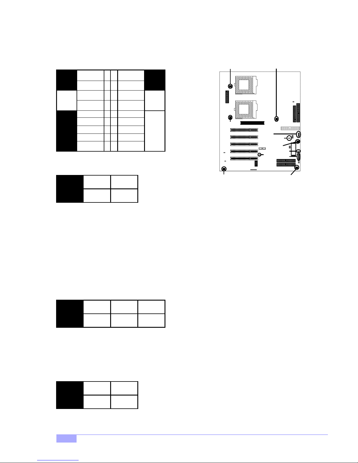
2.6-P. CPU Frequency Settings (JP7, JP8, JP9, JP10)**
NOTE: The following settings are only valid if a non-retail/engineering sample CPU is installed. On retail
CPUs, settings will automatically be detected and used accordingly.
Ratio
2
3
4
5
5.5
7.5
9.5
11.5
2.6-Q. Soft Power Connector
The soft power co nne ctor i s p art of j ump er bloc k J12 (p i ns 6 to 8). Th i s bo ar d us es th e chipset for power
management, inclu ding turning on and off the system. If the power button function option in the BIOS
Power Managemen t menu i s set to “On/ Off” (which is t he defaul t), pressin g the power button on ce after
the BIOS has booted up will turn the syste m on and off. If the power button function is set to Suspend,
pressing the power button once will wa ke up the system or send it to Suspend mode. In this case, you
cannot turn the syste m off unless you sh ut down t hrough the Windows op erating system o r you hold the
power button down for four seconds.
Bus
Speed
100
133
100
133
100
133
66
100
133
66
100
133
66
100
133
66
100
133
66
100
133
CPU
Speed
200
333
300
433
400
533
333
500
667
366
550
733
500
750
997
633
950
1264
733
1150
1530
JP7 JP8 JP9 JP10
ON
ON
ON ON ON
OFF
ON ON
OFF OFF
OFF
ON ON ON
OFF
ON ON ON
OFFOFF
OFF
ON ON
ON ON
OFFON ON ON
OFF
ONOFFOFF
2.6-R. Hardware Reset Switch Connector Installation
The reset switch on your chassis case provides you with the Hardware Reset function, which is the same
as power on/off, except that the system will immediately execu te a cold start after the reset button is
pushed.
2.6-S. Flash Utility
You can upgrade t he BIOS of this mo therboard by using t he Flash Utility (se e p. 38). Check the Tyan
website for details: http://www.tyan.com
* check the Tyan website for updates: http://www.tyan.com
** under qualification at time of printing, check the Tyan website for updates: http://www.tyan.com
14
http://www.tyan.com
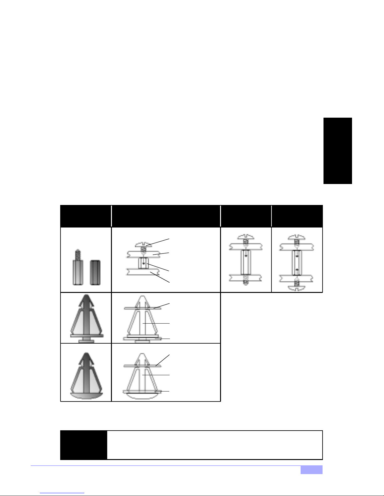
2.7 Mounting the Motherboard into the Chassis
Your chassis may include moun ting hardwar e. If mounting hardware was included, yo u can use the fo llowing examples to help you in installing your motherboard into the chassis.
The chassis may h ave com e with th e studs integrated in to t he cha ssis wa ll, so in t hose ca ses you wou ld
only need to us e scre ws (possib ly inclu ded wi th you r chass is) to i nstall th e mot herboa rd. S ee the examples (Figure 2.0, shown below) for more details.
If the chassis includes mounting hardware without the studs pre-installed, then you will need to install the
motherboard usin g the mounting hardware as sho wn in the examples below. Remember not to overtighten any of th e screws, or you migh t risk breaki ng intern al traces i n the surroun ding ar ea, or dam age
the motherboard in some other way.
Other examples of how to install your motherboard using other hardware (that may or may not have been
included with your chassis) are shown below.
One solution for installing motherboardType of hardware Another solution Another solution
screw
motherboard
base
stud
chassis wall
motherboard
base
INSTALL
The diagrams above are only representative of a few solutions for installing a
NOTE:
motherboard into the chassis. The installation procedure for installing your m otherboard may differ.
Tiger 200 S2505
standoff
chassis wall
motherboard
base
standoff
chassis wall
Figure 2.0
15
2.8 Installing Memory
Please keep in m i nd t hat a lthough some mem or y m od ul es m ay ap pe ar to b e hi gh -q uali ty, they may contain inferior or substandard p arts. The type o f memory you ch oose to instal l should be checke d against
the memory compatibility list, which is available from Tyan’s website at http://www.tyan.com
Memory Installation Procedure
Here are some details of memory installation for this board:
At least one unbuffered DIMM must be installed for the system to POST.
The motherboard supports 64MB, 128MB, 256MB, and 512MB PC100/133* SDRAM.
All installed memory will be automatically detected, so there is no need to set any jumpers.
The motherboard supports up to 1.5 (3 DIMMs)* or 2 GB (4 DIMMs)* of memory.
Insert the DIMM by pushing the modul e into the socket wit h even force. Do not insert one
Step
1
end and then the ot her: instal l the whole module at onc e or you m ight bend the DIMM pin s.
Make sure the DIMM is securely seated.
Line your module up so that the pins fit into the socket. There is only one way your DIMM can
Step
2
fit properly. Make sure that the short row of pins is lined up with the short gap in the DIMM
socket.
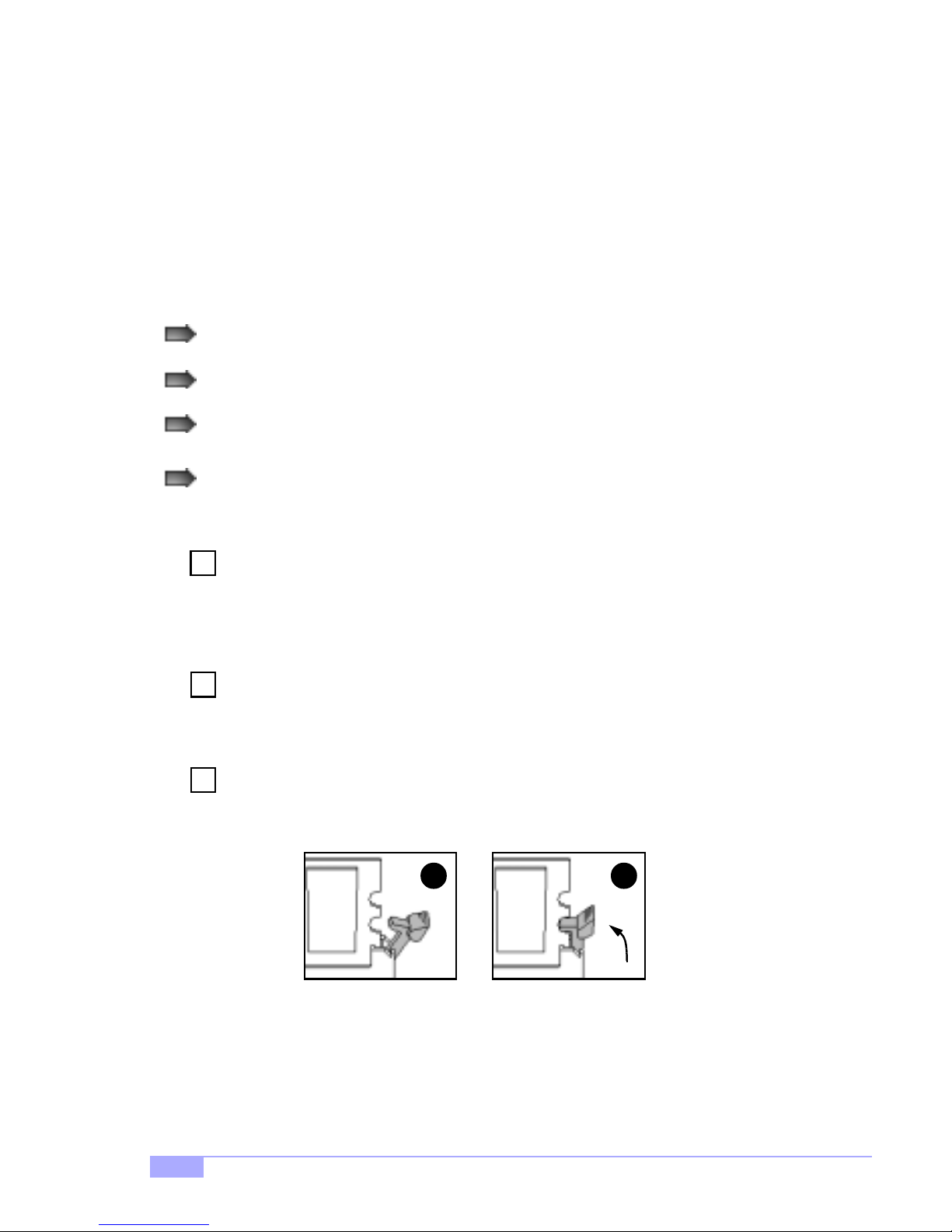
Lock the DIMM into plac e by pushing the clips back on either end of the socket onto the
Step
3
notches in the ends of the DIMM (see pictures below for details).
1
* 2.0GB total memory @ 4 DIMMs only, when using 100MHz SDRAM
1.5GB total memory @ 3 DIMMs only, when using 133MHz SDRAM
Check the Tyan website for details on memory compatibility: http://www.tyan.com
2
16
http://www.tyan.com
Removing a DIMM
Removing a DIMM is just the reverse : si mply pu l l back the clips fro m the D IM M (see pictur es belo w), and
carefully pull the module straight out. Place the DIMMs in an anti-static bag as soon as you remove them
to avoid static damage.
21
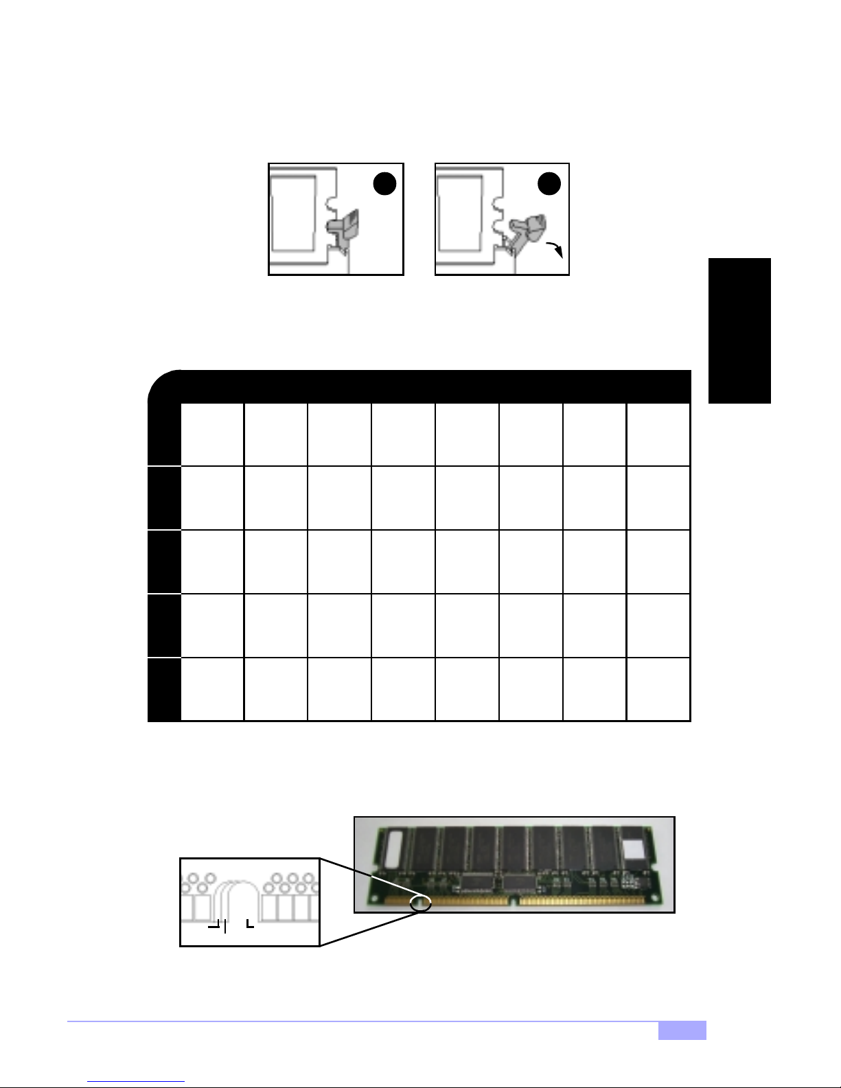
Suggested Memory Confi g ur at ion s
The table below shows some of the possible memory configur ations. Not all poss ible configurations
are listed. Your memory configuration may differ from one or more of the combinations shown below.
2GB* at 100 MHz combination or 1.5GB* at 133 MHz combination
INSTALL
64MBx1
DIMM 1DIMM 2DIMM 3DIMM 4
0
0
0
64MB
TOTAL
The 168-pin DIM Ms (Du al In- l ine M em ory M odu les) must be of th e 3.3V PC100/PC133 varie ty. The position of the notch in the SDRAM key position will tell you whether or not a DIMM is unbuffered (see Figure
2.1 below). All installed memory will be automatically detected, so there is no need to set any jumpers.
0
64MBx1
0
64MBx1
128MBx1
0
64MBx1
0
192MB 256MB
128MBx1
128MBx1
0
0
0
256MBx1
0
128MBx1
384MB
0
0
512MBx1
512MBx1
1024MB
512MBx1
0
1024MBx1
0
1536MB
0
1024MBx1
0
1024MBx1
2048MB128MB
RFU
buffered
* 2.0GB total memory @ 4 DIMMs only, when using 100MHz SDRAM
1.5GB total memory @ 3 DIMMs only, when using 133MHz SDRAM
Check the Tyan website for details on memory compatibility: http://www.tyan.com
unbuffered
Tiger 200 S2505
Figure 2.1
17
 Loading...