

TYAN S2466 User Manual

1
http://www.TYAN.com
Tiger MPX
///
S2466
Revision 1.2
Copyright © TYAN Computer Corporation, 2001-2002. All rights reserved. No part of this manual
may be reproduced or translated without prior written consent from TYAN Computer Corp.
All registered and unregistered trademarks and company names contained in this manual are
property of their respective owners including, but not limited to the following.
TYAN, Tiger MPX S2466 are trademarks of TYAN Computer Corporation.
AMD, Athlon, 760MP, 760MPX and combinations thereof are trademarks of AMD Corporation.
Phoenix, Phoenix BIOS are trademarks of Phoenix Software.
Microsoft, Windows are trademarks of Microsoft Corporation.
IBM, PC, AT, PS/2 are trademarks of IBM Corporation.
Winbond is a trademark of Winbond Electronics Corporation.
Portable Document Format (PDF) is a trademark of Adobe Corporation.
Information contained in this document is furnished by TYAN Computer Corporation and has been
reviewed for accuracy and reliability prior to printing. TYAN assumes no liability whatsoever, and
disclaims any express or implied warranty, relating to sale and/or use of TYAN products including
liability or warranties relating to fitness for a particular purpose or merchantability. TYAN retains the
right to make changes to product descriptions and/or specifications at any time, without notice. In
no event will TYAN be held liable for any direct or indirect, incidental or consequential damage,
loss of use, loss of data or other malady resulting from errors or inaccuracies of information
contained in this document.

2
http://www.TYAN.com
Table of Contents
Before you begin…………………….…………….
Chapter 1: Introduction…………….……………..
1.1 Congratulations
1.2 Hardware Specifications
1.3 Software Specifications………………
Chapter 2: Board Installation…………………….
2.0 Board……………………………………
2.1 Jumper Layout………………………...
2.2 Front Panel Connector………………..
2.3 CMOS Reset…………………………..
2.4 CPU FSB Jumpers……………………
2.5 Force 33MHz PCI Bus………………..
2.6 Disable/Enable LAN (Optional)………
2.7 Secondary USB Connector…………..
2.8 SMBus Connector…………………….
2.9 Chassis Intrusion Header…………….
2.10 Front Panel LAN Activity LED………..
2.11 Drive Power Auxiliary Connector……
2.12 FAN Connectors………………………
2.13 Mounting the Motherboard…………..
2.14 Installing Memory……………………..
2.15 Installing the CPU and Cooling Fan…
2.16 Attaching Drive Cables……………….
2.17 Installing Add-in Cards………………..
2.18 Connecting PS/2, USB, Serial……….
2.19 Connecting the Power Supply……….
2.20 Finishing Up……………………………
Chapter 3: BIOS Setup…………………………...
3.1 Main Setup……………………………..
3.2 Advanced……………………………….
3.3 Chipset………………………………….
3.4 Keyboard……………………………….
3.5 I/O……………………………………….
3.6 PCI………………………………………
3.7 PCI/PnP IRQ Exclusion……………….
3.8 PCI/PnP UMB Exclusion……………...
3.9 Security…………………………………
3.10 Power…………………………………...
3.11 Boot……………………………………..
3.12 Exit……………………………………..
Chapter 4: System Resources…………………...
4.1 Beep Codes……………………………
4.2 Flash Utility…………………………….
Appendix I: Glossary……………………………..
Technical Support…………………………………
……………………………………………..Page 3
……………………………………………Page 5/6
……………………………………………..Page 6
……………………………………………..Page 7
……………………………………………..Page 8
..……………………………………………Page 9
……………………………………………Page 10
……………………………………………Page 11
……………………………………………Page 12
………………………………………..Page 13/14
..………………………………………Page 15/17
……………………………………………Page 17
……………………………………………Page 18
……………………………………………Page 20
……………………………………………Page 21
………………………..………………Page 22/23
……………………………………………Page 23
……………………………………………Page 24
……………………………………………Page 25
..………………………………………Page 25/26
……………………………………………Page 26
……………………………………………Page 27
……………………………………………Page 28
……………………………………………Page 33
3
http://www.TYAN.com
Before you begin…
Check the box contents!
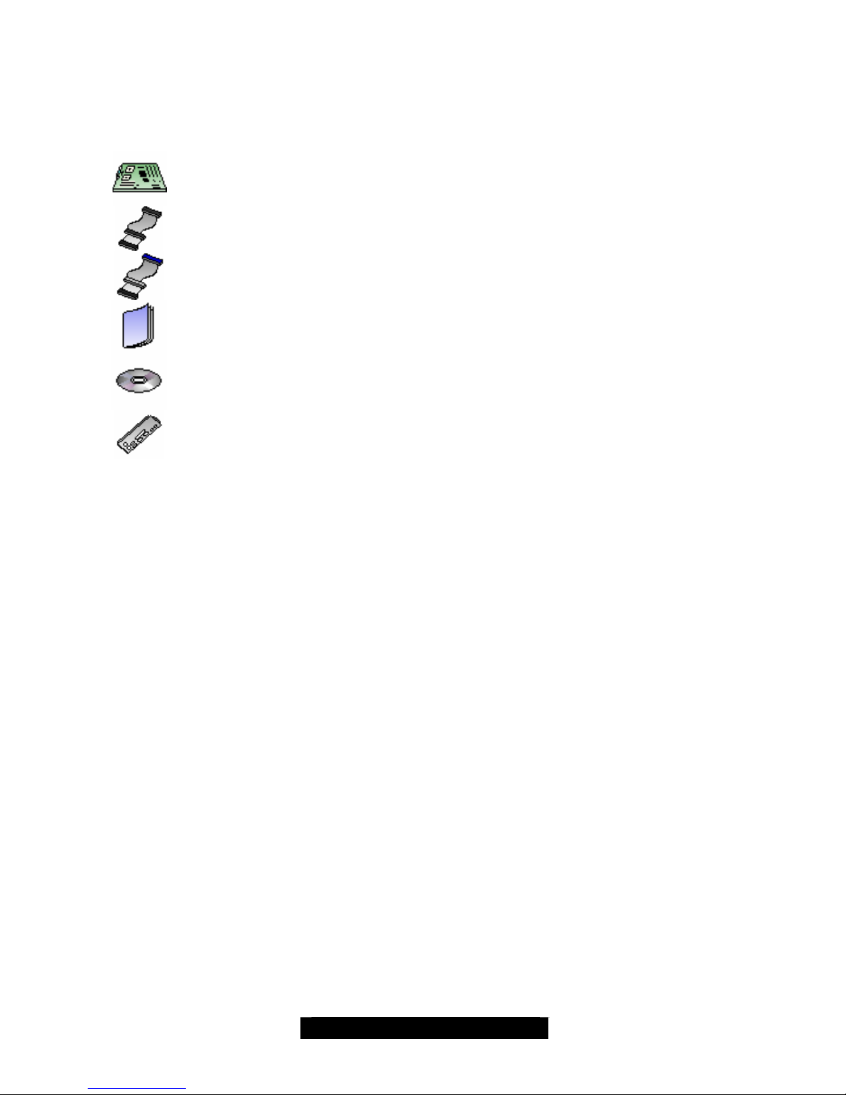
The retail motherboard package should contain the following:
1x Tiger MPX motherboard
1x 34-Pin floppy drive cable
1x Ultra-DMA-100/66 IDE cable
1x Tiger MPX user’s manual
1x TYAN driver CD
1x I/O shield with 1 LAN ports (optional)
If any of these items are missing, please contact your vendor/dealer for replacement before
continuing with the installation process.

4
http://www.TYAN.com
Chapter 1: Introduction
1.1 – Congratulations!
You’re now the owner of the most advanced dual AMD processor solution – Tiger MPX. Based on
the AMD 760MPX chipset, the Tiger MPX offers you all the latest features of a cutting-edge
platform along with the security of having the most reliable computing platform. Supporting Athlon
MP processors (and Athlon XP processors in single mode), the Tiger MPX opens a whole new
computing dimension. Whether operating in single mode or symmetrical processing mode, Tiger
MPX offers a plethora of expansion options previously unavailable.
Tiger MPX is an integrated motherboard with features such as dual channel UltraATA-100, and
optional 10/100Mbit Ethernet. Users who demand the most in speed and bandwidth will
appreciate the native support for 64-bit, 66MHz PCI slots as well as 32-bit, 33MHz PCI and 4X
AGP.
Offering features that supercede the competition, Tiger MPX enables connectivity right out of the
box. Using the optionally equipped 10/100Mbit Ethernet port, you’re able to get connected in no
time at all. Whether it’s to the Internet or a LAN, Tiger MPX has you covered in virtually all
directions.
The Tiger MPX supports up to 4GB* of Registered ECC PC2100/1600 DDR SDRAM.
*The AMD -760 MPX requires a portion of memory to be reserved for PCI devices. Allocation for these devices is
dependent on the number of PCI devices installed, and option ROM for each device. Common configurations
will see 3.5GB to 3.8GB of available memory.
Remember to visit TYAN’s Website at http://www.tyan.com. There you can find information on all
of TYAN’s products with FAQs, distributors list and BIOS setting explanations.
1.2 – Hardware Specifications
Processor
• Dual PGA462 ZIF sockets
• Supports single AMD Athlon MP (single or
dual) and Athlon XP (single only) processors
• Two onboard VRMs
• Front-side bus support for 200/266MHz
Chipset
• AMD 760MPX Chipset
• AMD 762 System Controller
• AMD 768 Peripheral Bus Controller
• Winbond 83627 Super I/O ASIC
Memory
• Four 2.5v 184-pin DIMM sockets
• Supports up to 4GB* of Registered
PC2100/1600 DDR SDRAM (DIMM slots 1
and 2 may be used for up to 2GB of
Unregistered/Unbuffered memory)
• Supports ECC (72-bit) memory
Expansion Slots
• 2 64-bit/66MHz (both 3.3v) PCI slots (v2.2
Spec)
• 4 32-bit/33MHz 5v PCI slots (v2.2 Spec)
• 1 4X AGP slot (also accepts 1X and 2X AGP
cards)
Integrated PCI IDE
• Dual-channel UItraATA-100
• Up to four E-IDE drives
• Support for PIO/DMA/ATAPI devices
Integrated I/O
• One floppy connector supports up to two
drives
• Two 9-pin 16550-based serial ports
• One 25-pin SPP/ECP/EPP parallel port
• Four USB v.1.1 ports (two via optional cable)
• PS/2 keyboard and mouse ports
• One RJ-45 LAN port with LEDs (optional)

5
http://www.TYAN.com
Hardware Monitoring
• Winbond W83782D hardware monitoring
ASIC
• CPU Temp, voltage and fan monitoring
Form Factor
• ATX footprint (12” x 10.2”, 304.8mm x
259.08mm
• One 20-pin + 4-pin ATX12V power
connector set
• 4-pin Auxiliary power connector
• Two Serial ports
• Stacked USB (two) ports
• One RJ-45 LAN port with LEDs (optional)
Integrated LAN (Optional)
• 3COM 3C920C LAN controller (with 3C905
driver set)
• 10/100Mbps max data rate per controller
BIOS
• Phoenix 2 or 4Mb BIOS Flash ROM
• Auto-configure IDE drive types
• Multiple boot options
• DMI 2.0 compliant
Regulatory
• FCC DoC (declaration of Conformity)
• European Community of CE (declaration of
Conformity)
1.3 – Software Specifications
OS (Operating System) Support
• Microsoft Windows NT 4
• Microsoft Windows 2000
• Microsoft Windows XP
• Professional
*TYAN reserves the right to add support or
discontinue support for any OS with or without
notice.
*The AMD-760 MPX requires a portion of memory to be reserved for PCI devices. Allocation for
these devices is dependent on the number of PCI devices installed, and option ROM for each
device. Common configurations will see 3.5GB to 3.8GB of available memory.

6
http://www.TYAN.com
Chapter 2: Board Installation
Installation
You are now ready to install your motherboard. The mounting hole pattern of the Tiger MPX
matches the ATX system board specifications. Your chassis should support a standard ATX
motherboard form factor.
How to install our products right… the first time
The first thing you should do is read this user’s manual. It contains important information which will
make configuration and setup much easier. Here are some precautions you should take when
installing your motherboard:
(1) Ground yourself properly before removing your motherboard from the antistatic bag.
Unplug the power from your computer power supply and then touch the power supply.
For the safest conditions, TYAN recommends wearing a static safety wrist strap.
(2) Hold the motherboard by its edges and do not touch the bottom of the board.
(3) Avoid touching the motherboard components, IC chips, connectors, and leads.
(4) Avoid touching memory module contacts and IC chips
(5) Place the motherboard on a grounded antistatic surface or on the antistatic bag from
which it came in.
Having reviewed the precautions above, the next step is to take the motherboard out of the
cardboard box and static bag, hold it by its edges and place it on a grounded antistatic surface,
component side up. Inspect the board for damage.
The following pages will detail for you on how to install your motherboard into your chassis, install
processor(s), memory, hard drive and floppy cables/drives and heatsinks.
NOTE DO NOT APPLY POWER TO THE BOARD IF IT HAS BEEN DAMAGED
7
http://www.tyan.com
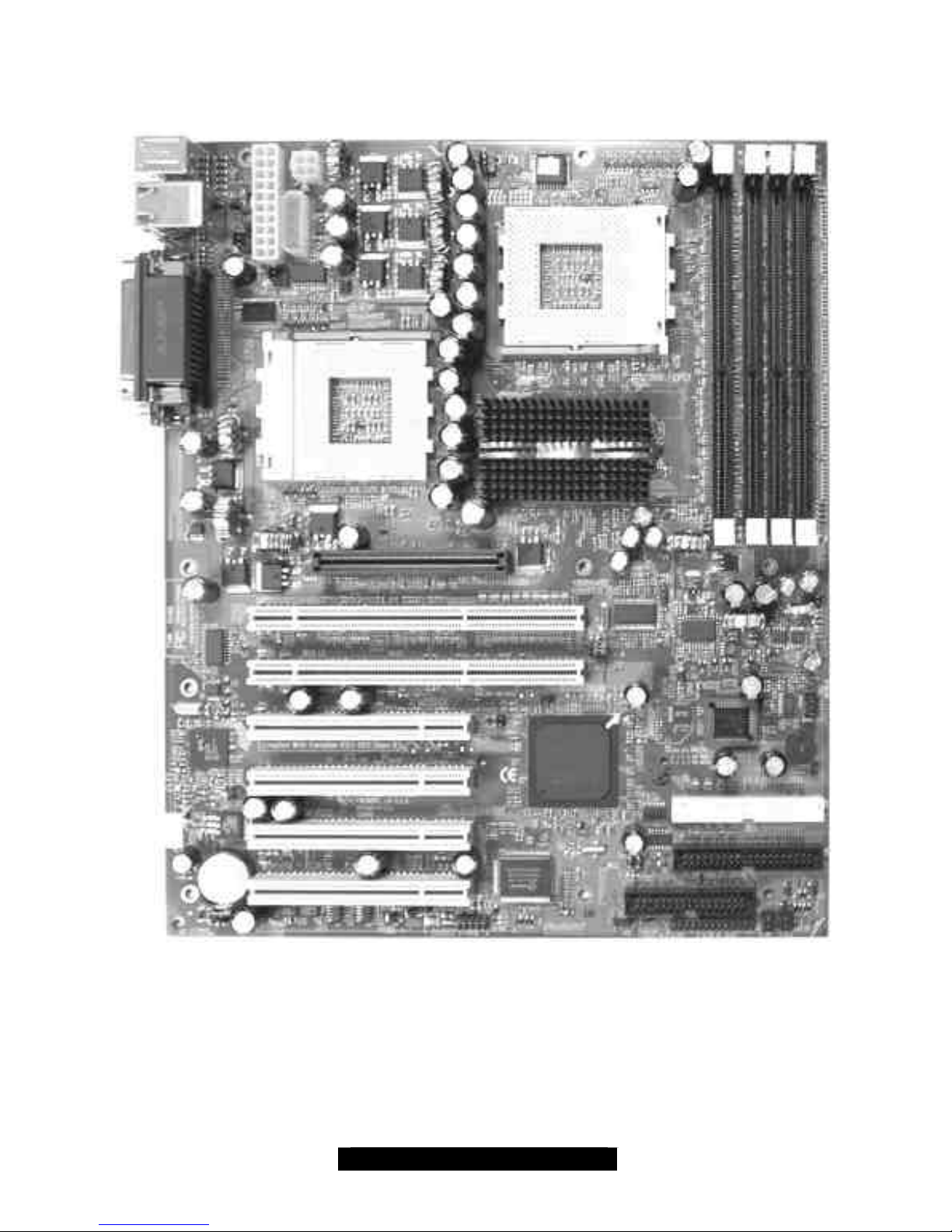
2.0 – Board
The following is an image of the S2466 Tiger MPX.
The above photograph is only a representation of the actual board. Because boards tend to
be updated and go through different revisions, certain components may change and or be
repositioned. The picture above may or may not look exactly like the board you received.
The following page will detail vital components of this board.
8
http://www.tyan.com
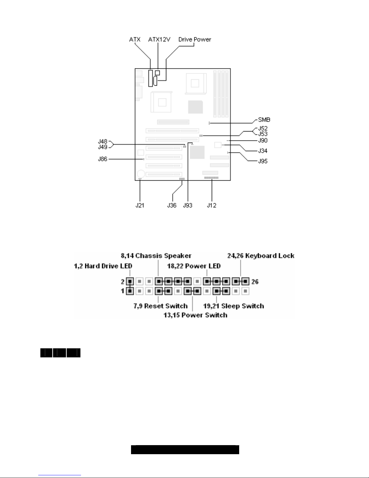
2.1: Board Jumpers
2.2 Front Panel Connector (J12)
Your chassis will usually come with connectors to install onto the motherboard, such as HDD and
P ower LEDs. The Front Panel Connector (J12) has been implemented for such purposes.
2.3 – CMOS Reset (J21)
1 2 3
1,2: Default
2,3: Connect pins 2 and 3 together to reset the CMOS settings in case an incorrect
setting causes system instability or you have forgotten your system/setup password
of have just flashed your BIOS.
Power off the system and disconnect the power supply from the motherboard.
- Close pins 2 and 3 on J21
- Wait about 5 seconds
- Close pins 1 and 2 on J21
- Reconnect the power supply and power on the system

9
http://www.tyan.com
2.4 – CPU Front Side Bus Jumpers (J48, J49, J52, J53)
NOTE: YOU MUST SET THESE JUMPERS AT THE SAME SPEED TO EACH OTHER IN
ORDER TO PROPERLY OPERATE THE TIGER MPX. THIS IS REGARDLESS OF WHETHER
THERE IS ONE OR TWO PROCESSORS INSTALLED.
TYAN will not be liable should damage be caused by not properly setting these jumpers, or any other jumpers.
TYAN will not take responsibility if improper and incompatible processors are used on this board. Please refer to
our website for the lat est processor compatibility charts. You may also refer to the specifications page for the
Tiger MPX in this manual.
266MHz 200MHz
J52 2-3 1-2
Connect pins 2/3 on J52, and 2/3 on J53 to set the FSB speed to
266MHz.
J53 2-3 2-3
Connect pins 1/2 on J52, and 2/3 on J53 to set the FSB speed to
200MHz.
266MHz 200MHz
J48 1-2 2-3
Connect pins 1/2 on J48, and 1/2 on J49 to set the FSB speed to
266MHz.
J49 1-2 2-3
Connect pins 2/3 on J48, and 2/3 on J49 to set the FSB speed to
200MHz.
TIP: Setting both jumpers to operate at 266MHz will ensure safe and proper operation regardless
of whether the processor(s) installed operate at 200MHz or 266MHz.
2.5 – Force 33MHz PCI Bus (J93)
1 2
On: Force PCI to operate at 33MHz
Off (default): PCI operates at 66MHz
2.6 – Disable/Enable LAN (J86) – (Optional Feature)
1
2
Closed (default): LAN port is disabled.
Open: LAN port is enabled.
TIP: Set the LAN port on or off before installing expansion cards so that they don’t get in the way
of the jumper. Also, the 3C905C 3COM Ethernet controller is a high quality, high efficiency
solution. TYAN recommends using the 3COM controller instead of installing a separate Ethernet
card.
2.7 – Secondary USB connector (J36)
5 4 3 2 1
1 2 3 4 5
Use this connector to attach a rear panel or front chassis USB ports. Front
chassis USB ports are dependant on the chassis used and the
manufacturer that makes them. Check your chassis manufacturer’s website
for models that include front USB ports.
TIP: For convenience, look for a compatible chassis that also includes USB connectors. This will
provide a convenience if you should ever need to connect devices like digital cameras or other
USB devices.
2.8 – SMBus connector (SMB)
1
2
3
This connector is reserved for diagnostics functions usually used by system
integrators and OEMs (Original Equipments (or Electronics) Manufacturer). Do not
tamper with this header.
10
http://www.tyan.com
2.9 – Chassis Intrusion header (J90)
1 2
This header allows you to connect a chassis intrusion mechanism that turns on an alarm
or in certain cases, prevents the computer from being started. This feature is only found
on certain types of server or high end workstation class chassis and is usually only
accessible through server management software.
2.10 – Front Panel LAN Activity LED (J95)
1
2
Use this header to connect a front panel chassis LED that will light up upon LAN
activity.
2.11 – Drive Power (J98)
This Auxiliary drive power connector is a standard 4-pin ATX drive connector. You may use any
corresponding drive power connector for J98. It is recommended that you use this connector if you
do not have an ATX12V power supply which uses a square 4-pin 12V connector.
NOTE The S2466 Tiger MPX auxiliary drive power connector must be independent of
any other devices. A device such as a DVD/CD-ROM drive, hard drive, or any
other devices cannot be attached onto the same power line. If connected, system
stability is compromised.
TIP: Connecting all three power connectors (the 20-pin ATX, 4-pin Auxiliary and 4-pin ATX12V)
will not damage the motherboard and the system will operate normally, however connecting all
three is not necessary.
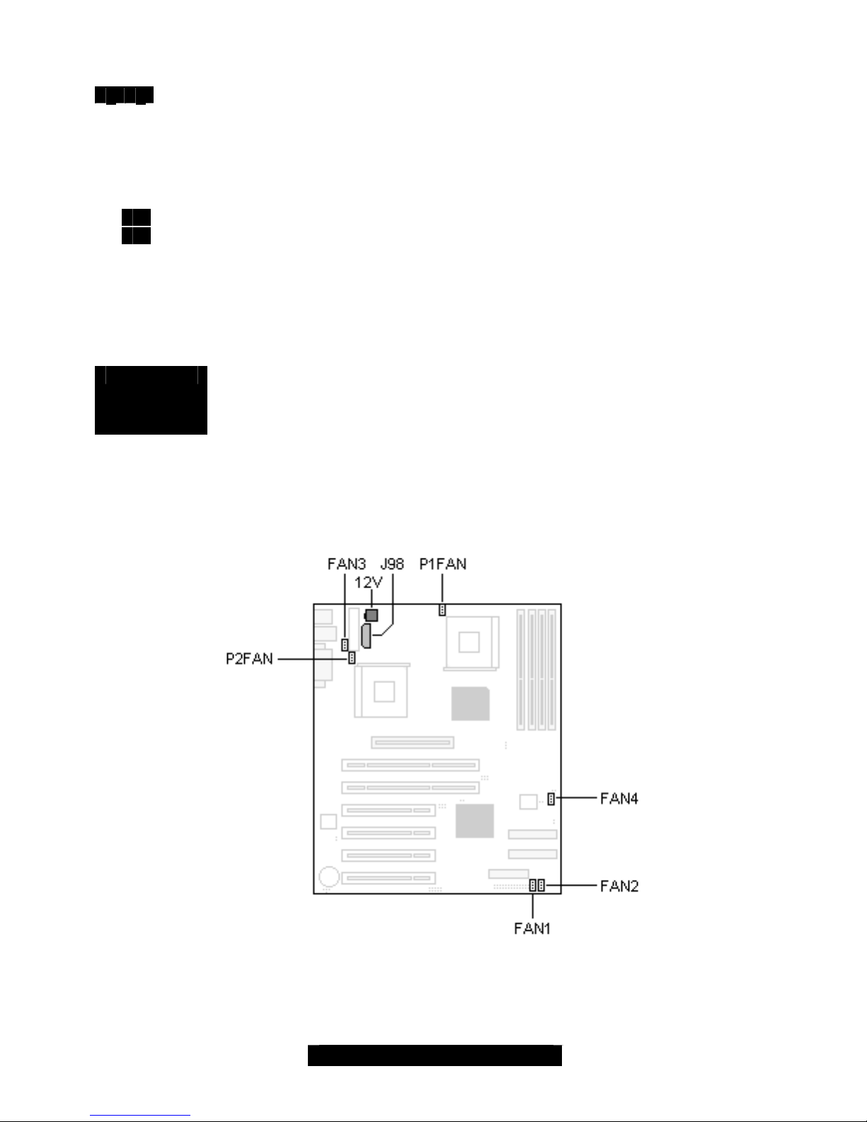
2.12 – FAN connectors
FANs 1 to 4 are used for chassis cooling while P1 FAN and P2 FAN are used to attach processor
fans. To ensure safe and reliable operation, do not mix and match chassis fans connectors with
the P1FAN/P2FAN connectors.
11
http://www.tyan.com
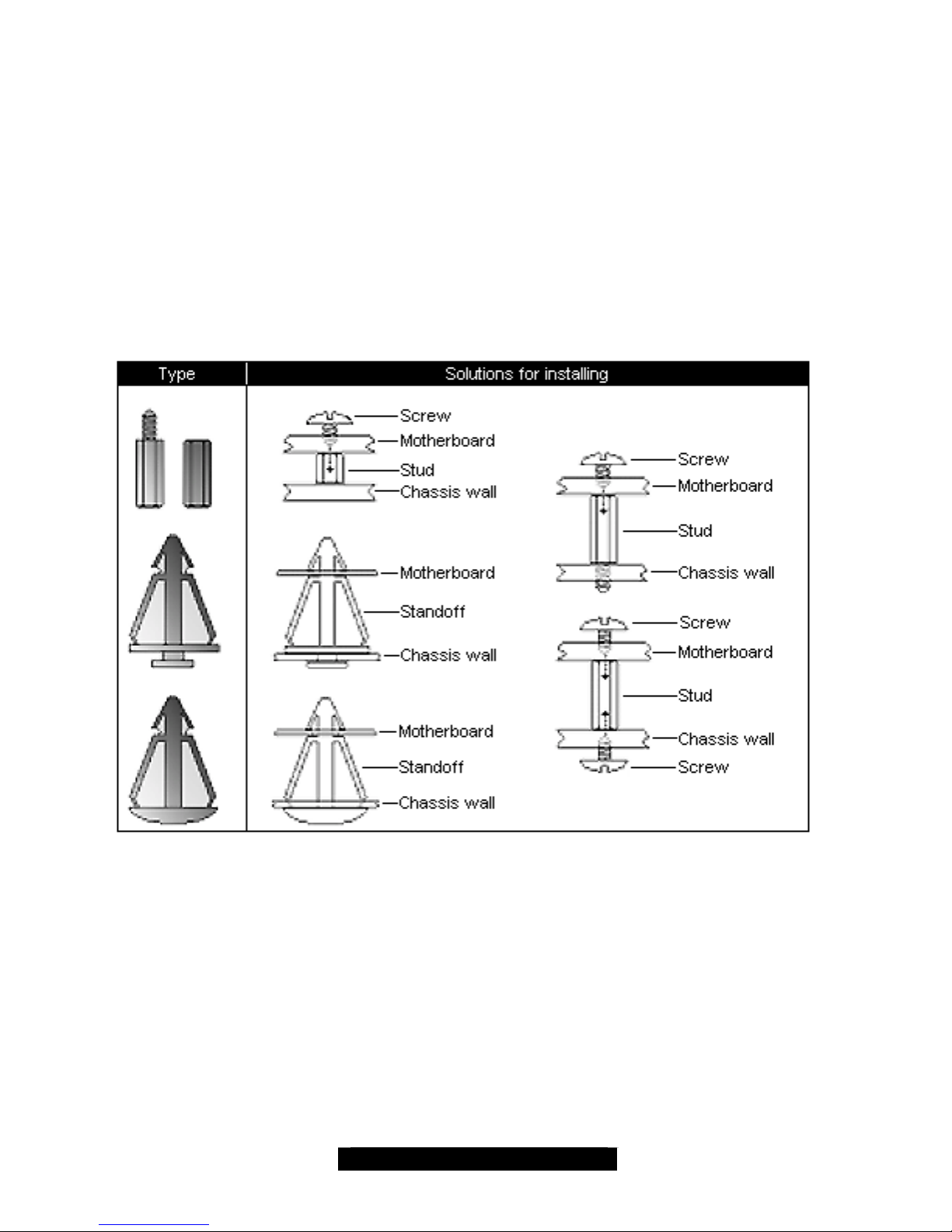
2.13 – Mounting the Motherboard
Before installing your motherboard, make sure your chassis has the necessary motherboard
support studs installed. These studs are usually metal and are gold colored. Usually, the chassis
manufacturer will preinstall the support studs in ATX form factor. If you’re not sure which stud
goes where, simply lay the motherboard inside the chassis, aligning the screw holes of the
motherboard to the studs inside the case. If there are any studs missing, you’ll know right away
since the motherboard will not be able to be securely installed.
Some chasses include plastic studs instead of metal ones. These are also usable, however,
TYAN recommends using metal studs with screws to ensure the motherboard does not get jarred
during shipping or movement.
Below is a chart detailing what the most common motherboard studs look like and how they
should be installed.
 Loading...