

TYAN TOMCAT I815EF, Tomcat i815ef S2425, S2425 User Manual

1
http://www.tyan.com
Tomcat i815ef S2425
User’s Manual
Revision 1.00
Copyright © TYAN Computer Corporation, 2001. All rights reserved. No part of this manual may
be reproduced or translated without prior written consent from TYAN Computer Corp.
All registered and unregistered trademarks and company names contained in this manual are
property of their respective owners including, but not limited to the following.
TYAN, Tomcat S2425 are trademarks of TYAN Computer Corporation.
Intel, Intel Pentium, i815, combinations thereof are trademarks of Intel Corporation.
AMI, AMIBIOS are trademarks of American Megatrends Inc.
Microsoft, Windows are trademarks of Microsoft Corporation.
IBM, PC, AT, PS/2 are trademarks of IBM Corporation.
Winbond is a trademark of Winbond Electronics Corporation.
Micronics is a trademark of Micronics Corporation.
Portable Document Format (PDF) is a trademark of Adobe Corporation.
Information contained in this document is furnished by TYAN Computer Corporation and has been
reviewed for accuracy and reliability prior to printing. TYAN assumes no liability whatsoever, and
disclaims any express or implied warranty, relating to sale and/or use of TYAN products including
liability or warranties relating to fitness for a particular purpose or merchantability. TYAN retains
the right to make changes to product descriptions and/or specifications at any time, without notice.
In no event will TYAN be held liable for any direct or indirect, incidental or consequential damage,
loss of use, loss of data or other malady resulting from errors or inaccuracies of information
contained in this document.

2
http://www.tyan.com
Table of Contents
Before you begin…
Chapter 1: Introduction
1.1 Congratulations
1.2 Hardware Specifications
1.3 Software Specifications
Chapter 2: Board Installation
2.1 Front Panel Connector
2.2 CMOS Reset
2.3 Disabled/Enable LAN1
2.4 Disabled/Enable LAN2
2.5 Hard Drive activity LED
2.6 Flash Open Jumper
2.7 COM2 Connector
2.8 Chassis Intrusion Connector
2.9 USB Connector
2.10 Speaker Jumper
2.11 ACPI LED
2.12 Mounting the motherboard
2.13 Installing memory
2.14 Installing the CPU and Cooling Fan
2.15 Connecting IDE and Floppy Drives
2.16 Installing Add-in Cards
2.17 Connecting PS/2, USB, Serial
Devices
2.18 Connecting the power supply
2.19 You’re done!
Chapter 3: BIOS Setup
3.1 Standard CMOS Features
3.2 Advanced Setup
3.2d Bootup Settings
3.3 Chipset Configuration
3.3a CH Configuration
3.4 PnP/PCI Configuration
3.6 Power Configuration
Chapter 4: Installing the Hard Drives
Chapter 5: System Resources
5.1 Beep Codes
5.2 Flash Utility
Appendix : Glossary
Technical Support
……………………………………………..Page 3
……………………………………………..Page 4
……………………………………………..Page 5
……………………………………………..Page 6
………………………………………….….Page 7
…………………………………………..…Page 8
..……………………………………………Page 9
……………………………………………Page 10
……………………………………………Page 11
……………………………………………Page 13
……………………………………………Page 15
……………………………………………Page 16
……………………………………………Page 17
……………………………………………Page 18
……………………………………………Page 19
……………………………………………Page 20
……………………………………………Page 21
……………………………………………Page 24
……………………………………………Page 27
……………………………………………Page 30
……………………………………………Page 31
……………………………………………Page 36
……………………………………………Page 37
……………………………………………Page 38
……………………………………………Page 44
3
http://www.tyan.com
Before you begin…
Check the box contents!
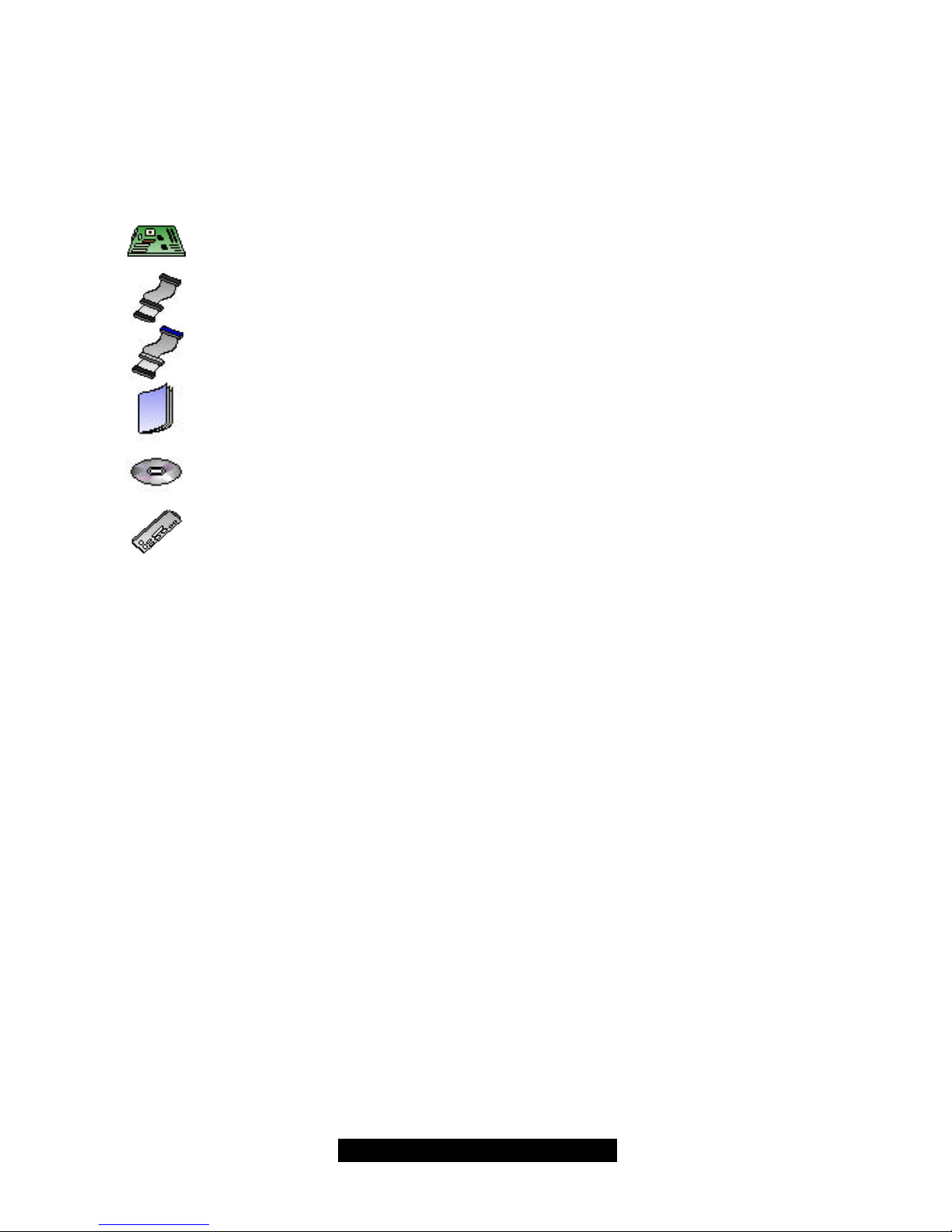
The retail motherboard package should contain the following:
1x Tomcat i815ef motherboard
1x 34-Pin floppy drive cable
1x Ultra-DMA-100/66/33 IDE cable
1x Tomcat i815ef user’s manual
1x TYAN driver CD
1x I/O shield plate with dual LAN ports
If any of these items are missing, please contact your vendor/dealer for replacement before
continuing with the installation process.

4
http://www.tyan.com
Chapter 1: Introduction
1.1 Congratulations!
You are now the owner of the TYAN Tomcat i815ef motherboard. The TYAN Tomcat i815ef
provides leading edge features and performance for systems based on the Flex ATX form factor.
Utilizing the Intel 815e (B-Step) chipset, this system board supports Intel’s Celeron, Pentium III as
In addition to flexible processor support, the Tomcat i815ef features dual LAN ports, perfect for
supporting simultaneous connections to a network and a broadband communications device. This
platform also features two DIMM sockets, two PCI slots, dual-channel UltraDMA-100, USB and
more! *Please see TYAN’s website for updates and information concerning CPU information and
support:
http://www.TYAN.com
While the Tomcat i815ef is designed to fit into tight quarters, it also offers expansion options via
two PCI slots. However, with all critical devices and tool built onboard already, the Tomcat i815ef
cuts down on costs as well as time.
Remember to visit TYAN’s Website at http://www.tyan.com. There you can find information on all
of TYAN’s products with FAQs, distributors list and BIOS setting explanations.
1.2 Hardware Specifications
Processor
• Single PGA370 ZIF sockets
• Supports one Intel Celeron or Pentium III
processor, including the new Tualatin CPU
• SDR bus support for 133MHz
• Integrated VRM (VRM 8.5 spec)
Chipset
• Intel i815e (B-Step) Chipset
• National PC87366 Super I/O ASIC
Memory
• Two 3.3v 168-pin DIMM sockets
• Supports up to 512MB of unbuffered PC133
SDRAM (only)
Expansion Slots
• 2 32-bit/33MHz PCI bus mastered slots (5V)
Integrated PCI IDE
• Two 40-pin IDE connectors for up to 4
devices
• PIO mode 3, 4, UltraDMA 33/66/100 support
• ATAPI, HDD, CDROM device support
Integrated LAN
• Two Intel 10/100 LAN controllers (per
controller)
• One via 82599 controller and one via Intel’s
ICH2 (8252EM)
Integrated 2D/3D Graphics
• Onboard Intel 815e graphics accelerator
• Standard 15-pin analog VGA out
BIOS
• AMI 4Mb BIOS Flash ROM
• Fully Plug-and-Play
• APM 1.2/ACPI 1.0/PC99 compliant
• DMI 2.0 compliant
• Soft Power Down
• Multiple boot options
Form Factor
• Flex ATX footprint (9” x7.5”
228.6mmx190.5mm)
• One 20-pin ATX power connector
• Stacked USB (two) ports
• Stacked keyboard and mouse ports

5
http://www.tyan.com
Integrated I/O
• One floppy connector supports up to two
drives
• Two 9-pin 16550-based serial ports
• One 25-pin SPP/ECP/EPP parallel port
• One IR Tx/Rx header
• 2 USB ports (additional via optional cable)
• PS/2 keyboard and mouse ports
Regulatory
• FCC DoC (declaration of Conformity)
• European Community of CE (declaration of
Conformity)
1.3 Software Specifications
OS Windows 9x/ME/NT/2000

6
http://www.tyan.com
Chapter 2: Board Installation
Installation
You are now ready to install your motherboard. The mounting hole pattern of the Tomcat i815ef
matches the ATX system board specifications. Your chassis should support a standard ATX
motherboard form factor.
How to install our products right… the first time
The first thing you should do is read this user’s manual. It contains important information which will
make configuration and setup much easier. Here are some precautions you should take when
installing your motherboard:
(1) Ground yourself properly before removing your motherboard from the antistatic bag.
Unplug the power from your computer power supply and then touch the power supply.
For the safest conditions, Tyan recommends wearing a static safety wrist strap.
(2) Hold the motherboard by its edges and do not touch the bottom of the board.
(3) Avoid touching the motherboard components, IC chips, connectors, and leads.
(4) Avoid touching memory module contacts and IC chips
(5) Place the motherboard on a grounded antistatic surface or on the antistatic bag from
which it came in.
Having reviewed the precautions above, the next step is to take the motherboard out of the
cardboard box and static bag, hold it by its edges and place it on a grounded antistatic surface,
component side up. Inspect the board for damage.
NOTE DO NOT APPLY POWER TO THE BOARD IF IT HAS BEEN DAMAGED
7
http://www.tyan.com
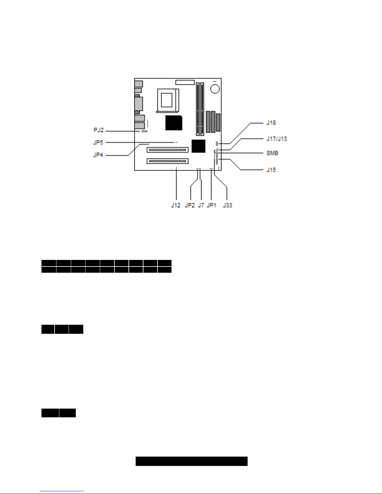
2.1 – Jumper Section
Pin outs for certain connectors are available on the Tyan website: http://www.tyan.com
2.1a Front Panel Connector (J15)
Your chassis will usually come with connectors to install onto the motherboard, such as HDD and
Power LEDs. The Front Panel Connector (J80) has been implemented for such purposes.
17 15 13 11 9 7 5 3 1
18 16 14 12 10 8 6 4 2
1,3: HD LED
2,4: Power LED
5,7: Reset Switch
6,8: Power Switch
11-17: Infra Red (IR) On/Off
2.6b – CMOS Reset (JP1)
1 2 3
1,2: Connect these two pins together to reset the CMOS settings in case an
incorrect setting causes system instability or you have forgotten your system/setup
password of have just flashed your BIOS.
- Power off the system and disconnect the power supply.
- Close pins 2 and 3 on JP1
- Wait about 5 seconds
- Close pins 1 and 2 on JP1
- Reconnect the power supply and power on the system
2.6c – Disable/Enable LAN1 (JP5)
1 2
Closed (default): LAN1 port is disabled.
Open: LAN1 port is enabled.

8
http://www.tyan.com
2.6d – Disable/Enable LAN2 (JP4)
1
2
Closed (default): LAN1 port is disabled.
Open: LAN1 port is enabled.
2.6e – Hard drive activity LED (J12)
1
2
Use this jumper to connect your chassis’ hard drive LED.
2.6f – Flash Open (JP2)
1 2
Closed (default): Allows you to upgrade the onboard CMOS
Open: Prevents onboard CMOS from being upgraded
2.6g – COM2 connector (PJ2)
This connector allows you to use the supplied serial extension cable if you need to use more than
1 serial devices.
2.6h – Chassis Intrusion header (J7) [optional]
1 2
Use these connectors if your chassis has intrusion detection, otherwise, leave it as is.
2.6i–USB connector (J18)
This connector allows you to use your chassis’ front panel USB connector if it comes with one.
1
2
3
4
If 3 and 4 are connected (default), the motherboard will use the onboard speaker for
audio related purposes. If 3 and 4 are not connected, you may use you chassis’
internal speaker. Either one will be fine.
2.6k –ACPI LED (J33)
1
2
3
Use this connector if your chassis has front LEDs for notification for sleep or suspend
modes.
9
http://www.tyan.com
2.7 Mounting the motherboard
Your chassis may include mounting hardware. If mounting hardware was included, you can use
the following examples to help you in stalling your motherboard into the chassis.
If your chassis has the studs integrated into the chasses wall, then you would only need to use
screws (possibly included with your chassis) to install the motherboard. See examples (Figure 2.0,
shown below for more details.
If the chassis includes mounting hardware without the studs pre-installed, then you will need to
install the motherboard using the mounting hardware as shown in the examples below.
Remember not to over tighten any of the screws, or you may risk breaking internal traces in the
surrounding area, or damage the motherboard in some other way.
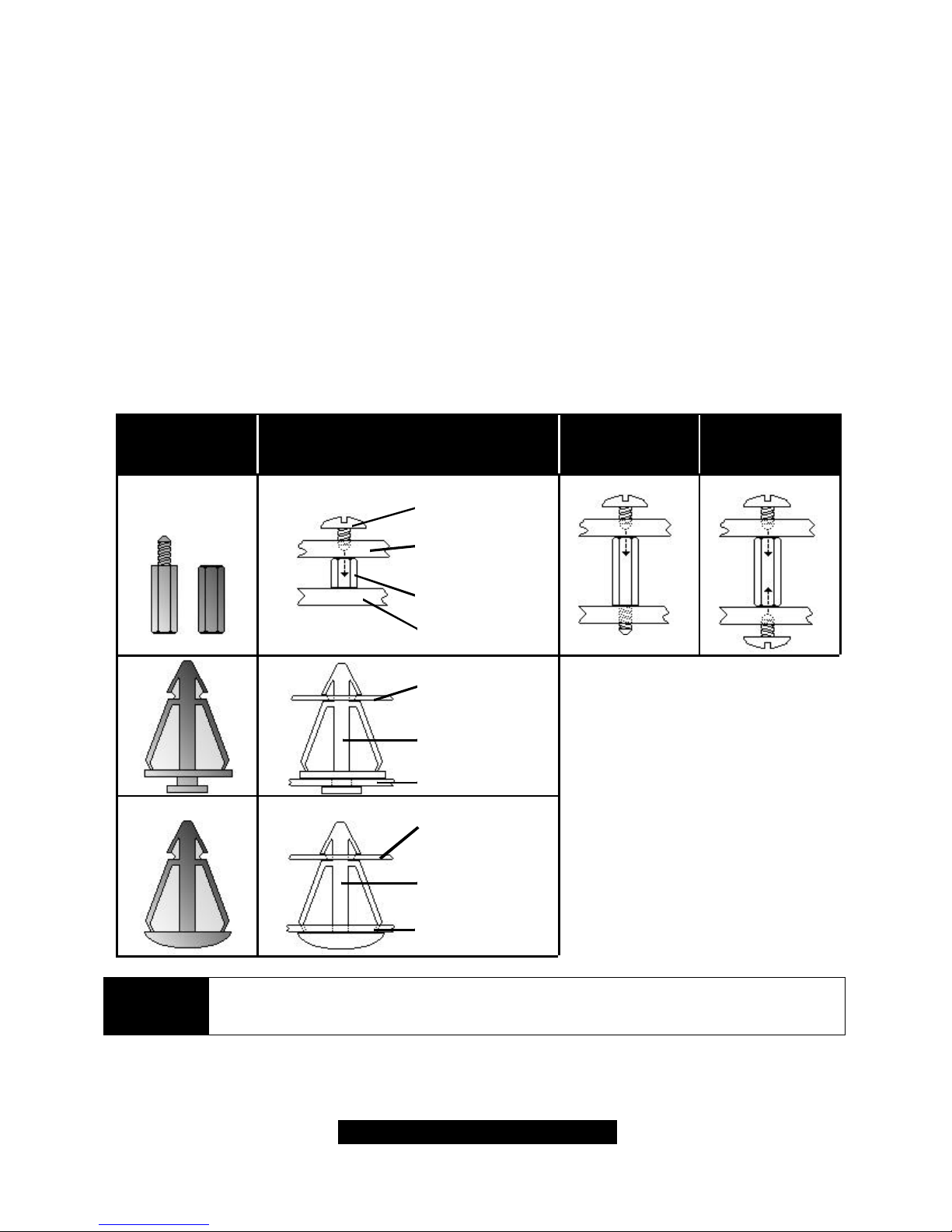
Other examples of how to install your motherboard using other hardware (that may or may not
have been included with your chassis) are shown below.
One solution for installing motherboardType of hardware Another solution
NOTE
The diagrams above are only representative of a few solutions for installing a
motherboard into the chassis. The installation procedure for installing your
motherboard into the chassis may differ.

10
http://www.tyan.com
2.8 Installing Memory
Please keep in mind that although some memory modules may appear to be high-quality, they
may contain inferior or substandard parts. The type of memory you choose to install should be
checked against the memory compatibility list, which is available from Tyan’s website at
http://www.tyan.com.
Here are some details of memory installation for this board:
- At least one SDRAM DIMM must be installed for the system to POST.
- Supports 128MB, 256MB, and 512MB PC133/100 SDRAM.
- All installed memory will be automatically detected.
- The motherboard supports up to 512MB of PC133 unregistered/unbuffered SDRAM
memory.
Memory Installation Procedure
Step1: Line your module up so that the pins fit into the socket. There is only one way your DIMM
can fit properly. Make sure that the short row of pins is lined up with the short gap in the DIMM
socket, just as the long row of pins should line up with the long gap in the DIMM socket.
Step2: Insert the DIMM by pushing the module into the socket with even force Do not insert one
end and then the other: install the whole module at once or you might bend the DIMM pins. Make
sure the DIMM is securely seated.
NOTE
Your memory modules may not look like those in the above diagram; they are
used simply as examples.
Look the DIMM into place by pushing the clips back on either end of the socket onto the notches
in the ends of the DIMM (see pictures above details).
11
http://www.tyan.com
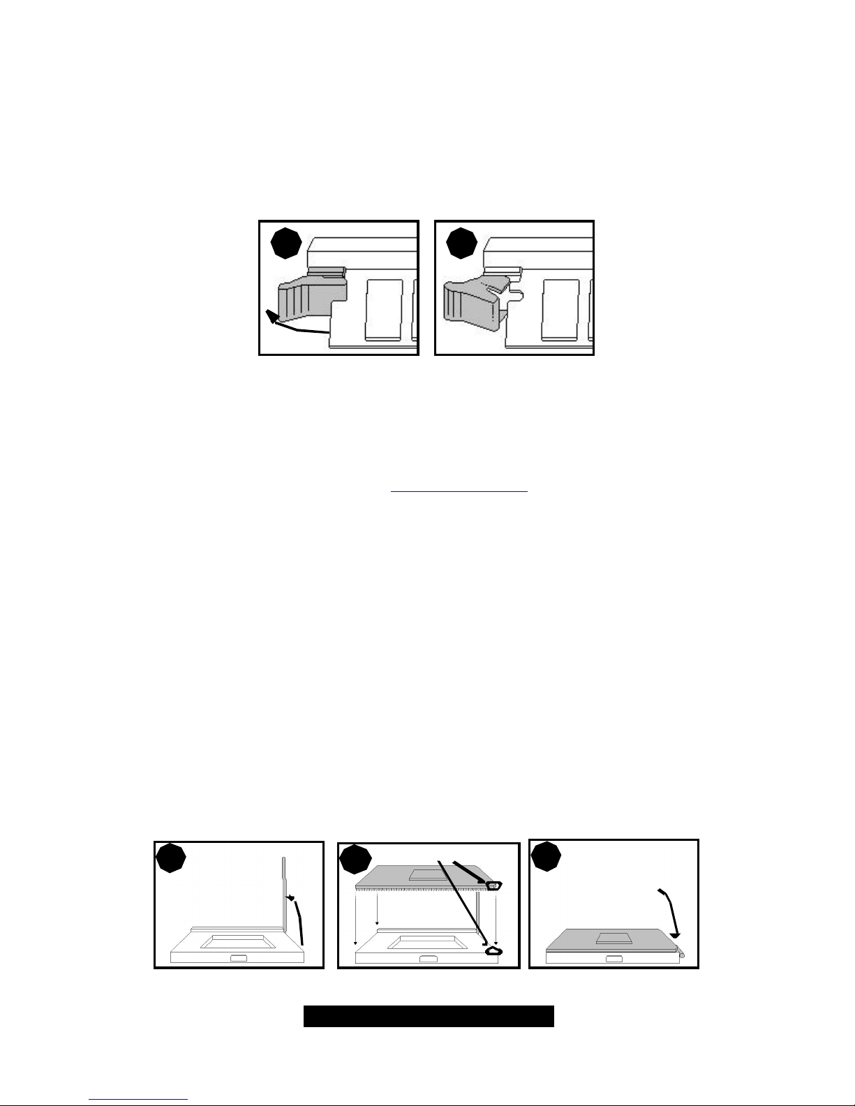
Removing a DIMM
Removing a DIMM is just the reverse: pull back the clips from the DIMM (see pictures on previous
page), and carefully pull the module straight out. Place the DIMMs in an anti-static bag as soon as
you remove them to avoid static damage.
1 2
2.9 Installing the CPU and Cooling Fan
Intel Pentium III processors up to 1.13GHz can be used on this board. For more information on
CPU compatibility, check Tyan’s website at http://www.tyan.com/
When installing your CPU, remember the following:
- The CPU is a sensitive electronic component and can easily be damaged by static
electricity
- Do not touch the CPU pins with your fingers
- You should be able to insert the CPU into the socket with virtually no force
- Do not press down hard on the CPU as you might bend or break pins, or otherwise
damage the CPU.
- The CPU voltage will automatically be detected by the motherboard, so there is not
need to set any jumpers or BIOS setting.
Installing the CPU
Before installing the CPU, check it for any visible damage. Make sure none of the pins are bent or
missing. Be sure where Pin 1 is on both the CPU and the socket. The following steps each have
corresponding picture next to it to help guide you through the installation.
Careful lift the arm of the ZIF socket until it is at 90 degree angle pointing away from the
motherboard. Be very careful not to damage any components that might be next the socket.
1
2
3
12
http://www.tyan.com
There are two beveled corners on the CPU, which will match the two angled corners on the
socket. Careful install the CPU by lining both Pin 1 on the CPU and Pin 1 on the socket, making
sure the pins actually fit into the socket. Do not force the CPU into the socket: check the pin
alignment of the CPU pins to socket holes.
Push down lightly on the CPU while lowering the arm on the socket to secure the CPU (see right).
A squeaking noise may be heard while lowering the arm or the socket may make a ‘click’ noise
when the arm is locked into position: these noises are normal.
Installing the Cooling Fans
After a CPU has been installed, you will need to install the proper cooling device for the CPU. This
device, a heatsink/fan combination can be purchased at many computer retail stores. Installation
of the cooling device may vary depending on the fan manufacturer’s design. You should also take
space into consideration when installing a cooling device: make sure the cooling device is not too
big, or else you may end up damaging components around the CPU socket.
Tyan highly recommends that you use a thin
layer of some type of thermal compound
(available from many computer retail stores),
between the CPU and the heatsink, to
maximize distribution of heat away from the
CPU. Please use extra caution when installing
any type of clamp-style fan, or else damage
may occur to the CPU socket and or the CPU
itself.
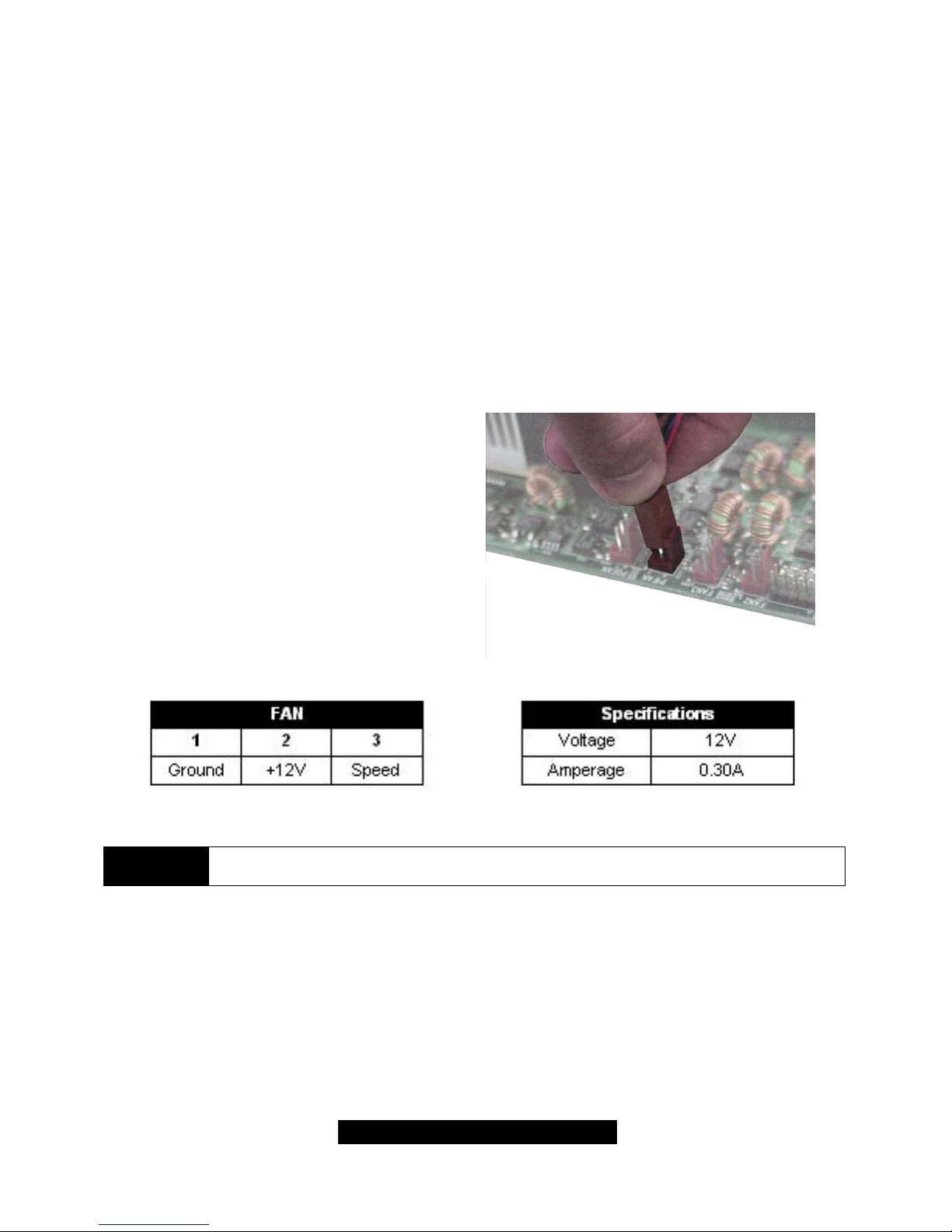
NOTE
The FAN connector has a 12V, 0.30A limitation. Tyan takes no responsibility and
will not be held liable for damage related to the misuse of any FAN jumper.
Alternatively, if you wish to also install chassis fans for increased cooling, headers are provided to
power those fans as well. Chassis fan installation will vary depending on your chassis
manufacturer’s design. Please check with your chassis manufacturer for details on proper chassis
fan installation.
13
http://www.tyan.com
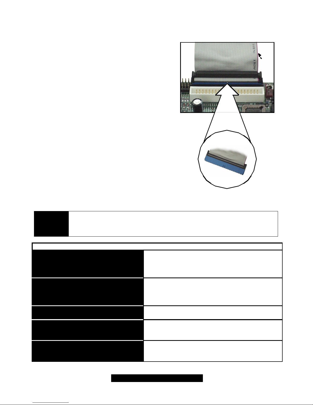
2.10 Connecting IDE and Floppy Drives
A variety of IDE and ATAPI-compliant devices can be
installed on this motherboard, such as hard disk drives
(HDDs) and CD-ROMs.
Please keep in mind that on this motherboard, the
primary IDE connector is BLACK, and the secondary
IDE connector is WHITE. See the picture to the rightfor
an example of the IDE cable properly connected to the
motherboard, with the BLUE end of the IDE cable
installed on the motherboard.
Pin 1 on the IDE cable is usually denoted by a red or
colored stripe down one side of the cable. That side of
the cable must match Pin 1 on the motherboard’s IDE
connector. There will also be a key pin on the cable that
matches with a notch in the IDE connector, to ensure
proper installation. Consult the documentation that
came with your IDE/ATAPI device, or contact the
device’s manufacturer for more details on installation.
Please note that UltraDMA-100/66 IDE HDDs require a
special 80-wire cable (see picture at right), which has
additional grounding wires. This cable has been
included with this motherboard for your convenience.
The UltraDMA-100/66 cable is backwards compatible
with UltraDMA-33 and legacy IDE HDDs.
BLUE end goes to IDE connector
Pin 1
NOTE
Only Tyan-approved cables are recommended for this motherboard. If you are
using an existing configuration with older cables, your system might not function
properly. Use only Tyan-approved cables (i.e. the ones included with your new
motherboard).
Some symptoms of incorrectly installed HDDs are...
May be a Master/Slave configuration problem, bad
IDE cable, or BIOS mis-configuration. Consult the
HDD documentation or contact your HDD vendor.
May be a bad cable or lack of power going to the
drive. Check the cables for damage and bad connections.
Usually means the cable was installed backwards.
Bad IDE cable or defective drives/motherboard. Try
another HDD, or contact your HDD vendor.
Check power cables and cabling. May be a bad
power supply or IDE drive problem.
HDD lights are constantly on
HDDs are not auto-detected
No video or beeps during bootup
HDD does not power on
Hard Disk Drive Fail message at bootup
14
http://www.tyan.com
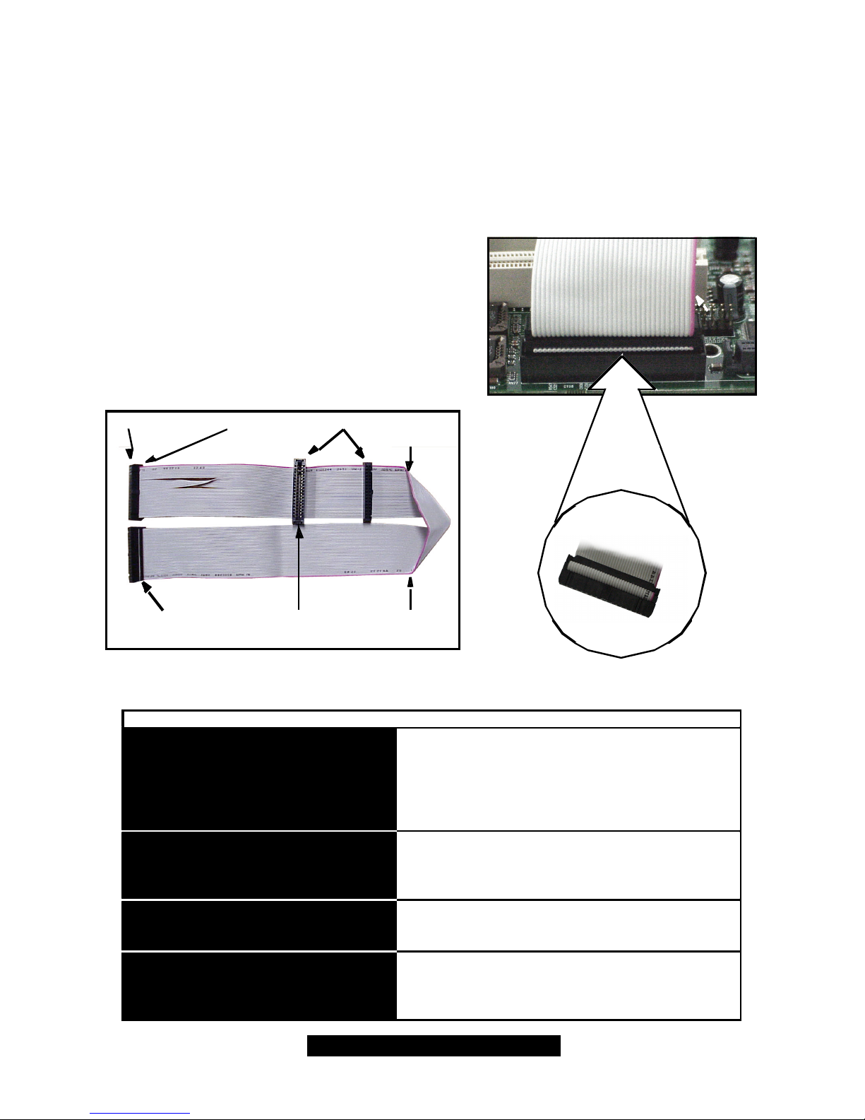
Connecting Floppy Drives
See the picture below for an example of a floppy cable. Most of the current floppy drives on the
market require that the cable be installed with the colored stripe positioned next to the power
connector. In most cases, there will be a key pin on the cable which will force a proper connection
of the cable.
The first floppy drive (sometimes denoted as A:) is
usually attached to the end of the cable with the twist
in it. Drive B: is usually connected to the second or
third connector in the cable (the second or third
connector after you install Drive A:). Refer to your
floppy drive’s installation instructions (if available), or
contact your dealer if you are unsure about how to
attach the floppy drive(s). Remember, you can only
have 2 floppy drives connected at any given time.
Figure 2.
4*
3.5” connector
5.25” connector Colored stripe
indicates Pin 1
Drive B:Drive A: Colored stripe
indicates Pin 1
Match striped side with Pin 1
Usually caused by faulty cables, cables put in backwards, or a bad floppy or motherboard. Try another
floppy drive to verify the problem or try another
cable. Also check to see if the onboard floppy is
enabled in the BIOS.
The cable, floppy, or motherboard may be faulty. Try
another cable or floppy drive to verify.
Usually signifies that the cable is on backwards.
Reverse the cable at the floppy drive end and try
again.
Check power cables and cabling. May be a bad
power supply or IDE drive problem.
FDD light is constantly on
FDDs are not auto-detected
FDD does not power on
Floppy Drive Fail message at bootup
Some symptoms of incorrectly installed FDDs are...
 Loading...