

TYAN S2420 User Manual

Tyan S2420
Tomcat i810ef
Motherboard Users Manual
Revision 1.20
Copyright © Tyan Computer Corporation, 2000. All rights reserved. No part of this
manual may be reproduced or translated without prior written consent from Tyan
Computer Corp.
All registered and unregistered trademarks and company names contained in this
manual are property of their respective companies including, but not limited to the
following.
AMI is a trademark of American Megatrend Incorporated
Windows is a trademark of Microsoft Corporation.
IBM, PC, AT, PS/2 are trademarks of IBM Corporation.
INTEL, Pentium II/III, Celeron are trademarks of Intel Corporation.
Tomcat i810ef S2420 is a trademark of Tyan Computer Corporation.
Information contained in this publication has been carefully checked for accuracy and
reliability. In no event will Tyan Computer be held liable for any direct or indirect,
incidental or consequential damage, loss of use, loss of data, or other malady resulting
from errors or inaccuracies of information contained in this manual. The information
contained in this document is subject to change without notice.
PRINTED IN USA

Table of Contents
1. Introduction................................................................................................. 4
Overview........................................................................................... 4
Icons................................................................................................. 5
Hardware Specifications/Features................................................ 6
Software Specifications.................................................................. 7
Technical Support........................................................................... 8
Returning Merchandise for Service............................................. 8
2. Board Installation..................................................................................... 10
Unpacking....................................................................................... 10
Installation...................................................................................... 10
Quick Reference for Jumpers........................................................ 12
Map of Motherboard Jumpers..................................................... 13
Setting Jumpers............................................................................... 15
Chassis Intrusion Alarm Connector............................................ 15
Flash EEPROM............................................................................... 16
Boot Block Jumper.......................................................................... 16
Clear CMOS & Reset Password .................................................. 16
Soft Power Connector.................................................................... 18
Hardware Reset Switch Connector Installation......................... 18
CMOS RTC...................................................................................... 18
Mounting the Motherboard in the Chassis .............................. 19
Installing Memory.......................................................................... 19
Installing the CPU and Cooling Fan........................................... 22
Connecting IDE and Floppy Drives............................................ 23
Installing Add on Cards ............................................................... 25
Connecting PS/2, USB, Serial and Parallel Devices.................. 26
Connecting the Power Supply...................................................... 27
Frequently Asked Questions....................................................... 28
3. BIOS Configuration................................................................................. 30
Main Setup Menu.......................................................................... 31
Advanced CMOS Setup............................................................... 36
Advanced Chipset Setup.............................................................. 41
Power Management Setup............................................................ 46
Plug and Play Setup....................................................................... 51
Peripheral Setup.............................................................................. 55
Supervisor and User Password.................................................... 59
Flash Writer Utility......................................................................... 60

4. System Resources.................................................................................... 62
Beep Codes..................................................................................... 62
Troubleshooting System Problems............................................. 63
Displayed Error Messages.......................................................... 64
Appendix - Glossary....................................................................................... 66
http://www.tyan.com
4
Chapter 1
Introduction
Overview
The Tomcat i810ef is a quality, high performance motherboard designed for
Socket 370 Intel Celeron / Pentium III microprocessors. The Tomcat i810ef
utilizes the Intel i810ef Chipset with AMI BIOS and can support Celeron /
Pentium III CPU speeds of 300MHz through 800+ MHz, and host bus speeds
of 66MHz to 133MHz. For CPU speed support, please refer to the CPU
Compatibility Chart on Tyans website:
http://www.tyan.com/support/html/pentiumii_iii_ppga.html
The Tomcat i810ef motherboard provides high performance capabilities that
are ideal for a wide range of demanding applications such as CAD, CAM,
CAE, desktop publishing, 3D animation, and video production.
This integrated high-performance system board in a Flex-ATX form factor
offers more features and expandability than other Flex-ATX boards in its class.
Some of the features included are onboard UltraDMA / 66, 133 MHz Front Side
BUS Speed, onboard digital link sound with AC97 Codec, onboard VGA port,
built-in Intel 3D Graphics accelerator and onboard 4MB 133 MHz display
cache for enhanced graphics performance.
chapter 1
Introduction
S2420 Tomcat i810ef
5
INTRO
Flexibility and high-integration have been designed into the Tomcat i810ef.
With I/O and drive controller support built onboard (along with the many
onboard features previously mentioned), the two PCI slots are free for more
add-on expansion cards. Remember to visit Tyans Website at www.tyan.com,
there you can find information on all of Tyans products along with FAQs,
distributors list, drivers, and BIOS setting explanations.
Icons
In order to help you navigate this manual and set up your system, we have
added several icons to our format.
This icon alerts you to particularly important details regarding the
setup or maintenance of your system. This icon often appears next to
information that may keep you from damaging your board or system.
While we will often point out the most vital paragraphs in a chapter,
you should always read every word in the text. Failing to do so can
lead to exasperation and expense.
Wherever possible, we have included step-by-step instructions for
setting up your system, which are indicated by this icon. However, it
is in your best interest to read an entire section (and perhaps the
entire manual) before you begin to fiddle with your motherboard.
While we have alerted you to potential dangers in several places in
the manual with this icon, these warnings should not be regarded as
the whole of your safety regimen. Never forget that computers are
electrical devices, and are capable of delivering a shock. Prevent
damage to yourself and to your board: always ensure that your
system is turned off and unplugged whenever you are working with
it, and that you are equipped with a static safety device.
procedure
1.
2.
3.
!
important!
warning

http://www.tyan.com
6
Chapter 1
Introduction
Hardware Specifications/Features
Processor Information Socket 370 Type CPU**
66/100/133MHz bus support**
Celeron/III processor up to 800+ MHz**
Integrated VRM 8.4
Chipset Information Intel 810e AGPset
GMCH (82810e), ICH (82801AA), 4Mb FWH
ITE 8712F (or 8702F) LPC Super I/O Chipset
BIOS Information AMI Plug and Play flash BIOS
ACPI & APM/ Year 2K
Bicolor LED for PC99 compliance
Soft power-down
Win98 Ready / DMI 2.0 compliant
Main Memory Max. 512MB support
Two 3.3V 168-pin DIMM sockets
PC100 SDRAM support only
Expansion Slots Two 32-bit PCI 2.2 Bus Master slots
EXTSMI Server Management Connector
Disk Drive & System I/O UltraDMA/66 support (up to 4 drives)
Two 40-pin EIDE connectors (Primary/
Secondary)
Two floppy drives (up to 1.44MB / Mode 3)
Two 9-pin 16550 UART Serial ports
One 25-pin ECP/EPP Parallel port
Two USB rev 1.2 ports
PS/2 Mouse & Keyboard ports
Chassis Intrusion Alarm Header
One 20-pin Server Management Connector
3D Graphics Accelerator Intel graphics engine integrated in chipset
Standard 15-pin Analog VGA port
Digital video-out 20-pin header for LCD
monitor (optional)
4MB 133 MHz display cache onboard for
enhanced graphics performance

S2420 Tomcat i810ef
7
AC97 Sound Digital link sound with AC97 Codec onboard
One Game port
Audio line-in, microphone, and speaker ports
Network Feature Intel 82559 10/100 Ethernet onboard
3-pin Wake on LAN Header
3-pin Wake on Ring Header
(requires ATX 2.01 power supply)
Voltage and Power ATX power supply connector
Information +12V power source for DC fan onboard
3.3V unbuffered PC100 SDRAM
Power recovery after interrupt feature
Utilizes GTL+ bus to reduce power
consumption and EMI
Physical Dimensions Flex-ATX design
9.0 x 7.5
** See Tyan website at www.tyan.com for CPU Compatibility List.
Software Specifications
OS Operates with Windows 98, Windows 2000,
Windows NT 4.0, and SCO UNIX.
INSTALL

http://www.tyan.com
8
Chapter 1
Introduction
Technical Support
If a problem arises with your system, you should turn to your dealer for help
first. Your system has most likely been configured by them, and they should
have the best idea of what hardware and software your system contains.
Hence, they should be of the most assistance. Further, if you purchased your
system from a dealer near you, you can actually bring your system in to them
to have it serviced, instead of attempting to do so yourself (which can have
expensive consequences).
Help resources:
1. See FAQ and beep codes sections of this manual.
2. See Tyan web site for FAQ, bulletins, driver updates, etc.
http://www.tyan.com
3. Contact your dealer or distributor for help BEFORE calling Tyan.
4. Check the Tyan user group: alt.comp.periphs.mainboard.tyan
Returning Merchandise for Service
During the warranty period, contact your distributor or system vendor FIRST
for any product problems. This warranty only covers normal customer use and
does not cover damages incurred during shipping or failure due to the
alteration, misuse, abuse, or improper maintenance of products.
For Resellers Only:
A receipt or copy of your invoice marked with the date of purchase is required
before any warranty service can be rendered. You can obtain service by calling
the manufacturer for a Return Merchandise Authorization (RMA) number. The
RMA number should be prominently displayed on the outside of the shipping
carton and the package should be mailed prepaid, or hand-carried to the
manufacturer. Tyan will pay to have the board shipped back to you.

S2420 Tomcat i810ef
9
INTRO
This page left blank intentionally.
http://www.tyan.com
10
Chapter 2
Board Installation
chapter 2
Board Installation
Unpacking
The motherboard package should contain the following:
(1) Tomcat i810ef S2420 mainboard
(1) 40-pin IDE and 34-pin floppy cable pack
(1) 80-pin ATA-66 IDE cable included
(1) Tomcat i810ef S2420 Users Manual
(1) Driver CD
(1) I/O shield (optional) included if purchasing Tomcat i810ef S2420 with LAN
option
Installation
You are now ready to install your motherboard. The mounting hole pattern of
the Tomcat i810ef S2420 matches the Flex-ATX system board specifications.
Your chassis should support a Flex-ATX mainboard form factor.
How to install our products right... the first time.
Whats the first thing I should do?
The first thing you should do is read this users manual. It contains important
information which will make configuration and setup much easier.
S2420 Tomcat i810ef
11
procedure
1.
2.
3.
INSTALL
Here are some precautions you should follow when installing your motherboard:
(1) Ground yourself properly before removing your motherboard
from the antistatic bag. Unplug the power from your computer
and then touch any metal part on the computer case. (Or wear a
grounded wrist strap.)
(2) Hold the motherboard by its edges and do not touch the bottom of
the board.
(3) Avoid touching motherboard components, IC chips, connectors,
and leads.
(4) Avoid touching pins of memory modules and chips.
(5) Place motherboard on a grounded antistatic surface or on the
antistatic bag.
Having reviewed the precautions above, the next step is to take the motherboard out of the cardboard box and static bag, hold it by its edges, and place it
on a grounded antistatic surface, component side up. Inspect the board for
damage.
DO NOT APPLY POWER TO THE BOARD IF IT HAS BEEN DAMAGED!
Press down on any of the socket ICs if it appears that they are not properly
seated (the board should still be on an antistatic mat). Do not touch the bottom
of the board. Remember, dont take any electronic device out of its protective
bag until you are ready to actually install it into the computer case. If you do
not ground yourself, you risk zapping the motherboard or adapter card.
Subsequent problems may not arise immediately because electrostatic discharge damage, unlike physical damage, causes the device to fail over time.
Installation Steps
1. Set Jumpers
2. Mount Motherboard in Chassis
3. Install Memory
4. Install CPU & Cooling Fan
5. Connect IDE and Floppy Drives
6. Install Add-on Cards
7. Connect PS/2, USB, Serial and Parallel Devices
8. Connect Power Supply
!
important!
http://www.tyan.com
12
Chapter 2
Board Installation
Quick References for Jumpers
In this manual, the terms closed and on are used when referring to jumpers
(or jumper pins) that are active; open and off are used when referring to
jumpers (or jumper pins) that are inactive. See the Figure 2-1 for examples of
on and off pins and jumpers. The square pin in the diagram is Pin 1.
Jumpers and pins are connected by slipping the blue plastic jumper connector
overtop of two adjacent jumper pins (indicated by 1-2 or 2-3). The metal rod
inside the plastic shell bridges the gap between the two pins, completing the
circuit. See Figure 2-2 for more example of pin connections.
Figure 2-1 Figure 2-2
The tables and maps on the following pages will help you set the jumpers for
CPU speed, Infrared, and external connector pin assignments, among others.
The miniature motherboard maps will help you locate the jumpers on your board.
A full-page map of the motherboard can be found on the next two pages.
2 pin jumpers
off on
3 (or more) pin jumpers
1-2 2-3 open
1
2
3
1
2
3
1
2
3
S2420 Tomcat i810ef
13
INSTALL
The tiny 1s next to jumpers of 3 pins or more indicate the position of pin 1
for that jumper.
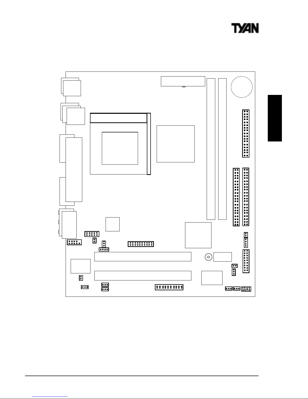
Map of Motherboard Jumpers
USB0
Keyboard
Mouse
DIMM bank 1
DIMM bank 0
VGA
COM1
Printer Port
PCI slot 2
PCI slot 1
Intel 810e
Chipset
Intel
82801AA
ATX power connector
Joystick
Line in
Microphone in Line out
Primary IDE connector
Secondary IDE connector
1
1
Floppy drive connector
1
3 volt
lithium
battery
JP2
J14
J44
J32 (CD)
1
J43
J1
J9
J15
J38
J25 (COM2)
AMIBIOS
J36 (DFP Connector)
Socket 370
CPU
PGA370
Int. SPKR
CLR CMOS
WOR(J28)
WOL (J2)
CPU FAN
CHS FAN (J11)
Intel
559
JP3
JP4
1
1
Super I/O
Riser Card
1
J45
1
Ethernet
SCSI LED
USBLED
J12
JP6
Server Management
1
USB1
http://www.tyan.com
14
Chapter 2
Board Installation
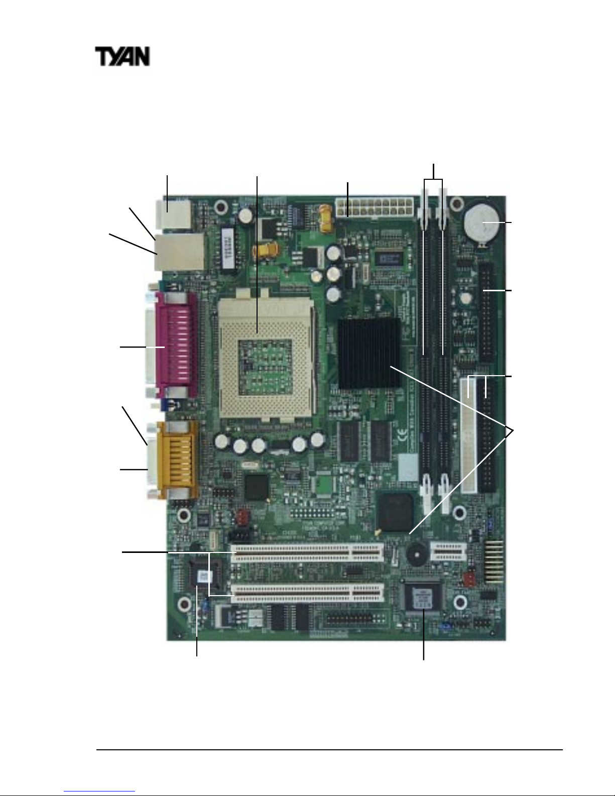
2 DIMM slots
PS/2 Mouse &
Keyboard
ports
Floppy port
ATX power
supply header
2 PCI slots
Battery
2 USB ports
1 Parallel, 1 Com,
1 VGA ports
2-ch EIDE
Intel 810e AGPset
AMI
(BIOS)
Audio ports
Joystick
Map of S2420 Features
Socket 370 for
Celeron/PentiumIII CPU
Ethernet(optional)
Super I/O
S2420 Tomcat i810ef
15
INSTALL
1. Setting Jumpers
Note: There are no Jumper settings for CPU bus speed or clock multiplier on
the S2420 board. The Tomcat i810ef is designed to automatically detect the
socketed CPU and its proper speed settings.
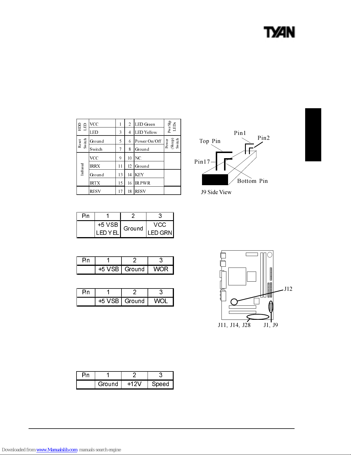
1-A. J9 External Pin Assignments
1-B. Power LED (J14)
Jumper J14 is a 3-pin ACPI LED
header. If you need a 2-pin Power
LED header, use jumper J9 above.
1-C. Wake-On Ring Connector -optional (J28)
1-D. Wake-On LAN Connector -optional (J2)
1-E. Chassis Intrusion Alarm Connector (J1)
The J1 connector is an intrusion alarm, that can be
connected to the system chassis. When active (J1
is connected to the chassis), this alarm will alert the system administrator
anytime someone opens the systems case.
1-F. CPU Fan (J12) / Chassis Fan Connector (J11)
CPU Fan connector is for the CPU fan. CHS Fan1connector is for the Chassis
Fan. You may monitor the status of these Fans when using Intels LANDesk
system management software.
9&& /('*UHHQ
/(' /('<HOOR Z
*URXQG 3RZHU2Q2II
6ZLWFK *URXQG
9&& 1&
,55; *URXQG
*URXQG .(<
,57; ,53: 5
5(69 5(69
+
'
'
/
(
'
5
H
V
H
W
6
Z
L
W
F
K
,
Q
I
U
D
U
H
G
3
Z
U
6
O
S
/
(
'
V
3
R
Z
H
U
6
O
H
H
S
6
Z
L
W
F
K
Top Pin
Bottom Pin
J9 Side View
Pin1
Pin17
Pin2
3LQ
96% *URXQG : 2 5
3LQ
96% *URXQG : 2 /
3LQ
*URXQG 9 6SHHG
3LQ
96%
/( '<(/
*URXQG
9&&
/( '*5 1
J11, J14, J28
J12
J1, J9
http://www.tyan.com
16
Flash EEPROM
The Tomcat i810ef uses flash memory to store BIOS firmware. It can be
updated as new versions of the BIOS become available. You can upgrade your
BIOS easily using the flash utility. In order to flash the BIOS, do the following:
i. Shutdown the system, and close jumper JP3 to disable the boot
block protection (see Boot Block section below). Then boot
system to DOS.
ii. Type flash4mb followed by <ENTER> key.
iii. Choose whether to save or not save the old BIOS.
iv. Type in the BIOS filename, like BIOSFILE.ROM.
v. Flash utility will auto-complete the flash, including updating the
boot block at this point.
vi. Shutdown the system, and open jumper JP3 again.
Remember to clear the CMOS (see CMOS section below)
before turning your system back on.
See page 60 for more details about the Flash Writer Utility.
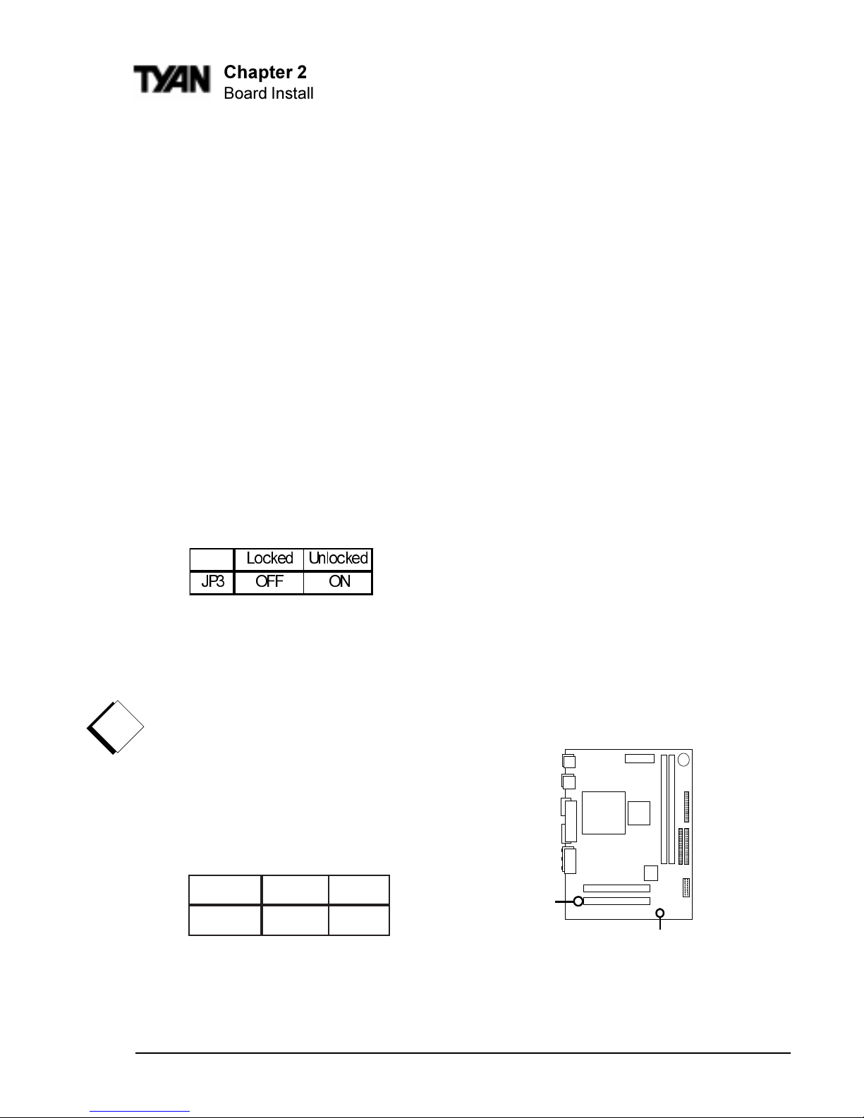
1-G. Boot Block Jumper (JP3)
By default, this jumper is set to the OFF (locked) position. Having the Boot
Block protection locked will allow system-bootup even if the BIOS bootup
fails. In other words, the boot block acts as a backup in case your BIOS fails
to boot the system. If the jumper is set to the ON position, this would allow
the Boot Block to refresh its BIOS code at the same time you flash a new BIOS.
Note: If the Boot Block is unlocked (jumper ON)
and if failure occurs during a new BIOS Flash,
you run the risk of rendering your entire system
un-bootable. The backup protection of the Boot
Block will be lost.
1-H. Clear CMOS and Reset Password (JP2)
If you have been locked out of your system
because you forgot your password or set the CMOS incorrectly, follow the
instructions on the next page.
/RFNHG 8QORFNHG
-3 2)) 21
Chapter 2
Board Installation
tluafeDteseR
2PJ
2-13-2
!
important!
JP2
JP3
S2420 Tomcat i810ef
17
1. Power off the system
2. Set jumper JP2 to pins 2 and 3
3. Wait for 10 seconds, then return jumper JP2 to pins 1 and 2.
4. Power on the system again.
By following this procedure, you will erase your password and reset the
CMOS to the BIOS defaults.
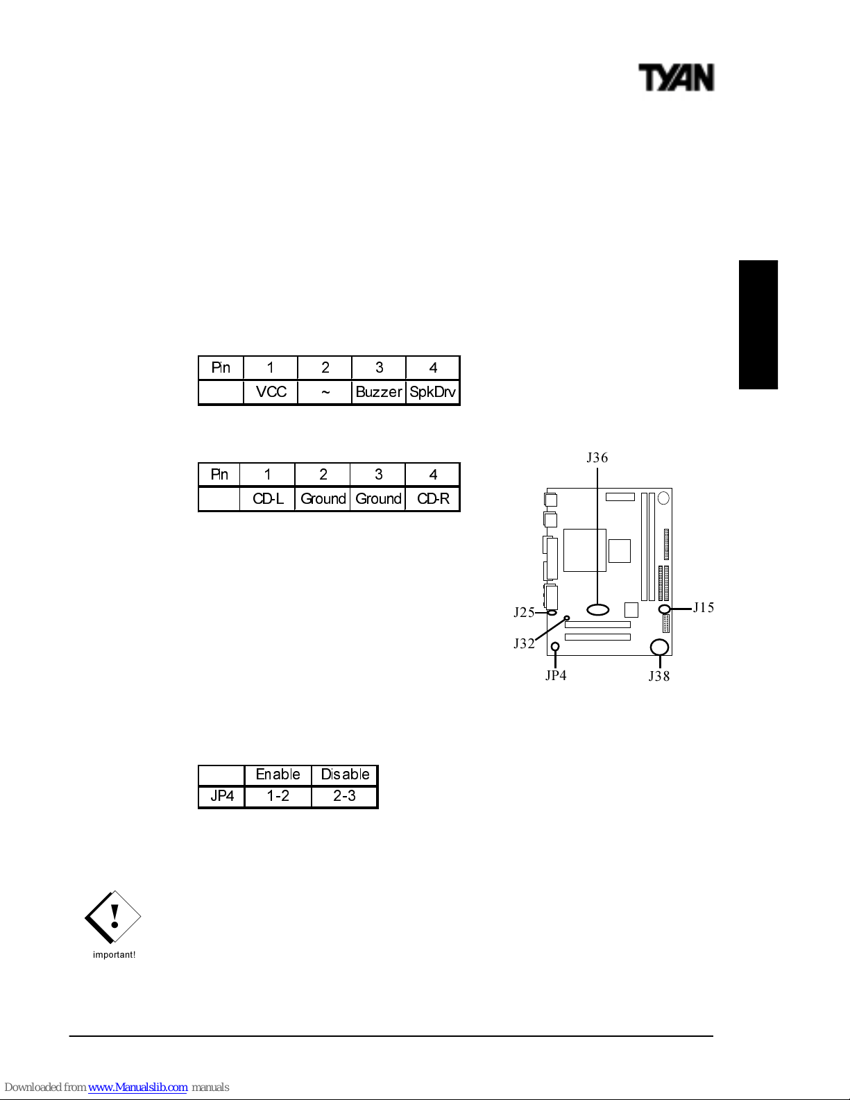
1-I. External Speaker Connector (J15)
The speaker should be connected to pins 1-4 of jumper J15.
1-J. CD Audio Connector (J32)
1-K. LCD Monitor Header (optional) (J36)
This is a 20-pin Silicon Image SII154 Digital videoout header for LCD Monitors.
1-L. COM2 port header (J25)
This is a connector header for the COM2 Port
(see map for detailed location)
1-M. On Board Sound Enable/Disable (JP4)
This jumper setting is Enabled by default
1-N. Frontside USB Header (J38)
Certain computer chassis allow for a front-end USB port connection.
Therefore, this board provides a front side USB header should you decide to
set up a USB connector at the front side of your computer. Note: If you use
J38, you will be unable to use the TOP USB port at the back of the
motherboard. Both J38 and USB1 share the same channel.
INSTALL
3LQ
9&& a %X]]HU 6SN'UY
3LQ
& '/ *URXQG *URXQG & '5
(QD E OH 'LV DE OH
-3
!
important!
J38
JP4
J36
J32
J25
J15
http://www.tyan.com
18
Chapter 2
Board Installation
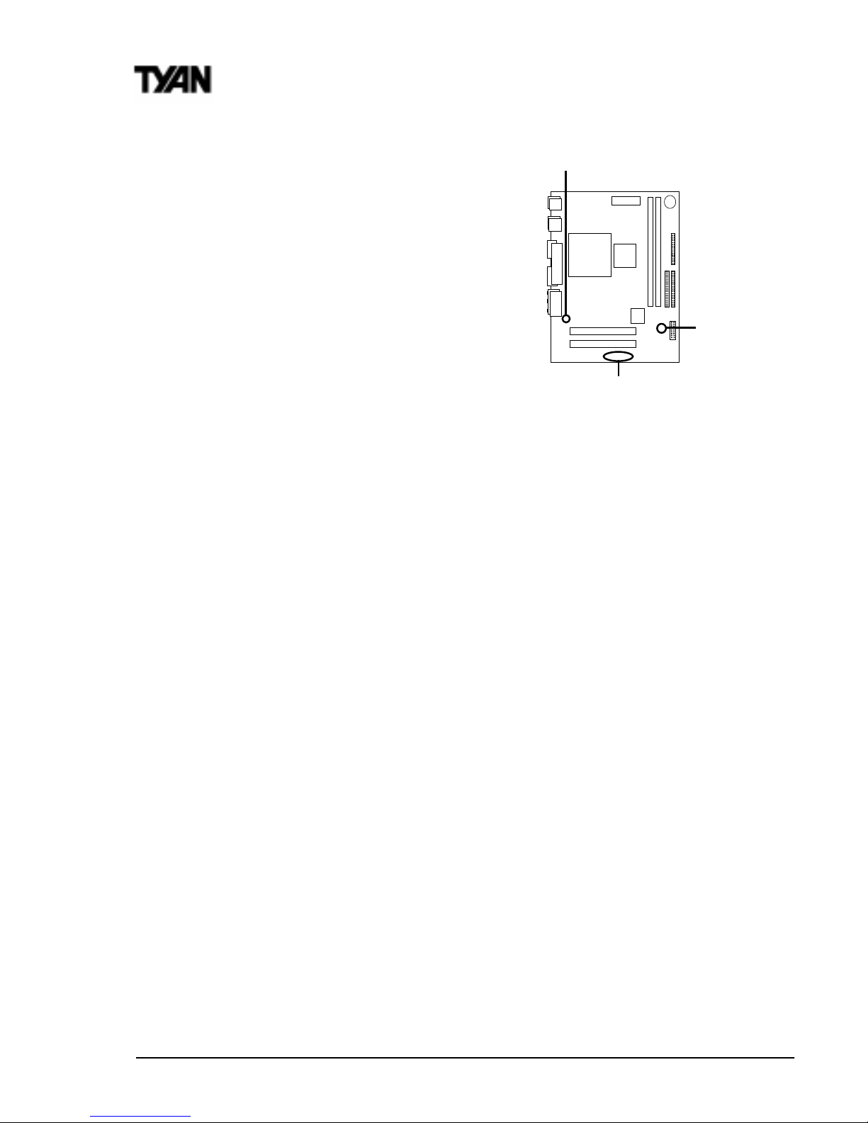
1-O. SCSI LED (J22)
This is the SCSI LED connector.
1-P. LAN LED (J45)
This is the LAN LED connector
1-Q. AUX Audio Connector (J44)
This connector is for plugging external audio
devices such as add on cards and other output
devices.
1-R. Server Management Connector (JP6)
The EXTSMI (External System Management Interface), connector JP6, is used
by some plug-in cards. Certain applications associated with these plug-in
cards use the interface for hardware control and queries.
Soft Power Connector
The Soft Power Connector is part of jumper block J9 (pins 6-8). The Tomcat
i810ef uses the chipset for power management, including turning on and off
the system. If the Power Button Function option in the BIOS Power Management Menu is set to On/Off (which is the default), pressing the power button
once after the BIOS has booted up will turn the system on and off. If the
Power Button Function option is set to Suspend, pressing the power button
once will wake the system or send it to Suspend mode. In this case, you
cannot turn the system off unless you shut down through the Windows
operating system or you hold the power button down for four seconds.
Hardware Reset Switch Connector Installation
The Reset switch on your cases display panel provides you with the Hardware Reset function, which is the same as power on/off. The system will do a
cold start after the Reset button is pushed.
CMOS RTC
The Real Time Clock (RTC) circuit, which provides the date and time for the
system is integrated into the 810e chipset. If the external battery for the RTC is
low, it will prevent your system from POSTing, and you will not get a display.
Normally the life span of an external battery is 2 years. If yours is running low,
you will need to replace it with a new 3V lithium battery (Sony CR2032).
J22
J44,
J45
JP6
S2420 Tomcat i810ef
19
2. Mounting the Motherboard in the Chassis
Follow the instructions provided by the case manufacturer for proper installation guidelines. Tyan recommends that you make use of all mounting holes to
screw down the motherboard. The adapter cards and the screws holding them
down will keep your board flat. The fastening screw should not short any of
the traces on the motherboard. Make certain that you do not overtighten the
screw, as it will damage the motherboard and possibly break internal traces in
the surrounding area. The hole you should use is located at the top-center of
the board where the adapter cards are fastened to the case.
3. Installing Memory
Since Tyan boards are manufactured with performance in mind, you should use
add-in components that match. Some DIMM modules may seem to be high
quality because of name or feel but that does not guarantee real-world
usability. Some cheaper or OEM memory may have brand-name components,
but they may contain inferior or substandard parts which do not meet the
critical tolerances our products require. Because of this, your memory may not
work correctly in a Tyan board though it may work well in a competitors board.
INSTALL
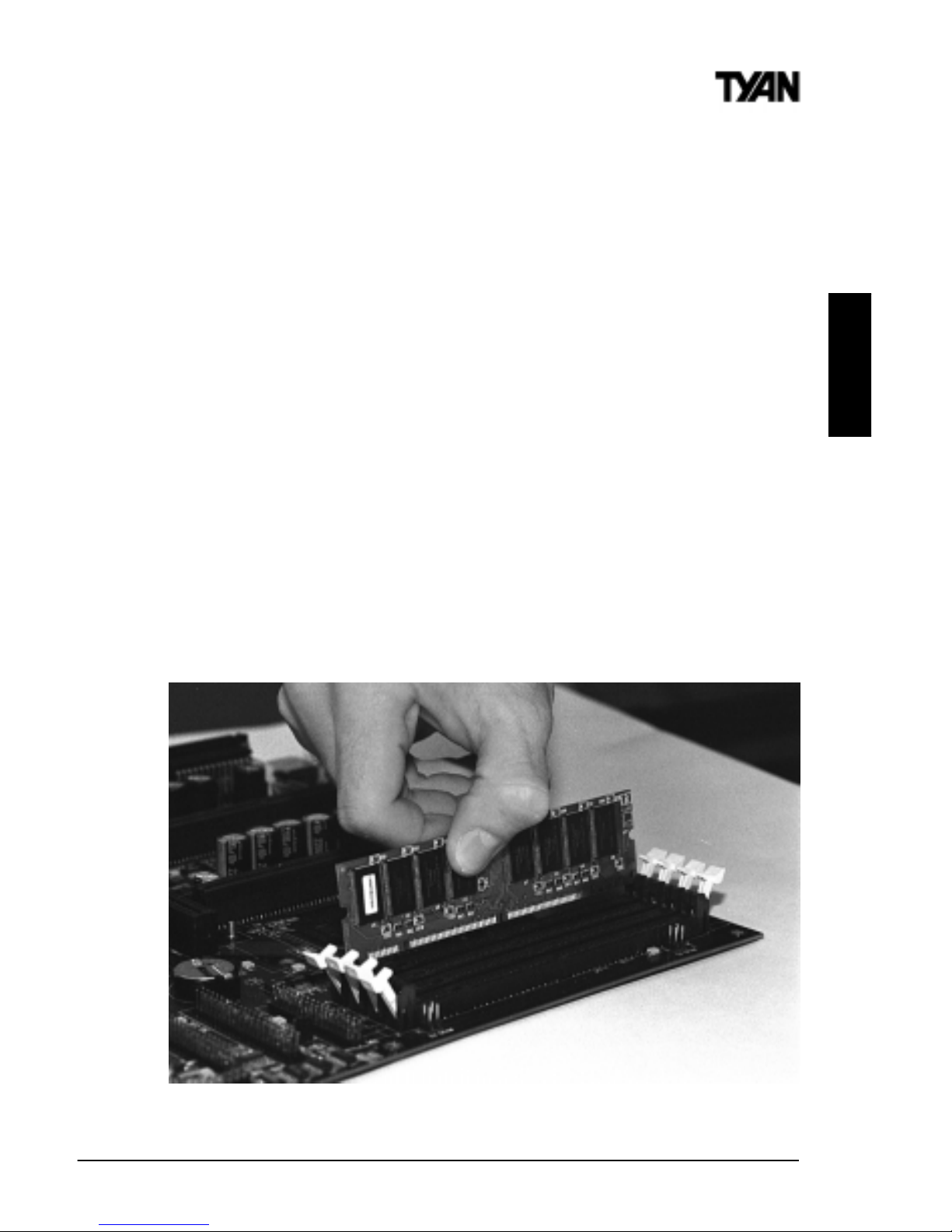
Figure 2-3
*Note: The image above is used to illustrate a concept and may not represent the actual
image of your motherboard.
http://www.tyan.com
20
Chapter 2
Board Installation
This is because many of our competitors do not adhere to the strict tolerances
required for high performance. If you buy a Tyan board, you are getting the
best system available. To make installation easy and trouble free, get high
quality parts. For a list of recommended memory vendors, please visit Tyans
website at www.tyan.com - go to the Memory Support area in the
Support Section. The website memory compatibility lists include DIMMs that
have proven to be very stable on our boards and perform extremely well.
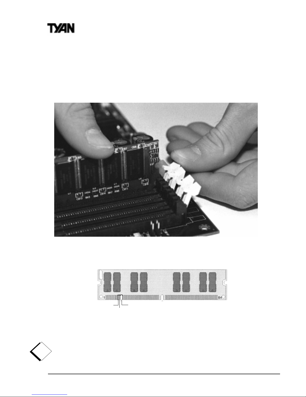
To install your DIMMs, line your module up so that the pins fit into the slot.
There is only one way that your DIMM can fit properly. Make sure that the
short row of pins is lined up with the short gap in the DIMM slot. Figure 2-3
(see previous page) shows how to sit the DIMM into its slot. To insert the
DIMM, push down vertically on the module with even force, as shown in the
photo. Do not shove one end in first; doing so will bend the DIMM pins.
RFU
Buffered
Unbuffered
168-pin DIMM
Figure 2-5
!
important!
Note: The image above is used to illustrate a concept and may not represent the actual
image of your motherboard.
Figure 2-4

S2420 Tomcat i810ef
21
INSTALL
To lock the DIMM into place, push the plastic clips on either end of the slot
onto the notches in the ends of the DIMM (see Figure 2-4 on previous page).
In some cases, pushing the memory module into the DIMM slot will move the
plastic clips inward, automatically locking the module into place. To remove
your DIMM, simply pull the clips back, and pull up on the module. Place the
DIMMs in an anti-static bag as soon as you remove them to avoid static
damage.
The Tomcat i810ef uses a 64-bit data path from memory to CPU and can
accommodate up to 512MB of SDRAM. The 168-pin DIMMs (Dual In-line
Memory Modules) must be of the 3.3V, PC-100, unbuffered variety. The
position of the notch in the SDRAM key position will tell you whether or not a
DIMM is unbuffered (see the Figure 2-5 on previous page). All installed
memory will be automatically detected, so there is no need to set any jumpers.
Some details of memory installation:
The mainboard supports 32MB, 64MB, 128MB SDRAM; and supports
256MB unregistered SDRAM DIMM modules.
PC-100 DIMM is required.
The table below shows some of the possible memory configurations. Not all
possible configurations are listed.
Warning! DO NOT use registered DIMMs. (Check with your memory
dealer for more information). See www.tyan.com for the latest memory
compatibility information.
1knaBMMID2knaBMMIDlatoT
1xBM231xBM23BM46
1xBM461xBM23BM69
1xBM461xBM46BM821
1xBM8211xBM46BM291
1xBM8211xBM821BM652
1xBM8211xBM652BM483
1xBM6521xBM652BM215
warning
http://www.tyan.com
22
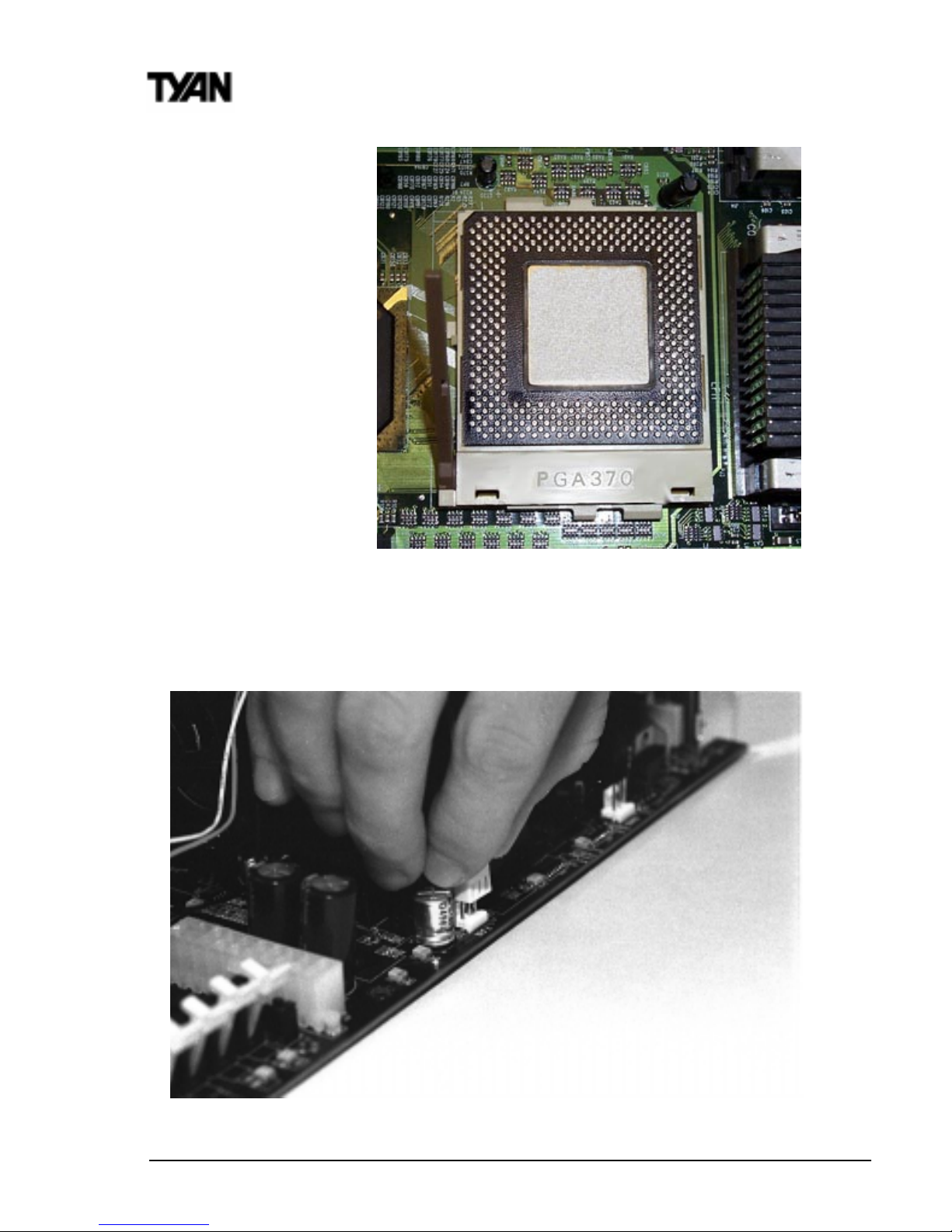
4. Installing the
CPU and Cooling Fan
Socket 370 Type processors can be used on the
Tomcat i810ef. Remember:
The CPU is a
sensitive electronic
component and it
can easily be
damaged by static
electricity.
Do not touch the
CPU pins with your
fingers.
Before the CPU is installed, the mainboard must be placed on a flat
surface. You should be able to insert the CPU into the slot with minimal,
but firm pressure. Do not press down hard on the CPU.
Figure 2-7
Chapter 2
Board Installation
Figure 2-6
 Loading...