

TYAN S2257 THUNDER 2400 User Manual

Tyan S2257
Thunder 2400
Motherboard Users Manual
Revision 1.10
Copyright © Tyan Computer Corporation, 2000. All rights reserved. No part of this
manual may be reproduced or translated without prior written consent from Tyan
Computer Corp.
All registered and unregistered trademarks and company names contained in this
manual are property of their respective companies including, but not limited to the
following.
AMIBIOS is a trademark of American Megatrend Incorporated.
Windows is a trademark of Microsoft Corporation.
IBM, PC, AT, PS/2 are trademarks of IBM Corporation.
INTEL, Pentium II/III, Celeron are trademarks of Intel Corporation.
S2257 Thunder 2400 is a trademark of TYAN Computer Corporation.
Information contained in this publication has been carefully checked for accuracy and
reliability. In no event will Tyan Computer be held liable for any direct or indirect,
incidental or consequential damage, loss of use, loss of data, or other malady resulting
from errors or inaccuracies of information contained in this manual. The information
contained in this document is subject to change without notice.
PRINTED IN USA

Table of Contents
1. Introduction....................................................................... 4
Overview...............................................................................................4
Icons..................................................................................................... 5
Hardware Specifications/Features....................................................6
Software Specifications......................................................................8
Technical Support............................................................................... 8
Returning Merchandise for Service................................................. 8
2. Board Installation.............................................................. 9
Unpacking............................................................................................ 9
Installation........................................................................................... 9
Quick Reference for Jumpers.............................................................11
Map of Motherboard Jumpers.......................................................... 12
Setting Jumpers................................................................................... 14
Clear CMOS & Reset Password........................................................15
Server Management Connector (External SMI)..............................15
Chassis Intrusion Alarm Connector................................................. 16
Audio Connectors.............................................................................. 16
Soft Power Connector......................................................................... 17
Hardware Reset Switch Connector Installation..............................18
CMOS RTC...........................................................................................18
Flash EEPROM.................................................................................... 18
Mounting the Motherboard in the Chassis.................................... 18
Installing Memory............................................................................... 19
Cache Memory..................................................................................... 22
Installing the CPU and Cooling Fan.................................................23
Connecting IDE and Floppy Drives................................................. 31
Connecting the Power Supply........................................................... 33
Installing Add-on Cards.................................................................... 34
Connecting PS/2, USB, Serial & Parallel Drivers............................ 35
Intel Ethernet Setup and Use............................................................ 36
Frequently Asked Questions............................................................ 49
3. BIOS Configuration...........................................................53
Main Setup...........................................................................................54
Advanced CMOS Setup.................................................................... 59
Chipset Setup...................................................................................... 64
Power Management Setup.................................................................68
Plug and Play Setup............................................................................73

Peripheral Setup.................................................................................. 77
Supervisor and User Security............................................................ 81
Language Utility.................................................................................. 82
Flash Writer Utility.............................................................................. 82
4. System Resources............................................................. 83
Beep Codes.......................................................................................... 84
Troubleshooting System Problems.................................................. 84
Displayed Error Messages................................................................ 85
Appendix 1 - CPU Retention Module Options............................................... 87
Appendix 2 - LSI SymBIOS Ultra2 LVD SCSI............................................. 89
Appendix 3 - Glossary .......................................................................................98
http://www.tyan.com
4
Chapter 1
Introduction
Overview
The Thunder 2400 is a quality, high performance motherboard designed for
Intel Pentium II and Pentium III microprocessors. This motherboard utilizes the
Intel 840 AGPset and can support CPU speeds of 350MHz through 750MHz
and host bus speeds of 100MHz or 133MHz (please see Tyans website for
up-to-date CPU support information).
The motherboard, with built-in AGP Pro slot, provides high performance
capabilities that are ideal for a wide range of demanding applications such as
CAD, CAM, CAE, desktop publishing, 3D animation, and video production.
This integrated high-performance system board is supported in an Extended
ATX form factor. Some of the features included are onboard UltraDMA33/66,
onboard dual channel Ultra2 (optional Ultra3) SCSI (LSI Symbios 53C896 chip),
optional onboard AC97 Codec Audio, onboard Intel Ethernet 82559, onboard
high speed I/O, and RAID support via one SISL (PCI) Slot.
With I/O and drive controller support built onboard, the one AGP Pro slot, six
PCI and one ISA slots (one shared, seven usable) are free for numerous addon expansion cards.
Remember to visit TYAN Computers web site at http://www.tyan.com. There
chapter 1
Introduction
S2257 Thunder 2400
5
you can find information on all of TYANs products along with FAQs, distributors list, drivers, and BIOS setting explanations.
Icons
In order to help you navigate this manual and set up your system, we have
added several icons to our format.
This icon alerts you to particularly important details regarding the setup or
maintenance of your system. This icon often appears next to
information that may keep you from damaging your board or
system. While we will often point out the most vital paragraphs in
a chapter, you should always read every word in the text. Failing
to do so can lead to exasperation and expense.
Wherever possible, we have included step-by-step instructions
for setting up your system, which are indicated by this icon.
However, it is in your best interest to read an entire section (and
perhaps the entire manual) before you begin to fiddle with your
motherboard.
While we have alerted you to potential dangers in several places
in the manual with this icon, these warnings should not be
regarded as the whole of your safety regimen. Never forget that
computers are electrical devices, and are capable of delivering a shock. Prevent
damage to yourself and to your board: always ensure that your system is
turned off and unplugged whenever you are working with it, and that you are
equipped with a static safety device.
!
important!
procedure
1.
2.
3.
warning
INTRO

http://www.tyan.com
6
Chapter 1
Introduction
Hardware Specifications/Features
Processor Information • Two SECC/SECC2 slots (Slot One type)
• 100MHz and 133MHz bus support
• Pentium II or Pentium III 350-750MHz*
• Two onboard VRMs (VRM 8.4 spec)
Chipset Information • Intel 840 AGPset - MCH+ICH+FWH (4Mb)
• Intel P64H to support 64-bit PCI slots
• National PC87 366 LPC Super I/O chip
BIOS Information • AMI BIOS on 4/8Mb Flash (FWH)
• APM 1.2 & ACPI 1.0
• Autodetection of memory size
• User settings of HW monitoring
• Auto configuration of IDE hard disk types
• Multiple boot options
• ACPI bi-color LED support
• DMI 2.0 compliant
Main Memory • Up to 4.0 GB onboard
• Four 3.3V unbuffered / Registered PC100
168-pin DIMM sockets
• Supports PC100 SDRAM with
SPD, and SDRAM+ECC
• Two MRH-S chips on board
Expansion Slots • One 2X / 4X AGP Pro slot
• Four 32-bit PCI Bus Master slots
• Two 64-bit 33/66 MHz 3.3V slots
• Seven total usable slots
Integrated PCI IDE • Two PCI bus mastering EIDE
channels
• Supports EIDE CD-ROMs
• PIO Mode 3 & 4 (up to 16.6 MB/sec DTR)
• UltraDMA33/66 bus mastering mode
(up to 66 MB/sec DTR)
* See TYAN website for CPU Compatibility List

S2257 Thunder 2400
7
INTRO
• Support for one floppy drive (Mode
1.44MB supported)
• Two serial ports (16550 UARTs)
• One ECP/EPP parallel port
• One IR (InfraRed) I/O interface port (shared
with Com2)
• Two USB rev 1.1 ports
• One PS/2 mouse port
• One PS/2 keyboard port
Onboard Ultra2 SCSI • LSI Symbios 53C896 dual channel Ultra2
LVD SCSI
• Two 68-pin high density Ultra2 SCSI ports
• One 50-pin legacy connector
Onboard Ethernet • Intel 82559 10/100 Ethernet onboard
• Full Wake-on functionality (Requires ATX
2.01 power supply)
• One RJ-45 ATX connector
Intergated Audio • AC97 CODEC
• ATX Joystick, Audio in, Speaker, Micro-
phone connectors
System Hardware · Onboard hardware for monitoring
Management temperature, supply voltages, and fan
speed
· Intel LANDesk Client Manager
software
· Chassis intrusion detection capable
Voltage and Power • ATX power supply connector
Information • +12V power source for DC fan onboard
• 3.3V DRAM support
• Utilizes GTL+ bus to reduce power
consumption and EMI
Physical Dimensions • Extended ATX design
• 13 inches x 12 inches

http://www.tyan.com
8
Chapter 1
Introduction
Software Specifications
OS • Operates with Windows 98/ SE,
Windows NT 4.0, Novell Netware, and
SCO Unix.
Technical Support
If a problem arises with your system, you should turn to your dealer for help
first. Your system has most likely been configured by them, and they should
have the best idea of what hardware and software your system contains.
Hence, they should be of the most assistance. Further, if you purchased your
system from a dealer near you, you can actually bring your system to them to
have it serviced, instead of attempting to do so yourself (which can have
expensive consequences).
Help resources:
1. See FAQ and beep codes sections of this manual.
2. See Tyan web site for FAQ, bulletins, driver updates, etc.
http://www.tyan.com
3. Contact your dealer or distributor for help BEFORE calling Tyan.
4. Check the Tyan user group: alt.comp.periphs.mainboard.tyan
Returning Merchandise for Service
During the warranty period, contact your distributor or system vendor FIRST
for any product problems. This warranty only covers normal customer use and
does not cover damages incurred during shipping or failure due to the
alteration, misuse, abuse, or improper maintenance of products.
For Resellers Only:
A receipt or copy of your invoice marked with the date of purchase is required
before any warranty service can be rendered. You can obtain service by calling
the manufacturer for a Return Merchandise Authorization (RMA) number. The
RMA number should be prominently displayed on the outside of the shipping
carton and the package should be mailed prepaid, or hand-carried to the
manufacturer. TYAN will pay to have the board shipped back to you.
S2257 Thunder 2400
9
chapter 2
Board Installation
Unpacking
The retail motherboard package should contain the following:
• S2257 motherboard
• One 40-pin IDE and 34-pin floppy cable pack
• Users manual
• One 3-head Ultra2 SCSI cable w/ terminator (cables with 4 heads or longer
must be ordered separately)
• One 3-head regular SCSI cable
• Two CPU retention modules
• One ATX I/O Shield
• One System Management & Driver CD; includes complete drivers for
SCSI, LAN and audio controllers
• One gameport cable
• One Driver Diskette for LSI Symbios 53C896
• One Slot 1 Terminator Card.
Installation
You are now ready to install your motherboard. The mounting hole pattern of
the Thunder 2400 matches the ATX system board specifications. Your chassis
should be that of an extended ATX motherboard form factor.

http://www.tyan.com
10
How to install our products right...the first time.
Whats the first thing I should do?
The first thing you should do is read this users manual. It contains important
information which will make configuration and setup much easier.
Here are some precautions you should follow when installing your motherboard:
(1) Ground yourself properly before removing your motherboard
from the antistatic bag. Unplug the power from your computer
and then touch any metal part on the computer case. (Or wear a
grounded wrist strap.)
(2) Hold the motherboard by its edges and do not touch the bottom of
the board.
(3) Avoid touching motherboard components, IC chips, connectors,
and leads.
(4) Avoid touching pins of memory modules and chips.
(5) Place motherboard on a grounded antistatic surface or on the
antistatic bag.
Having reviewed the precautions above, the next step is to take the motherboard out of the cardboard box and static bag, hold it by its edges, and place it
on a grounded antistatic surface, component side up. Inspect the board for
damage.
DO NOT APPLY POWER TO THE BOARD IF IT HAS BEEN DAMAGED!
Press down on any of the socket ICs if it appears that they are not properly
seated (the board should still be on an antistatic mat). Do not touch the bottom
of the board. Remember, dont take any electronic device out of its protective
bag until you are ready to actually install it into the computer case. If you do
not ground yourself, you risk zapping the motherboard or adapter card.
Subsequent problems may not arise immediately because electrostatic discharge damage, unlike physical damage, causes the device to fail over time.
*Power Supply Requirement: ATX Power Supply should be 2.01 compliant.
Standby current must be 750mA or higher (SB5V = 0.75A)
procedure
1.
2.
3.
!
important!
Chapter 2
Board Installation

S2257 Thunder 2400
11
INSTALL
Installation Steps
1. Set Jumpers / Dip Switch
2. Mount Motherboard in Chassis
3. Install Memory
4. Install CPU & Cooling Fan
5. Connect IDE and Floppy Drives
6. Connect Power Supply
7. Install Add-on Cards
8. Connect PS/2, USB, Serial and Parallel Devices
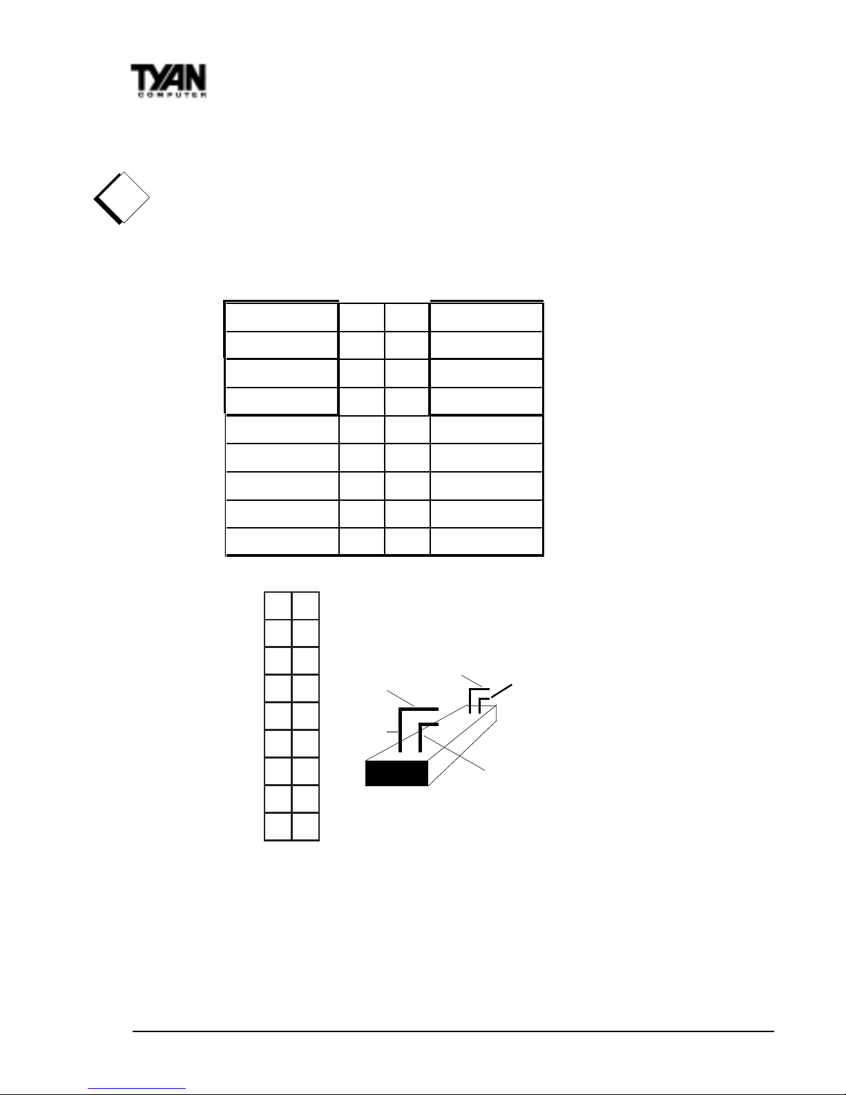
Quick References for Jumpers
In this manual, the terms closed and on are used when referring to jumpers
(or jumper pins) that are active; open and off are used when referring to
jumpers (or jumper pins) that are inactive. See the Figure 2-1 for examples of
on and off pins and jumpers. The square pin in the diagram is Pin 1.
Jumpers and pins are connected by slipping the blue plastic jumper connector
overtop of two adjacent jumper pins (indicated by 1-2 or 2-3). The metal rod
inside the plastic shell bridges the gap between the two pins, completing the
circuit. See Figure 2-2 for more examples of pin connections.
The tables and maps on the following pages will help you set the jumpers for CPU
speed, Infrared, and external connector pin assignments, among others. The
miniature motherboard maps will help you locate the jumpers on your board. A
full-page map of the motherboard can be found on the next two pages.
2 pin jumpers
off on
3 (or more) pin jumpers
1-2 2-3 open
1
2
3
1
2
3
1
2
3
Figure 2-1
Figure 2-2
procedure
1.
2.
3.
http://www.tyan.com
12
Chapter 2
Board Installation
The tiny 1s next to jumpers of 3 pins or more indicate the position of pin 1 for
that jumper.
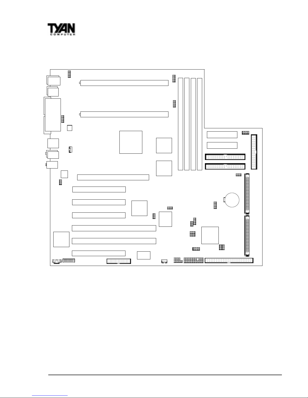
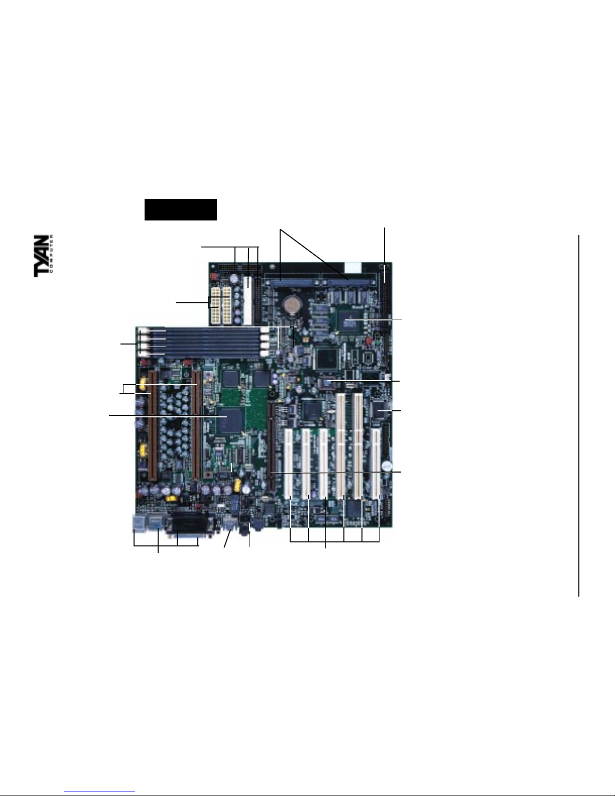
Map of Motherboard Jumpers
COM1
Secondary IDE connector
Primary IDE connector
Floppy connector
Narrow SCSI Channel B
USB1
Keyboard
USB2
Mouse
COM2
JP2
JP3
AMI
BIOS
J44
J33
J1
1
1
1
1
1
1
Ethernet
FAN6
1
FAN3
Printer Port
1
J51
FAN7
Speaker
1
CPU 2 slot (Slot One type)
Intel
840 Chipset
MCH
Ultra2 SCSI Channel A
Ultra2 SCSI Channel B
ATX power supply
ATX power supply
J49 J50
Super
I/O
Intel
P64H
LSI
53C896
PCI slot 1
PCI slot 2
CPU 1 slot (Slot One type)
MIC
Line In
AGP Pro slot
PCI slot 3
PCI slot 6
Winbond
83782
DIMM bank 2
DIMM bank 3
DIMM bank 4
DIMM bank 1
3 volt
J7
J12
CPU2 FAN
CPU1 FAN
64-bit PCI slot 5
64-bit PCI slot 4
J15
FAN5
1
FAN4
J2
1
J32
J28
J38
Intel
ICH Chip
J26
J52
J55
1
1
1
1
1
Intel
MRH-S
Intel
MRH-S
Intel
82559
S2257 Thunder 2400
13
INSTALL
Intel i840 Chipset
4 DIMM slots
2 SECC slots
2 Wide SCSI channels 1 Narrow SCSI channel
LSI Symbios
U2 SCSI
AMIBIOS
6 PCI slots
Ethernet
AGP Pro port
IDE and Floppy
connectors
Double row ATX connectors
ATX Power supply
connectors
Speaker/
Line In
Winbond
W83782D
http://www.tyan.com
14
Chapter 2
Board Installation
!
important!
1. Setting Jumpers
1-A. CPU Speed Settings
There are no settings for the CPU Frequency, Multiplier, Voltage and
Frontside Bus Speeds. These are all auto-detected throught the CPU.
1-B. Front Panel Assignment (Jumper J12)
*Power LED: For 2-pin: bicolor/single color LED - Use pins 2-4
For 3-pin: bicolor LED - Use Jumper J7
12
34
56
78
901
1121
3141
5161
7181
Top
Bottom
Top Pin
Bottom Pin
JP32 Side View
JP12
Pin1
Pin17
Pin2
VCC 12 Powe r LE D
HDD LE D 34 Sleep LED
Ground 56Pow er On/Of f
Rese t 78 Ground
VCC 910 No Connect
IR Receive 11 12 VCC
Ground 13 14 No Connect
IR Transmit 15 16 VCC
No Conn e ct 17 18 No Connect

S2257 Thunder 2400
15
INSTALL
1-C. Clear CMOS and Reset Password (Jumper JP2)
If you have been locked out of your system because you forgot your password or set the CMOS incorrectly, follow the instructions below.
1. Power off the system
2. Set jumper JP2 to pins 2 and 3 (see page 12 for location of JP2).
3. Wait for at least 2 seconds, then return jumper JP2 to pins 1 and 2.
4. Power on the system again.
By following this procedure, you will erase your password and reset the
CMOS to the BIOS defaults.
1-D. Speaker Connector (Jumper J15)
The speaker should be connected to jumper J15. As default, jumper J15
should be connected to enable the internal buzzer.
1-E External HardDrive LED (Jumper J26)
The HDD LED should be connected to jumper J26. This will provide monitoring of the Hard drive status on the Chassis.
1-F. Wake-On Ring Connector (J28)
* WOR connector at the time of print has not been tested.
1-G. Wake-On LAN Connector (J2)
1-H. Server Management Connector (J38)
The EXTSMI (External System Management Interface) connector, jumper J38,
is used by some plug-in cards. Certain applications associated with these plugin cards use the interface for hardware control and queries.
'HIDXOW 5HV HW
-3
3LQ
96% *URXQG :25
3LQ
96% *URXQG :2/
http://www.tyan.com
16
Chapter 2
Board Installation
1-I. Chassis Intrusion Alarm Connector (J1)
The J1 connector is an intrusion alarm, that can be connected to the system
chassis. When active (J1 is connected to the chassis), this alarm will alert the
system administrator anytime someone opens the systems case.
1-J. CPU1, CPU2, Fan3, Fan4, Fan5, Fan6, FAN7 - Pinout
- CPU1 connector corresponds to CPU 1 slot.
- CPU2 connector corresponds to CPU 2 slot.
- Fan4 / Fan6 are Chassis Fans
- Fan3, 5, 7 = connector header
Note: With Intels LANDesk system monitoring software, only two fans can be
monitored at one time.
When using Intels LANDesk system management software, you may monitor
the status of the CPU Fans by connecting them to the CPU1 and/or CPU2
connectors. You will NOT be able to monitor your CPU fan with the other Fan
connectors.
1-K. CD Audio Connector Audio Connectors (J33)
This is a 4-pin connector onboard which is used for audio signals. The digital
signal that comes in through these connectors is directed through the Ensoniq
1373 PCI sound chip, and the digital signal is turned into an audio signal which
goes out through the speaker.
1-L. Gameport Connector (J32)
This connector connects to the game port cable provided with the
motherboard. The cable is then mounted onto the chassis onto one of the
ports located on the back of the chassis. You may use this port to connect
devices such as a joystick or gamepad.
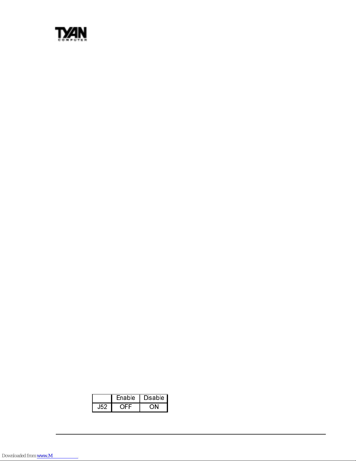
1-M. Disable SCSI (J52)
To disable the onboard SCSI, jumper J52 must be closed. Default for this
jumper is to be left open.
(QDEO H 'L VDEOH
- 2)) 21
S2257 Thunder 2400
17
INSTALL
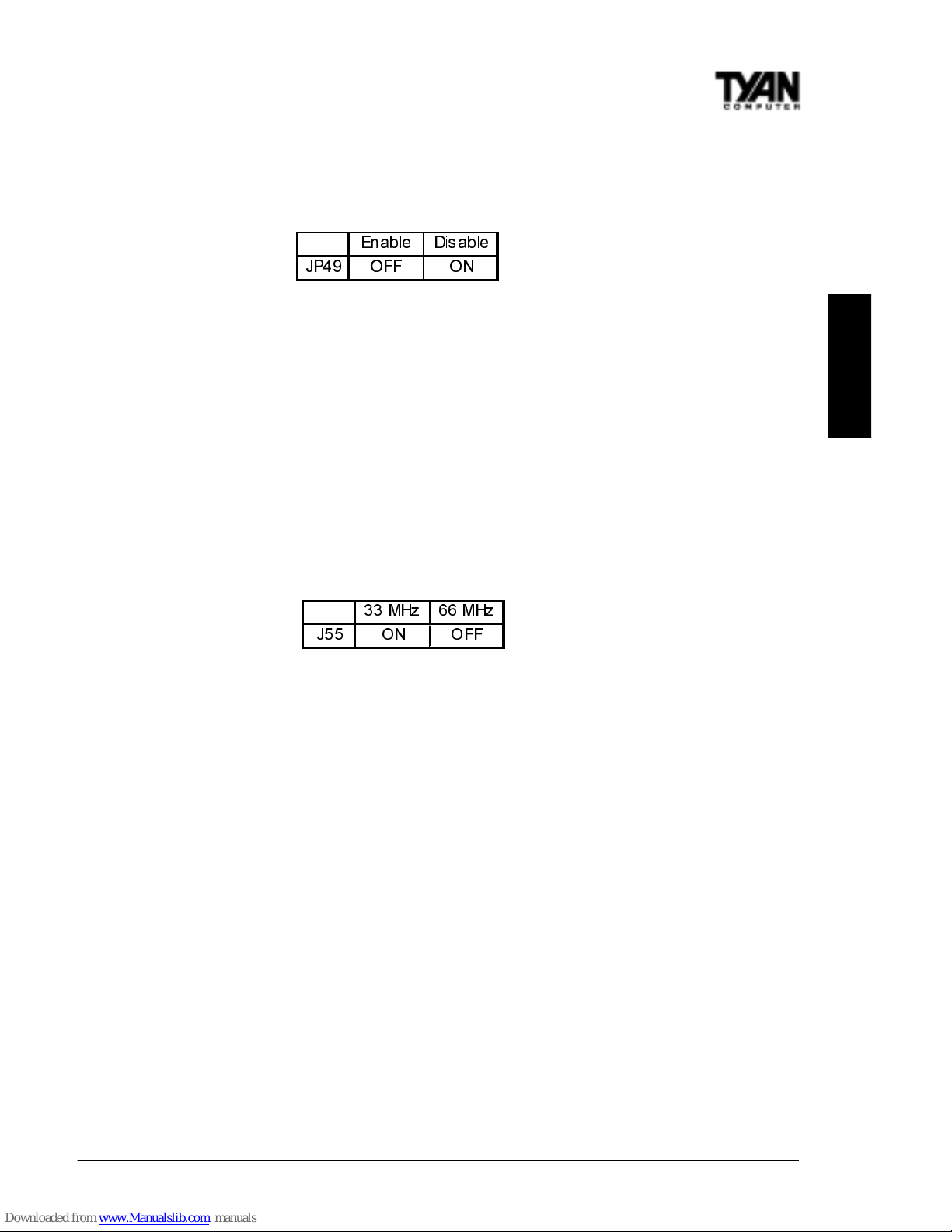
1-N. Narrow SCSI Termination (J49)
To terminate the 50 pin Narrow SCSI Connector jumper J49 must be open.
Default is open.
1-O. SCSI Channel B (J50) Channel A (J51) force to SE Mode
Some SCSI devices cannot be detected under Ultra-2 SCSI standards and may
cease to function properly when used on either Channel A or Channel B. If this
should happen, you would need to force that particular channel to Single End
mode in order to allow the device to be detected. Please bear in mind that the
data transfer rate of Single end SCSI mode is 40 MB/Sec whilst Ultra-2 is at 80
MB/Sec.
1-P. 64bit PCI Bus Frequency (J55)
The two 64bit PCI slots located on the board are capable of functioning at both
33 MHz and 66 MHz. The default setting for jumper J55 is closed and the slot
runs at 33 MHz. To set the BUS speed to 66 Mhz, J55 must be opened.
1-Q Boot Block Write-Protect (JP3)
The Boot block contains information concerning how the system will POST.
JP3 is open by default which prevents writing to the Boot Block. If modifications need to be made, JP3 must be closed in order to disable write-protection.
1-R Enable/Disable LAN (J44)
This jumper allows you to enable the onboard LAN function. Default is
enabled (open).
Soft Power Connector
The Soft Power Connector is part of jumper block J12. The Thunder 2400 uses
the chipset for power management, including turning on and off the system. If
the Power Button Function option in the BIOS Power Management Menu is
set to On/Off (which is the default), pressing the power button once after the
BIOS has booted up will turn the system on and off. If the Power Button
Function option is set to Suspend, pressing the power button once will wake
the system or send it to Suspend mode. In this case, you cannot turn the
system off unless you shut down through the Windows operating system or
you hold the power button down for at least four seconds.
(QD EOH 'LV DEOH
-3 2)) 21
0+] 0+]
- 21 2 ))

http://www.tyan.com
18
Chapter 2
Board Installation
Hardware Reset Switch Connector Installation
The Reset switch on your cases display panel provides you with the Hardware Reset function, which is the same as power on/off. The system will do a
cold start after the Reset button is pushed.
CMOS RTC
The Real Time Clock (RTC) circuit, which provides the date and time for the
system is integrated into the i840 AGPset. If the external battery for the RTC is
low, you will most likely lose your BIOS settings. Normally the life span of an
external battery is 2 years. If yours is running low, you will need to replace it
with a new 3V lithium battery (CR2032).
Flash EEPROM
The Thunder 2400 uses flash memory to store BIOS firmware. It can be
updated as new versions of the BIOS become available. You can upgrade your
BIOS easily using the flash utility (see page 82).
2. Mounting the Motherboard in the Chassis
Follow the instructions provided by the case manufacturer for proper installation guidelines. TYAN recommends that you make use of all mounting holes to
screw down the motherboard. The adapter cards and the screws holding them
down will keep your board flat. The fastening screw should not short any of
the traces on the motherboard. Make certain that you do not overtighten the
screw, as it will damage the motherboard and possibly break internal traces in
the surrounding area. The hole you should use is located at the top-center of
the board where the adapter cards are fastened to the case.

S2257 Thunder 2400
19
INSTALL
3. Installing Memory
Since TYAN boards are manufactured with performance in mind, you should
use add-in components that match. Some DIMM modules may seem to be high
quality because of name or feel but that does not guarantee real-world
usability. Some cheaper or OEM memory may have brand-name components,
but they may contain inferior or substandard parts which do not meet the
critical tolerances our products require. Because of this, your memory may not
work correctly in a TYAN board though it may work well in a competitors
board. This is because many of our competitors do not adhere to the strict
tolerances required for high performance. If you buy a TYAN board, you are
getting the best system available. To make installation easy and trouble free,
get high quality parts. For a list of recommended memory vendors, please visit
Tyans website at www.tyan.com - go to the Memory Support area in the
Support Section. The website memory compatibility lists include DIMMs that
have proven to be very stable on our boards and perform extremely well.
http://www.tyan.com
20
Chapter 2
Board Installation
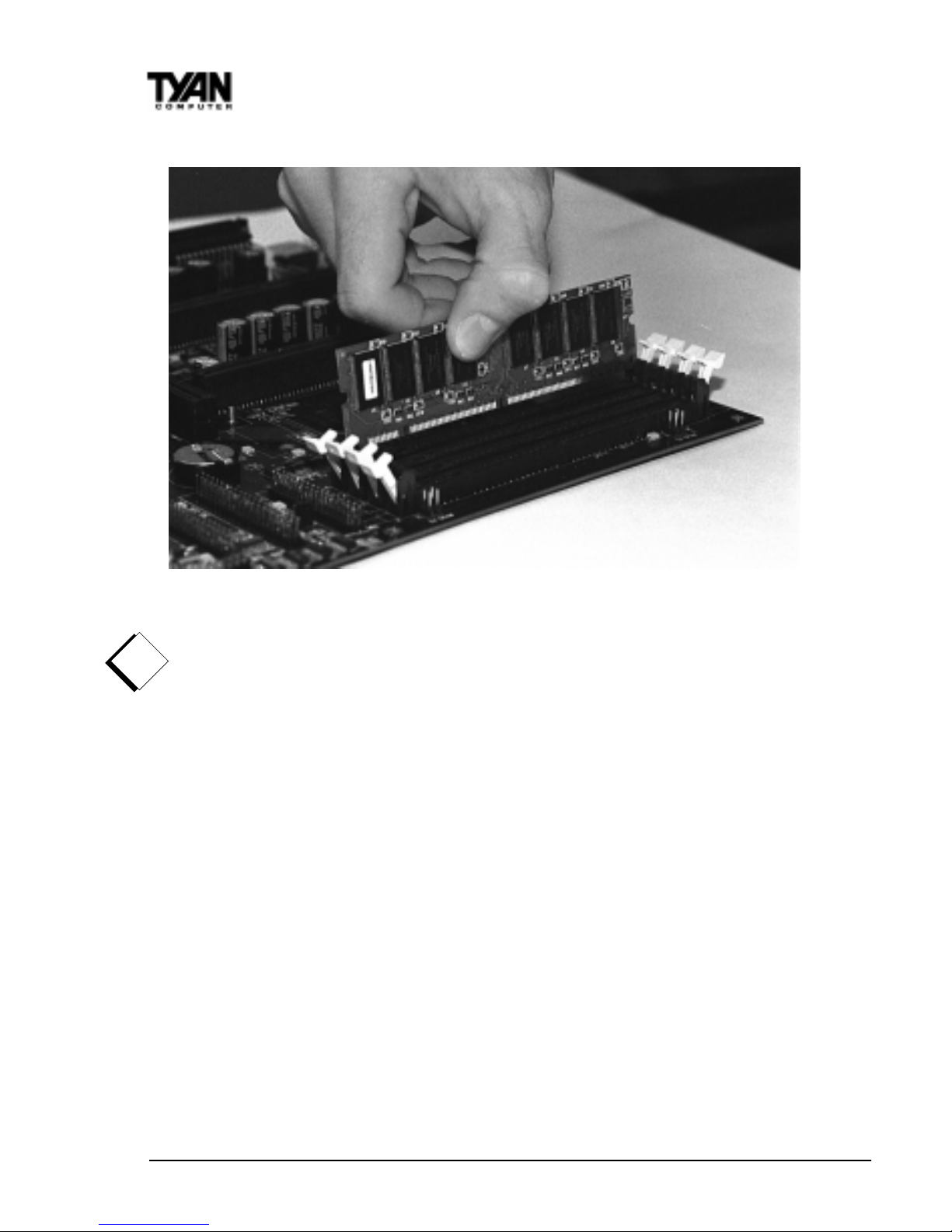
Figure 2-3
To install your DIMMs, line your module up so that the pins fit into the slot.
There is only one way that your DIMM can fit properly. Make sure that the
short row of pins is lined up with the short gap in the DIMM slot. Figure 2-3
above shows how to sit the DIMM into its slot. To insert the DIMM, push
down vertically on the module with even force, as shown in the photo. Do not
shove one end in first; doing so will bend the DIMM pins.
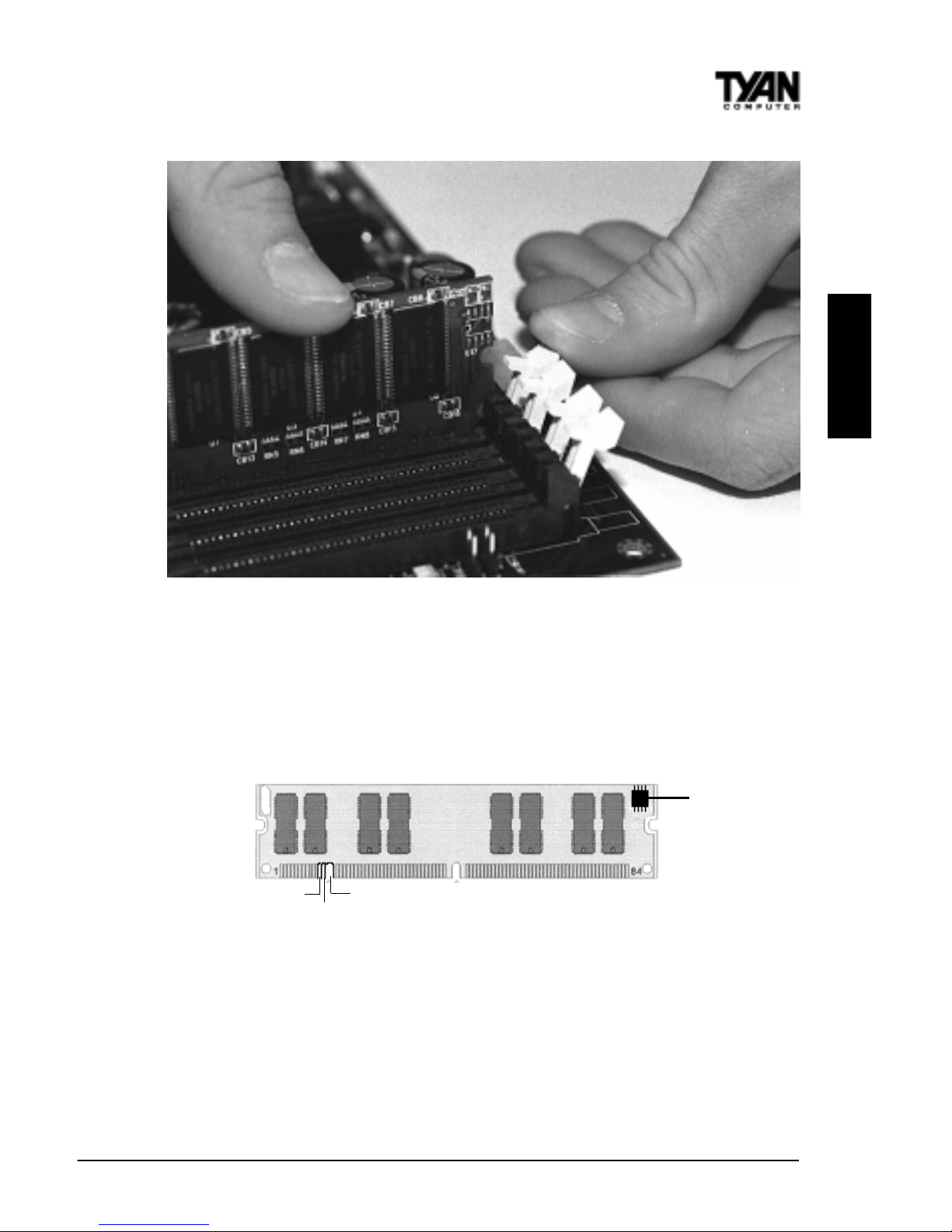
To lock the DIMM into place, push the plastic clips on either end of the slot
onto the notches at the ends of the DIMM (see Figure 2-4 on the next page).
In some cases, pushing the memory module into the DIMM slot will move the
plastic clips inward, automatically locking the module into place. To remove
your DIMM, simply pull the clips back, and pull up on the module.
Place the DIMMs in an antistatic bag as soon as you remove them to avoid
static damage.
!
important!
S2257 Thunder 2400
21
INSTALL
Figure 2-4
The Thunderbolt uses a 64-bit data path from memory to CPU and can
accommodate up to 4 GB of SDRAM. The 168-pin DIMMs (Dual In-line
Memory Modules) must be of the 3.3V, unbuffered variety. The position of the
notch in the SDRAM key position will tell you whether or not a DIMM is
unbuffered (see the Figure 2-5 below). All installed memory will be automatically detected, so there is no need to set any jumpers.
Some details of memory installation:
The mainboard supports 32MB, 64MB, 128MB SDRAM; and supports
256MB registered SDRAM DIMM modules.
PC-100 DIMM is required if CPU bus speed is at 100MHz
The board supports registered or nonregistered memory chips. DO NOT
mix registered and nonregistered memory chips on the motherboard.
RFU
Buffered
Unbuffered
Figure 2-5
EEPROM
http://www.tyan.com
22
Chapter 2
Board Installation
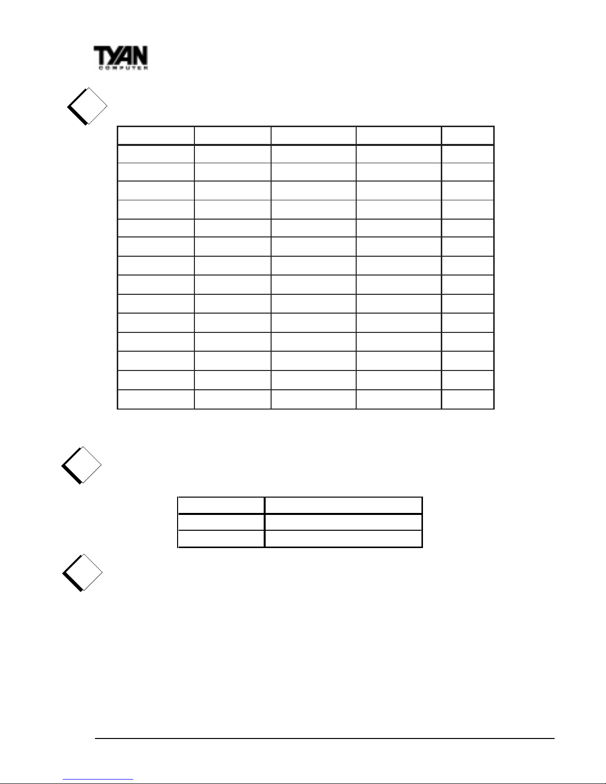
The table below shows some of the possible memory configurations. Not all
possible configurations are listed.
* 1GB modules have not be verified at time of print.
Attention: Due to specific memory population, the DIMM modules must to be
inserted as pairs. In order for the board to Post please install the DIMMS in
the combination shown below. All DIMM modues must be the same size.
Warning! The 256MB DIMMs represented in the table are REGISTERED
memory chips. DO NOT use registered and nonregistered memory chips
simultaneously! (Check with your memory dealer for more information).
See www.tyan.com for latest memory compatibility information.
Cache Memory
Intels Celeron/ PII and PIII processors have the L2 (Level 2) cache built into
their architecture, so there is no need for an L2 cache on the motherboard. The
processors have a physical L2 cache size of 128KB up to 512KB and a
cacheable memory area of 512MB.
!
important!
!
important!
1knaBMMID2knaBMMID3knaBMMID4knaBMMIDlatoT
1xBM460 1xBM460BM821
1xBM461xBM461xBM461xBM46BM652
1xBM821
0
1xBM821
0652
BM
0
1xBM821
0
1xBM821
652
BM
1xBM8211xBM8211xBM8211xBM821BM215
1xBM652
0
1xBM652
0
BM215
0
1xBM652
0
1xBM652BM215
1xBM6521xBM6521xBM6521xBM652
BM4201
1xBM215
0
1xBM215
0BM4201
0
1xBM215
0
1xBM215
BM4201
1xBM2151xBM2151xBM2151xBM215
8402
BM
1*
20
1xBM4
0*
1
20
1xBM4
08402
BM
0
1*
20
1xBM4
0*
1
20
1xBM4
8402
BM
1*
20
1xBM41*
20
1xBM4
*120
1xBM4
*120
1xBM4
BG4
1RRI',0 06 ',0 0 %$ 1.FRP ELQDWLRQ
DQGRUDQG
DOOEDQNV DQG
!
important!
S2257 Thunder 2400
23
4. Installing the CPU and Cooling Fan
Pentium II or Pentium III processors can be used on the Thunder 2400. Please
refer to pages 14-18 for the correct CPU jumper settings for your board. Remember:
• The CPU is a sensitive electronic component and it can easily be damaged
by static electricity. Do not touch the CPU pins with your fingers.
• Before the CPU is installed, the motherboard must be placed on a
flat surface. You should be able to insert the CPU with minimal, but
firm, pressure. Do not press down hard on the CPU.
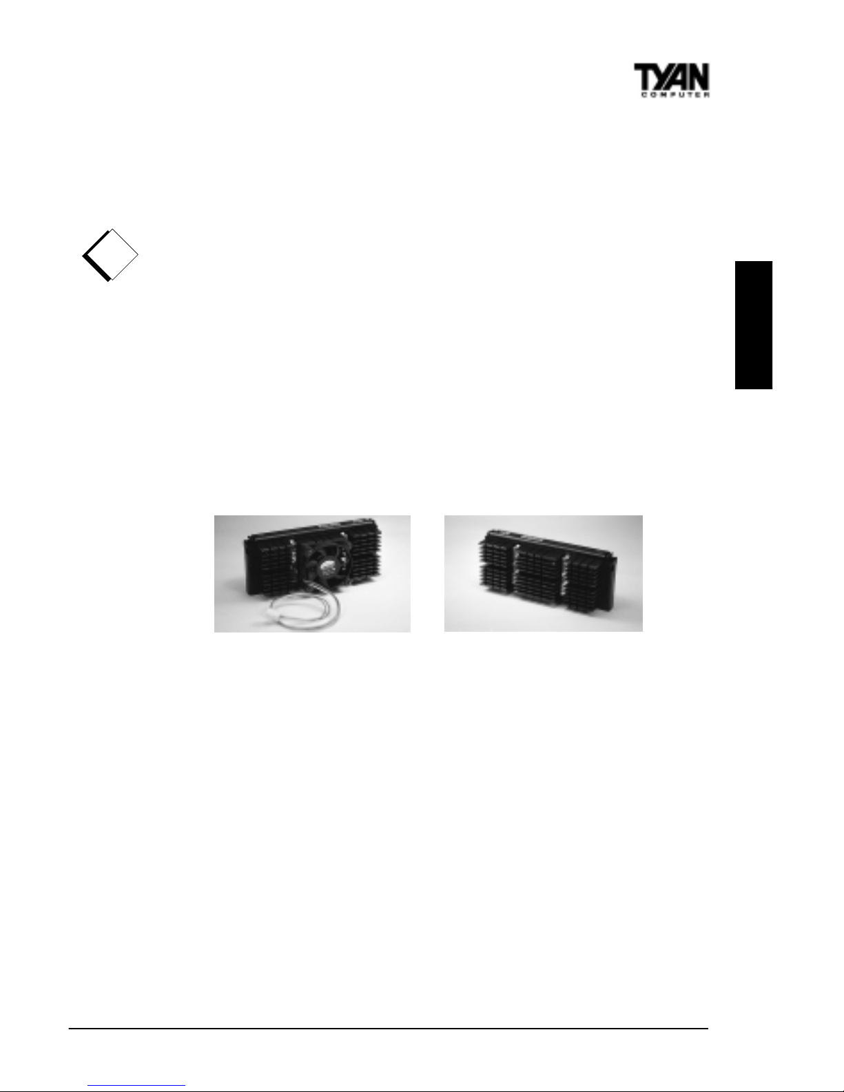
There two types of cooling mechanisms are produced for Pentium II processors: active (figure 2-6a) and passive (figure 2-6b). These two types of cooling
methods essentially perform the same function. The active cooler is equipped
with a cooling fan and heat sink, while the passive cooler is simply a larger
heat sink with no fan. The type of cooler used has no effect on performance,
and both types can be installed in the CPU slot on the Thunderbolt board.
Figure 2-6a Figure 2-6b
Installing CPU Retention Modules
Installation of a Pentium II / III processor requires a CPU retention module,
which is first secured onto the motherboard. Tyan offers a variety of retention
mechanisms for the different CPU types. See Appendix 1 for options.
!
important!
INSTALL
http://www.tyan.com
24
To attach the retention module, place
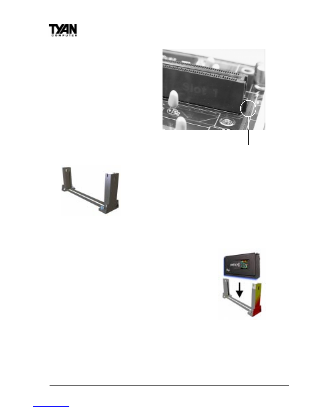
the motherboard on a flat surface.
Locate the key pin on one end of the
CPU slot on the board. Then carefully
line up the key notch on the retention
module with the key pin on the CPU
slot (the key pin on the CPU slot
indicates the correct orientation of the
CPU) See Figure 2-8.
Drop the retention module (Figure 2-9) down over
the CPU slot so that the retention module sits flat
against the motherboard. Tighten the screws in a
clockwise manner to secure the module to the
board. Warning: Do not overtighten the screws as
you may damage the module and/or the motherboard.
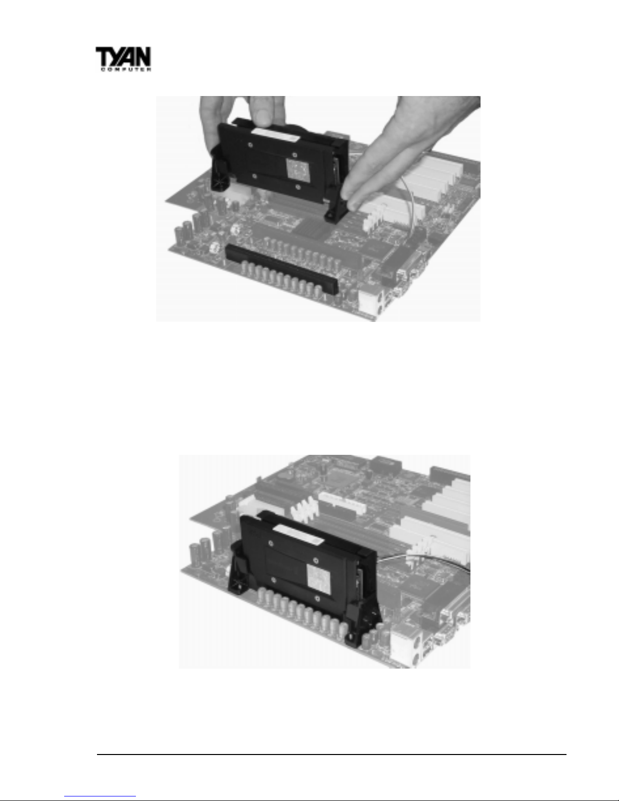
Installing the CPU with Active Cooling
When the retention module is securely installed, you are ready
to plug in the CPU. Press down firmly on the CPU until you
hear a click (see Figure 2-10). This clicking sound indicates
that the CPU is fully locked into the retention module. If you
have an active cooler, you will also need to connect the CPUs
cooling fan cable to the cooling fan power connector on the
board.
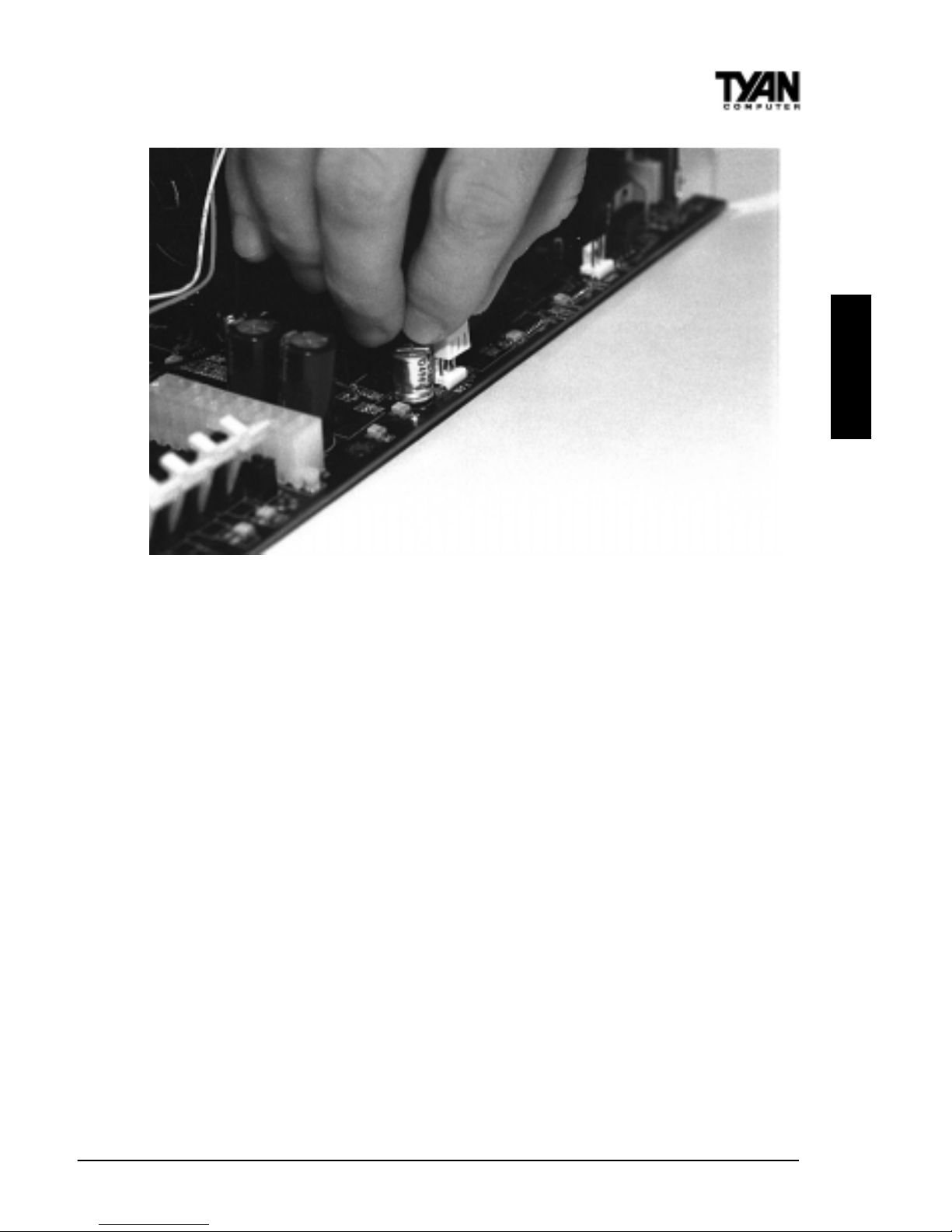
Locate the cooling fan connector (e.g. CPU1) on the motherboard. Plug the CPUs cooling fan cable into the cooling fan
connector on the board. There will be a plastic clip assembly
similar to that of the ATX power connector that will force you
to connect the fan cable correctly (see Figure 2-11 on the following page).
Figure 2-8 - Pentium II Slot Connector and Key Pin
Figure 2-9
Figure 2-10
Chapter 2
Board Installation
S2257 Thunder 2400
25
Figure 2-11
Removing the CPU.
To remove the CPU, move the locks to the center of the CPU. A click will be
heard when the CPU has been unlocked. Gently pull up on the CPU, taking care
not to bend the motherboard or the CPU retention module.
To remove the lock from the retention module, gently press the ends of the locks
inward and pull.
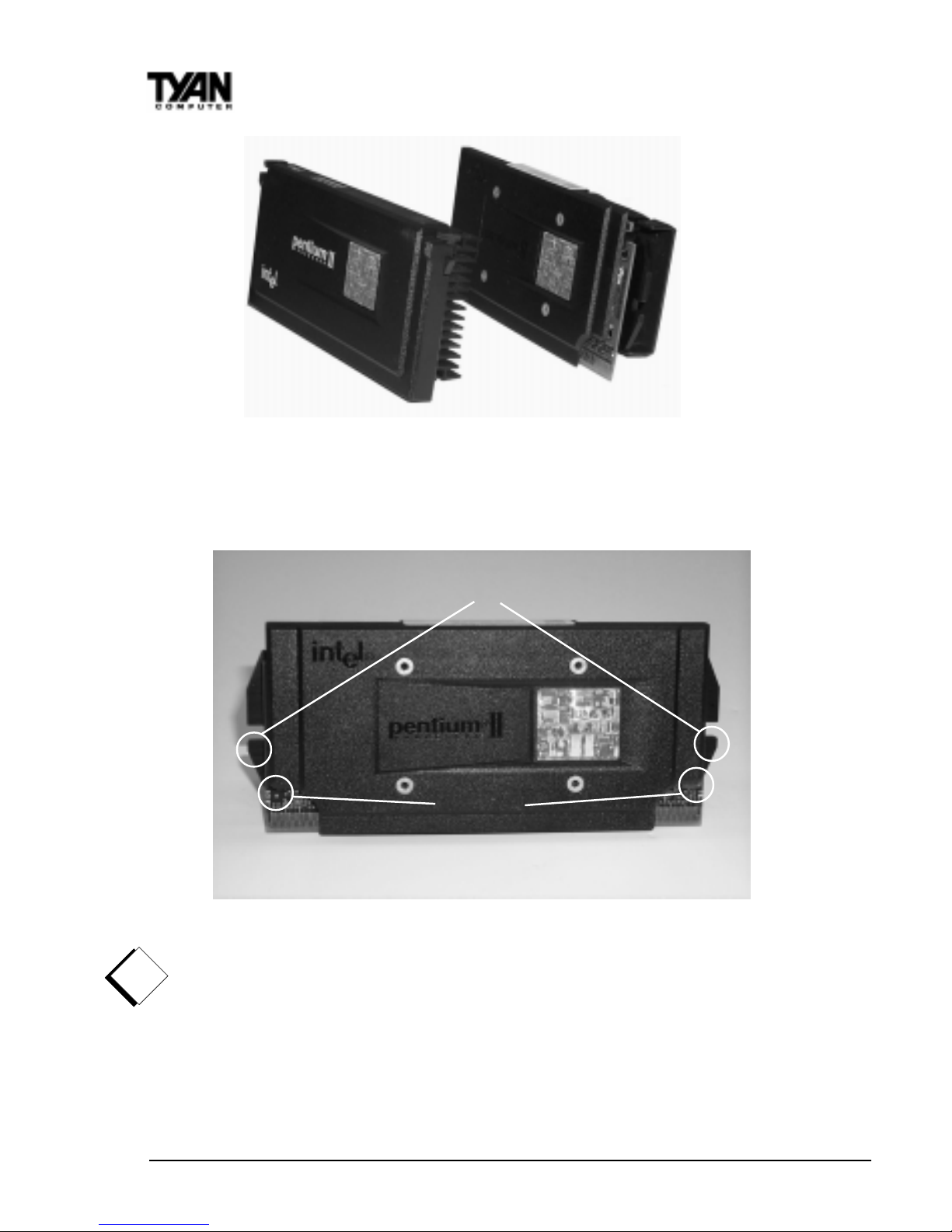
Installing SECC2 CPUs - Option 1
The major physical difference between regular Pentium IIs and Pentium SECC2 is
the plastic CPU enclosure. As Figure 2-12 indicates, the plastic CPU enclosure
covers the entire CPU card of regular Pentium IIs. On the other hand, the plastic
CPU enclosure covers only the side faces of the SECC2 Pentium II / III card.
Due to the physical differences in the SECC2 CPU, installing the retention
modules requires a different technique than the ones previously discussed.
INSTALL
http://www.tyan.com
26
On both sides of the SECC2 CPU reside the lower tabs of the aluminum heat
sink and the bottom corners of the plastic CPU enclosure (see Figure 2-13).
These tabs and corners should fit into the retention braces.
Warning: DO NOT first screw the retention braces onto the motherboard by
themselves. If you do, you will have difficulties inserting the CPU into the
retention braces and CPU slot.
Chapter 2
Board Installation
!
important!
Slot1 CPU SECC2 - Slot1 CPU
Figure 2-12
Lower Tabs
Enclosure
Corners
Figure 2-13
S2257 Thunder 2400
27
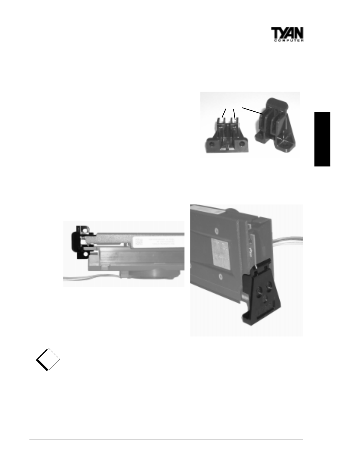
One type of retention module for securing the SECC2 CPU consist of two small
components that resemble bookends. (See Figure 2-14 ) This specific type of
retention may or may not be included in your motherboard package.
The first installation step is to set the
retention braces properly against the sides Slits
of the CPU. The lower tabs of the
aluminum heat sink and the bottom
corners of the plastic enclosure should
loosely fit within the two slits of the braces.
Figure 2-14
Figures 2-15 below show a top view and side view of a retention brace
positioned against one side of the SECC2 CPU.
Top View
Side View
Figure 2-15
When both braces are properly positioned, press both braces against the sides
of the CPU and carefully lift them over the CPU slot on the motherboard.
Warning - Because the braces are loosely held against the CPU, they can
easily fall off. You must hold both braces against the CPU while lifting all
three components above the motherboard. (See Figure 2-16 on the following
page.)
INSTALL
!
important!
http://www.tyan.com
28
Figure 2-16
Be sure to line up the holes of the retention brace with the screws protruding
from the motherboard. At the same time, make sure the CPU is lined up with
the CPU slot. Lower the three components onto the motherboard. The screws
on the motherboard should fit through the holes of the retention braces and
the CPU should fit into the slot. Secure the retention braces with the nuts
provided in the package. The end result should look like Figure 2-17.
Figure 2-17
When removing the CPU, unscrew the nuts on the retention braces and
remove all three components at once. This may require careful firm tugs to pull
the CPU out of its slot.
Chapter 2
Board Installation
S2257 Thunder 2400
29
INSTALL
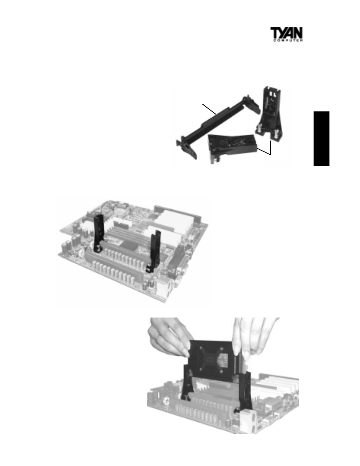
Installing SECC2 CPUs - Option 2
Another method to secure an
SECC2 CPU is by using the
Universal Retention Module
(included in package). The
universal retention module is
designed to accommodate most
versions of the Pentium II / III
CPUs. Included in this solution is
an overhead clip to lock the CPU
into its slot along with the side
universal braces. See Figure 2-18
(right) for the universal retention
module components.
To install the CPU, place the
two side braces at the ends
of the CPU slot (see Figure 219 left). The screws on the
motherboard should fit
through the holes of the
retention braces. Tighten
and secure both braces using
a screw driver.
Next, carefully insert the
CPU between the braces
and onto the CPU slot
(see Figure 2-20). Make
sure the CPU fan faces
towards the center of the
motherboard.
Figure 2-19
Figure 2-20
Figure 2-18
Top Clip
Side Braces
http://www.tyan.com
30
Chapter 2
Board Installation
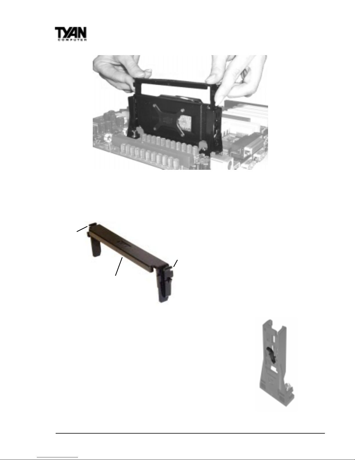
When the CPU is secured onto the slot, take the overhead clip and insert the
ends of the clip over the top of the side braces (See Figure 2-21 above). You
will hear a click when the overhead clip is fitted securely into the side braces.
Make sure the lowered lip of the
overhead clip is oriented away
from the CPU fan (see Figure 2-22
left).
Removing CPU - Removal of the CPU is basically the
reverse order of the installation steps. First remove the
overhead clip. You need to push BOTH side tabs (see Figure
2-22 above) inwards in order to unlock it from the side braces.
After removing the overhead clip, you need to release the
CPU from the braces one side at a time. Press the center
release tab of one of the side braces (see Figure 2-23 right)
while gently pulling that side of the CPU out of its slot.
Repeat the procedure for the other side brace. When both
ends of the CPU is loose from the side braces and the slot,
you will be able to remove it from the motherboard.
Figure 2-21
Ta b
Ta b
Lowered lip
Figure 2-22
Figure 2-23
 Loading...