

TYAN S1836 THUNDER 100 User Manual

Tyan S1836
Thunder 100
Motherboard User’s Manual
Revision 2.30
Copyright © Tyan Computer Corporation, 1998. All rights reserved. No part of this
manual may be reproduced or translated without prior written consent from Tyan
Computer Corp.
All registered and unregistered trademarks and company names contained in this
manual are propery of their respective companies including, but not limited to the
following.
AMIBIOS is a trademark of American Megatrend Incorporated.
Windows is a trademark of Microsoft Corporation.
IBM, PC, AT, PS/2 are trademarks of IBM Corporation.
INTEL, Pentium II, Celeron are trademarks of Intel Corporation.
S1836 Thunder 100 is a trademark of TYAN Computer Corporation.
Information contained in this publication has been carefully checked for accuracy and
reliability . In no event will Tyan Computer be held liable for any direct or indirect,
incidental or consequential damage, loss of use, loss of data, or other malady resulting
from errors or inaccuracies of information contained in this manual. The information
contained in this document is subject to change without notice.
PRINTED IN USA

Table of Contents
1. Introduction....................................................................... 4
Overview............................................................................................... 4
Icons..................................................................................................... 5
Hardware Specifications/Features....................................................6
Software Specifications......................................................................8
T echnical Support...............................................................................8
Returning Merchandise for Service................................................. 9
2. Board Installation..............................................................11
Unpacking............................................................................................11
Installation........................................................................................... 11
Setting Jumpers...................................................................................2 4
3. Onboard Resource Settings.............................................. 2 5
Quick Reference for Jumpers.............................................................2 5
Map of Motherboard Jumpers..........................................................2 6
Hardware CMOS & Password Reset................................................2 8
Soft Power Connector .........................................................................31
Speaker Connector Installation.........................................................3 1
Hardware Reset Switch Connector Installation..............................3 1
W avetable Upgrade............................................................................3 1
External SMI.........................................................................................3 2
Chassis Intrusion Alarm Connector ................................................. 3 2
Audio Connectors.............................................................................. 3 2
CMOS R TC...........................................................................................33
Flash EEPROM....................................................................................3 3
RAM Installation................................................................................ 3 3
Cache Memory .....................................................................................34
Intel Ethernet Setup and Use............................................................ 3 5
Creative Labs Sound Drivers Installation Note..............................4 9
Frequently Asked Questions............................................................ 5 1
4. BIOS Configuration........................................................... 55
Main Setup...........................................................................................5 6
Advanced CMOS Setup.................................................................... 6 1
Chipset Setup...................................................................................... 6 6
Power Management Setup.................................................................7 2
Plug and Play Setup............................................................................7 6
Peripheral Setup.................................................................................. 8 1
Supervisor and User Security ............................................................8 4

Language Utility .................................................................................. 8 5
Flash Writer Utility ..............................................................................8 5
5. System Resources............................................................. 8 7
Beep Codes..........................................................................................8 7
Troubleshooting System Problems..................................................8 8
Displayed Error Messages................................................................ 8 9
Appendix 1 - CPU Retention Module Options............................................... 91
Appendix 2 - Glossary .......................................................................................93
http://www.tyan.com
4
Chapter 1
Introduction
Overview
The Thunder 100 family is a quality , high performance motherboard designed
for Intel Pentium II microprocessors. This motherboard utilizes the Intel 440BX
(S1836DLU, S1836DLUAN) or 440GX (S1836DLUAN-GX) AGPsets and can
support CPU speeds of 233MHz through 450MHz, and host bus speeds of
66MHz to 100MHz.
The motherboard, with built-in AGP slot, provides high performance capabilities that are ideal for a wide range of demanding applications such as CAD,
CAM, CAE, desktop publishing, 3D animation, and video production.
This integrated system board achieves high reliability with numerous features
and yet is small enough to be supported in an Extended ATX form factor . Some
of the features included are onboard dual channel PCI PIO, Bus Master IDE
and UltraDMA/33, onboard floppy controller, onboard dual channel SCSI,
RAIDport II, onboard Creative V ibra 16XV sound, onboard Intel Ethernet, and
onboard high speed I/O (Ethernet and Sound controllers on DLUAN models
only).
W ith I/O and drive controller support built onboard, the one AGP slot, six PCI
and one ISA slots (one shared, seven usable) are free for numerous add-on
expansion cards.
chapter 1
Introduction
S1836 Thunder 100
5
INTRO
Remember to take a look at TY AN Computer’ s web site located at
http://www .tyan.com. There you can find information on all of TYAN’ s
products along with F AQs, distributors list, drivers, and BIOS setting explana-
tions.
Icons
In order to help you navigate this manual and set up your system, we have
added several icons to our format.
This icon alerts you to particularly important details regarding
the setup or maintenance of your system. This icon often
appears next to information that may keep you from damaging
your board or system. While we will often point out the most
vital paragraphs in a chapter, you should always read every word in the text.
Failing to do so can lead to exasperation and expense.
Wherever possible, we have included step-by-step instructions
for setting up your system, which are indicated by this icon.
However, it is in your best interest to read an entire section (and
perhaps the entire manual) before you begin to fiddle with your motherboard.
While we have alerted you to potential dangers in several places
in the manual with this icon, these warnings should not be
regarded as the whole of your safety regimen. Never forget that
computers are electrical devices, and are capable of delivering a shock. Prevent
damage to yourself and to your board: always ensure that your system is
turned off and unplugged whenever you are working with it, and that you are
equipped with a static safety device.
!
important!
procedure
1.
2.
3.
warning

http://www.tyan.com
6
Chapter 1
Introduction
Hardware Specifications/Features
Processor Information · Two SEC slots (Slot One type)
· 66MHz to 100MHz bus support
· Pentium II 233-600MHz
· Supports Celeron CPUs in single
mode
Chipset Information · Intel 440GX AGPset (S1836DLUAN-GX)
· Intel 440BX AGPset (S1836DLU/DLUAN)
· Intel PIIX4e controller
· SMC 932FR Super I/O chipset
· DEC 21152-AB PCI Bridge
Voltage and Power · ATX power supply connector
Information · +12V power source for DC fan onboard
· 3.3V DRAM support
· Utilizes GTL+ bus to reduce power
consumption and EMI
Main Memory · Up to 2048MB* onboard (for GX model)
· Up to 1024MB onboard (for BX models)
· Four 168-pin DIMM sockets
· Supports 100MHz SDRAM with
SPD, and SDRAM+ECC
· Supports 66MHz SDRAM with SPD
with 66MHz CPU clock only
System Management
··
··
· National LM79 and LM75 ASICs with
onboard alarm for monitoring temperature,
supply voltages, and fan speed
··
··
· Intel LANDesk Client Manager
software
··
··
· Chassis intrusion detection capable
* See TYAN website for list of compatible memory modules.

S1836 Thunder 100
7
INTRO
Expansion Slots · One 32-bit AGP slot
· Six 32-bit PCI Bus Master slots
· One 16-bit ISA slot
· One shared, seven usable
Physical Dimensions · Extended ATX design
· 13 inches x 12 inches
· IO shield compatible with Intel
Providence (included)
BIOS Information · AMI Plug and Play flash BIOS
· Deep Green, Ener gy Star, ACPI, Year 2000,
and PC98 compliant (the Adaptec AIC-7895
SCSI chip is NOT PC98 compliant)
· Yellow LED for sleep mode
Disk Drive & System I/O · T wo PCI bus mastering EIDE
channels
· Supports EIDE CD-ROMs
· PIO Mode 3 & 4 (up to 17MB/sec DTR)
· UltraDMA/33 bus mastering mode
(up to 33MB/sec DTR)
· Support for two floppy drives (Mode
3 and 2.88MB supported)
· T wo serial ports (16550 UAR T s)
· One ECP/EPP parallel port
· One IR (InfraRed) I/O interface port
· T wo USB rev 1.2 ports
· One PS/2 mouse port
· One PS/2 keyboard port
· Wake-on LAN header (requires ATX
2.01 power supply)
Onboard UltraWide SCSI · Adaptec AIC-7895 dual channel UltraW ide
SCSI
· T wo 68-pin high density UltraW ide SCSI
ports
· One 50-pin SCSI-2 port
· Adaptec Ultra SCSI BIOS

http://www.tyan.com
8
Chapter 1
Introduction
· RAID 0 and 1 support using optional
Adaptec ARO-1130CA PCI card
(RAIDport II)
Creative Labs Sound · V ibra 16XV Midi audio chip
(S1836DLUAN models only) · ATX Joystick, Audio in, Speaker ,
Microphone connectors
Onboard Ethernet · Intel 82558 10/100 Ethernet
(S1836DLUAN models only) onboard
· Full Wake-on functionality (see
power supply requirements above)
· One RJ-45 ATX connector
Software Specifications
OS ·Operates with MS-DOS, Windows
3.x, Windows for WorkGroup 3.x,
W indows 95, Windows 98, W indows
NT , OS/2, Novell Netware, Solaris,
and SCO Unix
T echnical Support
If a problem arises with your system, you should turn to your dealer for help
first. Your system has most likely been configured by them, and they should
have the best idea of what hardware and software your system contains.
Hence, they should be of the most assistance. Further, if you purchased your
system from a dealer near to you, you can actually bring your system in to
them to have it serviced, instead of attempting to do so yourself (which can
have expensive consequences).
If your dealer is unable to assist you,
try our web page, http:// www .tyan.com
user newsgroup, alt.comp.periphs.mainboard.tyan

S1836 Thunder 100
9
technical support phone line, (510) 440-8808
or e-mail address techsupport@tyan.com
Returning Merchandise for Service
During the warranty period, contact your distributor or system vendor FIRST
for any product problems. This warranty only covers normal customer use and
does not cover damages incurred during shipping or failure due to the
alteration, misuse, abuse, or improper maintenance of products.
For Resellers Only:
A receipt or copy of your invoice marked with the date of purchase is required
before any warranty service can be rendered. You can obtain service by calling
the manufacturer for a Return Merchandise Authorization (RMA) number . The
RMA number should be prominently displayed on the outside of the shipping
carton and the package should be mailed prepaid, or hand-carried to the
manufacturer. TYAN will pay to have the board shipped back to you.
INTRO

http://www.tyan.com
10
This page is intentionally left blank.
S1836 Thunder 100
11
chapter 2
Board Installation
Unpacking
The motherboard package should contain the following:
· S1836DLU, S1836DLUAN or S1836DLUAN-GX motherboard
· One 40-pin IDE and 34-pin floppy cable pack
· One 9-pin Com port cable
· User’s manual
· One Ultra Wide SCSI cable
· One regular SCSI cable
· T wo retention modules
· One A TX I/O Shield
· One System Management & Driver CD; includes complete drivers for
LAN and audio controllers and manual and installation instructions for
Creative Vibra 16XV.
Installation
You are now ready to install your motherboard. The mounting hole pattern of
the Thunder 100 matches the ATX system board specifications. Your chassis
http://www.tyan.com
12
should be that of a standard ATX motherboard form factor .
How to install our products right...the first time.
What’s the first thing I should do?
The first thing you should do is read this user’s manual. It contains important
information which will make configuration and setup much easier.
The next step is to properly ground yourself. First, unplug the power from your
computer case and then touch the metal casing of the power supply or any
metal part on the computer case. This will discharge any electricity from your
body. Take the motherboard out of the cardboard box and static bag, holding it
by its edges, and place it on a grounded anti-static surface, component side
up. Inspect the board for damage.
DO NOT APPL Y POWER TO THE BOARD IF IT HAS BEEN DAMAGED!
Press down on any of the socket ICs if it appears that they are not properly
seated (the board should still be on an anti-static mat). Do not touch the
bottom of the board. Remember, don’ t take any electronic device out of its
protective bag until you are ready to install it into the computer case. If you
don’t ground yourself, you risk zapping the motherboard or adapter card.
Subsequent problems may not arise immediately because electrostatic discharge damage, unlike physical damage, causes the device to fail over time.
Install the motherboard into your case.
Follow the instructions provided by the case manufacturer for proper installation guidelines. TYAN recommends that you use only one screw to hold down
the motherboard. The rest of the mounting holes should be used for the plastic
standoffs. If your case does not have a hole for a standoff, simply cut off the
bottom of the plastic standoff so that the flat portion rests on the metal. The
adapter cards and the screws holding them down will keep your board flat. The
fastening screw should not short any of the traces on the motherboard. Make
certain that you do not overtighten the screw, as it will damage the motherboard and possibly break internal traces in the surrounding area. The hole you
should use is located at the top-center of the board where the adapter cards
are fastened to the case.
procedure
1.
2.
3.
!
important!
Chapter 2
Board Installation

S1836 Thunder 100
13
Plug in the power connector as shown.
The photos below show the ATX power connector before (Figure 1) and after
(Figure 2) it has been plugged in.
The plastic clip on the power connector should lock over the plastic tab on the
onboard connector. You shouldn’t be able to plug the power connector in any
other way but just to be safe, make sure it looks like Figure 2 above. Make
absolutely certain that you do not miss any pins because, if you do, you will
void your warranty and cause damage to yourself or your motherboard when
you turn the system on. After connecting the power, make sure the connector
is seated firmly into its socket so it will not become loose or fall off when the
computer is jostled or moved. Note: T yan recommends using an ATX power
supply that conforms to industry standard revision 2.01.
Figure 1
Figure 2
warning
INSTALL
http://www.tyan.com
14
Chapter 2
Board Installation
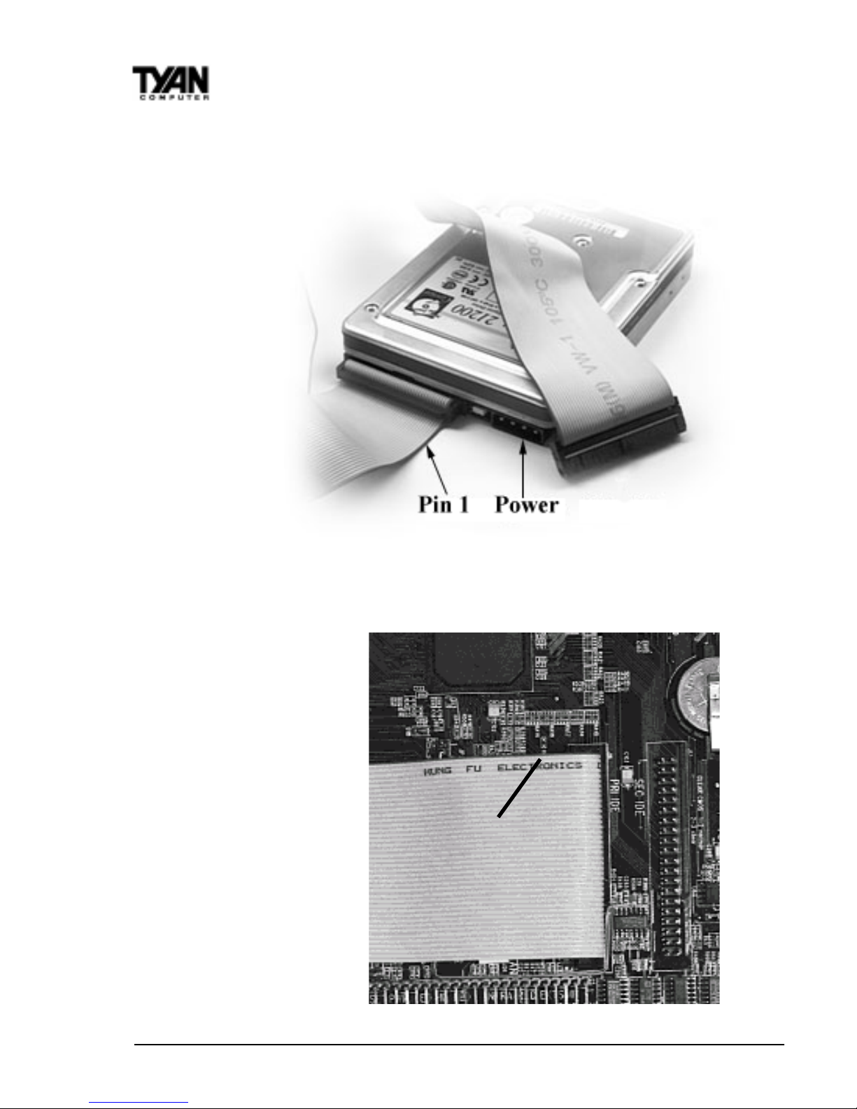
Next, connect your IDE cables (if you’re using IDE hard drives).
On all TYAN motherboards, the colored stripe on the cable always faces
towards the rear of the case (towards the ATX connectors).
In Figure 3 you can see
how the IDE cables should
look when they are
connected to your hard
drive. Notice how Pin 1
(denoted by a red stripe) is
connected so that it is next
to the power connector of
the drive. In most cases,
this is the proper way of
connecting your IDE cable
to the hard drive. Figure 4
shows the IDE cable
properly connected to the
motherboard.
Contact your hard disk
drive manufacturer or
documentation for more
Figure 3
Figure 4
Pin 1
S1836 Thunder 100
15
information.
Some symptoms of incorrectly installed HDDs are:
• Hard disk drives are not auto-detected: may be a Master/Slave
problem or a bad IDE cable. Contact your vendor .
• Hard Disk Drive Fail message at bootup: may be a bad cable or
lack of power going to the drive.
• No video or beeps on bootup: usually means the cable is on
backwards.
• Hard drive lights are constantly on: bad IDE cable or defective
drives/motherboard. Try another HDD.
• Hard drives do not power up: check power cables and cabling.
May also be a bad power supply or IDE drive.
Now that you have installed your IDE drives, your floppies are next.
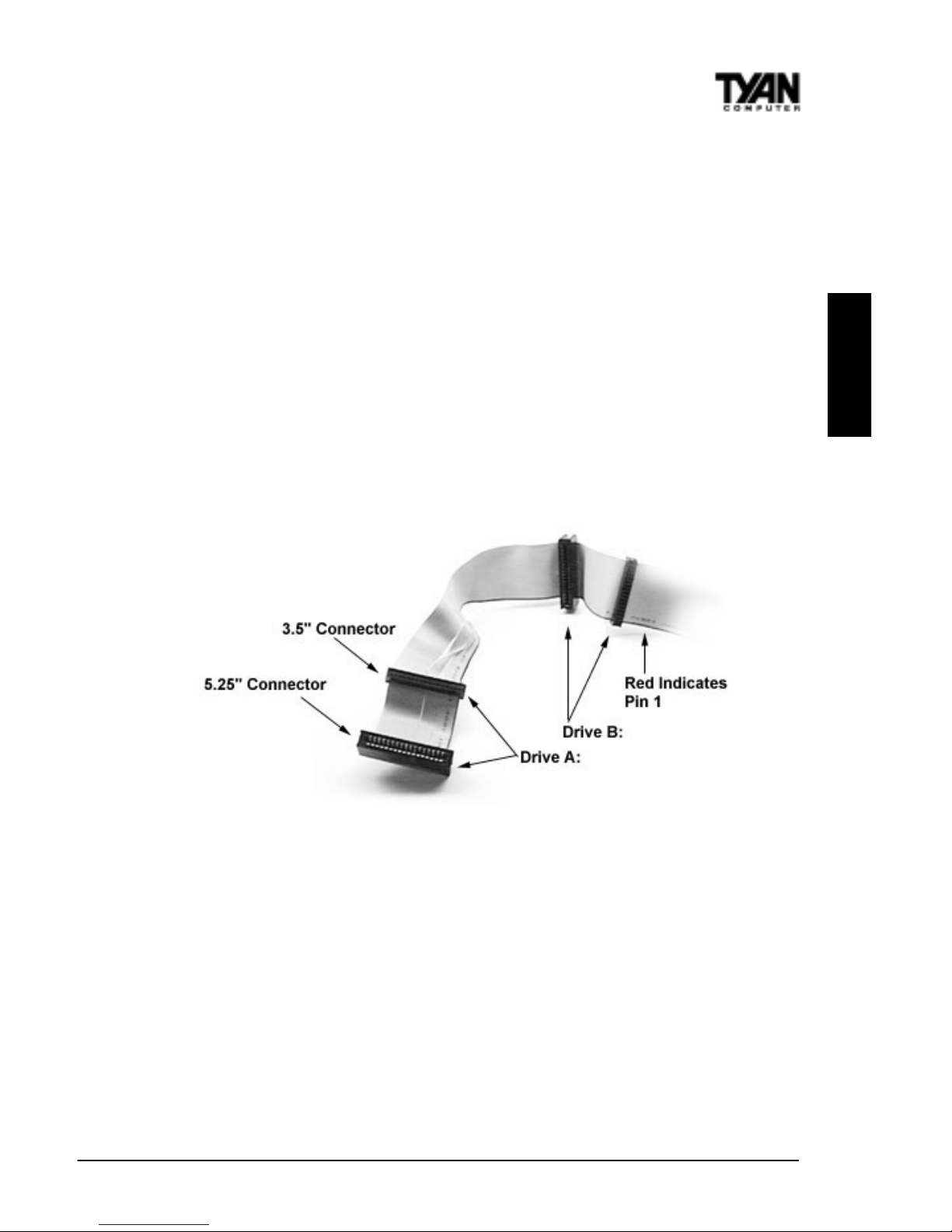
Pin 1 on the floppy cable is usually denoted by a red or colored stripe down
one side of the cable (see Figure 5 above). Most of the current floppy drives
on the market require that the colored stripe be positioned so that it is right
next to the power connector . In most cases, there will be a key pin on the cable
which will force you to connect the cable properly .
Drive A: is usually attached to the end of the cable with the twist in it. Drive B:
is usually connected to the middle of the cable. Refer to your installation
instructions or call your dealer if you are unsure about attaching floppy drives.
Refer to Figure 5 for a detailed anatomy of the floppy cable. Remember, you
can only have 2 floppy drives connected at any given time.
Figure 5
INSTALL
http://www.tyan.com
16
Chapter 2
Board Installation
On all TYAN motherboards, the colored stripe on the cable always faces
towards the rear of the case (towards the ATX connectors), as with the IDE
cables. Please refer to your documentation for proper installation, or see Figure
4 on page 14.
Some symptoms of incorrectly installed floppies are:
• Floppy drives are not detected: usually caused by faulty cables, backward
cables, or a bad floppy or motherboard. Try another single floppy drive to
verify the problem or try another cable. Also, check to see if the onboard
floppy is enabled in the BIOS.
• Floppy Drive Fail message at bootup: the cable, floppy , or motherboard
may be faulty . T ry another cable or floppy drive to verify.
• Light on the floppy is on constantly: a dead give-away that the cable is on
backwards. Reverse the cable at the motherboard end and try again.
Next are the Com and Printer ports.
W arning: When plugging in your keyboard and mouse, or when plugging
anything into a serial or Com port, make sure that the power is off. Connecting
these devices and ports while the power is on is called “hot plugging,” and
may damage your system.
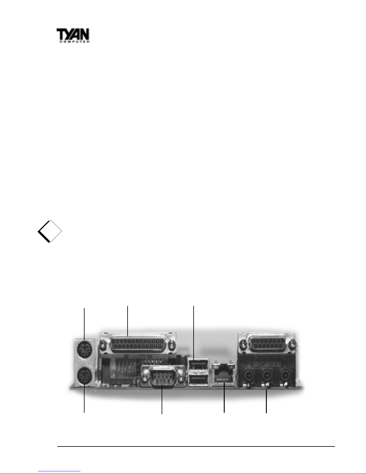
Figure 6 below shows the ATX double row connectors on this board. The Com
and Printer ports, as well as the other ports, are labeled.
!
important!
Figure 6
PS/2 Mouse LP1 USB
PS/2 Keyboard Com1 LAN* Sound*
S1836 Thunder 100
17
(* S1836DLUAN and S1836DLUAN-GX only)
Note: Only TYAN cables will work on this motherboard. If you are using an
existing case with old cables, your system will not function properly . Use only
TYAN-approved cables.
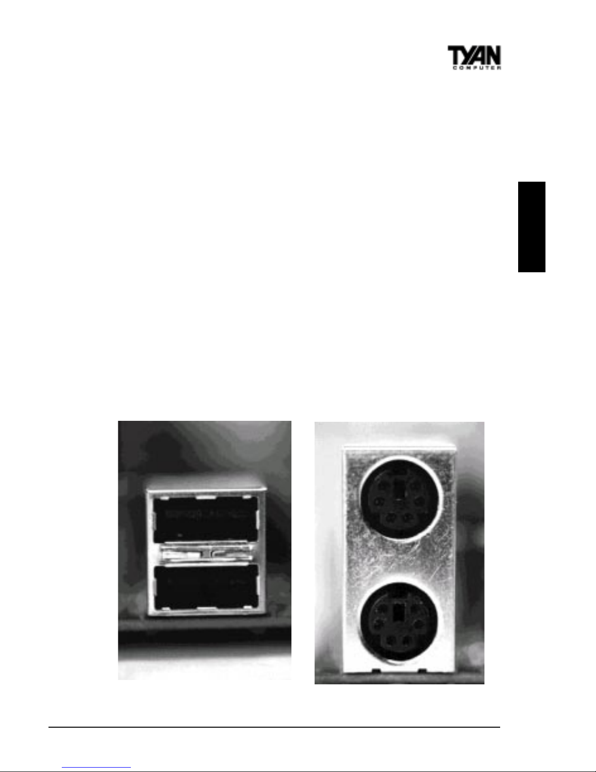
Connecting the USB and PS/2 ports.
This board includes ports for USB, PS/2 mouse, and PS/2 keyboard devices.
The location of these ports is shown in Figure 6 above. Note that, for this
board, the PS/2 mouse port is the upper PS/2 port, and the PS/2 keyboard port
is the lower PS/2 port.
The PS/2 connectors are probably quite familiar to you. The USB connectors,
however, may be foreign. The USB (Universal Serial Bus) is a versatile port.
This one port type can function as a serial, parallel, mouse, keyboard, or
joystick port. It is fast enough to support video transfer, and is capable of
supporting up to 127 daisy-chained peripheral devices. Close-ups of the USB
connector, as well as of the USB and PS/2 ports, are on the following page.
Figure 7 shows the USB ports and Figure 8 the PS/2 ports.
INSTALL
Figure 7 Figure 8

http://www.tyan.com
18
Chapter 2
Board Installation
Installing your add-in cards is relatively simple but...
there are a few rules you need to follow when plugging in a card. In order to
assure proper operation and a quick installation, adhere to these guidelines:
• If you are going to install a PCI-Bus interface card on your system,
be aware that any one of the two PCI slots can support a Master
or Slave device.
• NEVER force a card into a slot. If it doesn’t fit, look at the socket
on the computer to make sure there are no wires or other
obstructions to the slot.
• NEVER plug an ISA card into a PCI slot or a PCI card in an ISA
slot. You will void your warranty and damage your system board if
you do this.
• When plugging the card in, especially when installing long cards,
try to push the entire card in at one time. Don’t force one end of
the card into the socket first and then the other. This will create a
rocking motion between the card and the slot and it will damage the
pins within the socket.
• Make sure that the cards are seated securely into the slots.
• Before turning on the system, make sure no cards are touching
each other or are shorting.
If you follow these basic guidelines, there shouldn’t be any problems with
installation. However, if you do encounter any problems, have a qualified
professional install your cards for you or contact your card manufacturer .
Remember, always read the manuals and installation notes that come with the
adapter cards. They contain important information which will help you install
the components right, the first time.
Next, you need to install your memory.
Since TYAN boards are manufactured with performance in mind, you should
use add-in components that match. Some DIMM modules may seem to be
high quality because of name or feel but that does not guarantee real-world
usability . Some cheaper or OEM memory may have brand-name components,
but they may contain inferior or substandard parts which do not meet the
critical tolerances our products require. Because of this, your memory may not
work correctly in a TY AN board though it may work well in a competitor’ s
board. This is because many of our competitors do not adhere to the strict
tolerances required for high performance. If you buy a TYAN board, you are
getting the best system available. To make installation easy and trouble free,
!
important!
S1836 Thunder 100
19
get high quality parts. Some brands we recommend are Advantage Memory ,
Corsair Microsystems, Millenium, Kingston Memory , QesT ec Incorporated,
Unigen, Micron Technology, and Crucial Technology. These DIMMs have
proven to be very stable on our boards and perform extremely well.
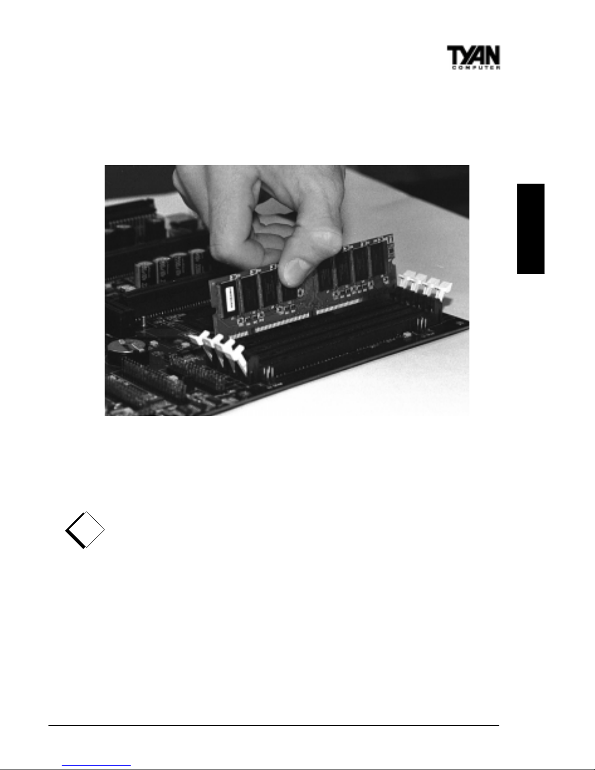
Figure 9
To install your DIMMs, line your module up so that the pins fit into the slot.
There is only one way that your DIMM can fit properly. Make sure that the
short row of pins is lined up with the short gap in the DIMM slot. Figure 9
shows how to sit the DIMM into its slot. To insert the DIMM, push down
vertically on the module with even force, as shown in the photo. Do not shove
one end in first; doing so will bend the DIMM pins.
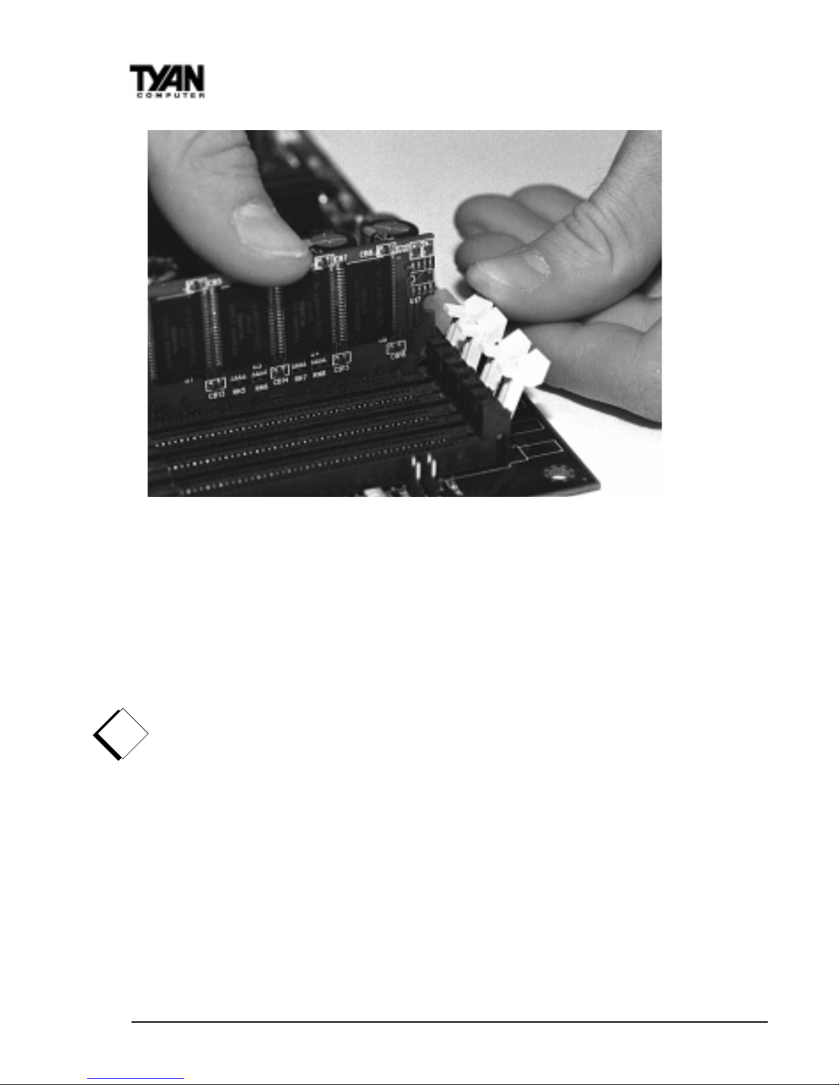
To lock the DIMM into place, push the plastic clips on either end of the slot
onto the notches in the ends of the DIMM (see Figure 10 on the following
page). T o remove your DIMM, simply pull the clips back, and pull up on the
module.
INSTALL
!
important!
http://www.tyan.com
20
Chapter 2
Board Installation
Figure 10
Place the DIMMs in an anti-static bag as soon as you remove them to avoid
static damage.
Finally, install your CPU.
Pentium II processors (233 through 450MHz) can be used on the Thunder 100.
Please refer to pages 28-30 for the correct CPU jumper settings for your board.
Remember:
· The CPU is a sensitive electronic component and it can easily be damaged
by static electricity . Do not touch the CPU pins with your fingers.
· Before the CPU is installed, the motherboard must be placed on a
flat surface. Y ou should be able to insert the CPU with minimal, but
firm, pressure. Do not press down hard on the CPU.
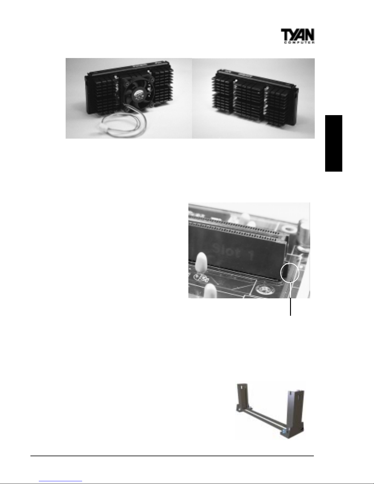
Currently , two types of cooling mechanisms are produced for Pentium II
processors: active (figure 11) and passive (figure 12). These two types of
cooling methods essentially perform the same function. The active cooler is
equipped with a cooling fan and heat sink, while the passive cooler is simply a
larger heat sink with no fan. The type of cooler used has no effect on performance, and both types can be installed in the Pentium II slot on the Thunder
100 board.
!
important!
S1836 Thunder 100
21
Figure 1 1 Figure 12
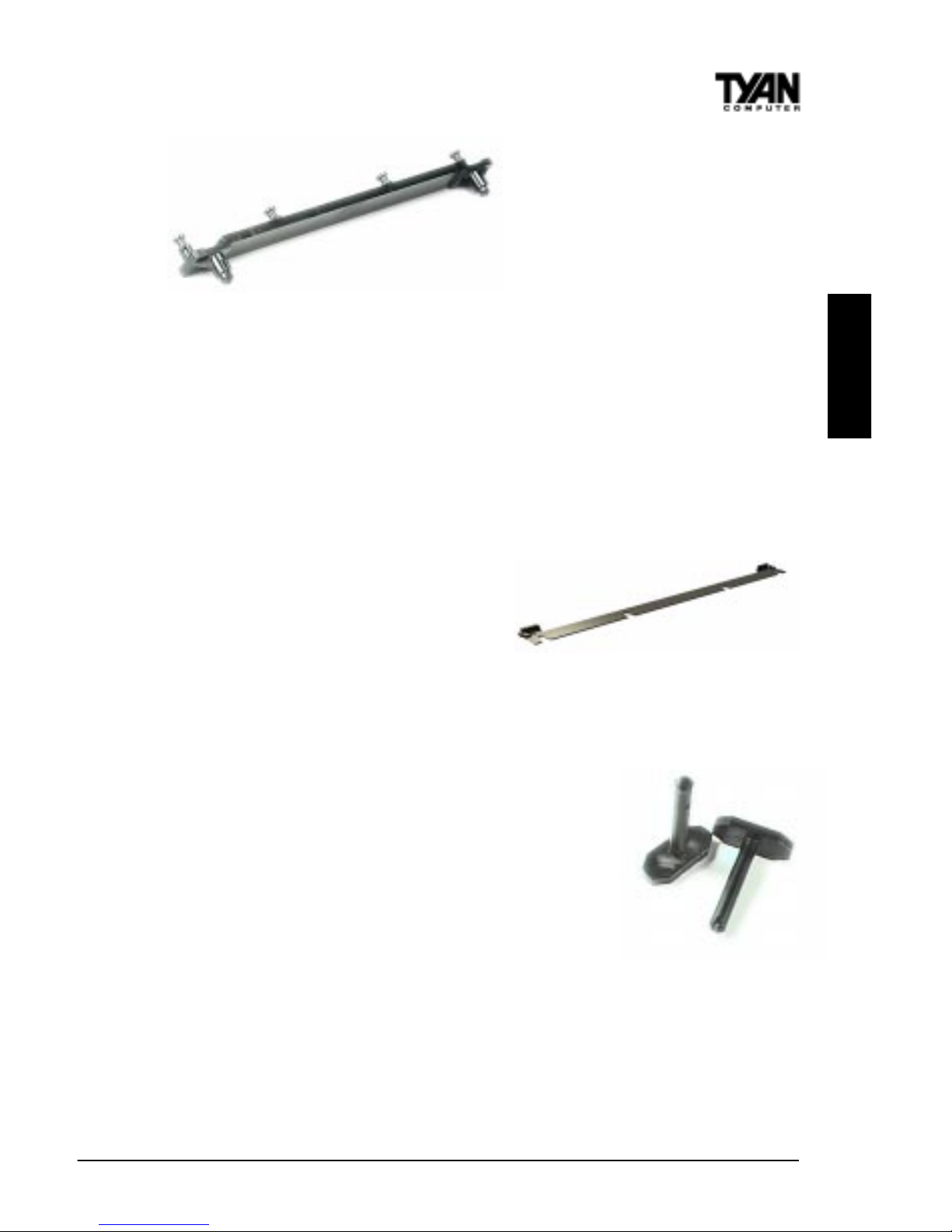
Installing CPU Retention Modules
Installation of a Pentium II processor requires a CPU retention module, which
is first secured onto the motherboard. Tyan offers a variety of retention
mechanisms for the different CPU
types. See Appendix 1 for details.
To attach the retention module,
place the motherboard on a flat
surface. Locate the key pin on one
end of the Pentium II slot on the
board. Then carefully line up the
key notch on the retention module
with the key pin on the Pentium II
slot (the key pin on the Pentium II
slot indicates the correct
orientation of the CPU).
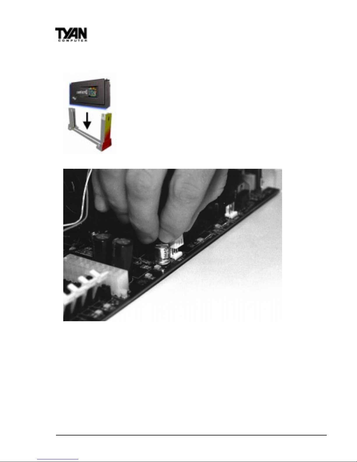
Drop the retention module (Figure
14 on the following page) down
over the Pentium II slot so that the retention module sits flat against the
motherboard. Tighten the screws in a clockwise manner to secure the module
to the board. Warning: Do not overtighten the screws as you may damage the
module and/or the motherboard.
Installing the CPU with Active Cooling
When the retention module is securely installed,
you are ready to plug in the CPU. Press down firmly
on the CPU until you hear a “click” (see Figure 15
on the next page). This clicking sound indicates
INSTALL
Figure 14
Figure 13 - Pentium II Slot Connector
and Key Pin
http://www.tyan.com
22
Chapter 2
Board Installation
that the CPU is fully locked into the retention module. If you have an active
cooler, you will also need to connect the CPU’s cooling fan cable to the cooling
fan power connector on the board.
Locate the cooling fan connector (e.g. F AN1) on the motherboard. Plug the CPU’ s cooling fan cable into the cooling
fan connector on the board. There will be a plastic clip assembly similar to that of the ATX power connector that will
force you to connect the fan cable correctly (see Figure 16
below).
Figure 16
Installing the CPU with Passive Cooling
The installation of the CPU with passive cooling differs only slightly from that
of the active. Your passive cooling package should contain one CPU retention
module, one heat sink retention bracket with mounting locks, two mounting
attachments, and one heat sink lock.Install the retention module as explained in
the previous section.
The heat sink mount (Figure 17) has two pins on the bottom and four pins on
the top. Notice that the bottom two pins are of different sizes. The size of the
Figure 15
S1836 Thunder 100
23
pins and the holes in the motherboard will determine the correct
orientation. When the bracket is
correctly installed, the four pins
on top will be right next to the
Pentium II CPU slot.
Insert the heat sink mount into the holes on the motherboard. When the
bracket is properly inserted into the holes on the motherboard, you will hear a
clicking noise.
Align the CPU with the CPU retention module. Make sure the heat sink is lined
up with the heat sink mount bracket. If you put the CPU in the wrong way , you
may damage the CPU, the motherboard, and/or the CPU socket. Slowly press
down on the CPU module until the CPU locks into place. Y ou will hear a
clicking noise when the CPU is locked securely into the module.
The heat sink lock (Figure 18) has four
notches which will correspond to the
four pins on the heat sink mounting
bracket. Gently slide the lock between
the heat sink and the heat sink mounting bracket until both sides of the lock are firmly secured. A clicking sound will
be heard when the lock is securely fastened to the heat sink mounting bracket.
T o remove the lock from the heat sink mounting
bracket, gently press the ends of the locks inward and
pull.
Lock the heat sink mount to the board by inserting
the two mounting locks (Figure 19) into the pins of
the heat sink mounting bracket which are now below
the mainboard. There will be a click when the locks are
securely fastened.
Removing the CPU.
T o remove the CPU, move the locks to the center of the CPU. A click will be
heard when the CPU has been unlocked. Gently pull up on the CPU, taking
care not to bend the motherboard or the CPU retention module.
To remove the lock from the retention module, gently press the ends of the
locks inward and pull.
INSTALL
Figure 19
Figure 17
Figure 18
http://www.tyan.com
24
You are done.
Other than checking the jumper settings and cable connections and putting
the case back on, you are done. Installing a new motherboard may sound
difficult, but by following these directions, you should have a fairly uneventful
time installing our products. If you do encounter problems, your dealer will be
able to help you, or you can consult one of our many technical support
resources (see page 8).
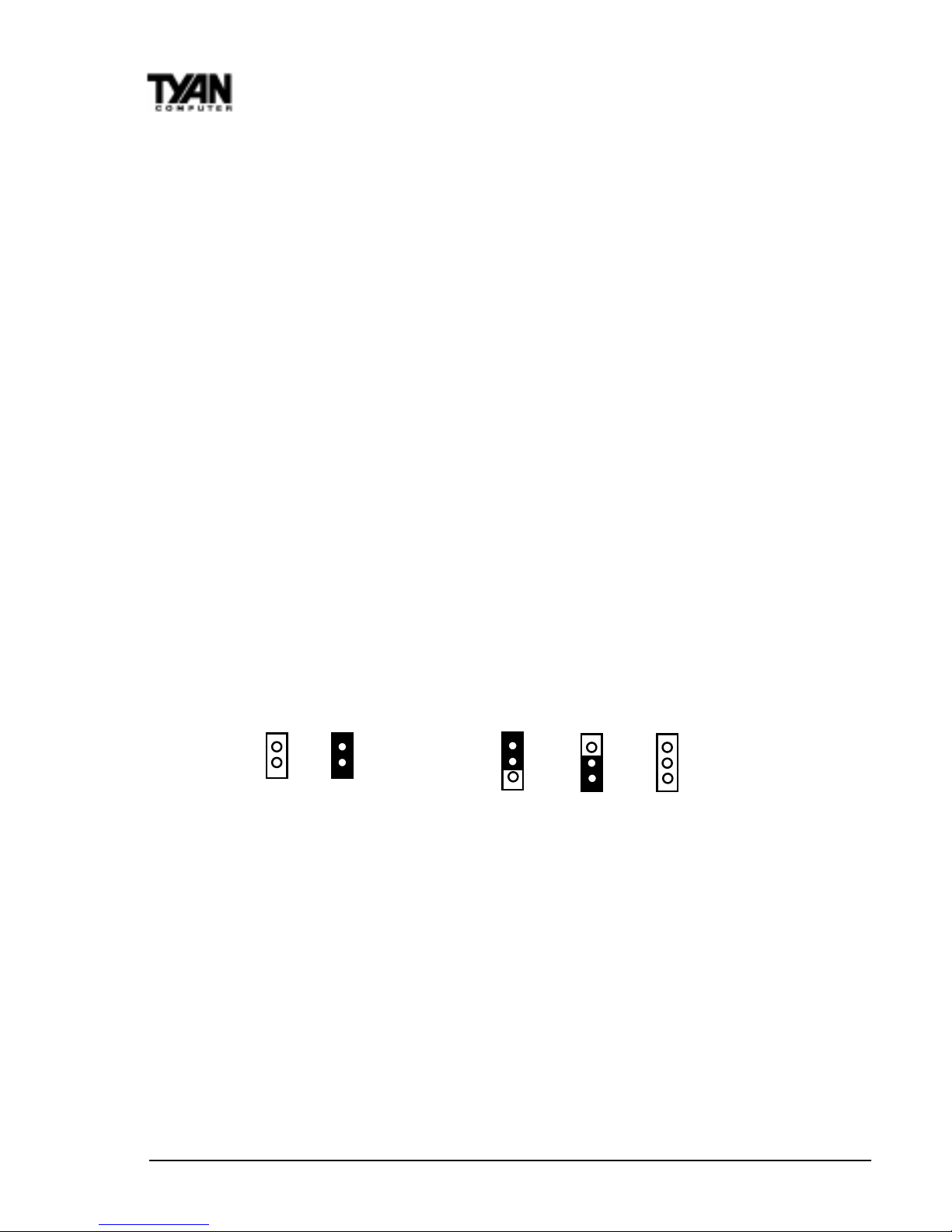
Setting Jumpers
In this manual, the terms “closed” and “on” are used when referring to
jumpers (or jumper pins) that are active; “open” and “off” are used
when referring to jumpers (or jumper pins) that are inactive. Jumpers
and pins are connected by slipping the blue or black plastic jumper
connector overtop of two adjacent jumper pins. The metal rod inside
the plastic shell bridges the gap between the two pins, completing the
circuit. See the drawings below for examples of “on” and “off” pins
and jumpers.
2 pin jumpers
off on
3 (or more) pin jumpers
1-2 2-3 open
1
2
3
1
2
3
1
2
3
Chapter 2
Board Installation

S1836 Thunder 100
25
Quick References for Jumpers
The tables on the following pages will help you set the jumpers for CPU speed,
SCSI settings, and external connector pin assignments, among others. The miniature motherboard maps will help you locate the jumpers on your board. A fullpage map of the motherboard can be found on the next page.
chapter 3
Onboard Resource Settings
http://www.tyan.com
26
Chapter 3
Onboard Resource Settings
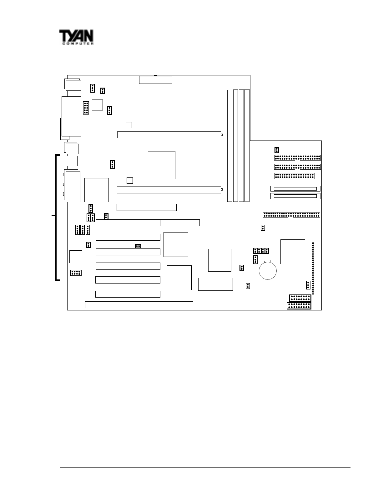
The tiny “1”s next to jumpers of 3 pins or more indicate the position of pin 1 for
that jumper .
** The following components are NOT included in the S1836DLU:
1) Ports - Ethernet / Joystick / Sound
2) Chips - Intel 82558 Ethernet Chip / Creative V ibra 16XV
3) Jumpers - JP16 - 20 and JP31 - 33
Map of Motherboard Jumpers
AGP port
PCI slot 1
PCI slot 2
PCI slot 3
PCI slot 4
PCI slot 5
3 volt
lithium
battery
ISA slot 1
AMIBIOS
Intel
82371EB
chip
PCI slot 6
Primary IDE connector
Secondary IDE connector
Floppy connector
Wide SCSI Channel B
Wide SCSI Channel A
Narrow SCSI Channel A
Adaptec
AIC-7895P
SCSI chip
SMC 932FR
Super I/O
chip
CPU slot 1 (Slot One type)
CPU slot 2 (Slot One type)
DIMM bank 4
Intel
82443BX
or GX chip
DIMM bank 3
DIMM bank 2
DIMM bank 1
RAID port
USB1
Keyboard
USB2
Mouse
COM1
Printer Port
Joystick
Speaker out Line in Mic in
ATX power supply
LM79
JP3
JP25
JP29
J10
JP30
JP17
JP16
JP31
JP22
JP32
JP33
JP19
JP20
JP18
FAN2
FAN1
FAN3
JP26
COM2
J8
JP12
JP11
JP10
JP9
LM75
1
LM75
1
1
1
1
1
1
1
1
11
1
1
Ethernet
port
Intel
82558
Ethernet
chip
digital
21152-AB
chip
Creative
Vibra
16XV
JP46
FAN4
Chassis Fan
1
**
JP45
JP44
S1836 Thunder 100
27
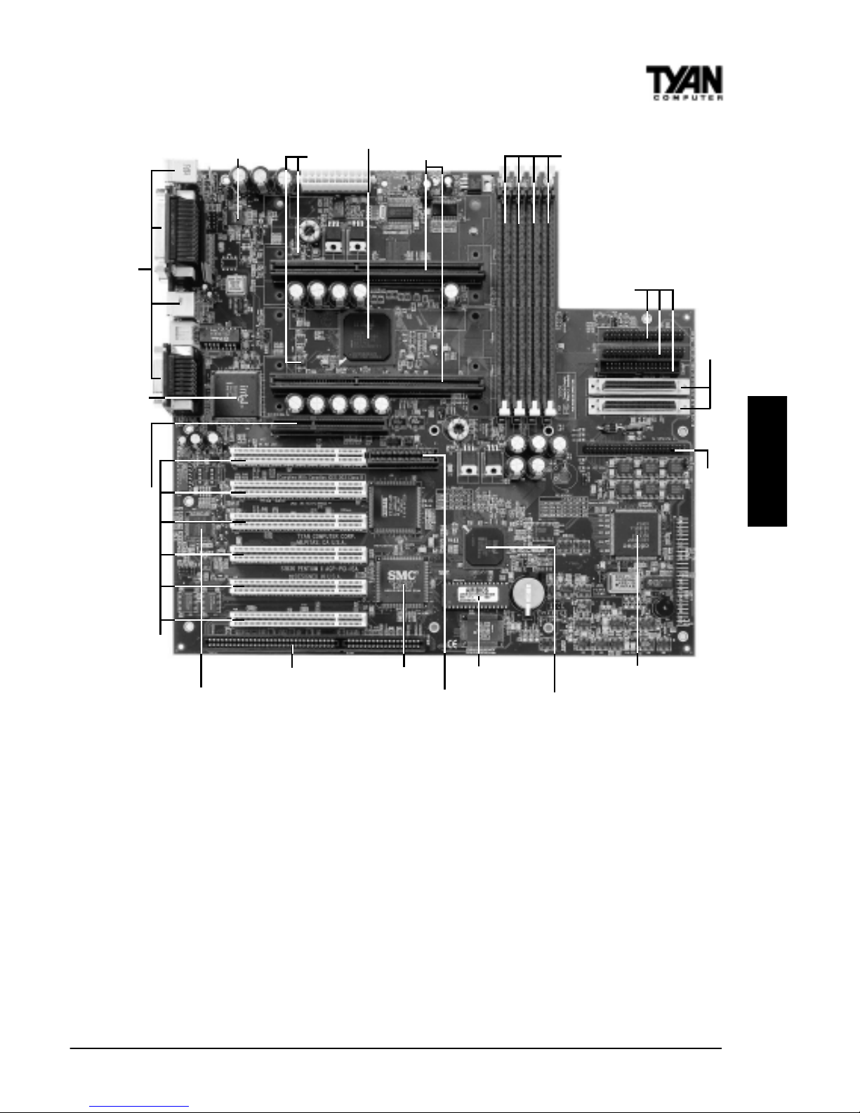
Intel 443BX/GX
4 DIMM slots
2 SEC slots
LM79
2 Wide SCSI channels
1 Narrow SCSI channel
Adaptec AIC-7895
AMIBIOS
1 ISA slot
6 PCI slots
Intel PIIX4e
SMC 932FR
Intel 82558 Ethernet
LM75
AGP port
RAID port
Creative Labs Vibra 16XV
IDE and Floppy
connectors
Double row ATX connectors
ONBOARD
http://www.tyan.com
28
Chapter 3
Onboard Resource Settings
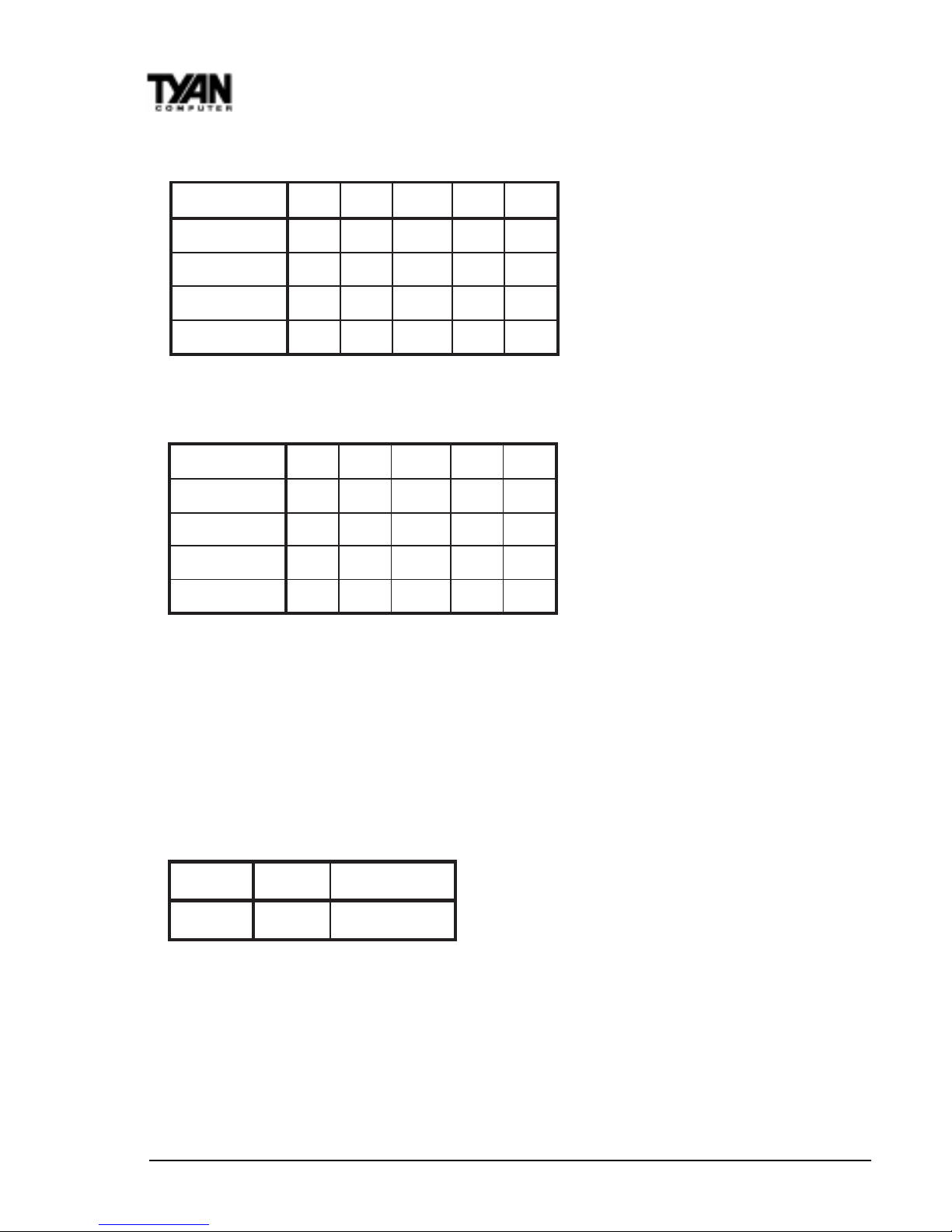
CPU Settings for 66MHz Bus
CPU Settings for 100MHz Bus
*Due to CPU unavailability , this speed has not been tested.
Note on 66/100 MHz bus speeds: You must have a 100MHz processor to run at
a bus speed of 100MHz. If you have a 100MHz processor, do not try and run it
at 66MHz. The bus speed is BIOS selectable. Y our processor will automati-
cally run at the correct bus speed because the BIOS default is Auto.
CMOS Settings
Hardware CMOS & Password Reset
If you have been locked out of your system because you forgot your
password or set the CMOS incorrectly , follow the instructions below.
1. Power off the system
2. Set jumper JP3 to pins 2 and 3 (see previous page for
location of JP3).
deepSkcolCtluM9PJ01PJ11PJ21PJ
zHM053
5.3xNOFFOFFONO
zHM004
4xFFONONONO
zHM054
5.4xFFONOFFONO
zHM005*
5xFFOFFONONO
deepSkcolCtluM9PJ01PJ11PJ21PJ
zHM332
5.3xNOFFOFFONO
zHM662
4xFFONONONO
zHM003
5.4xFFONOFFONO
zHM333
5xFFOFFONONO
tluafeDSOMCteseR
3PJ
2-13-2
S1836 Thunder 100
29
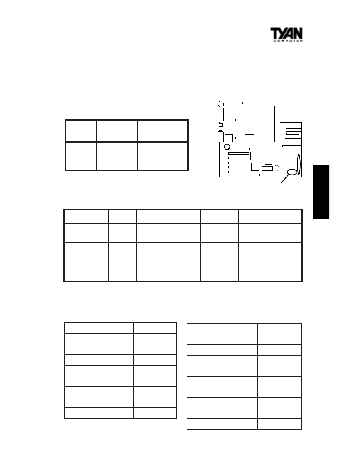
3. Wait for 2 seconds, then return jumper JP3 to pins 1 and 2.
4. Power on the system again.
By following this procedure, you will erase your password and reset the
SCSI IRQ Settings CMOS to the BIOS defaults.
Line Out Sound Settings
J10 External Connector Pin Assignments
ONBOARD
pmaerPhtiw
)tluafed(
pmaerPtuohtiw
23PJ
2-13-2
33PJ
2-13-2
J10
JP32, JP33
sniP2-101-661-3102-8132-2272-42
noitcnuF
rewoP
ffO/nO
RI
rotcennoC
DELDDHDELrewoP
teseR
hctiwS
rekaepS
tnemngissA
rewoP=1
ffO/nO
DNG=2
CCV=6
XRRI=8
DNG=9
XTRI=01
edoM=11
-=51
+=61
DNG=81
+=02
DNG=22
teseR=32
CCV=42
lanretnI=62
rekaepS
-=72
CCV12 DELrewoP
DELDDH34 DELpeelS
dnuorG56 ffO/nOrewoP
teseR78 dnuorG
CCV901hctiwSIMS
evieceRRI1121CCV
dnuorG3141tcennoCoN
timsnarTRI5161CCV
tcennoCoN7181tcennoCoN
#IMSREVRES12KLCBMSMN
DNG34 DNG
niFFO/NO56 ATADBMSNM
KOPL78 KLNUYEK
TUOIMN901V3BSMN
#TESR_PF1121DNG
DNG3141tcennoCoN
ERUCES5161DNG
TNISIHC7181tcennoCoN
tcennoCoN9102DNG
JP45 Pinout JP44 Pinout
2x9 External Connector Proprietary Server Mgmt Connector
(for OEM use only)
JP44
JP45
http://www.tyan.com
30
Chapter 3
Onboard Resource Settings
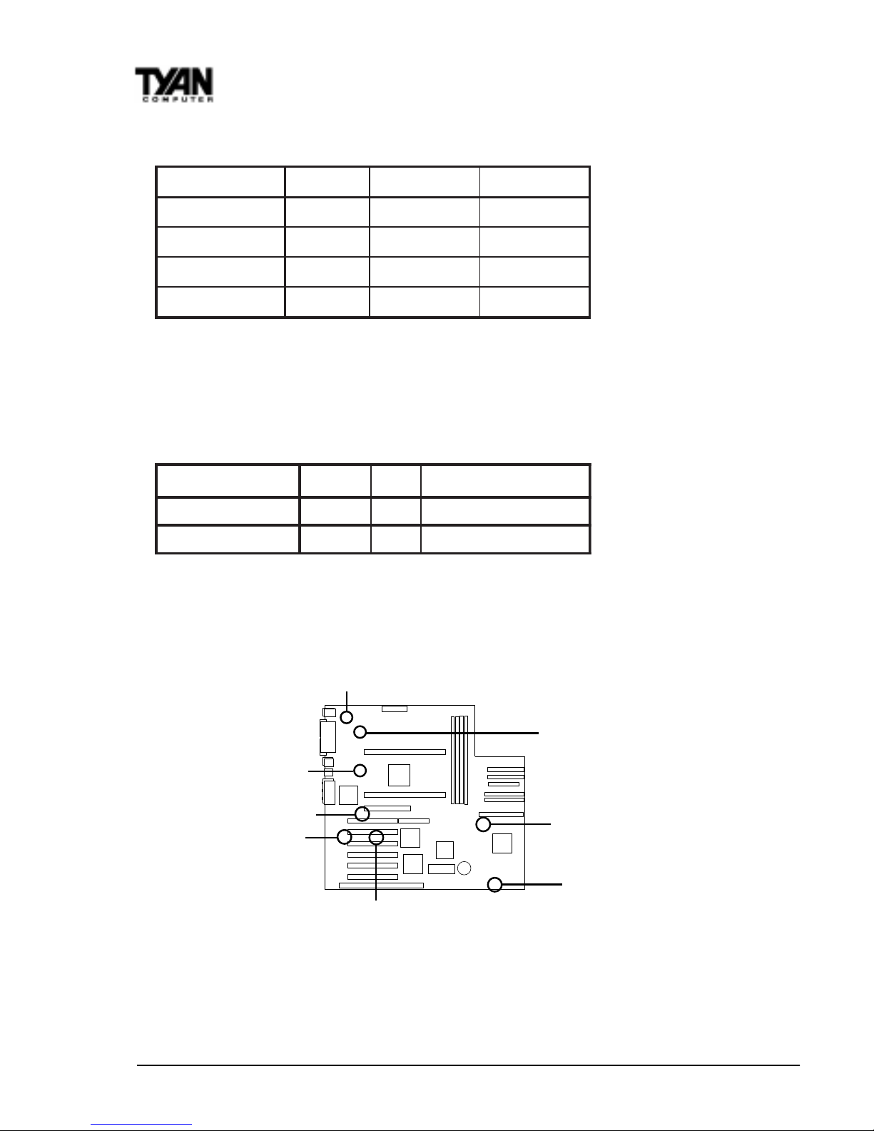
Enabling and Disabling Features
* Ethernet and Sound NOT on 1836DLU (default settings disabled).
Other Pin Assignments
repmuJdelbanE)tluafed(delbasiD
*tenrehtE
13PJFFONO
*dnuoS
61PJFFONO
ISCS
92PJFFONO
egdirBICP-ICP
03PJFFONO
12 3
4-1NAF DNGCCVrotinoMnaF
)NALno-ekaW(22PJ V5ybdnatSDNG)hgiHevitcA,nOrewoP(ekaW
JP31
JP16
JP29
JP30
FAN3
FAN1
FAN1
FAN4
 Loading...