

TYAN S1668 User Manual

Revision 1.2
TYAN S1668
Dual Pentium Pro ATX
440FX PCI-ISA System Board
User's Manual

Table Of Contents
1. Introduction.......................................................................3
1.1 Overview................................................................3
1.2 Hardware Specifications..........................................4
1.3 Software Specifications.......................................... 5
1.4 Environment........................................................... 5
2. Board Installation..............................................................6
2.1 Unpacking.............................................................. 6
2.2 Installation.............................................................. 6
3. S1668 On Board Resource Settings................................. 7
3.1 S1668Board Layout & Jumper Locations................ 7
3.2 Quick Reference for Jumpers.................................. 8
3.3 CMOS RTC............................................................11
3.4 Speaker Connector..................................................11
3.5 Turbo Switch.......................................................... 11
3.6 Turbo LED Connect................................................11
3.7 Reset Connector..................................................... 12
3.8 Flash EPROM Jumpers.......................................... 12
3.9 CMOS & Password Reset...................................... 12
3.10 DRAM Installation................................................ 13
3.11 CPU Installation.................................................... 15
3.12 VRM Installation...................................................16
3.13 Peripheral Device Installation.................................16
3.14Connecting The Power Supply............................... 16
4. BIOS Configuration...........................................................17
4.1 Entering Setup....................................................... 17
4.2 Control Keys......................................................... 18
4.3 Getting Help........................................................... 19
4.4 The Main Menu...................................................... 19
4.5 Standard CMOS Setup Menu...................................21
4.6 BIOS Features Setup.............................................. 24
4.7 Chipset Features Setup............................................27
4.7.1 Power Management Setup........................28
4.8 PCI Slot Configuration.............................................30
4.9 Integrated Peripherals............................................. 32
5. Flash Writer Utility............................................................36
6. System Resources.............................................................39
4.10 Load Setup Defaults..............................................33
4.11 IDE HDD Auto Detection..................................... 35
4.12 Save & Exit Setup.................................................35
5.1 The Flash Memory Writer Utility Screen...................38
6.1 Timer & DMA Channel Map................................... 39
6.2 Interrupt Map......................................................... 39
2S1668-ATX-001 http://www.tyan.com

1. Introduction
1.1 Overview
The S1668 is a quality, high performance dual processor mainboard based
on the powerful Intel Pentium Pro microprocessors. This mainboard is
designed around the latest and fastest Intel 440FX chipset and can support
CPU speeds of 150MHz through 200MHz.
The S1668 supports EDO memory, Burst EDO, ECC and memory parity
checking.The S1668's PCI Local Bus provides high performance capabilities that are ideal for a wide range of demanding applications such as:
CAD, CAM, CAE, networking, multi-user environments, database management, desktop publishing, image processing and 3D animation.
This integrated system board achieves the highest reliability and features
the industry standard "ATX" form factor. Some of the features included
are: on-board dual channel PCI IDE, on-board floppy controller, on-board
high speed I/O, Universal Serial Bus and on-board PS/2 mouse connector.
Flexibility and expandibility have been designed into the S1668. With I/O
and drive controller support built on-board, the five PCI and three ISA
(One ISA and one PCI as a shared slot) slots are free for add-on expansion
cards. With eight SIMM sockets, the S1668 can provide a very
flexible memory configuration of 8MB to 1024MB of RAM. With the
S1668's support for dual Pentium Pro processors, you can start a system
with just one CPU, and later add another, when more processing power is
required.
Remember to take a look at Tyan Computers web site located at
http://www.tyan.com. Here you can find information on all of Tyan's
products along with FAQ's, distributors list, drivers and CMOS setting
explanations.
3S1668-ATX-001 http://www.tyan.com

1.2 Hardware Specifications/Features
wCPU Intel Pentium Pro 150 thru 200 MHz (Socket 8)
(Single or Dual CPU configuration)
wCoprocessor On-chip floating point unit
wSpeed 60/66 MHz system bus
30/33 MHz PCI bus
7.5/8.33 MHz ISA bus speed
wDRAM 4 double banks of 72 pin SIMM sockets
Supports 5V or 3.3V memory
Supports BEDO(Burst Extended Data Out)
Supports EDO(Extended Data Out) DRAMs
Supports ECC(Error Correcting Code)w/ parity
Supports Fast Page Mode DRAMs
Supports 8MB to 1024MB of DRAMs
wL2 Cache 256/512KB 2nd level cache in CPU
wEIDE Controller Primary and secondary PCI EIDE channels on
board for support of up to four EIDE Mode 0
through Mode 4 drives.Supports DMA mode 1
and 2.
wEnhanced I/O Multi-mode bi-directional parallel port that
supports standard, EPP and ECP modes.
Supports 16550 compatible UARTS for on-board
high speed serial ports.
Support for an IrDA compliant InfraRed interface.
On-board floppy controller.
On-board USB(Universal Serial Port).
wMouse On-board PS/2 mouse connector.
wI/O Bus Slots 5 Master/Slave PCI-Bus
3 ISA Bus (One ISA and one PCI shared slot)
4S1668-ATX-001 http://www.tyan.com

1.3 Software Specifications
wBIOS Award or AMI BIOS
AT CMOS setup, BIOS/CHIPSET setup,
and hard disk utility included.
Support for easy BIOS upgrades with flash
EEPROM chip.
wO.S. Operates with MS-DOS, Windows 3.x, Windows
for Work Groups 3.x, Windows 95, Windows NT,
OS/2, Novell Netware, Novell UnixWare 1.1 and
SCO Unix.
1.3 Environment
Ambient Temperature 0 to +50 C (operating)
Relative Humidity 0 to +85% (operating)
Altitude 0 to 10,000 feet (operating)
Vibration 0 to 1,000 Hz
Voltage 4.9 to 5.2 V
Information presented in this publication has been carefully checked for
reliability; however, no responsibility is assumed for inaccuracies. The
information contained in this document is subject to change without
notice.
Award BIOS/Flash are trademarks of Award Software International Inc.
AMI BIOS is a trademarks of American Megatrends Inc.
IBM,PC,AT,PS/2 are trademarks of IBM Corporation
INTEL,Pentium Pro are trademarks of Intel Corporation.
Copyright c 1996 TYAN Computer Corp.
S1668, Titan Pro ATX.
Trademarks
5S1668-ATX-001 http://www.tyan.com

2. Board Installation
2.1 Unpacking
The mainboard package should contain the following:
wS1668 Mainboard
wOne IDE 40 pin cable
wOne 34 pin floppy cable
wUser's Manual
wOptional VRM(Voltage Regulator Module)
The mainboard contains sensitive electric components which can be easily
damaged by static electricity, so the mainboard should be left in its original
packaging until it is ready to be installed.
With the power supply pluged in and turned off touch an unpainted area of
the system chassis imedietly before handling the mainboard or any component. Doing so discharges the static charge your body may have built.
After opening the mainboard carton, extract the system board holding it by
its edges ,and place it only on a grounded anti-static surface, component
side up. Inspect the board for damage. Press down on all of the socket IC's
to make sure that they are properly seated. Do this only with the board
placed on an anti-static mat. Do not touch the bottom of the board.
DO NOT APPLY POWER TO THE BOARD IF IT HAS BEEN
DAMAGED!
2.2 Installation
You are now ready to install your mainboard. The mounting hole pattern of
the S1668 matches the ATX system board spec. It is assumed that the
chassis is for a standard ATX mainboard form factor.
6S1668-ATX-001 http://www.tyan.com
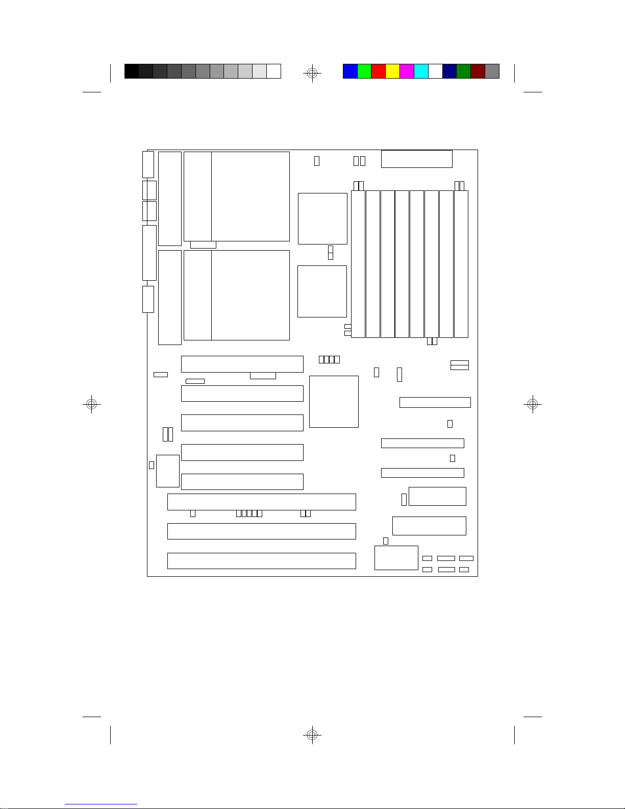
3. On Board Resource Setting
Figure 3.1 S1668 ATX Board Layout
PS/2
KB
PS/2
Mouse
VRM 1
pin 1
Parallel Port
Com1 Com2
VRM 0
USB1
pin 1
J18
pin 1
J28
J29
J30
USB2
CPU 1
Socket 8
J10
CPU 0
Socket 8
PCI Slot 1
J25
PCI Slot 2
PCI Slot 3
PCI Slot 4
PCI Slot 5
ISA Slot 1
pin 1
J20
J50
82441FX
J11
J12
82442FX
J21
82371SB
J49 J48
J14
J15
J22
J23
J24
J2
J3
Bank 0
Bank 0
1
J26
1
1
PWR CON. 5V
Bank 1
Bank 1
Bank 2
1
J27
Floppy Con.
1
Primary IDE
Secondary IDE
pin 1
BIOS
J32
AMI/AWARD
Bank 2
Bank 3
J17J16
CON4
pin 1
CON5
pin 1
J31
J5J4
Bank 3
J1
ISA Slot 2
ISA Slot 3
J41
RTC
Factory Default(do not change) Rev02 PCB
J31 off
J48 off
J49 off
7S1668-ATX-001 http://www.tyan.com
KB CTR
J43J42
pin 1
pin 1
J45 J46 J47
J44
pin 1
3.2 Jumper Settings:
CPU Speed: J27, J21, J22, J23, and J24
CPU Speed J27 J21 J22 J23 J24 J11 J12
150MHz 3-4 off on on on on off
166MHz 1-2 off on on on off on
180MHz 3-4 on off on on on off
200MHz 1-2 on off on on off on
Host Bus Speed/PCI Bus Speed: J27
Host Speed PCI Speed J27 J11 J12
60MHz 30MHz 3-4 on off
66.67MHz 33.33MHz 1-2 off on
CPU Clock Multiplier: J21, J22, J23 and J24
Multiplier J21 J22 J23 J24
X2 off off off off
X2.5 off on on on
X3 on off on on
X3.5 off off on on
X4 on on off on
CMOS Resest/Password Reset: J41(Default off)
If you forget your CMOS password or need to reset the
CMOS registers, just power off the system and close
jumper J41for five seconds. Then open jumper J41 and
power on the system. This will set the CMOS and password
back to the system default.
DRAM Voltage: J2, J3, J14, J15, J4, J5, J16 and J17(Default 5V)
(Some EDO memory is 3.3V)
Voltage J2 J3 J14 J15 J4 J5 J16 J17
3.3V on on on on off off off off
5V off off off off on on on on
Warning, damage to system can result if set incorrectly!
8S1668-ATX-001 http://www.tyan.com
I/O Selection: J28 & J29
J28 J29
For COM 1 and 2 1-2 1-2 Default
For InfraRed 2-3 2-3
Speaker Connector: J43
Pinout Assignments
1 Speaker out
2 Ground
3 Ground
4 + 5V
Keylock Connector: J44
Pinout Assignments
Pins 1 to 3 for power LED. 1 Led Output
2 No Connect
3 Ground
Pins 4 and 5 for Keylock 4 Keylock
5 Ground
Turbo Switch: J47 ( Non-Turbo Mode Not Supported )
HDD LED: J46
Pinout Assignments
1 Cathode
2 Anode
3 Cathode
4 Anode
Pins 1 and 2 are for primary IDE channel.
Pins 3 and 4 are for secondary IDE channel.
9S1668-ATX-001 http://www.tyan.com
Reset Connector: J45
Pinout Assignment
1 Power Good
2 Ground
Turbo LED Connector: J42
Pinout Assignment
1 Cathode
2 Anode
Flash EEPROM: J32(Default 5V)
This jumper should be left at the factory default.
Voltage J32
5V 1-2 (default)
12V 2-3
InfraRed Interface: Con4 and Con5
Pinout Assignment
1 Signal In
2 Gnd
3 Signal Out
4 VCC
Super I/O Type: J26
This setting depends on what type of SMC I/O chip
is installed on the board. This jumper is set at the
factory and should not be changed.
Type J26
665IR 1-2
669IR 2-3
10S1668-ATX-001 http://www.tyan.com
Soft Power On Switch: J1
Pinout Assignment
1 Soft Power On
2 Ground
CPU FAN Power: J49 and J50
Pinout Assignment
1 12Volts
2 Ground
3.3 CMOS RTC
CMOS RTC includes an internal battery and Real Time Clock circuit. It
provides the date and the time for the system. Normally the life span of a
RTC internal battery is 10 years. When replacing, you should use the same
model.
3.4 Speaker Connector Installation
S1668 provides a 4-Pin header (J43) to connect the speaker. The polarity
can go either way.
3.5 Turbo Switch
The front panel on your case may have a turbo switch to control system
speed when slower program execution is required for software developed
in the old XT days. The Intel 44FX chipset doesn't support a de-turbo
mode, but the S1668 has a connector (J47) for the cable that may come has
a connector (J47) for the cable that may come with the case.with the case.
3.6 Turbo LED Connector Installation
The TURBO LED on the front case panel can indicate the current speed
status of the system. The TURBO LED connector should be installed to
J42 in the correct direction.
11S1668-ATX-001 http://www.tyan.com

3.7 Hardware Reset Switch Connector Installation
The RESET switch on your cases' display panel provides users with the
HARDWARE RESET function which is the same as power on/off. The
system will do a cold start after the RESET switch is pushed by the user.
The RESET switch is a 2 pin connector and should be installed on jumper
J45.
3.8 Flash EEPROM-Jumper J32
The S1668 uses flash memory to store BIOS data. It can be updated as
new versions of the BIOS becomes available. The flash utility will guide
you through the process step by step. If your system is functioning properly,
you may want to forego updating your BIOS in the event the new one
causes problems with your existing hardware and software.
J32 determines which type of EPROM is used. This jumper has been set to
match the on board BIOS chip. The factory default for the S1668 is on pins
1-2.
Refer to chapter 6 for Flash EEPROM upgrade procedures.
3.9 Hardware CMOS & Password Reset
(The following steps are valid provided the board has a DS12887A RTC)
If you have been locked out of your system because you forgot your password or set the CMOS incorrectly, follow the instructions below.
a. Power off the system
b. Short jumper J41.
c. Wait for 5 seconds then remove the jumper from J41.
d.Then power on the system again.
By doing the above procedures, your password will be erased and the CMOS
will be reset to the BIOS defaults.
12S1668-ATX-001 http://www.tyan.com
 Loading...