

TYAN S1590, S1590-100 User Manual

Tyan S1590
Trinity 100AT
Motherboard User’s Manual
Revision 1.50
Copyright © Tyan Computer Corporation, 1999. All rights reserved. No part of this
manual may be reproduced or translated without prior written consent from Tyan
Computer Corp.
All registered and unregistered trademarks and company names contained in this
manual are propery of their respective companies including, but not limited to the
following.
AwardBIOS is a trademark of Award Software Inc.
Windows is a trademark of Microsoft Corporation.
IBM, PC, AT, PS/2 are trademarks of IBM Corporation.
INTEL, Pentium, Pentium MMX are trademarks of Intel Corporation.
S1590 Trinity 100AT is a trademark of TYAN Computer Corporation.
Information contained in this publication has been carefully checked for accuracy and
reliability . In no event will Tyan Computer be held liable for any direct or indirect,
incidental or consequential damage, loss of use, loss of data, or other malady resulting
from errors or inaccuracies of information contained in this manual. The information
contained in this document is subject to change without notice.
PRINTED IN USA

T able of Contents
1. Introduction.....................................................................................................4
Overview ..................................................................................................... 4
Icons............................................................................................................5
Hardware Specifications/Features.......................................................... 5
Software Specifications............................................................................ 7
T echnical Support......................................................................................7
Returning Merchandise for Service........................................................8
2. Board Installation.......................................................................................... 9
Unpacking...................................................................................................9
Precautions.................................................................................................9
Installation Steps.......................................................................................1 0
What is a Jumper?..................................................................................... 1 1
Map of Motherboard Jumpers.................................................................1 2
Picture of Motherboard Features............................................................1 3
Setting Jumpers..........................................................................................14
Mounting the Motherboard in the Chassis...........................................1 7
Installing Memory ......................................................................................1 7
Installing CPU and Cooling Fan..............................................................2 1
Connecting IDE and Floppy Drives........................................................2 2
Connecting the Power Supply ................................................................. 2 4
Installing Add-on Cards...........................................................................26
Connecting PS/2, USB, Serial & Parallel Devices................................. 2 7
Frequently Asked Questions...................................................................2 7
3. BIOS Configuration......................................................................................32
Introduction to Setup................................................................................3 2
Main Setup Menu......................................................................................35
Standard CMOS Setup..............................................................................37
BIOS Features Setup.................................................................................4 0
Chipset Features Setup.............................................................................4 5
Power Management Setup....................................................................... 4 8
PnP/PCI Setup............................................................................................5 3
Integrated Peripherals...............................................................................5 6
User Password........................................................................................... 5 8
Flash Writer Utility .....................................................................................5 9
4. System Resources......................................................................................... 62
POST Messages........................................................................................ 6 2
.

Appendix 1 - Glossary ........................................................................................66
http://www.tyan.com
4
Chapter 1
Introduction
Overview
The S1590S-100 (S1590) T rinity 100A T is a quality , high performance mainboard
designed for Socket 7 microprocessors. This mainboard utilizes the VIA MVP3
100MHz AGPset and host bus speeds of 66MHz to 100MHz. For CPU speed
support, please refer to the CPU Compatibility Chart in Tyan’s website
(http://www .tyan.com/support/html/socket_7_compatibility.html). The T rinity
100AT also has 100MHz Front Side Bus support, which allows you to take full
advantage of 100MHz SDRAM memory modules.
The S1590 mainboard, with built-in AGP slot, provides high performance
capabilities that are ideal for a wide range of demanding applications such as
CAD, CAM, CAE, desktop publishing, 3D animation, and video production.
This system board achieves high reliability with numerous features and yet is
small enough to be supported in a Baby AT form factor. Some of the features
included are onboard dual channel PCI PIO, Bus Master IDE and UltraDMA/
33, onboard floppy controller, and onboard high speed I/O.
Flexibility and expandability have been designed into the T rinity 100AT . W ith
I/O and drive controller support built onboard, the one AGP slot, four PCI and
four ISA slots (one shared, eight usable) are free for numerous add-on expansion cards.
chapter 1
Introduction
S1590 Trinity 100A T
5
Remember to take a look at TYAN Computer’s web site located at
http://www .tyan.com. There you can find information on all of TYAN’s
products along with F AQs, distributors list, drivers, and BIOS setting explanations.
Icons
In order to help you navigate this manual and set up your system, we have
added several icons to our format.
This icon alerts you to particularly important details regarding the
setup or maintenance of your system. This icon often appears next
to information that may keep you from damaging your board or
system. While we will often point out the most vital paragraphs in a
chapter, you should always read every word in the text. Failing to do so can
lead to exasperation and expense.
Wherever possible, we have included step-by-step instructions for
setting up your system, which are indicated by this icon. However, it
is in your best interest to read an entire section (and perhaps the
entire manual) before you begin to fiddle with your motherboard.
While we have alerted you to potential dangers in several places in
the manual with this icon, these warnings should not be regarded as
the whole of your safety regimen. Never forget that computers are
electrical devices, and are capable of delivering a shock. Prevent
damage to yourself and to your board: always ensure that your system is
turned off and unplugged whenever you are working with it, and that you are
equipped with a static safety device.
Hardware Specifications/Features
Processor Information* •Intel Pentium/Pentium MMX
•AMD K5/K6/K6-2
•Cyrix/IBM 6x86/6x86MX
•IDT C6/C6+
•Maximum rated bus speed 100MHz
!!
!!
!
important!
procedure
1.
2.
3.
warning
INTRO

http://www.tyan.com
6
Chapter 1
Introduction
Chipset Information •VIA MVP3 AGPset.
V oltage and Power •AT/ATX power supply connectors.
Information •+12V power source for DC fan onboard.
•3.3V or 5.0V DRAM support.
•Utilizes GTL+ bus to reduce power consumption
and EMI.
•Switching power supply onboard.
•W ake-on LAN 3-pin header (requires ATX 2.01
compliant power supply).
Main Memory •Up to 384MB onboard.
•Three 168-pin DIMM sockets.
•T wo 72-pin SIMM sockets.
•Maximum rated memory bus speed 100MHz.
•Supports EDO, SDRAM, Parity , and ECC (ECC only
with Parity memory).
•1024KB level 2 pipeline burst cache
Expansion Slots •One 32-bit AGP slot.
•Four 32-bit PCI Bus Master slots.
•Four 16-bit ISA slots.
•One shared, eight usable slots.
•Maximum rated PCI bus speed 33MHz
Physical Dimensions •Mini AT design.
•11.1 inches x 8.75 inches (reduced form factor).
BIOS Information •A ward Plug and Play fla sh BIOS.
•Deep Green, Energy Star , Y ear 2000, ACPI, PC97-98,
DMI 2.0 compliant.
•PC-98 ready .
•Soft power down, multiple boot options.
Disk Drive & System I/O •UltraDMA/33 (UIDE) built-in (up to
33MB/s DTR).
•T wo PCI bus mastering EIDE channels.
•Supports EIDE CD-ROMs.
•PIO Mode 3+4 (up to 17MB/s DTR).
•Bus mastering mode (up to 22MB/s DTR).
•Support for two floppy drives

S1590 Trinity 100A T
7
INTRO
(supports Mode 3 and up to 2.88MB).
•T wo serial ports (16550 UAR T s).
•One ECP/EPP parallel port.
•One IR (InfraRed) I/O interface port header .
•T wo USB rev 1.2 port headers.
•One PS/2 mouse port.
•One AT keyboard connector.
* For the latest CPU compatibility list see www.tyan.com
Software Specifications
OS •Operates with MS-DOS, W indows 3.x, W indows
for W orkGroup 3.x, W indows 95, Windows 98,
W indows NT , OS/2, Novell Netware, Solaris, and
SCO Unix.
T echnical Support
If a problem arises with your system, you should turn to your dealer for help
first. Your system has most likely been configured by them, and they should
have the best idea of what hardware and software your system contains.
Hence, they should be of the most assistance. Further, if you purchased your
system from a dealer near to you, you can actually bring your system in to
them to have it serviced, instead of attempting to do so yourself (which can
have expensive consequences).
Help resources:
1. See FAQ and beep codes sections of this manual.
2. See Tyan web site for F AQ, bulletins, driver updates, etc.
http://www .tyan.com
3. Contact your dealer or distributor for help BEFORE calling T yan.
4. Email T yan tech support: techsupport@tyan.com
5. Call T yan tech support: 510-440-8808

http://www.tyan.com
8
Chapter 1
Introduction
Returning Merchandise for Service
During the warranty period, contact your distributor or system vendor FIRST
for any product problems. This warranty only covers normal customer use and
does not cover damages incurred during shipping or failure due to the
alteration, misuse, abuse, or improper maintenance of products.
For Resellers Only:
A receipt or copy of your invoice marked with the date of purchase is required
before any warranty service can be rendered. You can obtain service by calling
the manufacturer for a Return Merchandise Authorization (RMA) number . The
RMA number should be prominently displayed on the outside of the shipping
carton and the package should be mailed prepaid, or hand-carried to the
manufacturer . TYAN will pay to have the board shipped back to you.
S1590 Trinity 100A T
9
chapter 2
Board Installation
Unpacking
The mainboard package should contain the following:
(1 ) S1590 mainboard
( 1) 40-pin IDE and 34-pin floppy cable pack
(1 ) S1590 User’ s Manual
(1) Serial/parallel cable set
(1) PS/2 mouse cable
(1 ) Driver CD
Precautions
What’s the first thing I should do?
The first thing you should do is read this user’s manual. It contains important
information which will make configuration and setup much easier.
Here are some precautions you should follow when installing your motherboard:
INSTALL

http://www.tyan.com
10
procedure
1.
2.
3.
Chapter 2
Board Installation
!!
!!
!
important!
(1) Ground yourself properly before removing your motherboard
from the antistatic bag. Unplug the power from your computer
and then touch any metal part on the computer case. (Or wear a
grounded wrist strap.)
(2) Hold the motherboard by its edges and do not touch the bottom of
the board.
(3) A void touching motherboard components, IC chips, connectors,
and leads.
(4) A void touching pins of memory modules and chips.
(5) Place motherboard on a grounded antistatic surface or on the
antistatic bag.
Having reviewed the precautions above, the next step is to take the motherboard out of the cardboard box and static bag, hold it by its edges, and place it
on a grounded antistatic surface, component side up. Inspect the board for
damage.
DO NOT APPL Y POWER TO THE BOARD IF IT HAS BEEN DAMAGED!
Press down on any of the socket ICs if it appears that they are not properly
seated (the board should still be on an antistatic mat). Do not touch the
bottom of the board. Remember, don’ t take any electronic device out of its
protective bag until you are ready to actually install it into the computer case.
If you do not ground yourself, you risk zapping the motherboard or adapter
card. Subsequent problems may not arise immediately because electrostatic
discharge damage, unlike physical damage, causes the device to fail over time.
*Power Supply Requirement: If you use an A TX Power Supply , it should be
2.01 compliant. S tandby current must be 750mA or higher (SB5V = 0.75A)
Installation Steps
You are now ready to install your mainboard. The mounting hole pattern of the
S1590 matches the Baby AT system board specifications. Your chassis should
have standard A T mainboard form factor mounting holes and either an AT or
ATX power supply.
1. Set Jumpers
2. Mount Motherboard in Chassis
3. Install Memory
warning

S1590 Trinity 100A T
11
INST ALL
4. Install CPU & Cooling Fan
5. Connect IDE and Floppy Drives
6. Connect Power Supply
7. Install Add-on Cards
8. Connect PS/2, USB, Serial and Parallel Devices
What is a Jumper?
In this manual, the terms “closed” and “on” are used when referring to jumpers
(or jumper pins) that are active; “open” and “off” are used when referring to
jumpers (or jumper pins) that are inactive. See the Figure 2-1 for examples of
“on” and “off” pins and jumpers. The square pin in the diagram is Pin 1.
Jumpers and pins are connected by slipping the blue plastic jumper connector
overtop of two adjacent jumper pins (indicated by 1-2 or 2-3). The metal rod
inside the plastic shell bridges the gap between the two pins, completing the
circuit. See Figure 2-2 for more examples of pin connections.
The tables and maps on the following pages will help you set the jumpers for CPU
speed, Infrared, and external connector pin assignments, among others. The
miniature motherboard maps will help you locate the jumpers on your board. A
full-page map of the motherboard can be found on the next two pages.
2 pin jumpers
off on
3 (or more) pin jumpers
1-2 2-3 open
1
2
3
1
2
3
1
2
3
Figure 2-1
Figure 2-2

http://www.tyan.com
12
Chapter 2
Board Installation
The tiny number “1”s next to jumpers of 3 pins or more indicate the position of
pin 1 for that jumper.
Map of Motherboard Jumpers
PCI slot 2
PCI slot 3
AGP port
PCI slot 4
PCI slot 1
3 volt
lithium
battery
VIA MVP3
chipset
VIA MVP3
chipset
Floppy drive connector
Keybrd
ATX power connector
AT power connector
ISA slot 4
ISA slot 3
ISA slot 2
ISA slot 1
Award BIOS
DIMM bank 2
DIMM bank 1
DIMM bank 3
SIMM bank 1
SIMM bank 1
Primary IDE connector
Secondary IDE connector
LPT1 connector
ZIF Socket 7
JP8
JP9
JP10
JP3
JP4
JP5
JP6
J4 (CPU Fan)
JP1
JP12
JP7
JP11
J1
(Fan)
J10
(Fan)
J3
(WOL)
PS/2
Mouse
header
USB
JPW1
J8
J5
Com 2
Com 1
1
3
1
3
1
5
JP2
JP13
1
2
9
JP14
Ring1
(WOR)
JVBA T
S1590 Trinity 100A T
13
INST ALL
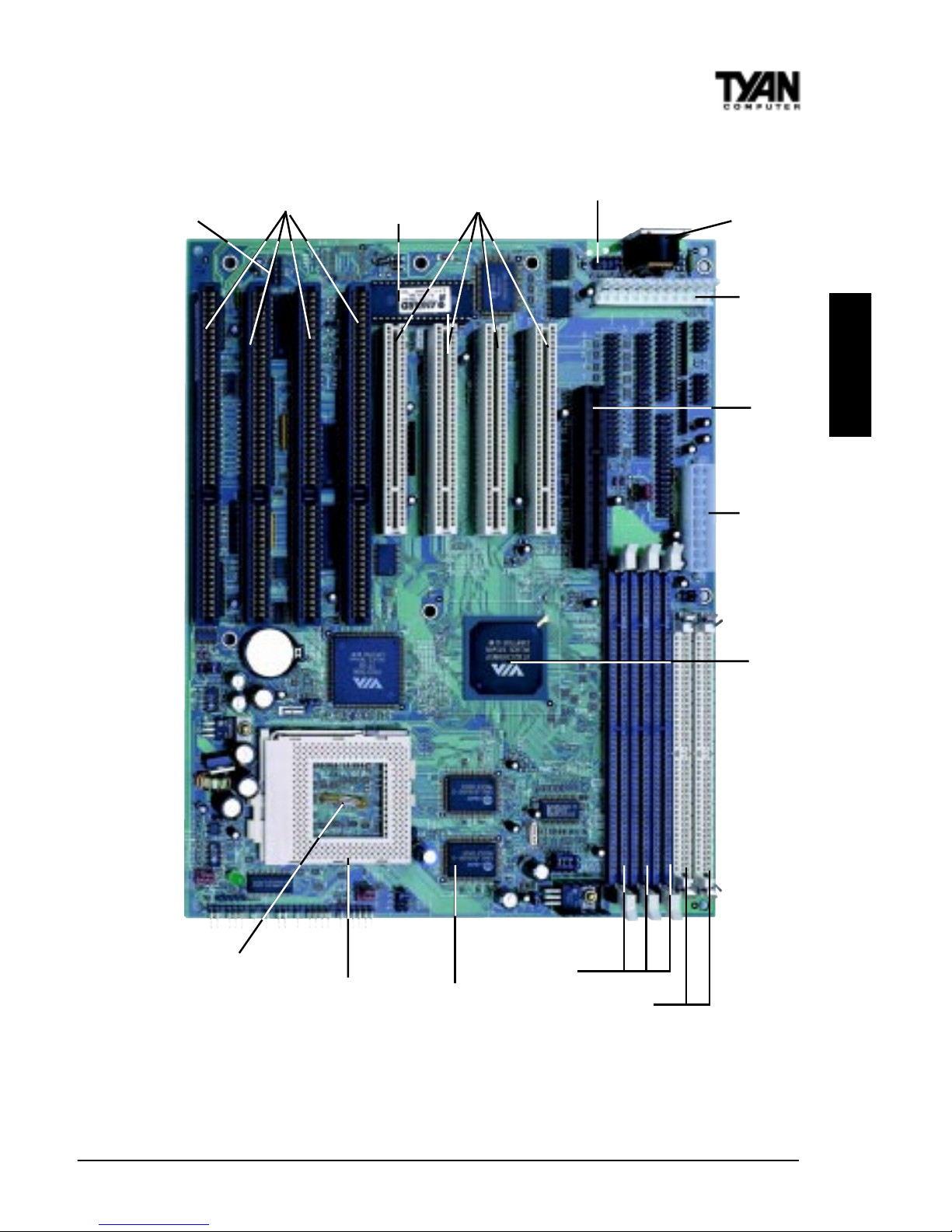
Picture of Motherboard Features
3 DIMM slots
Award BIOS
AGP port
4 ISA slots
4 PCI slots
VIA MVP3
ZIF Socket 7
PS/2 mouse port
ATX power
connector
AT power
connector
2 SIMM slots
AT
Keyboard
port
CPU
temperature
sensor
1MB L2
cache
USB
header
http://www.tyan.com
14
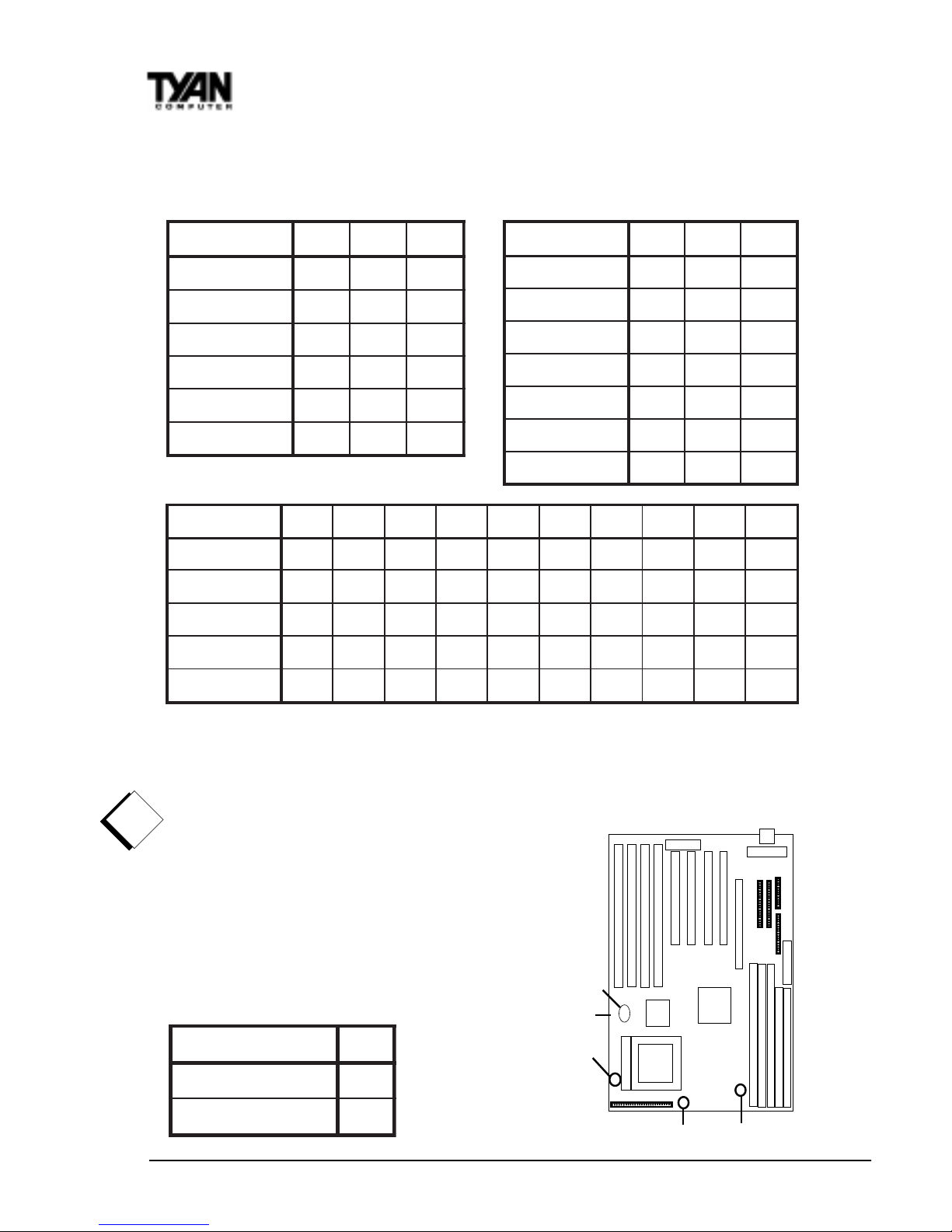
1. Setting Jumpers
** Default Setting (2.2V)
The CPU speed is controlled by setting the bus speed and the multiplier with
the jumpers described above that are appropriate for your CPU and memory .
Y ou must have a 100MHz processor AND PC/
100 memory to run at a bus speed of 100MHz.
T yan does not recommend operating CPUs,
memory or PCI bus at higher than rated speed.
Tyan takes no responsibility for any problems
related to overclocking any bus or componenet
on the system board.
Chapter 2
Board Installation
deepSsuB3PJ4PJ5PJ
zHM06
3-23-23-2
zHM66
2-13-23-2
zHM57
2-12-13-2
zHM38
2-13-22-1
zHM59
3-22-12-1
zHM001
2-12-12-1
reilpitluM8PJ9PJ01PJ
x5.1
FFOFFOFFO
x5.2
NONOFFO
x3
NOFFOFFO
x5.3
FFOFFOFFO
x4
FFONONO
x5.4
NONONO
x5
NOFFONO
1WPJV0.2
V1.2**V2.2V3.2V4.2V7.2V8.2V9.2V2.3
V3.3
2-1
FFONOFFONOFFONOFFONOFFONO
4-3
NOFFONONOFFONOFFOFFOFFOFFO
6-5
NOFFOFFOFFONONOFFOFFONONO
8-7
NOFFOFFOFFOFFOFFONONONONO
01-9
NOFFOFFOFFOFFOFFOFFOFFOFFOFFO
!!
!!
!
important!
11PJ
VUPC
eroC
V=
O/I
NO
tluafeD
FFO
1-A. CPU Bus Speed Settings 1-B. CPU Clock Multiplier
1-C. CPU Core Voltage Settings
1-D. JP1 1 Split V oltage Setting
JP3,4,5
JP8,9,10
JPW1
JP11
S1590 Trinity 100A T
15
INST ALL
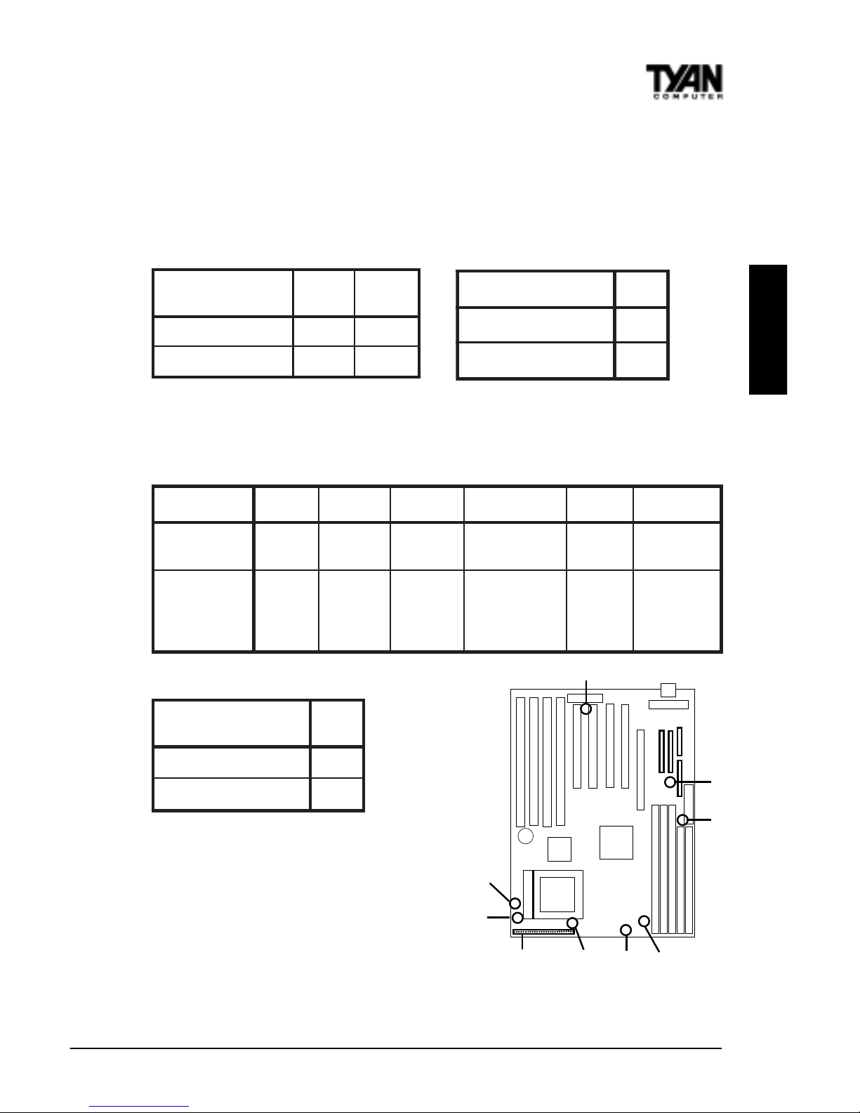
JP11 is used to set CPU I/O voltage. Most newer P55C type CPUs such as AMD K6/
K6-2 have 3.3V I/O volt
age and a lower core voltage, so this jumper should be
OFF . For certain older P54C type CPUs the Core voltage is the same as the I/O
voltage so this jumper should be closed (on). Check the specs on your CPU
before you set this jumper .
Note: AGP Clock Speed is 66MHz.
CPU Clock Speed is set in
section 1-A on previous page.
**Note: JP7 and JP14 are provided on
some S1590 boards. If your board does
not have JP7 and JP14, please disregard
the above chart - the correct settings
are already built-in to the motherboard.
sniP2-111-661-3102-8132-2272-42
noitcnuF
rewoP
ffO/nO
deRarfnIDELDDHDELrewoP
teseR
hctiwS
rekaepS
tnemngissA
rewoP=1
ffO/nO
DNG=2
V5=6
XRRI=8
DNG=9
XTRI=01
V5=31
-DEL=51
+DEL=61
DELpeelS=81
DELrewoP=02
DNG=22
teseR=32
V5=42
lanretnI=62
rekaepS
-rekaepS=72
egatloVMMIS
,1PJ
21PJ
,2PJ
31PJ
V5
NOFFO
V3
FFONO
:saemaS6PJ
kcolCUPC
2-1
kcolCPGA
3-2
1-E. SIMM V oltage Settings 1-F. Memory (DIMM)Clock Speed
1-G. J5 External Pin Assignments
,7PJ
41PJ
ylppusrewopTA
NO
ylppusrewopXTA
FFO
1-H. Power Supply T ype**
JP7,
JP14
J4
(CPU Fan)
J5
WOL
J1
(Fan)
JP1,2
12,13
JP6
J10
(Fan)
JP11
http://www.tyan.com
16
Chapter 2
Board Installation
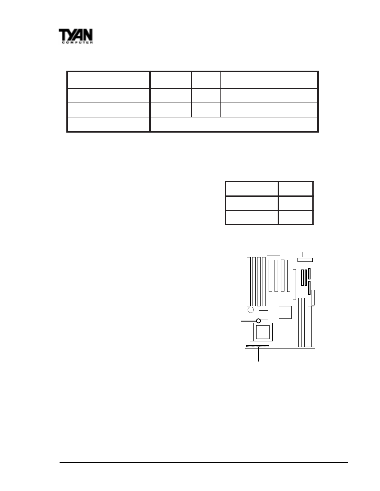
Hardware CMOS & Password Reset
If you have been locked out of your system because you forgot your password or set the CMOS incorrectly , follow the instructions below .
1. Power off the system
2. Set jumper JVBA T1 to pins 2 and 3
3. Wait for 2 seconds, then return
jumper JVBAT1 to pins 1 and 2.
4. Power on the system again.
By following this procedure, you will erase your
password and reset the CMOS to the BIOS defaults.
Soft Power Connector
The Soft Power Connector is located on pins
1 and 2 of jumper block J5. Pressing the Soft
Power Button will turn the sytem on and off.
Holding this button for more than four
seconds (when the system is on) will power
down the system. Pressing it again will reboot
the system.
Speaker Connector Installation
The T rinity 100AT provides a 4-pin header to
connect the speaker. The speaker is connected to pins 24-27 of jumper block J5.
Hardware Reset Switch Connector Installation
The Reset switch on your case’s display panel provides you with the Hardware
Reset function, which is the same as power on/off. The system will do a cold
start after the Reset button is pushed. The Reset switch is a 2-pin connector
and should be installed on pins 22 and 23 of jumper block J5.
1TABVJ
tluafeD
2-1
SOMCteseR
3-2
J5
JVBAT1
12 3
)NALno-ekaW(3J V5ybdnatSDNG)hgiHevitcA,nOrewoP(ekaW
01J&4J,1JsnaF DNGCCVrotinoMnaF
)kcolyek(8J sesacTAredlorofredaehkcolyeK
1-J. Other Pin Assignments
S1590 Trinity 100A T
17
INST ALL
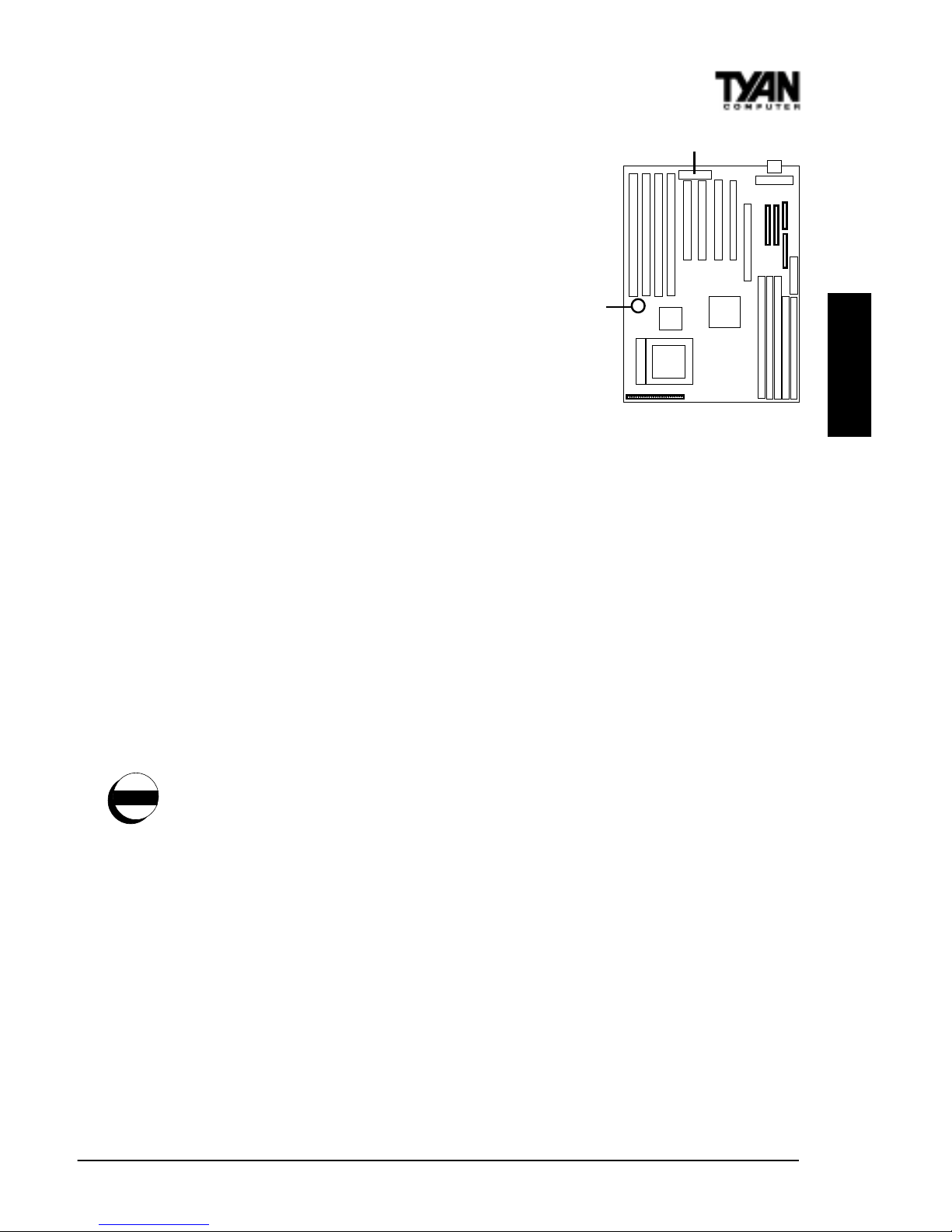
CMOS RTC
The VIA MVP3 AGPset includes a Real Time
Clock (RTC) circuit, which provides the date
and time for the system. If the external
battery for the RTC is low , it will prevent
your system from POSTing, and you will not
get a display . Normally the life span of an
external battery is 2 years. If yours is
running low , you will need to replace it with
a new 3V lithium battery (Sony CR2032).
Flash EEPROM
The Trinity 100AT uses flash memory to store BIOS programs. It can be easily
updated if necessary using the flash utility (see page 59). Tyan does not
recommend flashing the BIOS unnecessarily . Check the Tyan web site for the
latest BIOS revision.
2. Mounting the Motherboard in the Chassis
Follow the instructions provided by the case manufacturer for proper installation guidelines. TYAN recommends that you use only one screw to hold down
the motherboard. The rest of the mounting holes should be used for the plastic
standoffs. If your case does not have a hole for a standoff, simply cut off the
bottom of the plastic standoff so that the flat portion rests on the metal. The
adapter cards and the screws holding them down will keep your board flat. The
fastening screw should not short any of the traces on the motherboard. Make
certain that you do not overtighten the screw , as it will damage the mother board and possibly break internal traces in the surrounding area. The hole you
should use is located at the top-center of the board where the adapter cards
are fastened to the case.
3. Installing Memory
Since TYAN boards are manufactured with performance in mind, you should
use add-in components that match. Some DIMM modules may seem to be high
quality because of name or feel but that does not guarantee real-world
usability . Some cheaper or OEM memory may have brand-name components,
but they may contain inferior or substandard parts which do not meet the
critical tolerances our products require. Because of this, your memory may not
work correctly in a TYAN board though it may work well in a competitor’s
BIOS
Battery
warning
http://www.tyan.com
18
Chapter 2
Board Installation
board. This is because many of our competitors do not adhere to the strict
tolerances required for high performance. If you buy a TYAN board, you are
getting the best system available. To make installation easy and trouble free,
get high quality parts. Some brands we recommend are Corsair Microsystems,
Kingston Memory, and QesTec Incorporated. These DIMMs have proven to
be very stable on our boards and perform extremely well.
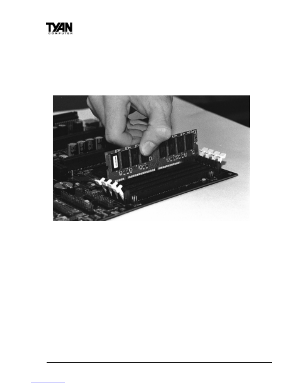
To install your DIMMs, line your module up so that the pins fit into the slot.
There is only one way that your DIMM can fit properly . Make sure that the
short row of pins is lined up with the short gap in the DIMM slot. Figure 2-3
above shows how to sit the DIMM into its slot. To insert the DIMM, push
down vertically on the module with even force, as shown in the photo. Do not
shove one end in first; doing so will bend the DIMM pins.
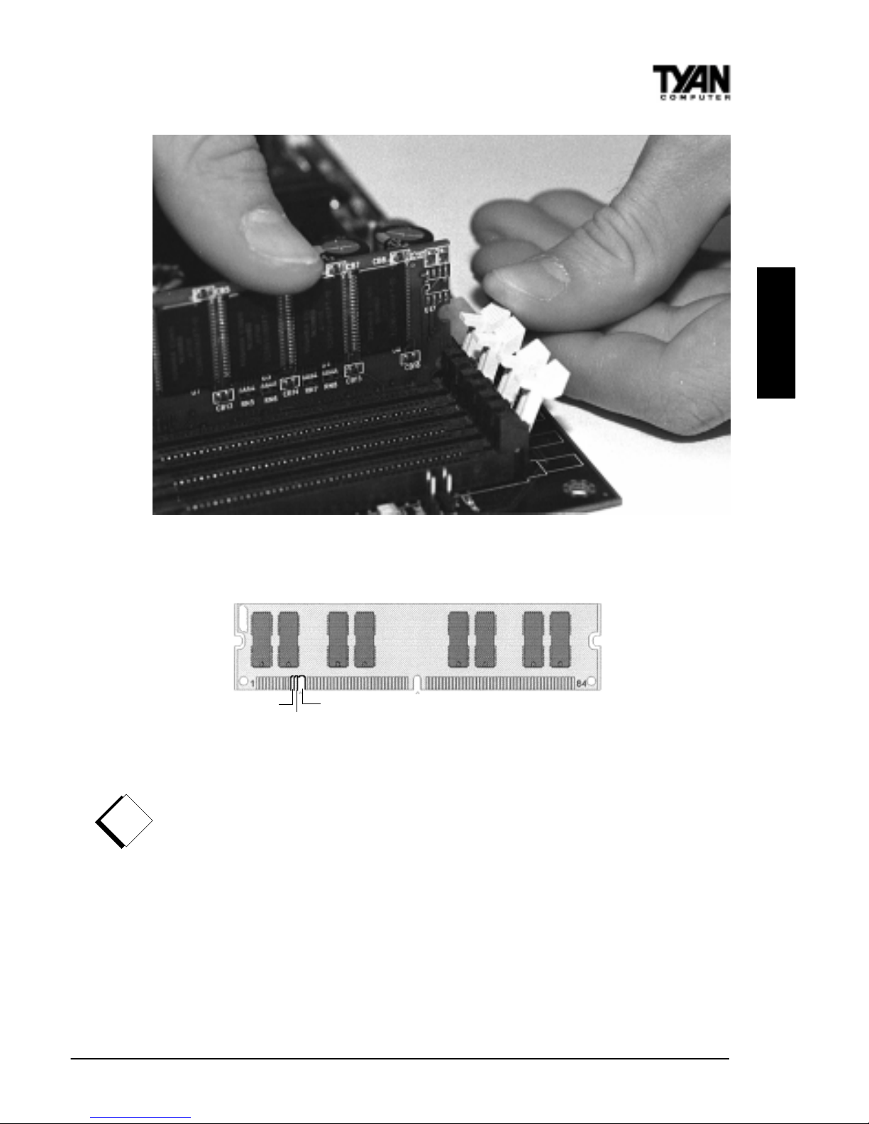
To lock the DIMM into place, push the plastic clips on either end of the slot
onto the notches in the ends of the DIMM (see Figure 2-4 on the next page).
T o remove your DIMM, simply pull the clips back, and pull up on the module.
Place the DIMMs in an anti-static bag as soon as you remove them to avoid
static damage.
The T rinity 100AT uses a 64-bit data path from memory to CPU and can
accommodate up to 384MB of SDRAM. The 168-pin DIMMs (Dual In-line
Memory Modules) must be of the 3.3V, unbuffered variety . The position of the
Figure 2-3
S1590 Trinity 100A T
19
INST ALL
notch in the SDRAM key position will tell you whether or not a DIMM is
unbuffered (see the Figure 2-5 below). All installed memory will be automatically detected, so there is no need to set any jumpers.
Figure 2-5
Some details of memory installation:
• At least one unbuffered DIMM must be installed for the system to POST.
• The mainboard supports 32MB, 64MB, 128MB SDRAM.
• PC-100 DIMM is required if CPU bus speed is at 100MHz
• EDO, SDRAM, Parity , and ECC (using Parity memory) memory is sup-
ported.
• SIMM modules must be installed in pairs, and both must be of the same
size and type.
• The mainboard supports 4MB, 8MB, 16MB, 32MB, and 64MB SIMMs.
• You can install either single- or double-sided SIMMs.
• Two SIMMs or one unbuffered DIMM must be installed for the system to
!!
!!
!
important!
RFU
Buffered
Unbuffered
168-pin DIMM
Figure 2-4

http://www.tyan.com
20
Chapter 2
Board Installation
POST .
The table below shows some of the possible memory configurations. Not all
possible configurations are listed.
Note: You can NOT use DIMM Bank 1 and SIMM Bank 1 at the same time!
Bank 1 can not be shared!
Cache Memory
The S1590 has 1024Kbit of onboard pipeline burst SRAM. This SRAM cannot
be upgraded.
MMID
1knaB
MMID
2knaB
MMID
3knaB
MMIS
1knaB
latoT
1xBM800
0
BM8
1xBM81xBM80
0
BM61
1xBM81xBM81xBM8
0
BM42
1xBM611xBM81xBM8
0
BM23
01xBM611xBM61
2xBM8
BM84
1xBM611xBM611xBM61
0
BM84
1xBM231xBM611xBM61
0
BM46
1xBM231xBM23
1xBM80
BM27
01xBM23
1xBM232xBM61
BM69
1xBM461xBM231xBM23
0
BM821
1xBM461xBM461xBM23
0
BM061
1xBM461xBM461xBM46
0
BM291
1xBM8211xBM461xBM46
0
BM652
1xBM8211xBM8211xBM46
0
BM023
1xBM8211xBM8211xBM821
0
BM483
S1590 Trinity 100A T
21
INST ALL
4. Installing the CPU and Cooling Fan
Socket 7 processors (see Specifications on page 5) can be used on the Trinity
100A T . Please refer to page 14 for the correct CPU jumper settings for your CPU.
Remember:
• The CPU is a sensitive electronic component and it can easily be damaged
by static electricity . Do not touch the CPU pins with your fingers.
• Before the CPU is installed, the mainboard must be placed on a flat
surface. You should be able to insert the CPU with minimal, but firm,
pressure. Do not press down hard on the CPU.
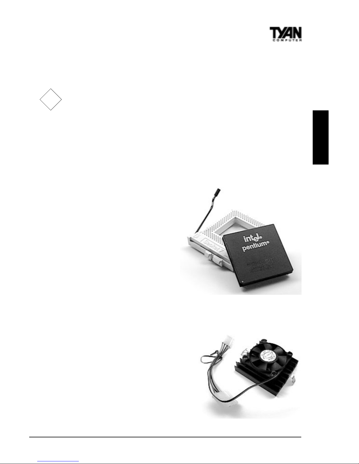
In Figure 2-6, you can see the CPU and the ZIF socket. Notice that the arm of
the ZIF socket is up. When this arm is up, the CPU is unlocked from the socket
and allows you to remove or install a CPU. As the ZIF socket is keyed to the
processor that you are using, you will only be able to install the CPU one way ,
thus eliminating the chance for error.
Pin 1 on the CPU is denoted by a
small dot on one of the corners and
Pin 1 on the ZIF socket is denoted
by an angled corner. Never force a
CPU into a socket. Forcing a CPU to
seat will bend the pins on the CPU
and possibly damage the motherboard. Check with your vendor or
manufacturer for proper voltage
selection.
Push down lightly on the CPU, and
lower the arm on the ZIF socket to
secure the CPU. A squeaking noise is
normal as the arm lowers. After the
CPU is securely seated, install the
appropriate cooling device (Figure 2-
7). Tyan strongly recomends a
heatsink/fan combination. Consult
with your case manufacturer for other
cooling options.
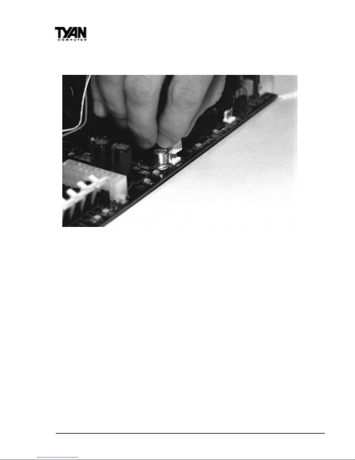
Locate the cooling fan connector (e.g.
CPU Fan, J4) on the motherboard. Plug
the CPU’ s cooling fan cable into the cooling fan connector on the board. There
!!
!!
!
important!
Figure 2-7
Figure 2-6
http://www.tyan.com
22
will be a plastic clip assembly similar to that of the A TX power connector that will
force you to connect the fan cable correctly (see Figure 2-8 below).
Figure 2-8
5. Connecting IDE and Floppy Drives
The colored stripe on a ribbon cable should face toward the keyboard connector . In Figure 2-9 on the next page, you can see how the IDE cables should
look when they are connected to your hard drive. Notice how Pin 1 (denoted
by a red stripe) is connected so that it is next to the power connector of the
drive. The primary IDE connector is black; the secondary IDE connector is
white.
In most cases, this is the proper way of connecting your IDE cable to the
harddrive. Figure 2-10 on the next page shows the IDE cable properly connected to the motherboard. Contact your hard disk drive manufacturer or
documentation for more information.
Some symptoms of incorrectly installed HDDs are:
• Hard disk drives are not auto-detected: may be a Master / Slave problem
or a bad IDE cable. Contact your vendor.
• Hard Disk Drive Fail message at bootup:may be a bad cable or lack of
power going to the drive.
Chapter 2
Board Installation
 Loading...