

TYAN S1571 User Manual

Technical Support
Should a problem arise with your system, you should first turn to your reseller.
Your system has most likely been configured by them, and so they should have
the best idea of what is in your system. Hence, they should be able to help you
the most. Further, if you purchased your system from a dealer nearby, you can
actually bring your system to them to have it serviced instead of fiddling with it
yourself. If your reseller is unable to assist you, try our web page, http://
www.tyan.com, or our newsgroup, alt.comp.periphs.mainboard.tyan.
Returning Merchandise for Service
During the warranty period, contact your distributor or system vendor first for
any product problems.
A receipt or copy of your invoice marked with the date of purchase is required
before any warranty service can be rendered. You can obtain service by calling
the manufacturer for a Return Merchandise Authorization (RMA) number. The
RMA number should be prominently displayed on the outside of the shipping
carton and the package should be mailed prepaid, or hand carried to the manufacturer. Shipping and handling charges will be applied for all orders that must
be mailed when service is complete.
This warranty only covers normal consumer use and does not cover damages
incurred during shipping or from failure due to the alteration, misuse, abuse, or
improper maintenance of products.

Table Of Contents
1. Introduction.......................................................................4
1.1 Overview................................................................4
1.2 Hardware Specifications..........................................5
1.3 Software Specifications........................................... 6
1.4 Environment........................................................... 6
2. Board Installation..............................................................7
2.1 Unpacking.............................................................. 7
2.2 Installation.............................................................. 7
3. S1571 On Board Resource Settings................................. 9
3.1 S1571 Board Layout & Jumper Locations.................9
3.2 Quick Reference for Jumpers.................................. 10
3.3 CMOS RTC........................................................... 13
3.4 Speaker Connector..................................................13
3.5 Reset Connector..................................................... 13
3.6 Flash EPROM Jumpers...........................................14
3.7 CMOS & Password Reset...................................... 14
3.8 DRAM Installation..................................................15
3.9 CPU Installation......................................................16
3.10 Cache Upgrade.....................................................17
3.11 Peripheral Device Installation................................. 17
3.12 Connecting the Power Supply.................................18
4. BIOS Configuration...........................................................20
4.1 Entering Setup........................................................ 20
4.2 Control Keys.......................................................... 21
4.3 Getting Help........................................................... 22
4.4 The Main Menu...................................................... 22
4.5 Standard CMOS Setup Menu...................................23
4.6 BIOS Features Setup.............................................. 27
4.7 Chipset Features Setup............................................30
4.8 Power Management Setup.......................................34
4.9 PnP/PCI Configuration............................................36
4.10 Integrated Peripherals............................................39
4.11 Load Setup Defaults.............................................. 41
4.12 Load BIOS Defaults..............................................42
4.13 Password Setting ..................................................42
4.14 IDE HDD Auto Detection..................................... 44
4.15 Save & Exit Setup.................................................44
5. Flash Writer Utility............................................................45
5.1 The Flash Memory Writer Utility Screen...................47
6. System Resources.............................................................48
6.1 Timer & DMA Channel Map...................................48
6.2 Interrupt Map......................................................... 48
6.3 Beep Codes............................................................ 49
6.4 POST Codes.......................................................... 49

Introduction
Chapter 1–Introduction
1.1 Overview
The S1571 is a quality, high performance mainboard designed for Intel
Pentium microprocessors. This mainboard utilizes the Intel 430TX
chipset and can support CPU speeds of 75MHz through 233MHz. The
S1571 will also support the CyrixM1/6x86, Cyrix M2, AMD K6, and Intel
multimedia Pentium P55C/P54CTB (MMX Overdrive), which utilizes
MMX commands.
The S1571's PCI Local Bus provides high performance capabilities that
are ideal for a wide range of demanding applications such as CAD,
CAM, CAE, networking, multi-user environments, database management, desktop publishing, image processing, and 3D animation.
This integrated system board achieves high reliability with numerous
features and yet is small enough to be supported in an AT form factor.
Some of the features included are on-board dual channel PCI PIO, Bus
Master IDE and UltraDMA/33, on-board floppy controller, USB Port,
PS/2 Mouse Port, on-board high speed I/O, and support for pipeline-burst
SRAM.
Flexibility and expandibility have been designed into the S1571. With I/O
and drive controller support built on-board, the five PCI and four ISA
(one ISA and one PCI as a shared slot) slots are free for numerous addon expansion cards.
Remember to take a look at TYAN Computer's web site, located at
http://www.tyan.com. Here you can find information on all of TYAN's
products along with FAQs, distributors list, drivers, and CMOS setting
explanations. If you have a tech support question please contact us at
www.tyan.com.
4S1571 D1181-001 http://www.tyan.com

Introduction
1.2 Hardware Specifications/Features
wCPU Intel Pentium 75 MHz thru 200 MHz (Socket 7).
Intel Pentium MMX 166 MHz thru 233 MHz.
Intel Pentium P55C/P54CTB (MMX Overdrive).
Cyrix/IBM/SGS M1/6x86 PR120+/PR150+/
PR+166 (see page 11 for PR200+).
Cyrix M2 PR166/PR200(see page 11 for PR233).
AMD K5 PR90-PR166+, K6 166/200/233Mhz.
wSpeed 50/60/66/75/83 MHz system bus.
25/30/33 MHz PCI bus.
wDRAM 3 banks of 72-pin SIMM and 2 DIMM sockets.
Supports 5V or 3.3V memory.
Supports EDO (Extended Data Out) DRAMs.
Supports SDRAM (Synchronous DRAM).
Supports Fast Page Mode DRAMs.
Supports 8MB to 256MB of DRAMs.
wL2 Cache 512KB on board 2nd level PB SRAM.
wEIDE Controller Primary and secondary PCI EIDE channels on
board for support of up to four EIDE Mode 0
through Mode 4 drives.
Supports DMA (Bus Master) multiword mode 0
to 2 (the Bus Master driver is available on the
web at www.tyan.com).
Supports "Ultra 33" Synchronous DMA mode at
33MB/s transfer rate.
wEnhanced I/O Multi-mode bi-directional parallel port that
supports standard, EPP, and ECP modes.
Supports 16550 compatible UARTs for on-board
high speed serial ports.
Support for an IrDA-compliant Infra Red inter face.
5S1571 D1181-001 http://www.tyan.com

Introduction
On-board floppy controller.
On-board Universal Serial Ports.
wI/O Bus Slots 5 Master/Slave 32-bit PCI-Bus slots (slot 1 and
slot 5 share a bus mastering resource).
4 16-bit ISA Bus slots.
One ISA and one PCI shared slot.
wMouse On-board PS/2 mouse connector.
wSpecial features LM78 optional.
LANdesk compatible (only with LM78 installed).
Switching power supply.
1.3 Software Specifications
wBIOS Default: Award BIOS.
Virus Protection.
Year 2000 Ready.
Plug and Play.
Support for easy BIOS upgrades with flash
EPROM chip.
wOS Operates with MS-DOS, Windows 3.x, Windows
for WorkGroups 3.x, Windows 95, Windows
NT, OS/2, Novell Netware, Solaris, and SCO
Unix.
1.4 Environment
Ambient Temperature 0 to +50 C (operating)
Relative Humidity 0 to +85% (operating)
Altitude 0 to 10,000 feet (operating)
Vibration 0 to 1,000 Hz
Voltage 4.9 to 5.2 V
Information presented in this publication has been carefully checked for
reliability; however, no responsibility is assumed for inaccuracies. The
information contained in this document is subject to change without
notice.
6S1571 D1181-001 http://www.tyan.com

Board Installation
Chapter 2–Board Installation
2.1 Unpacking
The mainboard package should contain the following:
wS1571 Mainboard
wOne IDE 40 pin cable
wOne 34 pin floppy cable
wUser's Manual
The mainboard contains sensitive electric components which can be easily
damaged by static electricity, so the mainboard should be left in its original
packaging until it is ready to be installed.
With the power supply plugged in and turned off, touch an unpainted area
of the system chassis immediately before handling the mainboard or any
component. Doing so discharges the static charge your body may have
acquired.
After opening the mainboard carton, extract the system board–holding it by
its edges–and place it on a grounded anti-static surface, component side
up. Inspect the board for damage. Do not inspect board unless it is placed
on an anti-static mat. Do not touch the bottom of the board.
DO NOT APPLY POWER TO THE BOARD IF IT HAS BEEN
DAMAGED!
2.2 Installation
You are now ready to install your mainboard. The mounting hole pattern of
the S1571 matches the Baby-AT system board specifications. It is assumed
that the chassis is for a standard Baby-AT mainboard form factor.
7S1571 D1181-001 http://www.tyan.com

Board Installation
Trademarks
Award, BIOS/Flash are trademarks of Award Software International,
Inc.
AMI BIOS is a trademark of American Megatrends, Inc.
IBM, PC, AT, PS/2 are trademarks of IBM Corporation.
INTEL, Pentium are trademarks of Intel Corporation.
All other trademarks are the property of their respective companies.
EXTSMI
8

Chapter 3–On-Board Resource Settings
Figure 3.1 S1571 Board Layout
KB CTR
PCI Slot 5
ISA Slot 1
ISA Slot 2
ISA Slot 3
ISA Slot 4
VIO
pin 1
•••
JP23
••
SMC I/O
PCI Slot 4
JP16
•••
JP17
•••
PCI Slot 3
82439TX
1
1
USB2
PCI Slot 2
USB1
Com1
1
Com2
1
1
PCI Slot 1
PS/2
Mouse
Power connector
Floppy Conn.
••••••
JP4
Keyboard
CON
Parallel Port
••
JP1
JP3
JP2
Bank 0
Bank 1
pin 27
BIOS
AMI/AWARD
pin 1
JP24
••••
JP25
1
Battery
••••
IR1
JP26
•••••
RST SW
••••••••••••••••••• ••••••
PWR LED
SPKR
3Volt
20
pin 1
•••
•••
J22
J23
pin 1
JP22
•••
HD LED
15
FAN3
pin 1
FAN2
•••
•••
10
82371AB
PIIX4
1
IR
1
JP21
Secondary IDE
••
BF2
••
BF1
••
BF0
••
pin 1
Primary IDE
FAN1
•••
EXTSM1
6
JP17
pin 1
SRAM
CPU 0
Socket 7
9
VID3
VID2
VID1
VID0
JP15
SRAM
JP10
JP9
••••
••
••
••
••
1
•••
••
JP5
JP6
JP7
JP8
••
••
••
••
1
SDRAM Bank 1
SDRAM Bank 0
Bank 1
Bank 0
Bank 2 Bank 2
Resource Settings
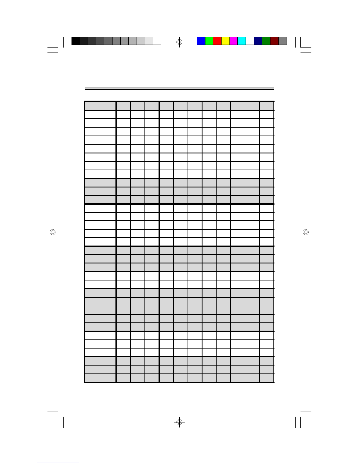
3.2 Jumper Settings
CPU BF0 BF1 BF2 JP9 JP10 JP15 VID0 VID1 VID2 VID3 VIO
P54C 75 OFF OFF OFF 1-2, 3-4 ON 1-2 ON ON ON ON OFF
P54C 90 OFF OFF OFF 3-4 ON 1-2 ON ON ON ON OFF
P54C 100 OFF OFF OFF 1-2 ON 1-2 ON ON ON ON OFF
P54C 120 ON OFF OFF 3-4 ON 1-2 ON ON ON ON OFF
P54C 133 ON OFF OFF 1-2 ON 1-2 ON ON ON ON OFF
P54C 150 ON ON OFF 3-4 ON 1-2 ON ON ON ON OFF
P54C 166 ON ON OFF 1-2 ON 1-2 ON ON ON ON OFF
P54C 200 OFF ON OFF 1-2 ON 1-2 ON ON ON ON OFF
P55C 166 ON ON OFF 1-2 ON 1-2 ON OFF OFF OFF ON
P55C 200 OFF ON OFF 1-2 ON 1-2 ON OFF OFF OFF ON
P55C 233 OFF OFF OFF 1-2 ON 1-2 ON OFF OFF OFF ON
K5 90 OFF OFF OFF 1-2 ON 1-2 ON ON ON ON OFF
K5 100 OFF OFF OFF 1-2 ON 1-2 ON ON ON ON OFF
K5 120 ON OFF OFF 3-4 ON 1-2 ON ON ON ON OFF
K5 133 ON OFF OFF 1-2 ON 1-2 ON ON ON ON OFF
K5 166 ON ON OFF 1-2 ON 1-2 ON ON ON ON OFF
K6 166 ON ON OFF 1-2 ON 1-2 ON OFF OFF ON ON
K6 200 OFF ON OFF 1-2 ON 1-2 ON OFF OFF ON ON
K6 233 OFF OFF OFF 1-2 ON 1-2 ON ON OFF OFF ON
IDT C6 150 (50x3) OFF ON OFF 1-2, 3-4 ON 1-2 ON ON OFF ON OFF
IDT C6 180 (60x3) OFF ON OFF 3-4 ON 1-2 ON ON OFF ON OFF
Cyrix PR120+ M1 ON OFF OFF 1-2, 3-4 ON 1-2 ON ON ON ON ON
Cyrix PR133+ M1 ON OFF OFF 1-2, 3-4 OFF 1-2 ON ON ON ON ON
Cyrix PR150+ M1 ON OFF OFF 3-4 ON 1-2 ON ON ON ON ON
Cyrix PR166+ M1 ON OFF OFF 1-2 ON 1-2 ON ON ON ON ON
Cyrix PR200+ M1 ON OFF OFF 3-4 OFF 1-2 ON ON ON ON ON
Cyrix PR150L M1 ON OFF OFF 3-4 ON 1-2 ON OFF OFF OFF ON
Cyrix PR166L M1 ON OFF OFF 1-2 ON 1-2 ON OFF OFF OFF ON
Cyrix PR200L M1 ON ON OFF 3-4 OFF 1-2 ON OFF OFF OFF ON
Cyrix PR166 M2 ON ON OFF 3-4 ON 1-2 ON OFF OFF OFF ON
Cyrix PR200 M2 ON ON OFF 1-2 ON 1-2 ON OFF OFF OFF ON
Cyrix PR233 M2 ON ON OFF 3-4 OFF 1-2 ON OFF OFF OFF ON
*Chips in the Cyrix “L” series are “Low Voltage” and operate at 2.8 volts.
10S1571 D1181-001 http://www.tyan.com
Resource Settings
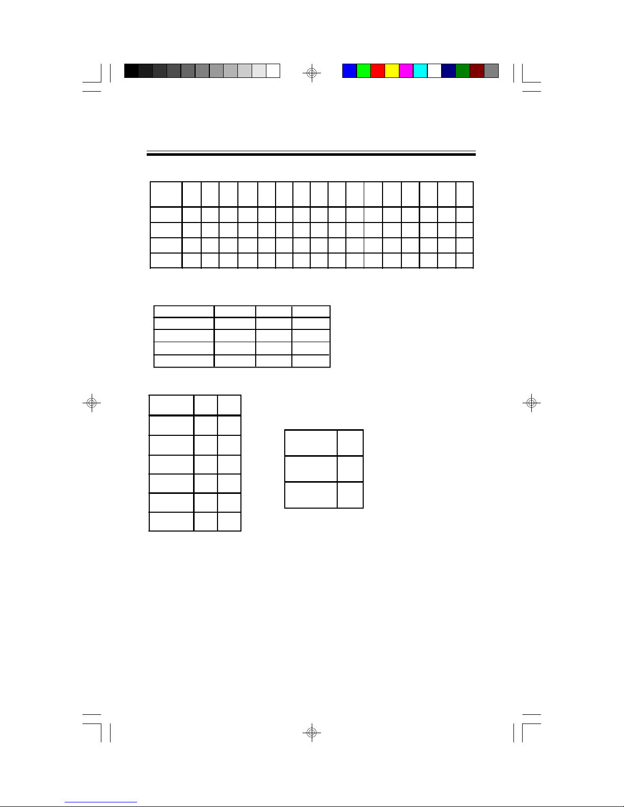
CPU Voltage Settings
CPU VCC 2.0V 2.1V 2.2V 2.3V 2.4V 2.5V 2.6V 2.7V 2.8V 2.9V 3.0V 3.1V 3.2V 3.3V 3.4V 3.5V
VID0
VID1
VID2
VID3
OFF OFF OFF OFF OFF OFF OFF OFF ON ON ON ON ON ON ON ON
OFF OFF OFF OFF ON ON ON ON OFF OFF OFF OFF ON ON ON ON
OFF OFF ON ON OFF OFF ON ON OFF OFF ON ON OFF OFF ON ON
OFF ON OFF ON OFF ON OFF ON OFF ON OFF ON OFF ON OFF ON
CPU Multipliers
CPU Mult BF0 BF1 BF2
x1.5 OFF OFF OFF
x2 ON OFF OFF
x2.5 ON ON OFF
x3 OFF ON OFF
BUS Speed Settings
BUS
Frequency
50 MHz
55 MHz
60 MHz 3-4 ON
66 MHz 1-2 ON
75 MHz 3-4 OFF
JP9 JP10
1-2,
ON
3-4
1-2,
OFF
3-4
BIOS Memory Voltage
Select
BIOS VCC JP23
5V 1-2
12V 2-3
83 MHz 1-2 OFF
Note: please ignore the JP21
label on the board.
WARNING:
This motherboard incorporates support for 75MHz and 83MHz BUS speeds.
However, these speeds will push PCI bandwidth beyond the Intel-recommended
specification for PCI 2.1 compliance. Therefore, TYAN Computer Corporation
takes no responsibility for any problems, hardware or software, related to the
use of BUS speeds beyond 66MHz. We also cannot guarantee any PCI cards’
compatibility beyond the specified speed of 33MHz. Technical support and
RMA/Warranty claims relating to the use of BUS speeds beyond the 66MHz/
33MHz limit recommended by Intel will not be honored by TYAN. Use at your
own risk.
11S1571 D1181-001 http://www.tyan.com

Resource Settings
Windows95 Users:
You may encounter problems with some of the devices in the Intel 82371AB
chipset. Neither the PCI Bridge nor the PCI Universal BUS device IDs for this
chipset (also called PIIX4) are recognized by Windows95. This is a software
problem, not a hardware problem, and can be easily remedied by either upgrading
to Windows98 or downloading the 82371AB patch found at http://www.tyan.com
or at ftp://download.intel.com/design/pcisets/busmastr/setupex.exe
SIMM DRAM Memory Voltage Select
DRAM VCC JP1 JP2 JP7 JP8
3V
5V
OFF OFF ON ON
ON ON OFF OFF
DIMM Memory Voltage Select
DIMM VCC JP3 JP4 JP5 JP6
3V
5V
OFF OFF ON ON
ON ON OFF OFF
Others
JP26 Install only if there is a speaker on board.
JP24 Connected to the LED for Turbo On/Off.
JP25 Connected to the switch for Turbo On/Off.
JP26 Pin 4 and 5 for Keylock function.
*Deturbo is not supported in 430TX chipset.
PS/2 Mouse Connector:
GND DATA VCC Keyboard
CLK
12S1571 D1181-001 http://www.tyan.com
I/O Port Setting: JP16 and JP17
JP16 JP17
For Serial Port 1-2 1-2
For IR Port 2-3 2-3
J17 Settings
pins function
3-4 EXTSM1
6-7 IR Receive
8-9 IR Transmit
13-14 IDE LED Primary
15-16 IDE LED Secondary
18-20 PWR LED
22-23 RST SW
24-27 SPK
3.3 CMOS RTC
Resource Settings
The TX chipset includes a Real Time Clock circuit. It provides the date and
the time for the system. Normally the life span of an RTC battery is 5 years.
If the battery for the RTC is low, it will prevent your system from
POSTing and you will not get a display. If this occurs, you will need to
replace the battery with another 3-volt lithium battery (Duracell DL2032).
3.4 Speaker Connector Installation
The S1571 provides a 4-pin header to connect the speaker. The speaker is
connected to pins 24-27 of jumper block J17.
3.5 Hardware Reset Switch Connector Installation
The RESET switch on your case's display panel provides users with the
HARDWARE RESET function, which is the same as power on/off. The
system will do a cold start after the RESET switch is pushed. The RESET
13S1571 D1181-001 http://www.tyan.com

Resource Settings
switch is a 2-pin connector and should be installed on pins 22 and 23 on
RESOURCE
jumper block J17.
SETTINGS
3.6 Flash EPROM-Jumper JP23
The S1571 uses flash memory to store BIOS programs. It can be updated
as new versions of the BIOS become available. The flash utility will guide
you through the process step by step.
JP23 determines which type of EPROM is used. This jumper has been set
to match the on-board BIOS chip. The factory default for the S1571 is on
pins 1 and 2. Depending on the type of EPROM used, some boards will
have JP23 on pins 2 and 3.
Refer to chapter 5 for Flash EPROM upgrade procedures.
3.7 Hardware CMOS & Password Reset: JP22
If you have been locked out of your system because you forgot your password or set the CMOS incorrectly, follow the instructions below.
a. Power off the system.
b. Connect jumper JP22 to pins 2 and 3.
c. Wait for 2 seconds, then return JP22 to pins 1 and 2.
d. Power on the system again.
By following the above procedures, you will erase your password and reset the CMOS to the BIOS defaults.
14S1571 D1181-001 http://www.tyan.com
Resource Settings
3.8 DRAM Installation
The S1571 uses a 64-bit data path from memory to CPU and can
accommodate up to 256MB of RAM. The mainboard supports Fast
Page Mode, and EDO (Extended Data Out) 72 pin SIMMs. SDRAMs
(Synchronous) are also supported in the DIMM slots. DIMMs must be of
the unbuffered variety. All installed memory will be automatically
detected so there is no need to set jumpers. The TX chipset can cache
up to 64MB of RAM.
wSIMM modules must be installed in pairs.
wEach pair of SIMMs must be of the same size and type.
wThe mainboard supports 1, 2, 4, 8, and 16MBx32 SIMM modules.
wSIMM banks 0, 1, and 2 can use either double- or single-sided SIMMs.
wTwo SIMMs or one unbuffered DIMM must be installed for the system
to POST.
wThe mainboard supports 1, 2 and 4MBx64 DIMM modules.
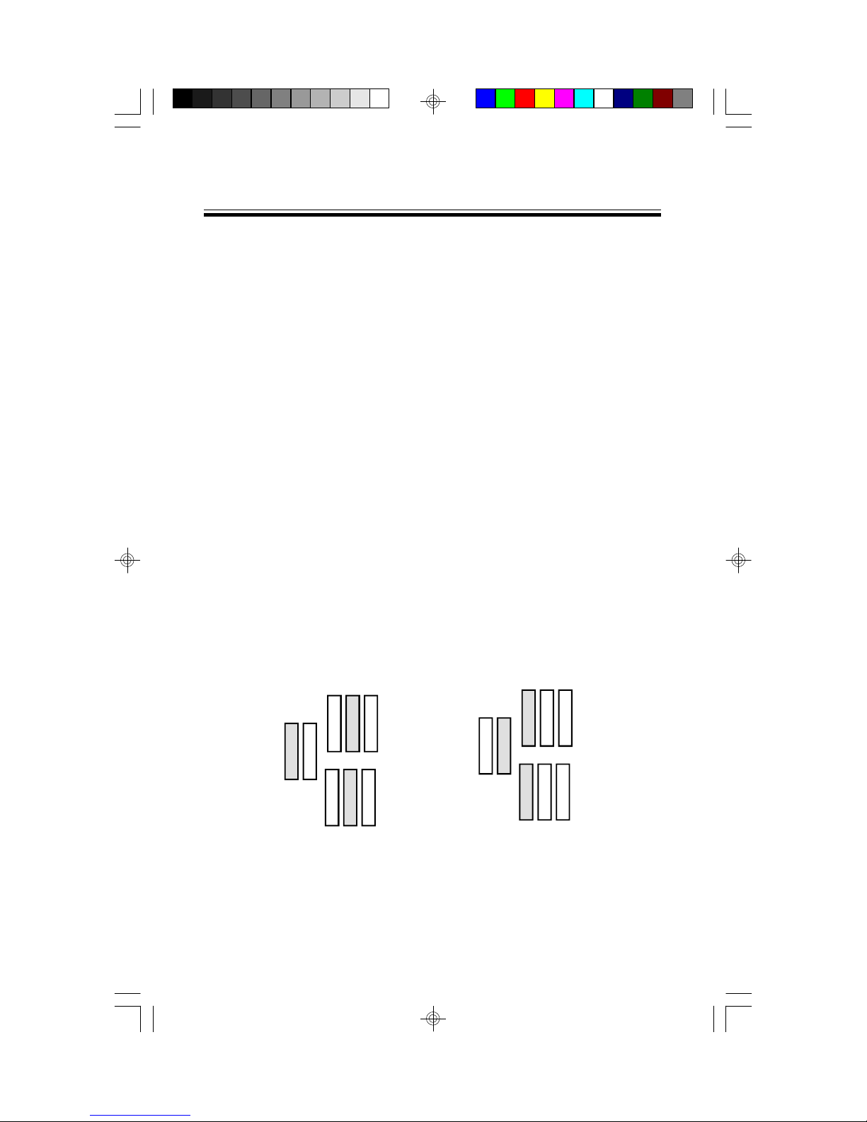
wSIMM bank 0 and DIMM bank 0 cannot be used at the same time.
wSIMM bank 1 and DIMM bank 1 cannot be used at the same time.
wYou can use SIMM bank 0 with DIMM bank 1.
wYou can use SIMM bank 1 with DIMM bank 0 (see figure below).
OK OK
The shaded boxes represent occupied slots.
15S1571 D1181-001 http://www.tyan.com
Resource Settings
wIf you use 4MBx64 DIMMs you cannot use DRAM bank 2. DRAM
bank 2 has an upper limit of 32MB.
wWe do not recommend using DRAM bank 2 along with DIMMs.
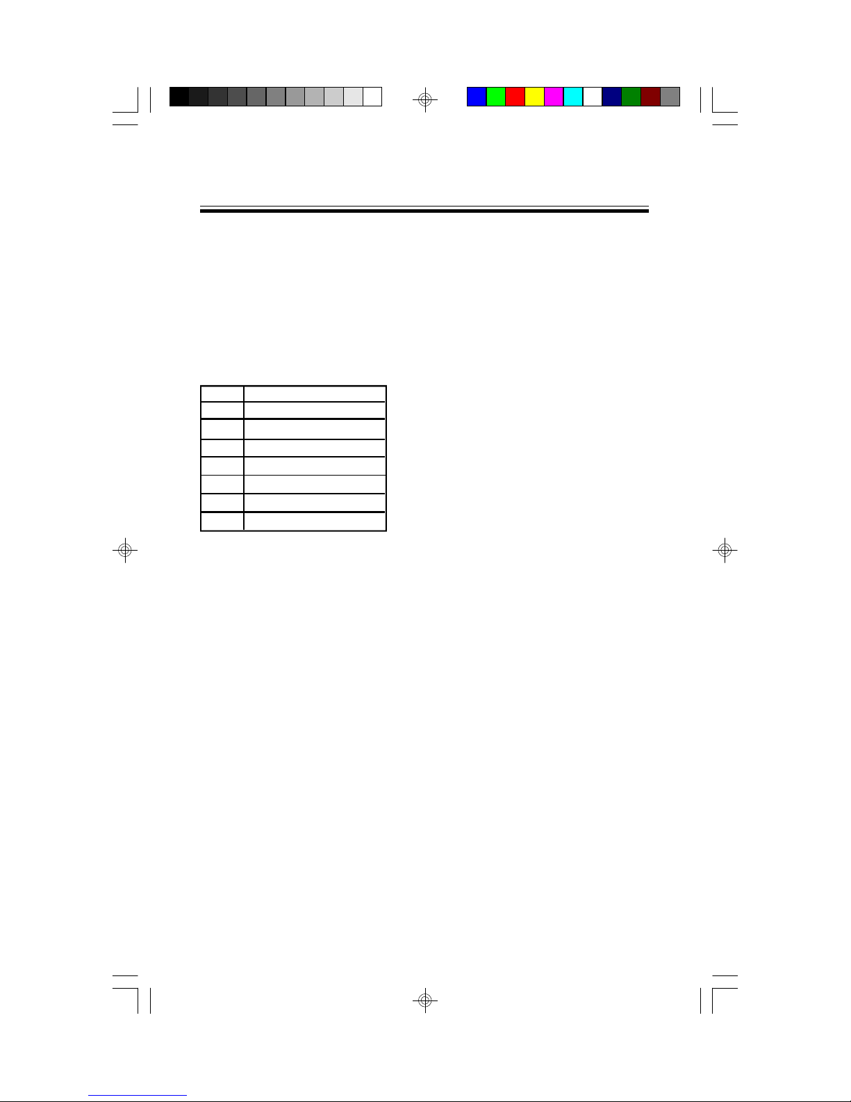
wThe following table shows some of the available memory configurations.
DRAM DRAM DRAM SDRAM SDRAM Total
Bank 0 Bank 1 Bank 2 Bank 0 Bank 1
4MBx2 none none none none 8MB
none none none 8MBx1 none 8MB
none none none 16MBx1 none 16MB
8MBx2 none none none none 16MB
4MBx2 4MBx2 4MBx2 none none 24MB
16MBx2 none none none none 32MB
none 8MBx2 none 16MBx1 none 32MB
32MBx2 none none none none 64MB
none none none none 64MBx1 64MB
none none none 32MBx1 64MBx1 96MB
none none none 64MBx1 64MBx1 128MB
64MBx2 none none none 64MBx1 192MB
none none none 128MBx1 128MBx1 256MB
3.9 CPU Installation
Several types of CPUs can be used on the S1571. Please refer to
section 3.2 for the correct CPU jumper settings for your board.
Remember:
w The CPU is a sensitive electronic component and it can be easily
damaged by static electricity. Do not touch the CPU pins with your
fingers.
w When installing the CPU into the socket, match the CPU pins to the
socket pins.
w Before the CPU is installed, the mainboard must be placed on a flat
surface. You should be able to insert the CPU with minimal pressure.
Do not push down hard, but do use firm pressure.
w A cooling fan and/or heat sink assembly is required to protect
the CPU from being damaged.
16S1571 D1181-001 http://www.tyan.com

Resource Settings
Installation procedure:
1. Make sure the ZIF socket lever is up. To raise the lever, pull it out
to the side a little and raise it as far as it will go. The top plate will
slide back.
2. Align the CPU and socket pin 1 corners. The pins on the bottom of
the CPU should align with the rows of holes in the socket.
3. Insert the CPU in the socket. It should insert easily. If it does not,
adjust the position of the lever a little.
4. Press the lever down. The top plate will slide forward. You will
feel some resistance as the pressure starts to secure the CPU in
the socket. This is normal and will not damage the CPU. The lever
should snap into place at the side of the socket.
3.10 Upgrading Cache Memory
The S1571 has 512KB of on-board pipeline-burst SRAM and cannot be
upgraded in the field. The TX chipset can cache a maximium of 64MB
of RAM.
3.11 Peripheral Device Installation
After all the jumpers on the mainboard have been set, it can then be mounted
into the case. Proceed to install the display card and any other peripheral
devices.
If a PCI-Bus interface card is to be installed in the system, any one of the
five PCI-Bus slots can support either a Master or a Slave device.
After installing the peripheral controllers, you should check everything
again, and prepare to power on the system.
17S1571 D1181-001 http://www.tyan.com
 Loading...