

Page 1

Thunder n6550EX
///
Version 1.1
S4989
Copyright
Copyright © MiTAC International Corporation, 2008. All rights reserved. No part
of this manual may be reproduced
or translated without prior written consent from MiTAC International Corporation.
Trademark
All registered and unregistered trademarks and company names contained in
this manual are property of their respective owners including, but not limited to
the following.
TYAN®, Thunder n6550EX are trademarks of MiTAC International Corporation.
AMD® ,Opteron™, and combinations thereof are trademarks of AMD
Corporation.
AMI®, AMIBIOS®, and combinations thereof are trademarks of AMI
Technologies.
Microsoft®, Windows® are trademarks of Microsoft Corporation.
Nvidia® and nForce® are trademarks of Nvidia Corporation.
IBM®, PC®, AT®, PS/2® are trademarks of IBM Corporation.
Winbond® is a trademark of Winbond Electronics Corporation.
Notice
Information contained in this document is furnished by MiTAC International
Corporation and has been reviewed for accuracy and reliability prior to printing.
MiTAC assumes no liability whatsoever, and disclaims any express or implied
warranty, relating to sale and/or use of TYAN
warranties relating to fitness for a particular purpose or merchantability. MiTAC
retains the right to make changes to product descriptions and/or specifications
at any time, without notice. In no event will MiTAC be held liable for any direct
or indirect, incidental or consequential damage, loss of use, loss of data or other
malady resulting from errors or inaccuracies of information contained in this
document.
®
products including liability or
Page 2

Page 3

Contents
Before you begin Ⅴ
Chapter 1: Instruction 1
1.1 Congratulations .......................................................................................1
1.2 Hardware Specifications.......................................................................... 1
1.3 Software Specifications ...........................................................................2
Chapter 2: Board Installation 3
2.1 Board Image ............................................................................................ 4
2.2 Block Diagram ......................................................................................... 5
2.3 Board Parts, Jumpers and Connectors.................................................... 6
2.4 Installing the Processor .........................................................................16
2.5 Heat sink Installation .............................................................................17
2.6 Thermal Interface Material..................................................................... 18
2.7 Finishing Installing the Heat sink ...........................................................19
2.8 Tips on Installing Motherboard in Chassis ............................................. 20
2.9 Installing the Memory ............................................................................23
2.10 Attaching Drive Cables ........................................................................ 26
2.11 Installing Add-In Cards ........................................................................27
2.12 Connecting External Devices............................................................... 28
2.13 Installing the Power Supply .................................................................29
2.14 Finishing Up.........................................................................................30
Chapter 3: KVM-over-IP Server Management 31
3.1 Overview of KVM-over-IP Sever Management..................................... 31
3.2 Key Feature.......................................................................................... 31
3.3 Initialize and Web Interface ..................................................................32
3.4 Configuration ........................................................................................ 35
3.5 Menu Option ......................................................................................... 42
3.6 Notes ....................................................................................................78
Chapter 4: BIOS Setup 83
3.1 About the BIOS..................................................................................... 83
3.2 BIOS Menu Bar ....................................................................................83
3.3 Setup Basics......................................................................................... 84
3.4 Getting Help..........................................................................................84
3.5 In Case of Problems ............................................................................. 84
3.6 BIOS Main Menu .................................................................................. 85
3.7 BIOS Advanced Menu .......................................................................... 86
3.8 PCI PnP Menu....................................................................................106
3.9 Boot Menu .......................................................................................... 108
3.10 Security Menu.................................................................................... 113
3.11 Chipset Menu ....................................................................................114
3.12 Exit Menu........................................................................................... 127
Page 4

Chapter 5: Diagnostics 129
4.1 Beep Codes......................................................................................... 129
4.2 Flash Utility .......................................................................................... 129
4.3 AMIBIOS Post Code............................................................................130
Appendix: How to Make a Driver Diskette 133
Glossary 135
Technical Support 141
Page 5
Before you begin…
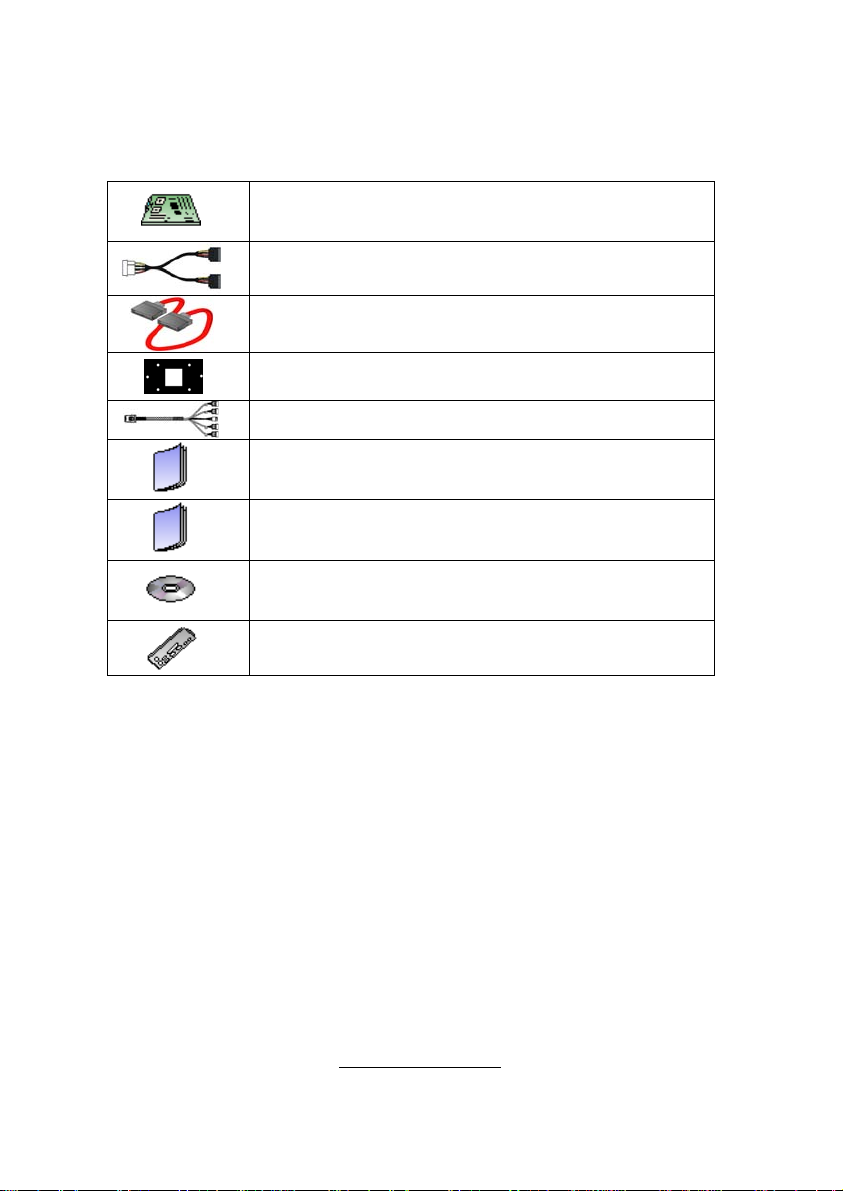
Check the box contents!
The retail motherboard package should contain the following:
1x S4989 Motherboard
3 x SATA Power Cable
6 x SATA Cable
4 x CPU Backplane
2 x SAS to Backplane Cable
1 x S4989 User’s Manual
1 x S4989 Quick Reference Guide
®
1 x TYAN
Driver CD
1 x I/O Shield
If any of these items are missing, please contact your vendor/dealer for
replacement before continuing with the installation process.
V
http://www.tyan.com
Page 6

VII
http://www.tyan.com
Page 7

Chapter 1: Instruction
1.1 - Congratulations
You have purchased one of the most powerful server solutions. Based on
Nvidia® NPF3600 and NPF3050 chipsets, the Thunder n6650EX (S4989) is
designed to support AMD
®
Opteron™ Rev. F 8000 series Dual-core and Quadcore processors and up to 128GB DDRII-400/533/667/800 memory, providing a
rich feature set and incredible performance. Leveraging advanced technology
from AMD
®
, the Thunder n6650EX (S4989) is capable of offering scalable 32
and 64-bit computing, high-bandwidth memory design, and lightning-fast PCI-E,
PCI-X bus implementation.
The Thunder n6650EX (S4989) not only empowers your company in today’s
demanding IT environment but also offers a smooth path for future application
usage. TYAN® is also proud to deliver the Thunder n6650EX (S4989) in SAS
and SATA II flavor. All of this provides the Thunder n6650EX (S4989) the power
and flexibility to meet the needs of nearly any server application.
Remember to visit TYAN®’s Website at http://www.tyan.com. There you can find
information on all of TYAN
®
’s products with FAQs, online manuals and BIOS
upgrades.
1.2 - Hardware Specifications
Processors
● Four 1207-pin ZIF socket
● Supports up to four AMD®
Opteron™ Rev. F 8000 series
Dual Core/ Quad-core processors
● Up to 1.0GHz Hyper-Transport
link support
● Four onboard 5-phase VRDs (four
phases for CPU-core and one
phase for North bridge)
Chipset
● nVidia
● PERICOM
● PERICOM
®
nForce® Pro 3600+
®
nVidia
nForce® Pro 3050
®
bridge
®
PI7C9X130 PCI-E
PI2PCIE412-D SLI
switch
● HW monitors:
(1) WinbondW83793G
(2) ADT7476
Expansion Slots
● (2) PCI-E slots with x16 signal
(1) x 16 signal from MCP55
(1) x 8 or x16 signal (through
PCI-E switch) from IO55
● (2) PCI-E slots with x8 signal from
IO55
● (2) PCI-X 133MHz slots from
PERICOM PI7C9X130
(through IO55)
System Management
● KVM-over-IP server management
on board (M3 type)
Onboard SAS Controller
● LSI 1068E SAS controller
● (8) SAS ports
● RAID 0,1,1E support
1
http://www.tyan.com
Page 8

Memory
● Dual-channel memory bus
● 32 x 240-pin 1.8-volt DDRII DIMM
sockets (eight on each CPU)
● Maximum of 128GB DDRII-
400/533/667/800
● Supports ECC Registered DIMMs
Integrated I/O
● (2) USB headers (two ports in one
header)
● (6) SATAII connectors from
MCP55 (one is for CD-ROM)
● (8) SAS ports (2 four-in-one
connectors) from LSI 1068E
● (2) RJ-45 10/100/1000 LAN ports
from 82571
(1) RJ-45 10/100 LAN port from
onboard KVM-OVER-IP server
management
● (10) 4-pin FAN headers with
autofan and tachmeter function
● (1) 2x9-pin front panel header
● (1) 2x7-pin TYFP2 header
● (1) 2x9-pin FAN header for
Barebone
● (1) 2x3-pin LCM header
Back Panel I/O Connector
● Stacked connector for PS/2
®
keyboard and mouse
● Stacked connector for (2) USB 2.0
● Stacked connector for VGA+COM
●(3) RJ-45 connectors, side by side
Integrated Network Processor
● GbE Intel 82571 (2x GbE ports)
● Davicom DM9161AE (PHY) for
onboard KVM-over-IP server
management (LAN3 MAC is
integrated in KIRA100)
● WOL and PXE support
● (3) RJ-45 ports with LEDs
Integrated 2D PCI Graphics
● XGI Z9S
● PCI interface
● 32MB DDRII frame buffer
memory
BIOS
● AMIBIOS
ROM
®
on 8Mbit LPC Flash
Form Factor
● SSI / Extend ATX(13”x 16.2”)
● PCB layer:10-layer
Power
● EPS12V
● (1) 24-pin,3V+5V+12V power
connector
● (2) 8-pin,12V power connector
● (1) 4-pin,12V power connector
Regulatory
● FCC Class B (DoC)
● European Community CE (DoC)
1.3 - Software Specifications
For OS (operation system) support, please check with Tyan support for latest
information.
2
http://www.tyan.com
Page 9

Chapter 2: Board Installation
You are now ready to install your motherboard.
How to install our products right… the first time
The first thing you should do is reading this user’s manual. It contains important
information that will make configuration and setup much easier. Here are some
precautions you should take when installing your motherboard:
(1) Ground yourself properly before removing your motherboard from the
antistatic bag. Unplug the power from your computer power supply and
then touch a safely grounded object to release static charge (i.e. power
supply case). For the safest conditions, TYAN® recommends wearing
a static safety wrist strap.
(2) Hold the motherboard by its edges and do not touch the bottom of the
board, or flex the board in any way.
(3) Avoid touching the motherboard components, IC chips, connectors,
memory modules, and leads.
(4) Place the motherboard on a grounded antistatic surface or on the
antistatic bag that the board was shipped in.
(5) Inspect the board for damage.
The following pages include details on how to install your motherboard into your
chassis, as well as installing the processor, memory, disk drives and cables.
NOTE
DO NOT APPLY POWER TO THE BOARD IF IT HAS BEEN
DAMAGED.
3
http://www.tyan.com
Page 10
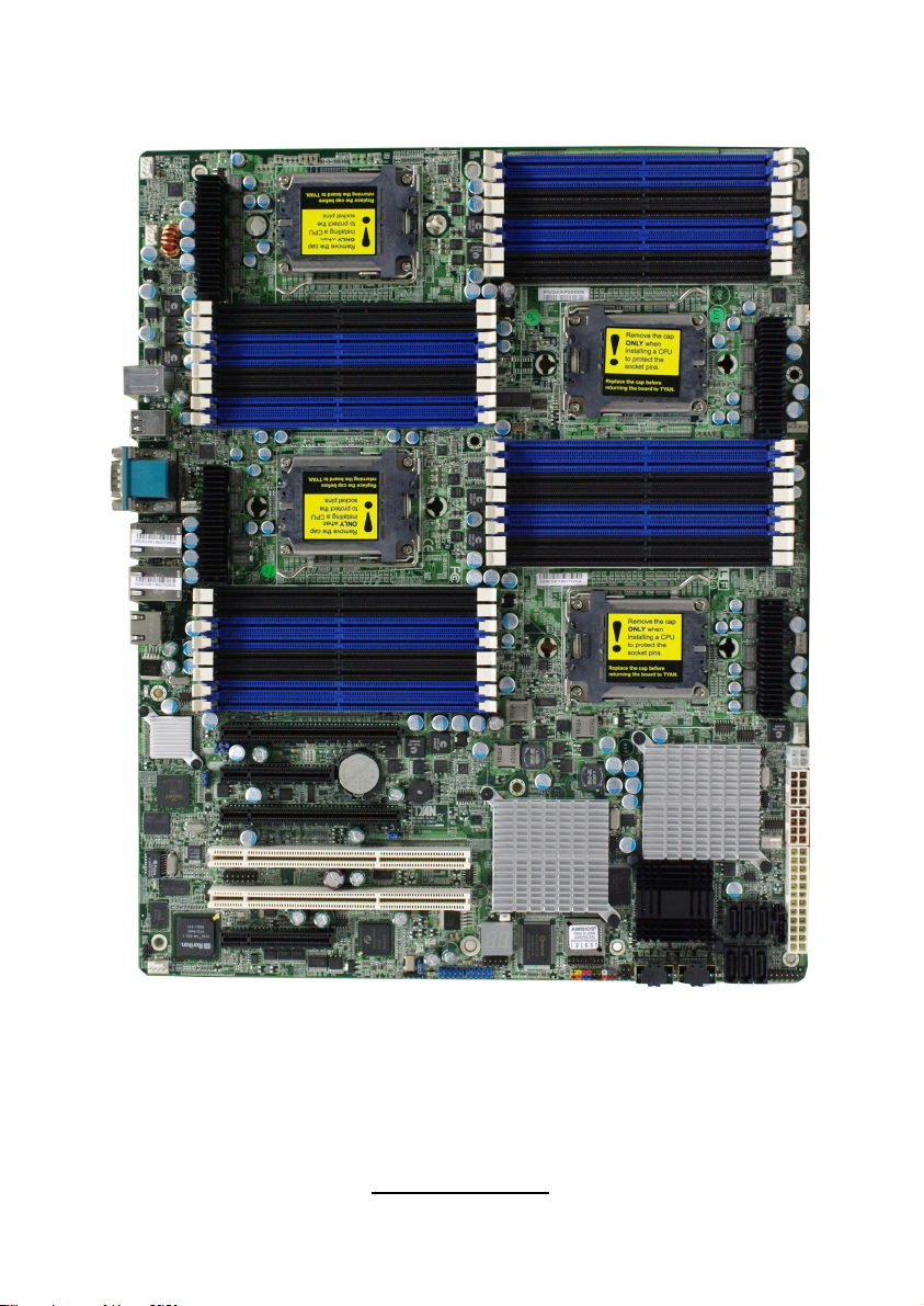
2.1- Board Image
This picture is representative of the latest board revision available at
the time of publishing. The board you receive may or may not look
exactly like the above picture.
4
http://www.tyan.com
Page 11
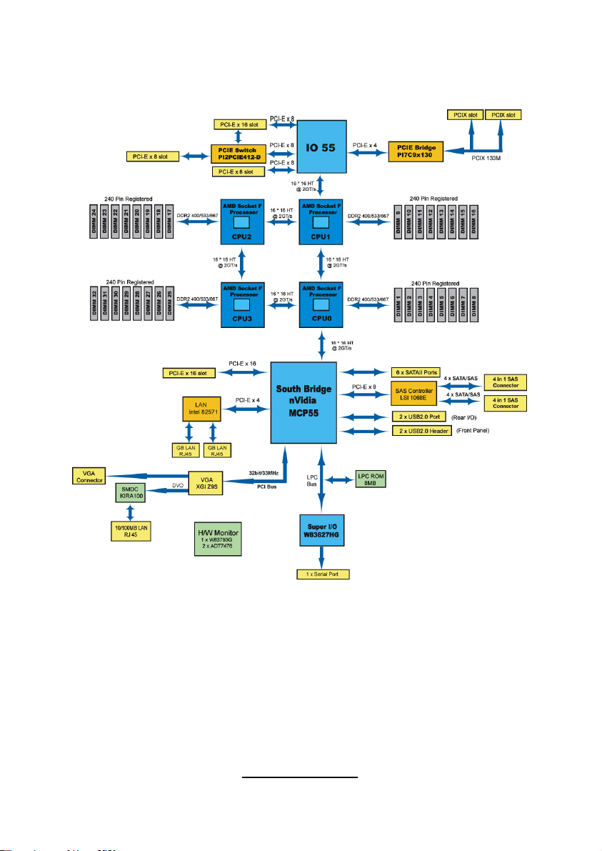
2.2 - Block Diagram
Thunder n6650EX (S4989) Block Diagram
5
http://www.tyan.com
Page 12
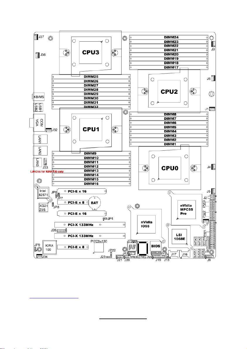
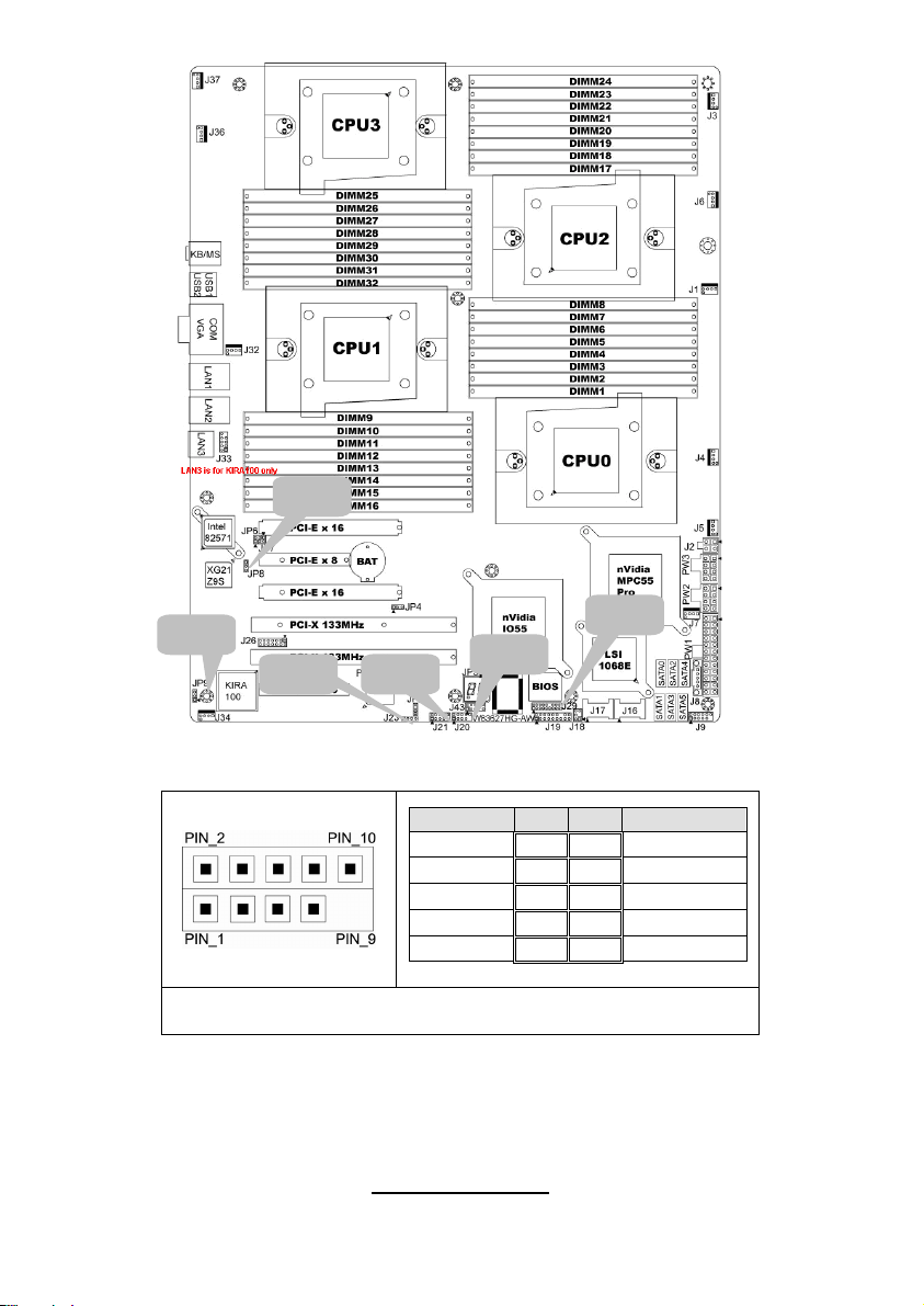
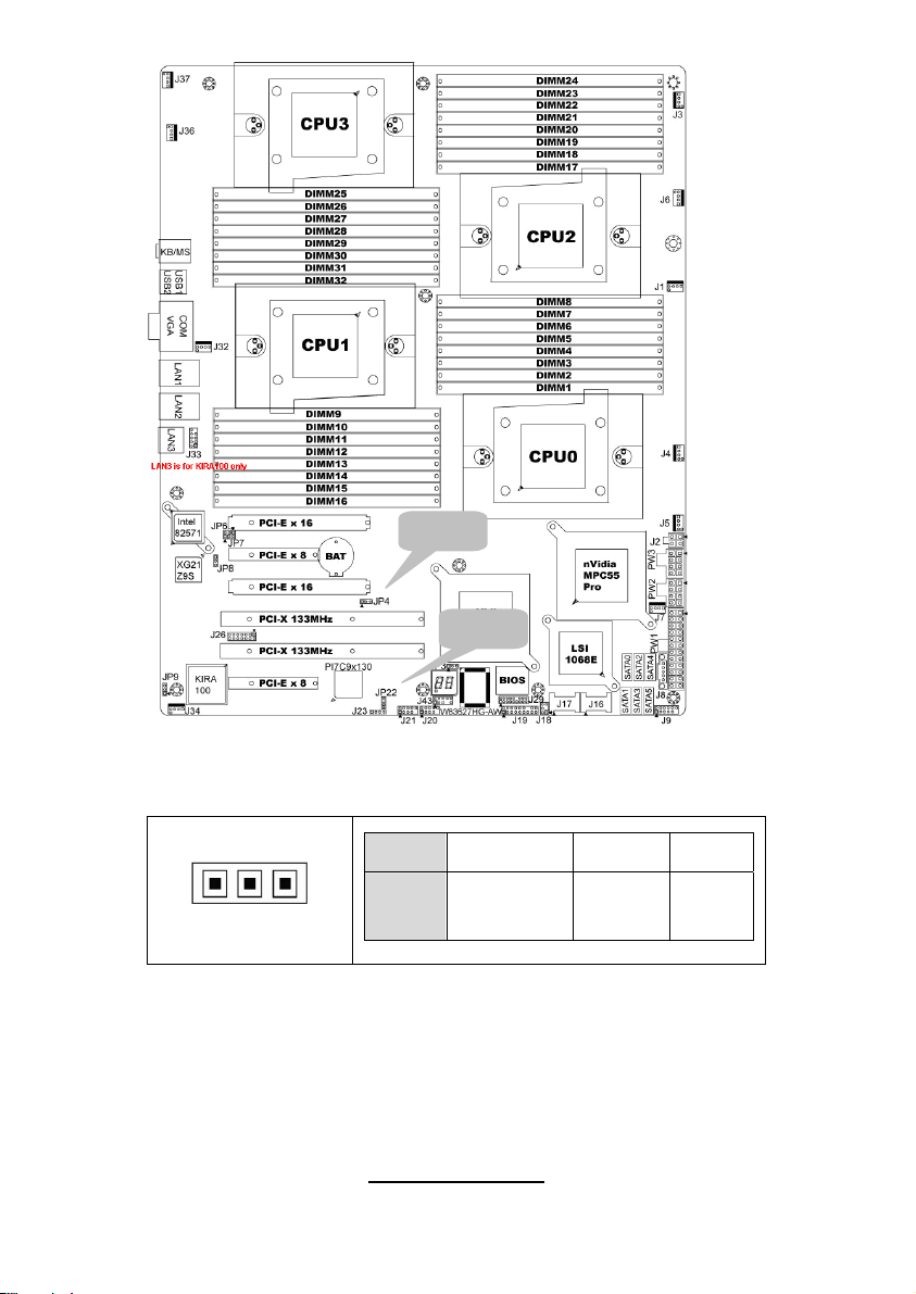
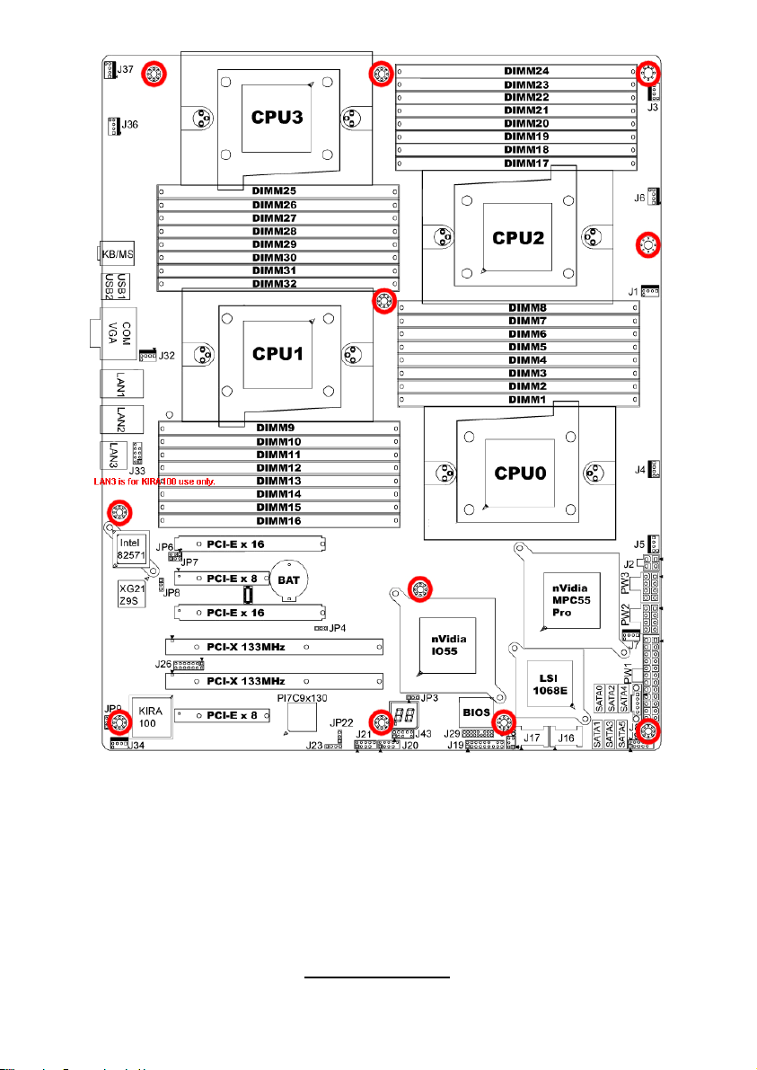
2.3 - Board Parts, Jumpers and Connectors
This diagram is representative of the latest board revision available at the time
of publishing. The board you receive may not look exactly like the above
diagram. But for the DIMM number please refer to the above placement for
memory installation. For the latest board revision, please visit:
http: //www.tyan.com
6
http://www.tyan.com
Page 13
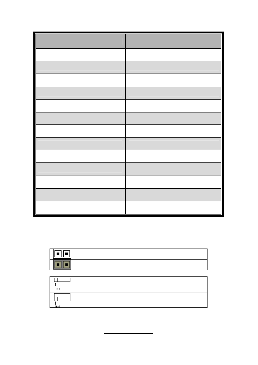
Jumpers & Connectors
Jumper/Connector Function
J1/J3/J4/J5/J6/J7/J32/J34/J36/J37 Fan connector
J8 PSMI Header
J9
J18 LCM Header
J19 Front Panel Header
J20/J21 USB 2.0 Header
J23 PCI-X Mode Selection
J29 BBU Fan Connector
JP3 Clear CMOS
JP8
JP9 IPMB Pin Header
JP4 PCI-E configuration selection
JP22
Jumper Legend
OPEN - Jumper OFF Without jumper cover
CLOSED - Jumper ON With jumper cover
Front Panel Header for
Barebones System
XG21 VGA Enable/Disable
Jumper
PCI-X clock frequency 133/100
MHz selection
To indicate the location of pin-1
To indicate the location of pin-1
7
http://www.tyan.com
Page 14
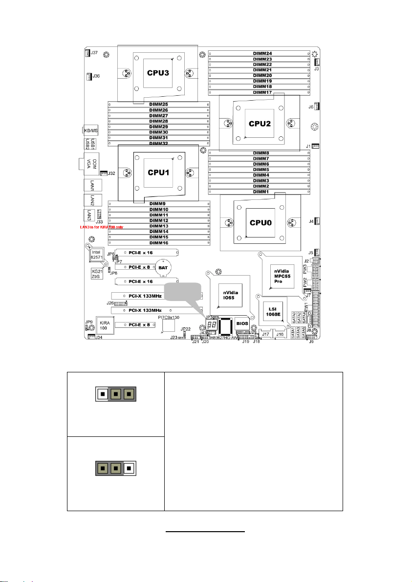
Jumper Placement
JP3
JP3: Clear CMOS
Pin_3 Pin_1
Pin_3 Pin_1
Clear CMOS
Normal
(Default)
You can reset the CMOS settings by using
this jumper if you have forgotten your
system/setup password or need to clear
system BIOS setting.
- Power off system and disconnect
both power connectors from the
motherboard
- Put jumper cap back to Pin_1 and
Pin_2 (default setting)
- Use jumper cap to close Pin_2 and
Pin_3 for several seconds to Clear
CMOS
Reconnect power & power on system
8
http://www.tyan.com
Page 15
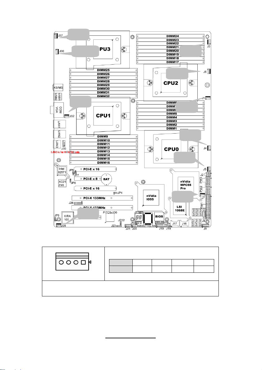
J37
J36
J32
J34
J1/J3/J4/J5/J6/J7/J32/J34/J36/J37: 4-pin fan connector
Pin 1 2 3 4
Pin_1
Signal
GND +12V TACH PWM
J3
J6
J1
J4
J5
J7
NOTE: When using the 3-pin fans, you will have no auto fan
functionality.
9
http://www.tyan.com
Page 16
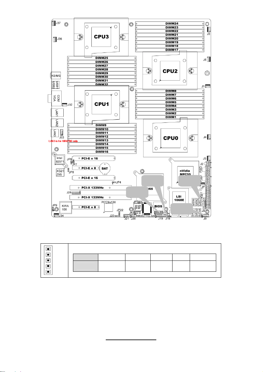
J8: PSMI Header
Pin_1
J8J18
J19
J9
Pin 1 2 3 4 5
Signal
SMBUS
CLOCK
SMBUS
DATA
RSVD
(NC)
GND VDD_3P
3_DUAL
10
http://www.tyan.com
Page 17
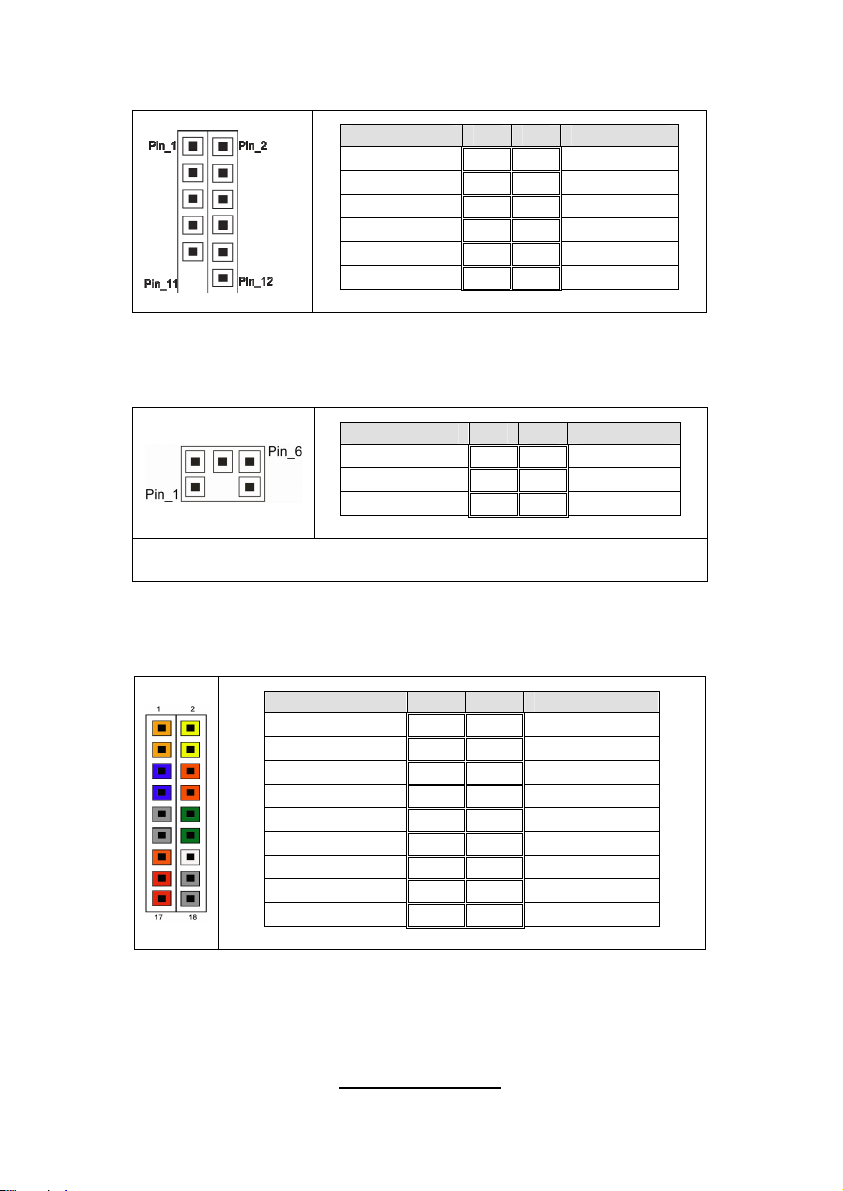
J9: Front panel Header for Barebones Systems
Signal Pin Pin Signal
LAN1_LED+ 1 2 LAN1_LEDLAN2_LED+ 3 4 LAN2_LEDLAN3_LED+ 5 6 LAN3_LED-
ID_LED+ 7 8 ID_LEDID_S/W+ 9 10 ID_S/W-
Key 11 12 RSVD
J18: LCM Pin Header
Signal Pin Pin Signal
VCC_5_RUN 1 2 RXD
KEY PIN 3 4 GND
VCC_5_ALW 5 6 TXD
Use this header to connect to the LCM module with system
monitoring function.
J19: Front Panel Header Connector
Signal Pin Pin Signal
HD LED+ 1 2 PW_LED+
HD_LED- 3 4 PW LED-
GND 5 6 P_S/W
RESET 7 8 GND
GND 9 10 FANFAIL_H
EXT_NMI 11 12 FANFAIL_L
5VSB 13 14 Key
SDA 15 16 GND
SCL 17 18 INTRUDER_L
11
http://www.tyan.com
Page 18
JP8
JP9
J29
J20
J21J23
J20/J21: USB Pin Header
Signal Pin Pin Signal
+5VPWR 1 2 +5VPWR
USB0- 3 4 USB1-
USB0+ 5 6 USB1+
GND 7 8 GND
KEY PIN 9 10 GND
Use this header to connect to the USB devices via the provided
USB cable.
12
http://www.tyan.com
Page 19
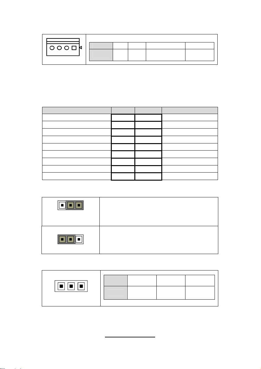
J23: PCI-X Mode Selection Header
Pin 1 2 3 4
Pin_1
Signal
N/C GND PCI_PCIXCAP
PCI Mode = Short 2-3
PCI-X 66Mhz = Short 3-4
PCI-X 100/133Mhz = 1-2 (Default)
J29: BBU Fan Connector
Signal Pin Pin Signal
SYS1_TACH 1 2 SYS6_TACH
SYS2_TACH 3 4 SYS7_TACH
SYS3_TACH 5 6 SYS8_TACH
SYS4_TACH 7 8 SYS9_TACH
SYS5_TACH 9 10 SYS10_TACH
GND 11 12 KEY PIN
SYS2_PWM 13 14 CPUX_PWM
SYS11_TACH 15 16 SYS13_TACH
SYS12_TACH 17 18 SYS14_TACH
JP8: XG21 VGA Enable/Disable Jumper
10k TO
GROUND
Pin_3 Pin_1
Normal
(Default)
Pin_3 Pin_1
JP9: IPMB Pin Header
Pin_1
Pin_1 & Pin_2 closed: default setting
Pin_2 & Pin_3 closed: disable XG21
Pin 1 2 3
Signal
IPMB
DATA
GND
IPMB
CLK
13
http://www.tyan.com
Page 20
JP4
JP22
JP4: PCI-E Configuration Selection
Pin 1 2 3
Pin_1
Signal
DETECT_L
14
http://www.tyan.com
PCIEX16
PEMOD
IO55
NC
SEL_L
Page 21

JP22: PCI-X Clock Frequency 133/100 MHz Selection
Pin 1 2 3
Pin_1
Signal
1k to
GND
S_SEL100
1k to
3.3V
15
http://www.tyan.com
Page 22
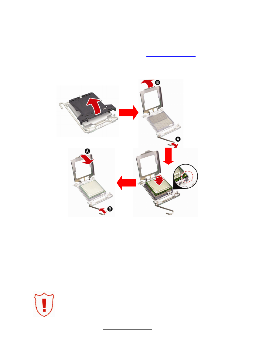
2.4 - Installing the Processor
Your brand new Thunder n6650EX (S4989) supports the latest 64-bit processor
technology from AMD®. Only AMD® Opteron™ Rev. F 8000 series processors
are certified and supported with this motherboard.
Check our website for latest processor support. http://www.tyan.com
®
is not liable for damage as a result of operating an unsupported
TYAN
configuration.
The diagram is provided as a visual guide to help you install the socket
processor and may not be an exact representation of the processor you have.
Step 1: Take off the CPU protection cap.
Step 2: Pull the CPU lever up to unlock the CPU socket (A). Then open the
socket in the direction as shown (B).
Step 3: Place the CPU on the CPU socket, ensuring that pin 1 is located in the
right direction.
Step 4: Close the CPU socket cover (A) and press the CPU socket lever down
to secure the CPU (B).
Take care when installing the processor as it has very fragile
connector pins below the processor and can bend and break
if inserted improperly.
16
http://www.tyan.com
Page 23

2.5 - Heat sink Installation
After installing the processor, you should proceed to install the heat sink. The
CPU heat sink will ensure that the processor do not overheat and continue to
operate at maximum performance for as long as you own them. The overheated
processor is dangerous to the motherboard.
For the safest method of installation and information on choosing the
appropriate heat sink, use heat sinks validated by AMD. Please refer to AMD’s
website at http://www.amd.com.
The following diagram illustrates how to install heat sink onto the CPU of S4989.
Place the heat sink on top of the CPU
and secure it to the motherboard using
two screws clockwise.
17
http://www.tyan.com
Page 24
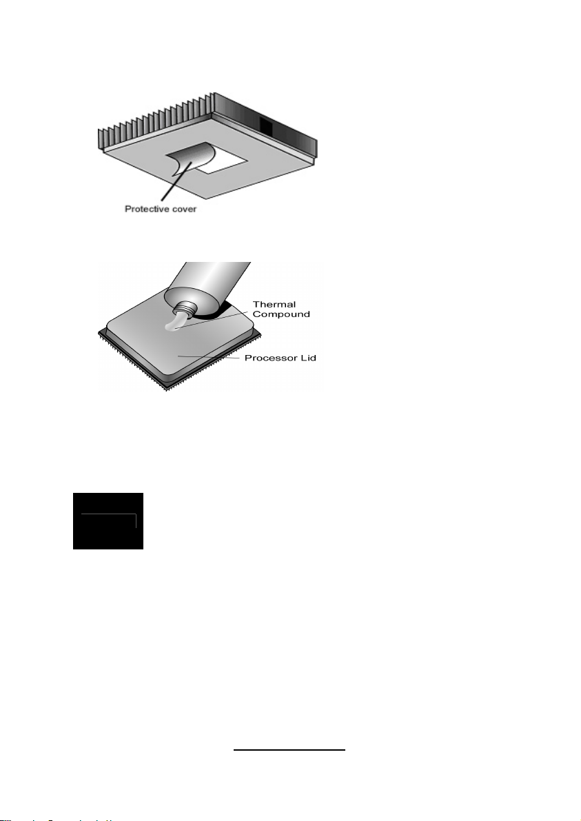
2.6 - Thermal Interface Material
Always check with the manufacturer of the heat sink &
NOTE
processor to ensure the Thermal Interface material is
compatible with the processor & meets the manufacturer’s
warranty requirements
There are two types of
thermal interface materials
designed for use with the
AMD® Opteron™
processors.
The most common material
comes as a small pad
attached to the heat sink at
the time of purchase. There
should be a protective cover
over the material. Take care
not to touch this material.
Simply remove the protective
cover and place the heat
sink on the processor.
The second type of interface
material is usually packaged
separately. It is commonly
referred to as ‘thermal
compound’. Simply apply a
thin layer on to the CPU lid
(applying too much will
actually reduce the cooling).
18
http://www.tyan.com
Page 25

2.7 - Finishing Installing the Heat sink
After you have finished installing the heat sink onto the processor and
socket, attach the end wire of the fan (which should already be attached to
the heat sink) to the motherboard. The following diagram illustrates how to
connect fans onto the motherboard.
Once you have finished installing all the fans you can connect your drives
(hard drives, CD-ROM drives, etc.) to your motherboard.
19
http://www.tyan.com
Page 26

2.8 - Tips on Installing Motherboard in Chassis
Before installing your motherboard, make sure your chassis has the
necessary motherboard support studs installed. These studs are usually
metal and are gold in color. Usually, the chassis manufacturer will pre-install
the support studs. If you are unsure of stud placement, simply lay the
motherboard inside the chassis and align the screw holes of the
motherboard to the studs inside the case. If there are any studs missing,
you will know right away since the motherboard will not be able to be
securely installed.
20
http://www.tyan.com
Page 27
21
http://www.tyan.com
Page 28
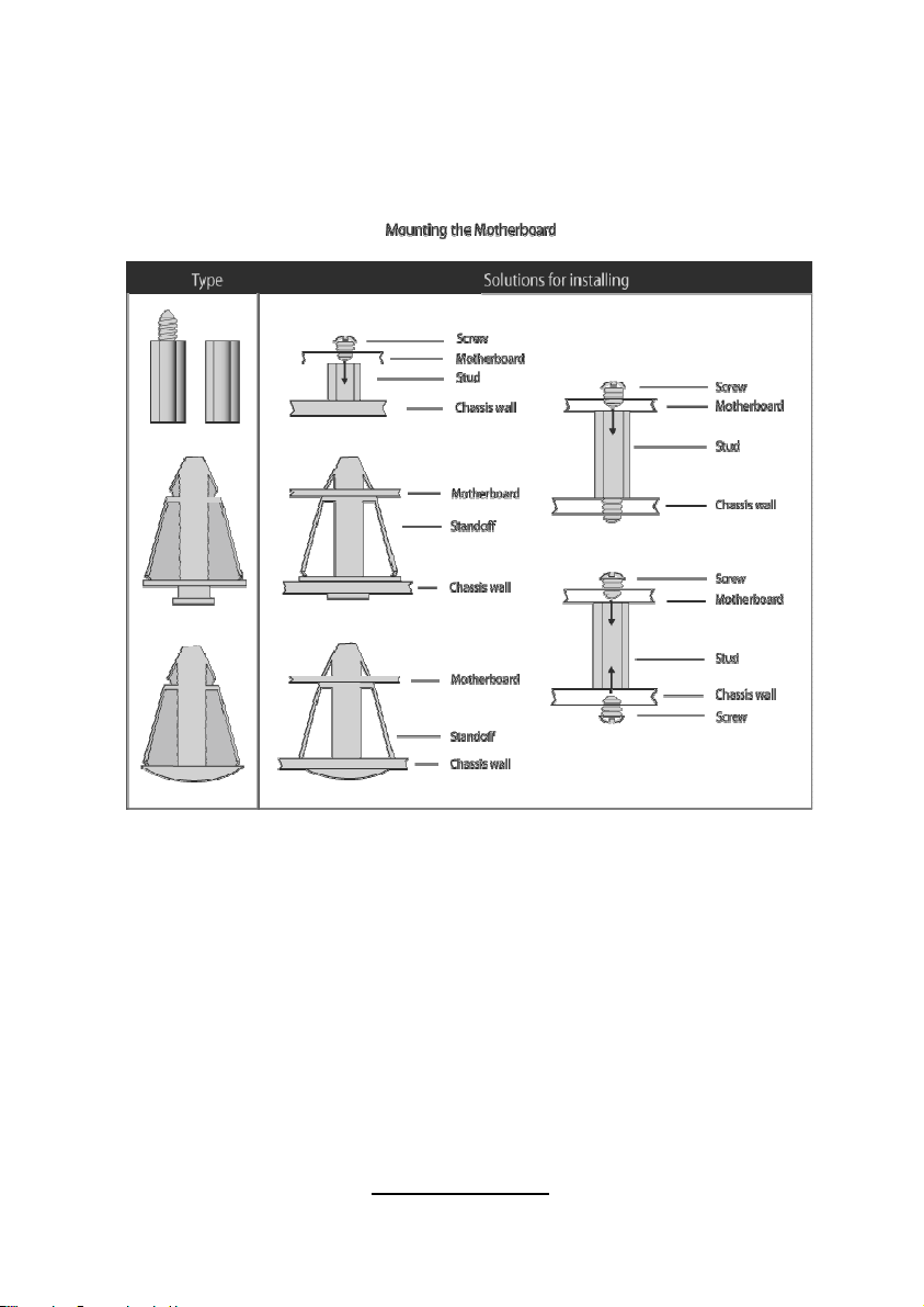
Some chassis’ include plastic studs instead of metal. Although the plastic
studs are usable, TYAN® recommends using metal studs with screws that
will fasten the motherboard more securely in place.
Below is a chart detailing what the most common motherboard studs look
like and how they should be installed
.
22
http://www.tyan.com
Page 29
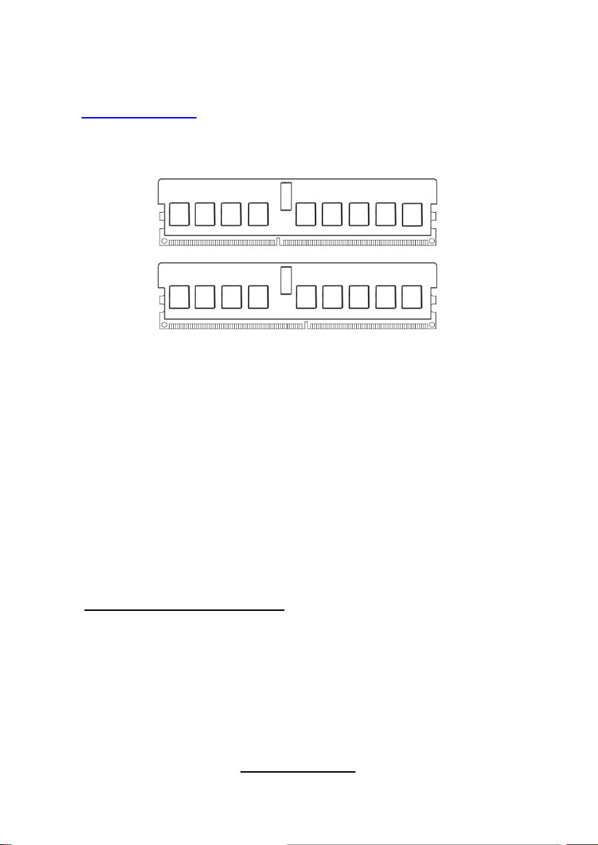
2.9 - Installing the Memory
Before installing memory, ensure that the memory you have is compatible
with the motherboard and processor. Check the TYAN® Web site at:
http://www.tyan.com
your motherboard.
The following diagram shows common types of DDR2 memory modules.
for details of the type of memory recommended for
• AMD Opteron™ processors support 64bit (non-interleaved) or 128bit
(interleaved) memory configuration.
• ECC Registered DDRII-400/533/667/800 memory modules are
supported.
• All installed memory will automatically be detected and no jumpers or
settings need changing.
• The Thunder n6650EX (S4989) supports up to 128GB of memory.
NOTE:
1). Refer to the memory population option table for detailed memory
configuration instruction.
2). For the DIMM number please refer to the motherboard placement in “2.3 Board Parts, Jumpers and Connectors” for memory installation.
Memory Population Option Table
To correctly install the memory in pairs (DIMMA# + DIMMB#), refer to the
table for supported population options. Start installing Memory modules
from DIMM7 and DIMM8.
23
http://www.tyan.com
Page 30

Single CPU
Quantity of
memory installed
CPU0_DIMM1(A) √ √ √
CPU0_DIMM2(B) √ √ √
CPU0_DIMM3(A) √ √ √
CPU0_DIMM4(B) √ √ √
CPU0_DIMM5(A) √ √ √ √ √ √
CPU0_DIMM6(B) √ √ √ √ √ √
CPU0_DIMM7(A) √ √ √ √ √ √ √ √ √
CPU0_DIMM8(B) √ √ √ √ √ √ √ √ √
CPU1_DIMM9(A) √ √
CPU1_DIMM10(B) √ √
CPU1_DIMM11(A) √ √
CPU1_DIMM12(B) √ √
CPU1_DIMM13(A) √ √ √ √
CPU1_DIMM14(B) √ √ √ √
CPU1_DIMM15(A) √ √ √ √ √ √
CPU1_DIMM16(B) √ √ √ √ √ √
CPU2_DIMM17(A) √
CPU2_DIMM18(B) √
CPU2_DIMM19(A) √
CPU2_DIMM20(B) √
CPU2_DIMM21(A) √ √
CPU2_DIMM22(B) √ √
CPU2_DIMM23(A) √ √ √
CPU2_DIMM24(B) √ √ √
CPU3_DIMM25(A) √
CPU3_DIMM26(B) √
CPU3_DIMM27(A) √
CPU3_DIMM28(B) √
CPU3_DIMM29(A) √ √
CPU3_DIMM30(B) √ √
CPU3_DIMM31(A) √ √ √
CPU3_DIMM32(B) √ √ √
Installed
(CPU0 only)
2 4 8 4 8 16 8 16 32
Dual CPU
installed
(CPU0 and
CPU1)
Four CPU
installed
Note:
1.” √ ” indicates a populated DIMM slot.
2. We strong recommend that install memory in pairs.
3. Please always install memory from the furthest A channel DIMM slot.
24
http://www.tyan.com
Page 31

Memory Installation Procedure
Follow these instructions to install memory modules into the Thunder n6650EX.
1. Press the locking levers in the direction shown in the following illustration.
2. Align the memory module with the socket. The memory module is keyed
to fit only one way in the socket.
Key slot
3. Seat the module firmly into the socket by gently pressing down until it sits
flush with the socket. The locking levers pop up into place.
25
http://www.tyan.com
Page 32

2.10 - Attaching Drive Cables
Attaching Serial ATA Cables
The Thunder n6650EX (S4989) is equipped with 6 Serial ATA (SATA)
channels. Connections for the drives are very simple.
There is no need to set Master/Slave jumpers on SATA drives.
Please refer to FRU List for the related cables. If you are in need of
SATA/SAS cables or power adapters please contact your place of purchase.
The following pictures illustrate how to connect an SATA drive
1. SATA drive cable
connection
2. SATA drive power
connection
3. SATA cable motherboard
connector
4. SATA drive power adapter
26
http://www.tyan.com
Page 33

2.11 - Installing Add-In Cards
Before installing add-in cards, it’s helpful to know if they are fully compatible
with your motherboard. For this reason, we’ve provided the diagrams below,
showing the slots that may appear on your motherboard.
PCI-E x 16 slot
PCI-E x 8 slot
PCI-X slot
Simply find the appropriate slot for your add-in card and insert the card
firmly. Do not force any add-in cards into any slots if they do not seat in
place. It is better to try another slot or return the faulty card rather than
damaging both the motherboard and the add-in card.
TIP: It’s good practice to install add-in cards in a staggered manner
rather than making them directly adjacent to each other. Doing so allows
air to circulate within the chassis more easily, thus improving cooling for
all installed devices.
YOU MUST ALWAYS unplug the power connector to the
NOTE
motherboard before performing system hardware changes
to avoid damaging the board or expansion device.
27
http://www.tyan.com
Page 34

2.12 - Connecting External Devices
Your motherboard supports a number of different interfaces through connecting
peripherals. See the following diagrams for the details.
KB/MS
2xUSB2.0 2x GB LANSerial/VGAPort
10/100M LAN
For KIRA100
Only
NOTE: Peripheral devices can be plugged straight into any of these ports but
software may be required to complete the installation.
Onboard LAN LED Color Definition
The three onboard Ethernet ports have green and yellow LEDs to indicate LAN
status. The chart below illustrates the different LED states.
10/100/1000 Mbps LAN Link/Activity LED Scheme
Left LED Right LED
10 Mbps
100 Mbps
1000 Mbps
Link Green Off
Active Blinking Green Off
Link Green Green
Active Blinking Green Green
Link Green Yellow
Active Blinking Green Yellow
No Link Off Off
IPMI LAN Port LED (LAN3) Color Definition
10/100Mbps IPMI LAN Link/Activity LED Scheme
Left LED Right LED
10/100Mbps
Link Green Green
Active Blinking Green Green
No Link Off Off
28
http://www.tyan.com
Page 35

2.13 - Installing the Power Supply
There are four power connectors on your Thunder n6650EX (S4989). The
Thunder n6650EX (S4989) supports EPS 12V (24 pin+8 pin+4 pin) power
supplies, please use below combination:
J2
PW3
PW2
J2: 4-Pin EPS 12V PWR Connector
Signal Pin Pin Signal
GND 1 3 +12V
PWR2/3: 8-Pin EPS 12V PWR Connector
GND 2 4 +12V
Signal Pin Pin Signal
GND
GND
GND
GND
1 5
2 6
3 7
4 8
29
http://www.tyan.com
PW1
+12V
+12V
+12V
+12V
Page 36

PWR1: 24-Pin EPS 12V PWR main Connector
Signal Pin Pin Signal
+3.3V 1 13 +3.3V
+3.3V 2 14 -12V
GND 3 15 GND
+5V 4 16 PS_ON
GND 5 17 GND
+5V 6 18 GND
GND 7 19 GND
PWRGD 8 20 Reset
5VSB 9 21 +5V
+12V 10 22 +5V
+12V 11 23 +5V
+3.3V 12 24 GND
We suggest using a 1000W or higher power supply; this of course depends on
how many devices you attach. A 1000W is probably sufficient for systems
however a higher wattage solution may be needed if the system is fully loaded.
Look to the http://www.tyan.com
website for further information.
NOTE
YOU MUST unplug the power supply before plugging the power
cables to motherboard connectors.
2.14 – Finishing Up
Congratulations on making it this far! You’re finished setting up the
hardware aspect of your computer. Before closing up your chassis, make
sure that all cables and wires are connected properly, especially IDE cables
and most importantly, jumpers. You may have difficulty powering on your
system if the motherboard jumpers are not set correctly.
In the rare circumstance that you have experienced difficulty, you can find
help by asking your vendor for assistance. If they are not available for
assistance, please find setup information and documentation online at our
website or by calling your vendor’s support line.
30
http://www.tyan.com
Page 37

Chapter 3: KVM-over-IP Sever Management
3.1- Overview of KVM-over-IP Sever Management
The KVM-over-IP Sever Management provides remote system monitoring and
control even when the operating system is absent or fail, and empowers server
boards with advanced industry standard features. It effectively enables IT
Managers to have remote and multi-interface access to monitor, control, and
diagnosing activities. KVM-over-IP Sever Management is powered by a Raritan
Kira100 Baseboard Management Control(BMC).Kira100 is a fully-integrated
“system-on-chip” microprocessor, which runs embedded Linux to complete a
variety of tasks. There is flexibility to choose among Keyboard Controller Style
(KCS), Intelligent Platform Management Bus (IPMB) and standard IPMI-overLAN communication as defined in latest IPMI 2.0 specification. KVM-over-IP
Sever Management hardware is OS-independent and fully compatible with all
major IPMI compliant software. Users can access KVM-over-IP SM via any
JAVA enabled web browser. There isn’t any additional client software needed.
3.2 - Key Feature
z IPMI 2.0 compliant
z Hardware monitoring
z Remote Power Management
z Serial-over-IP
z KVM-over-IP
z Keyboard/Mouse emulation via USB
z Virtual Disk via USB
z Web browser support
z SSLv3 encryption and certificate
z CMOS Clear
z ID LED
z Warning LED and Buzzer
31
http://www.tyan.com
Page 38

3.3 - Initialize and Web Interface
After you connect the power supply cable, KVM-over-IP Sever Management will
take 40-50 seconds to initialize. The initial network interface is configured with
DHCP by default. To retrieve the IP address of KVM-over-IP Sever
Management, you could look the records in DHCP server or use IPMI utility.
Of course, if DHCP doesn’t meet your requirement, you can also use any IPMI
software to configure its network interface. Detail procedure is described in
following chapters.
KVM-over-IP Sever Management can be accessed by a standard JAVA
enabled web browser. The default protocol is HTTP. Enter KVM-over-IP Sever
Management IP address in URL and you will be connected to KVM-over-IP
Sever Management login page.
Initial Login Setting:
User Name: super
Password: pass
32
http://www.tyan.com
Page 39

During first login, you will be required to change the password.
If login successfully, you will be redirected to following page. Click “Console”
on top left corner, you can open the remote console.
33
http://www.tyan.com
Page 40

KVM-over-IP Sever Management uses a dedicated RJ45 LAN port on
motherboard. (Please check it with Page 28). You can also find the port
position on board’s illustration. The connector need be connected to a
10/100Mbps Ethernet network.
34
http://www.tyan.com
Page 41

3.4 - Configuration
3.4.1 Network Configuration
3.4.1.1 Configure Network Interface via DHCP
By default, KVM-over-IP Sever Management configures its network
interface with DHCP. When initializing, KVM-over-IP Sever Management
will try to find a DHCP server in network which will provide it IP address, net
mask and gateway address. It’s recommended to assign KVM-over-IP
Sever Management a fixed IP address according to its MAC address. You
can find MAC address label on KVM-over-IP Sever Management card.
3.4.1.2 Configure Network Interface via TYAN® BMC utility
TYAN
.
®
provide both DOS and Linux utility to configure LAN configuration.
For example, you can use uh8.exe, which is a DOS BMC utility. You can
download them on TYAN® Website:
http://www.tyan.com/support_download_utility.aspx?model=A.M3296
3.4.1.3 Configure Network Interface via Serial port
35
http://www.tyan.com
Page 42

You need prepare another computer; connect a null modem cable between this
computer and TYAN
®
motherboard (host system) back panel serial port.
Open the serial console software on your computer (The serial console software
can be hyper terminal (Windows) or Kermit (Linux)), configure the serial port
with following setting:
Parameter Value
Baud Rate 115200
Data bits 8
Parity No
Stop bits 1
Flow Control none
Remove the host system power first. Connect power supply cable, and then
press ESC key on remote computer immediately. If successfully, you will see
“=>” prompt on serial console:
36
http://www.tyan.com
Page 43

Type “config” and press “Enter” in serial console, wait a while, then you will be
brought to a configuration environment.
3.4.1.4 Configure Network Interface with other IPMI software
You can use any IPMI software, such as IPMITool and IPMIUtil to do KVM-overIP Sever Management LAN configuration
http://www.tyan.com
.
37
Page 44

3.4.2 Configure Video Console
KVM-over-IP Sever Management supports host video resolution up to
1280X1024@60Hz and high color. To reduce network traffic, you can configure
the video console setting in web pages.
3.4.3 Configure Keyboard/Mouse
The proper configuration of a remote mouse is somewhat difficult to understand
unless you know some underlying concepts. Basically mouse transmits their
movement using two methods: either absolute or relative mode.
Absolute mode means that the mouse transmits absolute co-ordinates to KVMover-IP Sever Management .This is information like: "I am moving to screen coordinates X, Y". This mode is very easy to track and most modern Windows
versions (XP, 2000, 2003) as well as Mac OS X use this. This mode is also
easiest for KVM-over-IP Sever Management to track.
The second mode is "relative mode". In this case the mouse transmits
information like "I am moving 97 pixels vertically and 88 pixels horizontally from
my previous position". This is much more difficult to track. Firstly KVM-over-IP
Sever Management has to know the starting point of the movement (hence you
need to press a special Synchronize Button, which allows KVM-over-IP Sever
Management to enquire the starting point of the mouse). Secondly a lot of other
factors come into play like the mouse acceleration which can be different on the
remote system and the system you are using to talk to KVM-over-IP Sever
38
http://www.tyan.com
Page 45

Management. Hence KVM-over-IP Sever Management has to do a lot more
conversion work to track the mouse than using absolute mode.
Relative mode is used by most Linux Systems and older operating system like
Windows 95/98. Therefore you need to select "Other Operating Systems" if your
PC uses this mode.
3.4.3.1 Remote Mouse Settings
A common problem with KVM devices is the synchronization between the local
and remote mouse cursors. KVM-over-IP Sever Management addresses this
situation with an intelligent synchronization algorithm. There are three mouse
modes available on KVM-over-IP Sever Management:
Auto Mouse Speed
The automatic mouse speed mode tries to detect the speed and acceleration
settings of the host system automatically. See the section below for a more
detailed explanation.
Fixed Mouse Speed
This mode just translates the mouse movements from the Remote Console in a
way that one pixel move will lead to n pixel moves on the remote system. This
parameter n is adjustable with the scaling. It should be noted that this works
only when mouse acceleration is turned off on the remote system.
Single/Double Mouse Mode
39
http://www.tyan.com
Page 46

This mode is described in the Section called Single and Double Mouse Mode.
3.4.3.2 Auto Mouse Speed and Mouse Synchronization
The automatic mouse speed mode performs the speed detection during mouse
synchronization. Whenever the mouse does not move correctly, there are two
ways for re-synchronizing local and remote mouse:
Fast Sync
The fast synchronization is used to correct a temporary but fixed skew. Choose
this option from the Remote Console Options menu (entry: Mouse Handling). If
defined you may also press the mouse synchronization hotkey sequence
Intelligent Sync
If the Fast Sync does not work or the mouse settings have been changed on the
host system, use the Intelligent Synchronization, instead. This method adjusts
the parameters for the actual movement of the mouse pointer so that the mouse
pointer is displayed at the correct position on the screen. This method takes
more time than the Fast Sync and can be accessed with the appropriate item in
the Remote Console Option menu (entry: Mouse Handling).
Furthermore, the shape of the mouse pointer has a significant influence on the
pointer detection. We recommend use a simple, but common pointer shape. In
most cases, the detection and synchronization of animated pointer shapes is
likely to fail. In general, pointer shapes that change during the pointer detection
process are rather impossible to figure out in the transferred video picture. With
the usage of a standard mouse pointer shape the detection is rather simple and
the synchronization is at its best.
The Sync Mouse button on top of the Remote Console can behave differently,
depending on the current state of mouse synchronization. Usually pressing this
button leads to a Fast Sync, except in situations where the KVM port or the
video mode changed recently.
3.4.3.3 Host System Mouse Settings
The host’s operating system knows various settings for the mouse driver.
While KVM-over-IP Sever Management works with accelerated mouse and is
able to synchronize the local with the remote mouse pointer, there are the
following limitations which may prevent this synchronization from working
properly:
Special Mouse Driver
There are mouse drivers which influence the synchronization process and lead
to desynchronized mouse pointers. If this happens, make sure you do not use a
special vendor-specific mouse driver on your host system.
Windows 2003 Server/XP Mouse Settings
Windows XP knows a setting named "improve mouse acceleration" which has
to be deactivated.
40
http://www.tyan.com
Page 47

Active Desktop
If the Active Desktop feature of Microsoft Windows is enabled, do not use a
plain background. Instead, use some kind of wallpaper. As an alternative, you
could also disable the Active Desktop completely.
Navigate your mouse pointer into the upper left corner of the applet screen and
move it slightly forth and back. Thus the mouse will be resynchronized. If resynchronizing fails, disable the mouse acceleration and repeat the procedure.
3.4.3.4 Single and Double Mouse Mode
The above information applies to the Double Mouse Mode where remote and
local mouse pointers are visible and need to be synchronized. KVM-over-IP
Sever Management also features another mode, the Single Mouse Mode,
where only the remote mouse pointer is visible. Activate this mode in the
Remote Console and click into the window area. The local mouse pointer will be
hidden and the remote one can be controlled directly. To leave this mode it is
necessary to define a mouse hotkey in the Remote Console Settings Panel
Press this key to free the captured local mouse pointer.
3.4.3.5 Recommended Mouse Settings
For the different operating systems we can give the following advice:
MS Windows 2000, 2003, XP (all versions)
For a PS/2 mouse choose Auto Mouse Speed. For XP disable the option
"enhance pointer precision" in the Control Panel.
Note:
The remote mouse is always synchronized with the local
mouse if selecting the option "MS Windows 2000 or
newer".
SUN Solaris
Adjust the mouse settings either via "xset m 1" or use the CDE Control Panel to
set the mouse to "1:1, no acceleration". As an alternative you may also use the
Single Mouse Mode.
MAC OS X
We recommend using the Single Mouse Mode.
Linux
First, choose the option "Other Operating Systems" from the Mouse Type
selection box. Second, choose the option Auto Mouse Speed. This applies for
both USB and PS/2 mouse.
41
http://www.tyan.com
Page 48

3.4.4 Reset KVM-over-IP Sever Management to factory default
You can use serial console to reset KVM-over-IP Sever Management setting
to factory default. Connect the power supply cable, press ESC key, then you
will see “=>” prompt (detail procedure refer to step in “Configure Network
Interface with Serial Console”). Type “defaults” and press Enter, KVM-over-IP
Sever Management will reboot. Wait a while, KVM-over-IP Sever
Management will return the factory default state.
3.5 - menu option
3.5.1 Remote Video Console
In KVM-over-IP Sever Management home page, you can click at the top
left corner or “Click to open” to open the remote video console.
42
http://www.tyan.com
Page 49

Video Console Control Bar
Ctl+Alt+Delete:
Special button key to send the "Control Alt Delete" key combination to the
remote system.
Virtual Disk:
Button to open the Virtual Disk Panel.
Option:
You can click this button to open Option Menu
When you choose option “Other Operating Systems” in mouse setting, the
following icons will be visible:
Sync Mouse:
Choose this option in order to synchronize the local with the remote mouse
cursor. This is especially necessary when using accelerated mouse settings on
the host system.
Single and Double Mouse:
43
http://www.tyan.com
Page 50

3.5.2 - Virtual Media
Via KVM-over-IP Sever Management, you can redirect remote physical floppy,
CD/DVD driver, hard disk and removable driver or their file image to host
system. These drivers are emulated as USB driver on host system.
3.5.2.1 Floppy Image
In following page, you can specify Floppy Image to be emulated as Floppy Disk.
You can specify up to two images and the maximum file size is 1.44MB.
There’re two steps.
First, click on the button "Browse", open the file selection dialog and select the
desired image file. Secondly, click on the button "Upload" to initiate the transfer
of the chosen image file into KVM-over-IP Sever Management on-board
memory. This image file is kept in the on-board memory of KVM-over-IP Sever
Management until the end of the current session, until you logged out or
initiated a reboot of KVM-over-IP Sever Management.
44
http://www.tyan.com
Page 51

3.5.2.2 CD-ROM Image
If you want to use image file size over 1.44MB, you could use CD-ROM image
via Windows Files Share or SAMBA on Linux. In this case, maximum file size is
800MB. The following information has to be given to mount the selected image
properly:
Share host
The server name or its IP address. On Windows 95, 98 and Windows ME do
not specify the IP address, but the server name ("NetBIOS Name").
Share name
The name of the share to be used.
Path to image
The path of the image files on the share.
User (optional)
If necessary, specify the user name for the share named before. If unspecified
and a guest account is activated, this guest account information will be used as
your login.
Password (optional)
If necessary, specify the password for the given user name.
45
http://www.tyan.com
Page 52

For an example you may have a look at the previous image: KVM-over-IP Sever
Management will look for a server named “192.168.168.97”. Then, the entered
share name is selected (in our example we use the share “storage”) and the
image file “\cdrom_image.iso” is opened. If this file can only be accessed with
both users name and password enter the according values in the input fields for
user name and password. In our case the file is owned by the user "raphaeld"
and protected by an user-specific pass-phrase (displayed as a number of stars).
Then you need click button “Set” to register the specified file image and its
location.
The specified image file is supposed to be accessible from KVM-over-IP Sever
Management. The information above has to be given from the point of view of
KVM-over-IP Sever Management. It is important to specify correct IP addresses
or device names. Otherwise, KVM-over-IP Sever Management may not be able
to access the referenced image file properly, leave the given file un-mounted
and will display an according error message, instead. So, we recommend to
state correct values and repeat this step if necessary.
3.5.2.3 Drive Redirection
If you want physical drive, include floppy, hard disk, CD-ROM or USB stick, on
your client computer, to be used on remote host system, you could use drive
redirection to emulate up to two virtual USB disks. The drivers are shared over
TCP network connection. Open the Drive Redirection Panel in Video Console,
you can see following image:
Click button “Connect Drive”, you can open the dialog to specify the drive you
want to share. You can even enable writing support so that remote host can
write data on your local computer disk. The life time of drive redirection is same
with Video Console. It is to say, connection will be kept until the Remote Video
Console is closed.
Please note that Drive Redirection works on a level which is far below the
operating system. That means that neither the local nor the remote operating
46
http://www.tyan.com
Page 53

system is aware that the drive is currently redirected, actually. This may lead to
inconsistent data as soon as one of the operating systems (either from the local
machine, or from the remote host) is writing data on the device. If write support
is enabled the remote computer might damage the data and the file system on
the redirected device. On the other hand, if the local operating system writes
data to the redirected device the drive cache of the operating system of the
remote host might contain older data. This may confuse the remote host’s
operating system. We recommend using the Drive Redirection with care,
especially the write support.
3.5.3 - System Health
3.5.3.1 Chassis Control
In “Chassis Control” page, you can:
z Monitor system power status
z Power on/off host system
z Flash ID LED and locate host chassis
z Lock local front panel power/reset button
z Clear CMOS.
47
http://www.tyan.com
Page 54

3.5.3.2 Monitor Sensors
If you use the motherboard specified firmware, you could get sensors reading in
this page. With factory default firmware, this page will be empty.
48
http://www.tyan.com
Page 55

3.5.3.3 System Event Log
These logs are IPMI events. They’re different with KVM-over-IP Sever
Management own system logs.
49
http://www.tyan.com
Page 56

3.5.3.4 Alert Settings
In this page, you can configure the IPMI PEF settings; include filters, policies
and destinations.
50
http://www.tyan.com
Page 57

3.5.4 User Management
3.5.4.1 Change Password
You can change your current user’s password here.
51
http://www.tyan.com
Page 58

3.5.4.2 Users and Groups
Existing users
Select an existing user for modification. Once a user has been selected, click
the lookup button to see the user information.
New User name
The new user name for the selected account.
Password
The password for the login name. It must be at least four characters long.
Confirm password
Confirmation of the password above.
Email address
This is optional.
Mobile number
This information may be optionally provided.
Role
Each user can be a member of a group (named a "role") - either an
administrator, or a regular user. Choose the desired role from the selection box.
To create an user press the button "Create". The button "Modify" changes the
displayed user settings. To delete an user press the button "Delete".
52
http://www.tyan.com
Page 59

3.5.4.3 Permissions
This page allows you to set the permissions for each user or group. You select
the item (user and/or group) from the drop-down menu. All changes you make
then affect the permission set of the selected entity. The user can only access
and use the selected function if the permissions field is set to "yes".
53
http://www.tyan.com
Page 60

3.5.5 KVM Setting
3.5.5.1 User Console
The following settings are user specific. That means the super user can
customize these settings for every user. Changing the settings for one user
does not affect the settings of other users.
Remote Console Settings for Users
This selection box displays the user ID for which the values are shown and for
which the changes will take effect. Select the desired user from the selection
box and press the button "Update". This will result in displaying the according
user settings below.
Transmission Encoding
The Transmission Encoding setting allows changing the image-encoding
algorithm that is used to transmit the video data to the Remote Console window.
It is possible to optimize the speed of the remote screen depending on the
number of users working at the same time and the bandwidth of the connection
line (Modem, ISDN, DSL, LAN, etc.).
Automatic detection
The encoding and the compression level is determined automatically from the
available bandwidth and the current content of the video image.
54
http://www.tyan.com
Page 61

Pre-configured
The pre-configured settings deliver the best result because of optimized
adjustment of compression and color depth for the indicated network speed.
Manually
Allows to adjust both compression rate and the color depth individually.
Depending on the selected compression rate the data stream between KVMover-IP Sever Management and the Remote Console will be compressed in
order to save bandwidth. Since high compression rates are very time
consuming, they should not be used while several users are accessing KVMover-IP Sever Management simultaneously.
The standard color depth is 16 Bit (65536 colors). The other color depths are
intended for slower network connections in order to allow a faster transmission
of data. Therefore compression level 0 (no compression) uses only 16 Bit color
depth. At lower bandwidths only 4 Bit (16 colors) and 2 Bit (4 gray scales) are
recommended for typical desktop interfaces. Photo-like pictures have best
results with 4 Bit (16 gray scales). 1 Bit color depth (black/white) should only be
used for extremely slow network connections.
Remote Console Type
Specifies which Remote Console Viewer to use.
Default Java Virtual Machine (JVM)
Uses the default JVM of your web browser. This may be the Microsoft JVM for
the Internet Explorer or the Sun JVM if it is configured this way. Use of the Sun
JVM may also be forced (see below).
Sun Microsystems Java Browser Plugin
Instructs the web browser of your administration system to use the JVM of Sun
Microsystems. The JVM in the browser is used to run the code for the Remote
Console window which is actually a Java Applet. If you check this box for the
first time on your administration system and the appropriate Java plug-in is not
yet installed on your system, it may be downloaded and installed automatically.
However, in order to make the installation possible, you still have to answer the
according dialogs with "yes". The download volume is around 11 Mbytes. The
advantage of downloading Sun’s JVM is the usage of a stable and identical
JVM across different platforms. The Remote Console software is optimized for
this JVM version and offers a wider range of functionality when run in SUN’s
JVM.
Miscellaneous Remote Console Settings
Start in Monitor Mode
55
http://www.tyan.com
Page 62

Sets the initial value for the monitor mode. By default the monitor mode is
disabled. In case you switch it on, the Remote Console window will be started in
a read only mode.
Start in Exclusive Access Mode
Enables the exclusive access mode immediately at Remote Console startup.
This forces the Remote Consoles of all other users to close. Nobody else can
open the Remote Console at the same time again until you disable this feature
or log off.
Mouse Hotkey
Allows to specify a hotkey combination which starts either the mouse
synchronization process if pressed in the Remote Console or is used to leave
the single mouse mode. This is only available if you have selected the Mouse
Mode "Other Operating System".
Remote Console Button Keys
Button Keys allow simulating keystrokes on the remote system that cannot be
generated locally. The reason for this might be a missing key or just the fact that
the local operating system of the Remote Console is unconditionally catching
this keystroke already. Typical examples are "Control+Alt+Delete" on Windows
and DOS, that is always caught, or the key sequence "Control+Backspace" on
Linux that can be used for terminating the X-Server.
In order to define a new Button Key or to adjust an existing one have a look at
the rules that describes the setting for a key. In general, the syntax for a key is
as follows:
[confirm] <key code>[+|-|>[*]<key code>]*
A term in brackets is optional. The star at the end means that you add further
keys as often as required for your case. The term "confirm" adds a confirmation
dialogue that is displayed before the key strokes will be sent to the remote host.
The "key code" is the key to be sent. Multiple key codes can be concatenated
with either a plus, a minus, or an ">" sign. The plus sign builds key
combinations - all the keys will be pressed until a minus sign or the end of the
combination is encountered. In this case all pressed keys will be released in
reversed sequence. So, the minus sign builds single, separate key presses and
key releases. The ">" sign releases the last key, only. The star inserts a pause
with duration of 100 milliseconds.
As an example, the key combination of Ctrl, Alt and F2 is represented by the
sequence Ctrl+Alt+F2.
56
http://www.tyan.com
Page 63

3.5.5.2 Keyboard and Mouse
Key Release Timeout
This is an important option if you are accessing KVM-over-IP Sever
Management over a slow or congested network. In such a situation you transmit
a network packet containing the key PRESS to KVM-over-IP Sever
Management. When you release the key, then KVM-over-IP Sever
Management will receive a corresponding RELEASE packet. When the network
is slow then it takes too long for the RELEASE packet to arrive. This might
mislead KVM-over-IP Sever Management to replicate the key pressing, this is
like you holding down the desired key.
The Key Release Timeout in milliseconds tells KVM-over-IP Sever Management
to consider the key released, even if no RELEASE packet has arrived. This
avoids keys being unwantedly repeated.
USB Mouse Type
Enables the USB mouse type. Choose an appropriate option from the selection
box. Choose between "MS Windows 2000 or newer" for MS Windows 2000,
2003 Server, XP, or "Other Operating Systems" for MS Windows NT, Linux, or
OS X.
57
http://www.tyan.com
Page 64

In "MS Windows 2000 or newer" mode the remote mouse is always
synchronized with the local mouse. For a detailed description about the mouse
type and recommended options for the different operating systems see the
Section called Recommended Mouse Settings.
Mouse Speed
Auto mouse speed
Use this option if the mouse settings on the host use an additional acceleration
setting. KVM-over-IP Sever Management will try to detect the acceleration and
speed of the mouse during the mouse sync process.
Fixed mouse speed
Use a direct translation of mouse movements between the local and the remote
pointer.
You may also set a fixed scaling which determines the amount the remote
mouse pointer is moved when the local mouse pointer is moved by one pixel.
This option only works when the mouse settings on the host are linear. This
means that there is no mouse acceleration involved.
To set the options click on the button "Apply".
58
http://www.tyan.com
Page 65

3.5.6 Device Settings
3.5.6.1 Network Settings
Following is Network Setting Panel, you can change network related parameter
here. If click the “Apply” button, the new networking setting will take effect
immediately. As changing the KVM-over-IP Sever Management network setting
may cause connection lost, please be careful.
Basic Network Settings
IP auto configuration
With this option you can define if the KVM-over-IP Sever Management should
fetch its network settings from a DHCP or BOOTP server. For DHCP select
"dhcp" and for BOOTP select "bootp" accordingly. If you choose "none" then IP
auto configuration is disabled.
Preferred host name
Preferred host name to request from DHCP server. Whether the DHCP server
takes the KVM-over-IP Sever Management’s suggestion into account or not
depends on the server configuration.
IP address
59
http://www.tyan.com
Page 66

IP address in the usual dot notation.
Subnet Mask
The net mask of the local network.
Gateway IP address
In case the KVM-over-IP Sever Management should be accessible from
networks other than the local one, this IP address must be set to the local
network router’s IP address.
Primary DNS Server IP Address
IP address of the primary Domain Name Server in dot notation. This option may
be left empty,however the KVM-over-IP Sever Management will not be able to
perform name resolution.
Secondary DNS Server IP Address
IP address of the secondary Domain Name Server in dot notation. It will be
used in case the Primary DNS Server cannot be contacted.
Miscellaneous Network Settings
Remote Console and HTTPS port
Port number at which the KVM-over-IP Sever Management Remote Console
server and HTTPS server are listening. If left empty, the default value (port 444)
will be used.
HTTP port
Port number at which the KVM-over-IP Sever Management HTTP server is
listening. If left empty, the default value(port 80) will be used.
Telnet port
Port number at which the KVM-over-IP Sever Management Telnet server is
listening. If left empty, the default value (port 25) will be used.
SSH port
Port number at which the KVM-over-IP Sever Management SSH (Secure SHell)
server is listening. If left empty, the default value (port 22) will be used.
Bandwidth Limit
The maximum network traffic generated through the KVM-over-IP Sever
Management Ethernet device. Value in Kbit/s.
Enable Telnet
This enables the Telnet client mode.
Enable SSH
This enables the SSH (Secure SHell) client mode.
60
http://www.tyan.com
Page 67

Disable Setup Protocol
Enable this option to exclude the KVM-over-IP Sever Management from the
setup protocol.
LAN Interface Settings
This entry field displays the current settings for the Ethernet/LAN interface of
the OPMA module. You may choose between auto negotiation and a fixed
setting for the Ethernet transceiver settings "interface speed" and "duplex
mode" in case auto negotiation does not work correctly.
LAN interface speed
Depending on your network connection you may select an according speed
value for this interface. To adjust the interface automatically, choose "auto
detect" (default value). If this selection results in misbehavior of the interface,
choose one of other speed options to work with. The interface will transmit and
receive data with that fixed speed.
LAN interface duplex mode
If necessary you may also select a specific duplex mode. The default value is
set to "auto detect" which leads to an automatic setting of the duplex mode
depending on your network (recommended). As an alternative you may
explicitly set the interface to either "half duplex" or "full duplex" mode
61
http://www.tyan.com
Page 68

3.5.6.2 Dynamic DNS
A freely available Dynamic DNS service (dyndns.org) can be used
62
http://www.tyan.com
Page 69

3.5.6.3 Security
HTTP Encryption
If “Force HTTPS” option is enabled, access to the web front-end is only possible
using a HTTPS connection. KVM-over-IP Sever Management will not listen on
the HTTP port for incoming connections. In case you want to create your own
SSL certificate that is used to identify the KVM-over-IP Sever Management refer
to the Section called Certificate.
KVM Encryption
This option controls the encryption of the RFB protocol. RFB is used by the
Remote Console to transmit both the screen data to the administrator machine
and keyboard and mouse data back to the host.
If set to "Off", no encryption will be used. If set to "Try", the applet will try to
make an encrypted connection. In case that the connection cannot be
established an unencrypted connection will be used instead. If set to "Force" the
applet tries to make an encrypted connection. An error will be reported in case
the connection establishment fails.
IP Access Control
This allows you to set an IP address policy in order to specify which networks
are allowed to access KVM-over-IP Sever Management. Make sure you press
"Apply" to save and enable your changes.
63
http://www.tyan.com
Page 70

Group Based System Access Control
This is similar to the option above, except that you can specify a group of IP
addresses and not a network with a network mask.
User Blocking
When someone attempts to login to KVM-over-IP Sever Management and fails,
you can specify how many failed login attempts the OPMA module should
tolerate before waiting for the specified number of "Block Time" minutes before
it allows further logins. This is useful for blocking automated hacking and
cracking attempts.
Login Limitations
You can specify if only a single user is allowed to login to the OPMA module at
one time. Note that if you do so, this greatly reduces the usefulness, for
example the chat window, because you can then only talk to yourself. Also if
another administrator is logged in from a different location, then you will be
blocked accessing the KVM-over-IP Sever Management.
Password aging is the time interval at which users are required to change the
password. Some systems refer to this as "Password Expiry".
64
http://www.tyan.com
Page 71

3.5.6.4 Certificate
The KVM-over-IP Sever Management uses the Secure Socket Layer (SSL)
protocol for any encrypted network traffic between itself and a connected client.
During the connection establishment, KVM-over-IP Sever Management has to
expose its identity to a client using a cryptographic certificate. Upon delivery this
certificate and the underlying secret key is the same for all KVM-over-IP Sever
Management ever produced and certainly will not match the network
configuration that will be applied to the KVM-over-IP Sever Management cards
by its user. The certificate’s underlying secret key is also used for securing the
SSL handshake. Hence, this is a security risk (but far better than no encryption
at all).
However, it is possible to generate and install a new base64 x.509 certificate
that is unique for a particular KVM-over-IP Sever Management card. In order to
do that, the OPMA module is able to generate a new cryptographic key and the
associated Certificate Signing Request (CSR) that needs to be certified by a
certification authority (CA). A certification authority verifies that you are the
person who you claim you are and signs and issues a SSL certificate to you.
To create and install a SSL certificate for KVM-over-IP Sever Management the
following steps are necessary:
65
http://www.tyan.com
Page 72

1. Create a SSL Certificate Signing Request. You need to fill out a number of
fields that are explained below. Once this is done, click on the button "Create"
which will initiate the Certificate Signing Request generation. The CSR can be
downloaded to your administration machine with the "Download CSR" button.
2. Send the saved CSR to a CA for certification. You will get the new certificate
from the CA after a more or less complicated traditional authentication process
(depending on the CA).
3. Upload the certificate to the OPMA module using the "Upload" button.
After completing these three steps, KVM-over-IP Sever Management has its
own certificate that is used for identifying the card to its clients.
Common name
This is the network name of KVM-over-IP Sever Management once it is installed
in the user’s network (usually the fully qualified domain name). It is identical to
the name that is used to access KVM-over-IP Sever Management with a web
browser but without the prefix "http://". In case the name given here and the
actual network name differ, the browser will pop up a security warning when
KVM-over-IP Sever Management is accessed using HTTPS.
Organizational unit
This field is used for specifying to which department within an organization the
KVM-over-IP Sever Management host system belongs.
Organization
The name of the organization to which the KVM-over-IP Sever Management
host system belongs.
Locality/City
The city where the organization is located.
State/Province
The state or province where the organization is located.
Country (ISO code)
The country where the organization is located. This is the two-letter ISO code,
e.g. DE for Germany, or US for the U.S.
Challenge Password
Some certification authorities require a challenge password to authorize later
changes on the certificate (e.g. revocation of the certificate). The minimal length
of this password is four characters.
Confirm Challenge Password
66
http://www.tyan.com
Page 73

Confirmation of the Challenge Password.
Email
The email address of a contact person that is responsible for the KVM-over-IP
Sever Management host system and its security.
Key length
This is the length of the generated key in bits. 1024 Bits are supposed to be
sufficient for most cases. Longer keys may result in slower response time of the
OPMA module during connection establishment.
3.5.6.5 USB Setting
In some case, OS and BIOS driver cannot handle USB emulation driver on
KVM-over-IP Sever Management well. For example, installing RHEL4 U4 via
USB CDROM on Nvidia
booting. You have to disable high speed USB mode and use full speed mode.
This approach has a disadvantage, disk emulation will get slower. So we
disable this option by default.
®
chipset board, Linux kernel will hang up during
67
http://www.tyan.com
Page 74

3.5.6.6 Date and Time
In this panel, you can set up where the internal real time clock of KVM-over-IP
Sever Management comes from. You have the possibility to adjust the clock
manually or to use a NTP time server. Without a time server your time setting
will not be persistent, so you have to wait BIOS to adjust it again after KVMover-IP Sever Management loses power for more than a few minutes(Our
motherboard BIOS will set its time to KVM-over-IP Sever Management). To
avoid this you can use a NTP time server which sets up the internal clock
automatically to the current UTC time. Because NTP server time is always UTC,
there is a setting that allows you to set up a static offset to get your local time.
68
http://www.tyan.com
Page 75

3.5.6.7 Authentication Settings
You can specify where the KVM-over-IP Sever Management will look in order to
authenticate the users. You can either use "Local Authentication", this means
you need to have created the user account on the KVM-over-IP Sever
Management and the user/group information residing on the KVM-over-IP
Sever Management will be used for authentication.
The other options allow you to specify an LDAP or a RADIUS Server to use for
the login authentication. These methods are very useful when you want to map
users into specific groups which have certain privileges. It is usually far easier
and simpler to refer to already existing groups, rather than having to re-enter
everything into KVM-over-IP Sever Management.
Note:
Whatever you configure, you can always login over the
network as the user "super". The super user is always
authenticated and authorized locally, so you always have a
"back door" to KVM-over-IP Sever Management.
69
http://www.tyan.com
Page 76

3.5.6.8 Event Log Settings
Important events like a login failure or a firmware update are logged to a
selection of logging destination. Each of those events belongs to an event group
which can be activated separately. The common way to log events is to use the
internal log list of the KVM-over-IP Sever Management. To show the log list,
click on the item "Event Log" from the section "Maintenance". In the Event Log
Settings you can choose how many log entries are shown on each page.
Furthermore, you can clear the log file here.
List logging enabled
To log events you may use the internal log list of the KVM-over-IP Sever
Management. To show the log list, click on "Event Log" on the "Maintenance"
page. Since the KVM-over-IP Sever Management system memory is used to
save all the information, the maximum number of possible log list entries is
restricted to 1,000 events. Every entry that exceeds this limit overrides the
oldest one automatically.
NFS Logging enabled
Define a NFS server where a directory or a static link has to be exported to, in
order to write all logging data to a file that is located there. To write logging data
from more than one KVM-over-IP Sever Management card to only one NFS
share, you have to define a file name that is unique for each device. When you
70
http://www.tyan.com
Page 77

change the NFS settings and press the button "Apply", the NFS share will be
mounted immediately. That means the NFS share and the NFS server must be
filled with valid sources or you will get an error message.
SMTP Logging enabled
With this option the KVM-over-IP Sever Management is able to send Emails to
an address given by the Email address text field in the Event Log Settings.
These mails contain the same description strings as the internal log file and the
mail subject is filled with the event group of the occurred log event. In order to
use this log destination you have to specify a SMTP server that has to be
reachable from the KVM-over-IP Sever Management card and that needs no
authentication at all (<server ip>:<port>).
SNMP Logging enabled
If this is activated, KVM-over-IP Sever Management will send a SNMP trap to a
specified destination IP address, every time a log event occurs. If the receiver
requires a community string, you can set it in the appropriate text field. Most of
the event traps only contain one descriptive string with all information about the
log event. Only authentication and host power events have an own trap class
that consists of several fields with detailed information about the occurred event.
To receive this SNMP traps any SNMP trap listener may be used.
3.5.6.9 SNMP Settings
The following information is available via SNMP:
71
http://www.tyan.com
Page 78

‧ Serial number
‧ Firmware version
‧ MAC address / IP address / Net mask / Gateway of LAN interface
‧ Host system power state
The following actions can be initiated via SNMP:
‧ Reset server
‧ Power on/off server
‧ Reset KVM-over-IP Sever Management
The following events are reported by the KVM-over-IP Sever Management via
SNMP:
‧ Login trial at KVM-over-IP Sever Management failed.
‧ Login trial at KVM-over-IP Sever Management succeeded.
‧ Denying access to a particular action.
‧ Host system was reset.
‧ Host system was powered on/off.
Enable SNMP Agent
If this option is checked, the KVM-over-IP Sever Management will reply to
SNMP requests.
Hint: If a community is left blank, you cannot perform the according request. E.g.
if you want to disable the possibility to reset KVM-over-IP Sever Management
via SNMP, do not set a write community.
Read Community
This is the SNMP community, which allows you to retrieve information via
SNMP.
Write Community
This community allows you to set options and to reset the KVM-over-IP Sever
Management or the host via SNMP, i.e. all that affects the host or the KVMover-IP Sever Management.
System Location
Enter a description of the physical location of the host. The description will be
used in reply to the SNMP request "sysLocation.0".
System Contact
Enter a contact person for the host system. The value will be used in reply to
the SNMP request "sysContact.0".
SNMP MIB
72
http://www.tyan.com
Page 79

This link allows you to download the KVM-over-IP Sever Management SNMP
MIB file. This file may be necessary for an SNMP client to communicate with
KVM-over-IP Sever Management.
3.5.7 Maintenance
3.5.7.1 Device Information
In device information page, you can get the firmware version and build number,
which will be useful to our technical support.
3.5.7.2 Event Log
It includes the events that are kept by KVM-over-IP Sever Management,
extended by the event date, a short event description and an IP address the
request was sent from.
73
http://www.tyan.com
Page 80

3.5.7.3 Update Firmware
KVM-over-IP Sever Management is a complete standalone computer. The
software it runs is called the firmware. The firmware of KVM-over-IP Sever
Management can be updated remotely in order to install new functionality or
special features. Normally, the factory default firmware is mother board
independent. If you want specified feature, such as monitoring sensors, you
need update firmware.
First, click the button “Browse” and specify the firmware file you want to update.
Then click button “Upload” to transfer the file to KVM-over-IP Sever
Management memory. KVM-over-IP Sever Management will check if this file is
a valid firmware or not.
74
http://www.tyan.com
Page 81

Secondly, if everything went well, you will see the Update Firmware panel. The
panel shows you the version number of the currently running firmware and the
version number of the uploaded firmware. Pressing the button "Update" will
store the new version and substitute the old one completely.
Firmware updating is very critical. During this step, please
make sure power supply will not be interrupted. Otherwise,
KVM-over-IP Sever Management will become unusable.
75
http://www.tyan.com
Page 82

Thirdly, after the firmware has been stored, KVM-over-IP Sever Management
will reset automatically. After about one minute you will be redirected to the
Login page and requested to login once again.
76
http://www.tyan.com
Page 83

3.5.7.4 Unit Reset
This section allows you to reset specific parts of the device. This involves the
both keyboard and mouse, the video engine and the KVM-over-IP Sever
Management itself. Resetting the card itself is mainly needed to activate a
newly updated firmware. It will close all current connections to the
administration console and to the Remote Console. The whole process will take
about one minute. Resetting sub devices (e.g. video engine) will take some
seconds only and does not result in closing connections. Only administrator
users are allowed to do reset.
77
http://www.tyan.com
Page 84

NOTE:
1. Driver and Software Support
Open IPMI driver on Linux
As KVM-over-IP Sever Management is OS independent, normally you don’t
need load any driver at all. But in some cases, if you want to use some inband utility or application, generic IPMI driver is needed.
KVM-over-IP Sever Management can use the Open IPMI driver in Linux
Kernel.
“modprobe ipmi_devintf”
“modprobe ipmi_si”
If you use old version Linux Kernel, module “ipmi_si” is repaced by
“ipmi_kcs”
To load driver correctly, motherboard DMI table IPMI entry should be right.
The correct value is base address 0xCA2, I/O mapping and byte spacing.
78
http://www.tyan.com
Page 85

Windows IPMI Driver
KVM-over-IP Sever Management also support Intel reference driver, you
can get it on http://www.intel.com/design/servers/ipmi/tools.htm
.
From Windows Server 2003 R2, Microsoft also provide in box IPMI driver.
You can use it also.
IPMITool and other IPMI software Support
KVM-over-IP Sever Management support open source software IPMI Tool,
you can also use other one like Open IPMI, IPMI Util.
2. KVM-over-IP Sever Management Web Pages
No connection can be established to KVM-over-IP Sever Management.
Have a look on your hardware. Is KVM-over-IP Sever Management
attached to a power supply? Verify your network configuration (IP address,
router). You may send a "ping" request to KVM-over-IP Sever Management
to find out whether KVM-over-IP Sever Management is reachable via
network.
KVM-over-IP Sever Management web pages are not displayed
correctly.
Check your browser’s cache settings. Make sure the cache settings are not
set to something like "never check for newer pages". Otherwise KVM-overIP Sever Management pages may be loaded from your browser cache and
not from the card.
Login to KVM-over-IP Sever Management fails.
Verify both your user login and your password. By default, the user "super"
has the password "pass".
Moreover, your web browser has to be configured to accept cookies.
Cannot upload the signed certificate in Mac OS X.
If an "internal error" occurs while uploading the signed certificate either
change the extension of the file to .txt or add a file helper using the Internet
Explorer preferences for this type of file. Make sure that the encoding is set
to "plain text" and the checkbox "use for outgoing" is set. As an alternative,
you may also use a Mozilla based browser (Mozilla, FireFox).
3. Remote Video Console
The Remote Console window of KVM-over-IP Sever Management does
not open.
A firewall may prevent the access to the Remote Console. The TCP ports
#80 (for HTTP) and #443 (for both HTTPS and RFB) have to be open (the
server providing the firewall has to accept incoming TCP connections on
these ports).
79
http://www.tyan.com
Page 86

Remote console is unable to connect and displays a timeout error.
Have a look on your hardware. If there is a proxy server between KVM-overIP Sever Management and your host, then you may not be able to transfer
the video data using RFB. Establish a direct connection between
KVM-over-IP Sever Management and the client. Furthermore, check the
settings of KVM-over-IP Sever Management and choose a different server
port used for RFB transfer. If you use a firewall then check the according
port for accepting connections. You may restrict these connections for the IP
addresses used by theKVM-over-IP Sever Management and your client.
The Remote Console does not open with Opera in Linux.
Some versions of Opera do not grant enough permission if the signature of
the applet cannot be verified. To solve the problem, add the lines grant
codeBase "nn.pp.rc. Remote Console Applet" { permission
java.Lang. RuntimePermission "access Class In Package. sun.*"; to the java
policy file of opera (e.g./usr/share/opera/java/opera.policy).
The video data on the local monitor is surrounded by a black border.
This is not a failure. The local monitor is programmed to a fixed video mode
that can be selected in the video settings of KVM-over-IP Sever
Management.
The local monitor displays video data but the remote screen remains
blank.
If the Remote Console is connected (look at the status line of the Remote
Console) you should verify that video chip DVO interface is not switched off
by the video driver of your operating system. Normally, video chip onboard
has 2 interfaces. One is analog and connected to local monitor. The other is
DVO and wired to KVM-over-IP Sever Management slot. Some video driver
will switch off the DVO output by default.
For example, RHEL 4.5 and 5 default XGI driver will disable the DVO
interface. It’s to say, when screen is switch to X window, remote screen will
be blank. You have to use text mode or upgrade driver. RHEL4.5 need driver
R1.12.02 and RHEL5 use R1.12.03.
4. Mouse and Keyboard
The mouse does not react correctly in the applet screen. The mouse is
not in sync with the mouse of the host.
Navigate your mouse pointer into the upper left corner of the applet screen
and move it slightly forth and back. Thus the mouse will be resynchronized.
If re-synchronizing fails, disable the mouse acceleration and repeat the
procedure.
I have a crazy mouse.
Verify your mouse settings. Disable the mouse acceleration. For instance in
Windows 2000 this can be done in ’Settings -> System control -> Mouse’.
Make sure that your mouse settings match your mouse model, i.e. PS/2 or
wheel mouse.
80
http://www.tyan.com
Page 87

Special key combinations, e.g. ALT+F2, ALT+F3 are intercepted by the
console system and not transmitted to the host.
You have to define a so-called "Button Key". This can be done in the
Remote Console settings. Alternatively you can use the soft keyboard
feature.
Windows XP does not awake from standby mode.
This is possibly a Windows XP problem. Try not to move the mouse pointer
while XP switches into stand by mode
For SUN computers a USB keyboard does not work.
KVM-over-IP Sever Management emulates a USB keyboard. If you attach a
USB keyboard to your host two keyboards are detected. It cannot be
predicted which one of these comes first and you will be able to work with.
SUN supports only one USB keyboard.
Every time I open a dialog box with some buttons the mouse pointers
are not synchronous anymore.
Disable the setting "Automatically move mouse pointer to the default button of
dialog boxes" in the mouse settings of your operating system
.
81
http://www.tyan.com
Page 88

82
http://www.tyan.com
Page 89

Chapter 4: BIOS Setup
3.1 About the BIOS
The BIOS is the basic input/output system, the firmware on the
motherboard that enables your hardware to interface with your software. The BIOS determines what a computer can do without
accessing programs from a disk. The BIOS contains all the code
required to control the keyboard, display screen, disk drives, serial
communications, and a number of miscellaneous functions. This
chapter describes the various BIOS settings that can be used to
configure your system.
The BIOS section of this manual is subject to change without notice
and is provided for reference purposes only. The settings and configurations of the BIOS are current at the time of print and are subject to change, and therefore may not match exactly what is
displayed on screen.
This section describes the BIOS setup program. The setup program
lets you modify basic configuration settings. The settings are then
stored in a dedicated, battery-backed memory (called NVRAM) that
retains the information even when the power is turned off.
To start the BIOS setup utility:
1. Turn on or reboot your system.
2. Press <Del> during POST (<Tab> on remote console) to start the
BIOS setup utility.
3.2 BIOS Menu Bar
The menu bar at the top of the windows lists these selections:
Main To configure basic system setups
Advanced To configure the advanced chipset features
PCI/PnP To configure legacy Plug & Play or PCI settings
Boot To configure system boot order
Security To configure user and supervisor passwords
Chipset To configure chipset management features
Exit To exit setup utility
83
http://www.tyan.com
Page 90

3.3 Setup Basics
The table below shows how to navigate in the setup program using
the keyboard.
Key Function
<F1> General help window
<ESC> Exit current menu
Å Æ arrow keys Select a different menu
↑ or ↓ arrow keys
<Tab> / <Shift-Tab>
<Home> / <End> Move cursor to top/bottom of the window
<PgUp> / <PgDn> Move cursor to next/previous page
<-> Select the previous value/setting of the field
<+> Select the next value/setting of the field
<F8> Load Fail Safe default configuration values of the menu
<F9> Load the Optimal default configuration values of the menu
<F10> Save and exit
<Enter> Execute command or select submenu
Move cursor up/down
Cycle cursor up/down
3.4 Getting Help
Pressing [F1] will display a small help window that describes the
appropriate keys to use and the possible selections for the highlighted item. To exit the Help Window, press [ESC].
3.5 In Case of Problems
If you have trouble booting your computer after making and saving
the changes with the BIOS setup program, you can restart the computer by holding the power button down until the computer shuts off
(usually within 4 seconds); resetting by pressing CTRL-ALT-DEL; or
clearing the CMOS.
The best advice is to only alter settings that you thoroughly understand. In particular, do not change settings in the Chipset section
unless you are absolutely sure of what you are doing. The Chipset
defaults have been carefully chosen either by TYAN® or your system
manufacturer for best performance and reliability. Even a seemingly
small change to the Chipset setup options may cause the system to
become unstable or unusable.
Note
The following pages provide the details of BIOS menu.
Please be noticed that the BIOS menu are continually
changing due to the BIOS updating. The BIOS menu
provided are the most updated when this manual is
written. Please visit Tyan’s website at
http://www.tyan.com
for the information of BIOS updating.
84
http://www.tyan.com
Page 91

3.6 BIOS Main Menu
The Main BIOS Menu is the first screen that you can navigate. The
Main BIOS setup menu screen has two main frames. The left frame
displays all the options that can be configured. "Grayed-out" options
cannot be configured, options in blue can be changed.
The right frame displays the key legend. Above the key legend is an
area reserved for a text message. When an option is selected in the
left frame, it is highlighted in white. Often, a text message will
accompany it.
Main Advanced PCI/PnP Boot Security Chipset Exit
System Overview
AMIBIOS
Version : VX.XX
Build Date : DD/MM/YY
ID : 0AAAA000
Processor
Quad-Core AMD Optero(tm) Processor XXXX
Speed : xxxx MHz
Count : x
System Memory
Size : xxxx MB
System Time [HH:MM:SS]
System Date [MM:DD:YYYY]
BIOS Setup Utility
Use [ENTER], [TAB] or
[SHIFT-TAB] to select
a field
Use [+] or [-] to
configure system time.
← → Select Screen
↑↓ Select Item
Enter Go to Sub
Screen
F1 General Help
F10 Save and Exit
ESC Exit
Feature Option Description
Main
System Time HH : MM : SS Set the system time
System Date MM : DD : YYYY Set the system date
85
http://www.tyan.com
Page 92

3.7 BIOS Advanced Menu
You can select any of the items in the left frame of the screen,
such as Super I/O Configuration, to go to the sub menu for that item.
You can display an Advanced BIOS Setup option by highlighting it
using the <Arrow> keys. All Advanced BIOS Setup options are
described in this section. The Advanced BIOS Setup screen is
shown below. The sub menus are described on the following pages.
Main Advanced PCI/PnP Boot Security Chipset Exit
Advanced Settings
WARING: Setting wrong values in below sections
may cause system to malfunction.
CPU Configuration
IDE Configuration
Super IO Configuration
ACPI Configuration
APM Configuration
Event Log Configuration
Hardware Health Configuration
Remote Access Configuration
USB Configuration
BIOS Setup Utility
Configure CPU
← → Select Screen
↑↓ Select Item
Enter Go to Sub Screen
F1 General Help
F10 Save and Exit
ESC Exit
Feature Option Description
Advanced Settings
CPU Configuration Menu Item Configure CPU
IDE Configuration Menu Item Configure the IDE device(s)
Super IO Configuration Menu Item
ACPI Configuration Menu Item
APM Configuration Menu Item Section for APM configuration
Event Log Configuration Menu Item
Hardware Health
Configuration
Remote Access
Configuration
USB Configuration Menu Item Configure the USB support
Menu Item
Menu Item Configure Remote Access
Configures Super IO Chipset
Nat417
Section for Advanced ACPI
Configuration
Mark as read, Clear or View
Event Log statistics
Configure/monitor the
Hardware Health
86
http://www.tyan.com
Page 93

3.7.1 CPU Configuration
You can use this screen to view CPU Configuration Menu. Use the
up and down arrow (Ç/È) keys to select an item. Use the Plus and
Minus (+/-) keys to change the value of the selected option. The
settings are described on the following pages.
Main Advanced PCI/PnP Boot Security Chipset Exit
CPU Configuration
Module Version : XX.XX
AGESA Version : X.X.X.X
Physical Count : X
Logical Count : X
Quad Core AMD Opteron (tm)
Revision : xxxx
Cache L1: xxxx
Cache L2: xxxx
Cache L3: xxxx
Speed: xxxxMHZ NB Clk:
Able to change Freq.:
uCode Patch Level:
GART Error Reporting
Microcode Update
Secure Virtual Machine Mode
PowerNow
ACPI SRAT Table
BIOS Setup Utility
xxxxxxxx
xxxx
xxxx
xxxx
xxxx
xxxxMHz
xxxx
xxxx
[Disabled]
[Enabled]
[Enabled]
[Enabled]
[Enabled]
This option should
remain disabled
for normal
operation. The
driver developer
may disable it for
testing purpose.
← → Select
Screen
↑↓ Select Item
+/- Change
Option
F1 General
Help
F10 Save and
Exit
ESC Exit
87
http://www.tyan.com
Page 94

Feature Option Description
CPU Configuration
Module Version
AGESA Version
Physical Count
Logical Count
Revision
Cache L1
Cache L2
Cache L3
Speed
NB Clk
Able to change Freq.
uCode Patch Level
GART Error Reporting
Microcode Update
Secure Virtual Machine
Mode
PowerNow
ACPI SRAT Table
Read only Displays information about CPU
Read only Displays information about CPU
Disabled
Enabled
Enabled
Disabled
Enabled
Disabled
Disabled
Enabled
Enabled
Disabled
This option should remain disabled
for normal operation. The driver
developer may enable it for the
purpose of testing.
Enable/Disable Microcode Update.
Enable/Disable Secure Virtual
Machine Mode(SVM)
Enable/Disable the generation of
ACPI_PPC,_PSS, and _PCT
objects.
Enable or Disable the building of
ACPI SRAT Table
88
http://www.tyan.com
Page 95

3.7.2 IDE Configuration Sub-Menu
You can use this screen to select options for the IDE Configuration
Settings. Use the up and down <Arrow> Keys to select an item. Use
the <Plus> and <Minus> Keys to change the value of the selection
options.
Main Advanced PCI/PnP Boot Security Chipset Exit
IDE Configuration
Onboard IDE Controller
Serial-ATA Devices
nVidia RAID Setup
Primary IDE Master
Primary IDE Slave
SATA0 (Dev5, Func0)
SATA1 (Dev5, Func0)
SATA2 (Dev5, Func1)
SATA3 (Dev5, Func1)
SATA4 (Dev5, Func2)
SATA5 (Dev5, Func2)
Hard Disk Write Protect
IDE Detect Time Out (Sec)
ATA (PI) 80Pin Cable
Detection
BIOS Setup Utility
[Enabled]
[Device 0/1/2]
[Not Detected]
[Not Detected]
[Not Detected]
[Not Detected]
[Not Detected]
[Not Detected]
[Not Detected]
[Not Detected]
[Disabled]
[35]
[Host & Device]
While entering setup, BIOS
auto detects the presence
of IDE devices. This
displays the status of auto
detection of IDE devices.
← → Select Screen
↑↓ Select Item
+/- Change Option
F1 General Help
F10 Save and Exit
ESC Exit
Feature Option Description
IDE Configuration
Onboard IDE
Controller
Serial-ATA
Devices
Hard Disk Write
Protect
IDE Detect Time
Out (Sec)
ATA (PI) 80Pin
Cable Detection
Enabled
Disabled
Device 0/1/2
Disabled
Device 0
Device 0/1
Disabled
Enabled
0~35
(at 5 interval)
Host & Device
Host
Device
Enable/Disable onboard IDE controller.
Configure serial ATA devices.
Enable/Disable device write protection.
This will be effective only if device is
accessed through BIOS.
Select the time out value for detecting
ATA/ATAPI device(s).
Select the mechanism for detecting 80Pin
ATA(PI) cable.
89
http://www.tyan.com
Page 96

3.7.2.1 nVidia RAID Setup
Main Advanced PCI/PnP Boot Security Chipset Exit
RAID Setup
nVidia RAID Function
SATA0 (Dev 5, Func0)
SATA1 (Dev 5, Func0)
SATA2 (Dev 5, Func1)
SATA3 (Dev 5, Func1)
SATA4 (Dev 5, Func2)
SATA5 (Dev 5, Func2
Feature Option Description
nVidia RAID Setup
nVidia Function
SATA0/1/2/3/4/5
BIOS Setup Utility
[Disabled]
[Disabled]
[Disabled]
[Disabled]
[Disabled]
[Disabled]
[Disabled]
Disabled
Enabled
Disabled
Enabled
While entering setup,
BIOS auto detects the
presence of IDE
devices. This displays
the status of auto
detection of IDE
devices.
← → Select Screen
↑↓ Select Item
+/- Change Option
F1 General Help
F10 Save and Exit
ESC Exit
While entering setup, you can
choose enabled/disabled RAID
mode for each ATA channel.
Enable/Disable
specific SATA Drive as RAID.
90
http://www.tyan.com
Page 97

3.7.2.2 Primary IDE Master/Slave Sub-Menu
Main Advanced PCI/PnP Boot Security Chipset Exit
Primary IDE Master
Device: Not Detected
Type
LBA /Large Mode
Block (Multi-Sector Transfer)
PIO Mode
DMA Mode
S.M.A.R.T.
32 Bit Data Transfer
BIOS Setup Utility
[Auto]
[Auto]
[Auto]
[Auto]
[Auto]
[Auto]
[Enabled]
← → Select Screen
↑↓ Select Item
+/- Change Option
Tab Select Field
F1 General Help
F10 Save and Exit
ESC Exit
Primary IDE Master/Slave
Type
LBA/Large Mode
Block (Multi-Sector Transfer)
PIO Mode
DMA Mode Auto
S.M.A.R.T.
32Bit Data Transfer
Feature Option Description
Auto
Not Installed
CD/DVD
ARMD
Auto
Disabled
Auto
Disabled
Auto
0~4
(at 1
interval)
Auto
Disabled
Enabled
Enabled
Disabled
Selects the type of device
connected to the system.
Auto: Enabled LBA Mode if the
device supports it and the device is
not already formatted with LBA
Mode disabled.
Disabled: Disabled LBA Mode.
Disabled: The Data transfer from
and to the device occurs one sector
at a time.
Auto: The Data transfer from and to
the device occurs multiple sectors
at a time if the device supports it.
Select the PIO Mode. Select Auto to
enhance hard disk performance by
optimizing the hard disk timing.
Select DMA Mode.
Auto: Auto detected.
S.M.A.R.T (Self-Monitoring Analysis
and Reporting Technology) is a
utility that monitors your disk status
to predict hard disk failure.
Enable 32-bit to maximize the IDE
hard disk data transfer rate.
91
http://www.tyan.com
Page 98

3.7.2.3 SATA0/1/2/3/4/5 Sub-Menu
Main Advanced PCI/PnP Boot Security Chipset Exit
Third IDE Master
Device: Not Detected
LBA /Large Mode
Block (Multi-Sector Transfer)
PIO Mode
DMA Mode
S.M.A.R.T.
32 Bit Data Transfer
BIOS Setup Utility
[Auto]
[Auto]
[Auto]
[Auto]
[Auto]
[Enabled]
← → Select Screen
↑↓ Select Item
+/- Change Option
Tab Select Field
F1 General Help
F10 Save and Exit
ESC Exit
Feature Option Description
SATA 0/1/2/3/4/5
LBA/Large Mode
Block (Multi-Sector
Transfer)
PIO Mode
DMA Mode Auto
S.M.A.R.T.
32Bit Data Transfer
Auto
Disabled
Auto
Disabled
Auto
0~4
(at 1 interval)
Auto
Disabled
Enabled
Enabled
Disabled
Auto: Enabled LBA Mode if the
device supports it and the device
is not already formatted with LBA
Mode disabled.
Disabled: Disabled LBA Mode.
Disabled: The Data transfer from
and to the device occurs one
sector at a time.
Auto: The Data transfer from and
to the device occurs multiple
sectors at a time if the device
supports it.
Select the PIO Mode. Select
Auto to enhance hard disk
performance by optimizing the
hard disk timing.
Select DMA Mode.
Auto: Auto detected.
S.M.A.R.T (Self-Monitoring
Analysis and Reporting
Technology) is a utility that
monitors your disk status to
predict hard disk failure.
Enable 32-bit to maximize the
IDE hard disk data transfer rate.
92
http://www.tyan.com
Page 99

3.7.3 Super I/O Configuration Sub-Menu
You can use this screen to select options for the Super I/O settings.
Use the up and down arrow (Ç/È) keys to select an item. Use the
Plus and Minus (+/-) keys to change the value of the selected option.
Main Advanced PCI/PnP Boot Security Chipset Exit
Configure Win627 Super I/O Chipset
Serial Port1 Address
Chassis Intrusion Detect
Watchdog Mode
Feature Option Description
Configure Win627 Super I/O Chipset
3F8 IRQ4
Serial Port1
Address
Chassis
Intrusion
Detect
Watchdog
Mode
3E8 IRQ4
2E8 IRQ3
Disabled
Disabled
Enabled
Disabled
2 Minutes
4 Minutes
6 Minutes
8 Minutes
10 Minutes
BIOS Setup Utility
Allows BIOS to
enable or disable
[3F8/IRQ4]
[Disabled]
[Disabled]
Allow BIOS to select Serial Port1 Base
Addresses.
Enable/Disable the function of chassis
intrusion detection. When chassis open
event is detected, BIOS will record the
event.
Watchdog Timer sets 2/4/6/8/10 minutes.
When WD time-out occurs, system will auto
reboot.
Floppy Controller.
← → Select Screen
↑↓ Select Item
+/- Change Option
F1 General Help
F10 Save and Exit
ESC Exit
93
http://www.tyan.com
Page 100

3.7.4 ACPI Configuration Sub-Menu
Use this screen to select options for ACPI. Use the up and down
arrow (Ç/È) keys to select an item. Use the Plus and Minus (+/-)
keys to change the value of the selected option. A description of the
selected item appears on the right side of the screen. The settings
are described on this page. The screen is shown below.
Main Advanced PCI/PnP Boot Security Chipset Exit
ACPI Settings
Advanced ACPI Configuration
Chipset ACPI Configuration
BIOS Setup Utility
Enable ACPI
Configuration
settings
← → Select Screen
↑↓ Select Item
+/- Change Option
F1 General Help
F10 Save and Exit
ESC Exit
94
http://www.tyan.com
 Loading...