

TYAN GT86A-B7051 Service Engineer's Manual
1
http://www.tyan.com
GT86A-B7051
Service Engineer’s Manual

2
http://www.tyan.com
PREFACE
Copyright
This publication, including all photographs, illustrations, and software, is protected
under international copyright laws, with all rights reserved.
Neither this manual, nor any material contained herein, may b e repro duced without
written consent of manufacturer.
Copyright 2014 MiTAC International Corporation. All rights reserved. TYAN® is a
registered trademark of MiTAC International Corporation.
Version 1.0a
Disclaimer
Information contained in this document is furnished by MiTAC International
Corporation and has been reviewed for accuracy and reliability prior to printing.
MiTAC assumes no liability whatsoever, and disclaims any express or implied
warranty, relating to sale and/or use of TYAN® products including liability or
warranties relating to fitness for a particular purpose or merchantability. MiTAC
retains the right to make changes to produce descriptions and/or specifications at
any time, without notice. In no event will MiTAC be held liable for any direct or
indirect, incidental or consequential damage, loss of use, loss of data or other
malady resulting from errors or inaccuracies of information contained in this
document.
Trademark Recognition
All registered and unregistered trademarks and company names contained in this
manual are property of their respective owners including, but not limited to the
following.
TYAN® is a trademark of MiTAC International Corporation.
Intel
®
is a trademark of Intel® Corporation.
AMI
®
, AMIBIOS® and combinations thereof are trademarks of AMI Technologies.
Microsoft
®
, Windows® are trademarks of Microsoft Corporation.
IBM
®
, PC®, AT® and PS/2® are trademarks of IBM Corporation.
Winbond
®
is a trademark of Winbond Electronics Corporation.

3
http://www.tyan.com
FCC Declaration
Notice for the US
A
Compliance Information Statement (Declaration of
Conformity Procedure) DoC FCC Part 15: This
device complies with part 15 of the FCC Rules
This device complies with Part 15 of the FCC Rules. Operation is subject to the
following conditions:
This device must not cause harmful interference.
This device must accept any interference received, including interference that
may cause undesirable operation.
This equipment has been tested and found to comply with the limits for a Class A
digital device, pursuant to Part 15 of the FCC Rules. These limits are designed to
provide reasonable protection against harmful interference when the equipment is
operated in a commercial environment. This equipment gen erates, uses, and can
radiate radio frequency energy and, if not inst alled and used in accordance with the
instruction manual, may cause harmful interference to radio communications.
Operation of this equipment in a residential area is likely to cause harmful
interference in which case the user will be required to correct the interference at his
own expense.
Notice for Canada
This Class A digital apparatus complies with Canadian ICES-003. Cet appareil
numérique de la Classe A est conforme à la norme NMB-003 du Canada.
Notice for Europe (CE Mark)
This product is in conformity with the Council Directive
2004/108/EC.
CAUTION: Lithium battery included with this board. Do not puncture, mutilate, or
dispose of battery in fire. There will be danger of explosion if battery is incorrectly
replaced. Replace only with the same or equivalent type recommended by
manufacturer. Dispose of used battery according to manufacturer instructions and in
accordance with your local regulations.

4
http://www.tyan.com
About this Manual
This manual is intended for experienced users and integrators with hardware
knowledge of personal computers.
It is aimed to provide you with instructions on installing your TYAN GT86A-B7051.
How this guide is organized
This guide contains the following parts:
Chapter 1: Overview
This chapter provides an introduction to the TYAN GT86A-B7051 barebones and
standard parts list, describes the external components, gives an overview of the
product from different angles.
Chapter 2: Setting Up
This chapter covers procedures on installing the processors, memory modules, hard
drivers and other optional parts.
Chapter 3: Replacing the Pre-installed Components
This chapter covers the removal and replacement procedures for pre-installed
components.
Chapter 4: Motherboard Information
This chapter lists the hardware setup procedures that you need to abide by when
installing system components. It includes description of the jumpers and connectors
on the motherboard.
Chapter5: BIOS Setup
This chapter tells how to change system settings through the BIOS setup menu.
Detailed descriptions of the BIOS parameters are also provided.
Chapter 6: Diagnostics
This chapter introduces some BIOS codes and technical terms to provide better
service for the customers.
Appendix:
This chapter provides the cable connection table, the F RU parts list for reference of
system setup, and technical support in case a problem arises with your s ystem.

5
http://www.tyan.com
Safety and Compliance Information
Before installing and using TYAN GT86A-B7051, take note of the following
precautions:
·Read all instructions carefully.
·Do not place the unit on an unstable surface, cart, or stand.
·Do not block the slots and opening on the unit, which are provided for
ventilation.
·
Only use the power source indicated on the marking label. If you are not
sure, contact the power company.
·The unit uses a three-wire ground cable, which is equipped with a third pin to
ground the unit and prevent electric shock. Do not defeat the purpose of this
pin. If your outlet does not support this kind of plug, contact your electrician
to replace your obsolete outlet.
·Do not place anything on the power cord. Place the p ower cord where it will
not be in the way of foot traffic.
·Follow all warnings and cautions in this manual an d on the unit case.
·Do not push objects in the ventilation slots as they may touch high voltage
components and result in shock and damage to the components.
·When replacing parts, ensure that you use parts specified by the
manufacturer.
·When service or repairs have been done, perform routine safety checks to
verify that the system is operating correctly.
·Avoid using the system near water, in direct sunlight, or near a heating
device.
·Cover the unit when not in use.
6
http://www.tyan.com
Safety Information
Retain and follow all product safety and operating instructions provided
with your equipment. In the event of a conflict bet ween the instructions in
this guide and the instructions in equipment documentation, follow the
guidelines in the equipment documentation.
Observe all warnings on the product and in the operating instructions. To
reduce the risk of bodily injury, electric shock, fire and damage to the
equipment, observe all precautions included in this guide.
You must become familiar with the safety information in this guide before
you install, operate, or service TYAN products.
Symbols on Equipment
Caution. This symbol indicates a potential hazard.
The potential for injury exists if cautions are not
observed. Consult equipment documentation for
specific details.
Caution. Slide-mounted equipment is not to be
used as a shelf or a work space.
Warning. This symbol indicates the presence of
hazardous energy circuits or electric shock
hazards. Refer all servicing to qualified personnel.
Warning. This symbol indicates the presence of a
hot surface or hot component. If this surface is
contacted, the potential for injury exists.
To reduce risk of injury from a hot component,
allow the surface to cool before touching.
General Precautions
· Follow all caution and warning instructions marked on the equipment and
explained in the accompanying equipment documentation.
Machine Room Environment
· This device is for use only in a machine room or IT room.
· Make sure that the area in which you install the system is properly
ventilated and climate-controlled.

7
http://www.tyan.com
· Ensure that the voltage and frequency of your power source match the
voltage and frequency inscribed on the electrical rating la bel of the
equipment.
· Do not install the system in or near a plenum, air duct, radiator, or heat
register.
· Never use the product in a wet location.
Equipment Chassis
· Do not block or cover the openings to the system.
· Never push objects of any kind through openings in the equipment.
Dangerous voltages might be present.
· Conductive foreign objects can produce a short circuit and cause fire,
electric shock, or damage to your equipment.
· Lift equipment using both hands and with your knees bent.
Equipment Racks
To avoid injury or damage to the equipment:
· Observe local occupational health and safety requirements and guidelines
for manual materials handling.
· Do not attempt to move a rack by yourself; a minimum of two people are
needed to move a rack.
· Do not attempt to move a fully loaded rack. Remove equipment from the
rack before moving it.
· Do not attempt to move a rack on an incline that is greater than 10 degrees
from the horizontal.
· Make sure the rack is properly secured to the floor or ceiling.
· Make sure the stabilizing feet are attached to the rack if it is a single-rack
installation.
· Make sure racks are coupled together if it is a multiple-rack installation.
· Make sure the rack is level and stable before installing an appliance in the
rack.
· Make sure the leveling jacks are e xtended to the floor.
· Make sure the full weight of the rack rests on the leveling jacks.

8
http://www.tyan.com
· Always load the rack from the bottom up. Load the heaviest compone nt in
the rack first.
· Make sure the rack is level and stable before pulling a component out of the
rack.
· Make sure only one component is extended at a time. A rack might become
unstable if more than one component is extended.
To avoid damage to the equipment:
· The rack width and depth must allow for proper serviceability and c able
management.
· Ensure that there is adequate airflow in the rack. Improper installation or
restricted airflow can damage the equipment.
· The rack cannot have solid or restricted airflo w doors. You must use a
mesh door on the front and back of the rack or remove the doors to ensure
adequate air flow to the system.
· If you install the Model in a rack, do not place equipment on top of the unit.
It will cause restricted airflow and might cause damage to the equipment.
· Make sure the product is properly matted with the rails. Products that are
improperly matted with the rails might be unstable.
·
Verify that the AC power supply branch circuit that provides power to the
rack is not overloaded. This will reduce the risk of personal injury, fire, or
damage to the equipment. The total rack load should not exceed 80 percent
of the branch circuit rating. Consult the electrical authority having jurisdiction
over your facility wiring and installation requirements.
· Verify that the AC power supply branch circuit that provides power to the
rack is not overloaded. This will reduce the risk of personal injury, fire, or
damage to the equipment. The total rack load should not exceed 80 percent
of the branch circuit rating. Consult the electrical authority having jurisdiction
over your facility wiring and installation requirements.
· When use 100V-127VAC input: The system does not support redundant
PSU operation if the total system load exceeds 20A.
9
http://www.tyan.com
Equipment Power Cords
· Use only the power cords and power supply units provided with your
system. The system might have one or more power cords.
· Plug the power cord into a grounded (earthed) electrical outlet that is easily
accessible at all times.
· In all European electrical environments, you must ground the Green/Yellow
tab on the power cord. If you do not ground the Green/Yellow tab, it can
cause an electrical shock due to high leakage currents.
·
Do not place objects on AC power cords or cables. Arrange them so that no
one might accidentally step on or trip over them.
· Do not pull on a cord or cable. When unplugging from the electrical outlet,
grasp the cord by the plug.
· To reduce the risk of electrical shock, disconnect all power cords before
servicing the appliance.
Equipment Batteries
· The system battery contains lithium manganese dioxide. If the battery pack
is not handled properly, there is risk of fire and burns.
· Do not disassemble, crush, puncture, short external contacts, or dispose of
the battery in fire or water.
· Do not expose the battery to temperatures higher than 60°C (140°F).
· The system battery is not replaceable. If the battery is replaced b y an
incorrect type, there is danger of explosion. Replace the ba ttery only with a
spare designated for your product.
· Do not attempt to recharge the battery.
· Dispose of used batteries according to the instructions of the manufacturer.
Do not dispose of batteries with the general household waste. To forward
them to recycling or proper disposal, use the public collection system or return
them to TYAN, your authorized TYAN partner, or their agents.
Equipment Modifications
· Do not make mechanical modifications to the system. TYAN is not
responsible for the regulatory compli ance of TYAN equipment that has been

10
http://www.tyan.com
modified.
Equipment Repairs and Servicing
· The installation of internal options and routine maintenance and service of
this product should be performed by individuals who are knowledgeable about
the procedures, precautions, and hazards associated with equipment
containing hazardous energy levels.
· Do not exceed the level of repair specified in the procedures in the product
documentation. Improper repairs can create a safety hazard.
· Allow the product to cool before removing covers and touchi ng internal
components.
· Remove all watches, rings, or loose jewelry when working before removing
covers and touching internal components.
· Do not use conductive tools that could bridge live parts.
· Use gloves when you remove or replace system components; they can
become hot to the touch.
· If the product sustains damage requiring service, disconnect the pr oduct
from the AC electrical outlet and refer servicing to an authorized service
provider. Examples of damage requiring service includ e:
– The power cord, extension cord, or plug has been damaged.
– Liquid has been spilled on the product or an object has fallen into th e
product.
– The product has been exposed to rain or water.
– The product has been dropped or damaged.
– The product does not operate normally when you follow the operating
instructions.

11
http://www.tyan.com

12
http://www.tyan.com
Table of Contents
Chapter 1: Overview....................................................................... 15
1.1 About the TYAN GT86A-B7051 ............................................. 15
1.2 Product Models ....................................................................... 15
1.3 Features .................................................................................. 16
1.4 Standard Parts List ................................................................. 18
1.4.1 Box Contents and Accessories ....................................... 18
1.5 About the Product ................................................................... 19
1.5.1 System Front View .......................................................... 19
1.5.2 Front Panel Buttons ......................................................... 19
1.5.3 System Rear View ........................................................... 20
1.5.4 Internal View .................................................................... 21
Chapter 2: Setting Up ..................................................................... 23
2.0.1 Before you Begin ............................................................. 23
2.0.2 Work Area ........................................................................ 23
2.0.3 Tools ................................................................................ 23
2.0.4 Precautions ...................................................................... 24
2.1 Installing Motherboard Components ...................................... 25
2.1.1 Removing the Chassis Cover .......................................... 25
2.1.2 Installing the CPU and Heatsink ...................................... 26
2.1.3 Installing the Memory ...................................................... 29
2.1.4 Installing SSD and HDD .................................................. 31
2.2 Rack Mounting ........................................................................ 34
2.2.1 Installing the Server in a Rack ......................................... 34
2.2.2 Installing the inner Rails to the Chassis .......................... 35
2.2.2 Installing the Outer Rails to the Rack .............................. 37
2.2.3 Rack mounting the Server ............................................... 38
Chapter 3: Replacing Pre-Installed Components ........................ 39
3.1 Introduction ............................................................................. 39
3.2 Disassembly Flowchart ........................................................... 39
3.3 Removing the Cover ............................................................... 40
3.4 Replacing Motherboard Components ..................................... 40
3.4.1 Disconnecting All Motherboard Cables ........................... 40
3.4.2 Removing the Motherboard ............................................. 42
3.5 Replacing the OCP LAN Card ................................................ 43
3.6 Replacing the System Fan ..................................................... 44
3.7 Replacing the HDD Backplane Board .................................... 45
3.7.1 M7051G86-BP6-4 HDD BP Board Specifications ........... 46
3.8 Replacing the Power Supply .................................................. 48
Chapter 4: Motherboard Information ............................................ 51

13
http://www.tyan.com
4.1 Board Image ........................................................................... 52
4.2 Block Diagram ........................................................................ 53
4.3 Motherboard Mechanical Drawing .......................................... 54
4.4 Board Parts, Jumpers and Connectors .................................. 55
4.5 Thermal Interface Material ...................................................... 65
4.6 Tips on Installing Motherboard in Chassis ............................. 66
4.7 Installing the Memory ............................................................. 68
4.8 Finishing Up ............................................................................ 71
Chapter 5: BIOS Setup ................................................................... 73
5.1 About the BIOS ....................................................................... 73
5.2 Main Menu .............................................................................. 75
5.3 Advanced Menu ...................................................................... 76
5.3.1 PCI Subsystem Settings .................................................. 78
5.3.2 ACPI Settings .................................................................. 79
5.3.3 Trusted Computing .......................................................... 80
5.3.4 CPU Configuration ........................................................... 81
5.3.5 Runtime Error Logging .................................................... 86
5.3.6 SATA Configuration ......................................................... 87
5.3.7 Onboard Device Configuration ........................................ 88
5.3.8 USB Configuration ........................................................... 89
5.3.9 Info Report Configuration ................................................ 90
5.3.10 Hardware Health Configuration ....................................... 91
5.3.11 Super IO Configuration .................................................... 93
5.3.12 Serial Port Console Redirection ...................................... 95
5.4 Chipset Menu ....................................................................... 100
5.4.1 North Bridge .................................................................. 101
5.4.2 South Bridge .................................................................. 107
5.4.3 WatchDog Timer Configuration ..................................... 108
5.5 Boot ...................................................................................... 109
5.5.1 CSM Parameters ........................................................... 111
5.5.2 Delete Boot Option ........................................................ 113
5.6 Security ................................................................................. 114
5.6.1 Secure Boot Menu ......................................................... 115
5.7 Server Management ............................................................. 118
5.7.1 System Event Log ......................................................... 119
5.7.2 BMC Network Configuration .......................................... 120
5.8 Event Logs ............................................................................ 121
5.9 Save & Exit ........................................................................... 122
Chapter 6: Diagnostics ................................................................ 125
6.1 Flash Utility ........................................................................... 125
6.2 AMIBIOS Post Code (Aptio) ................................................. 126
Appendix I: Cable Connection Tables ........................................ 133

14
http://www.tyan.com
Appendix II: Fan and Temp Sensors .......................................... 135
Appendix III: FRU Parts Table ..................................................... 139
Appendix IV: GT86A-B7051 SKUs .............................................. 141
Appendix V: Technical Support .................................................. 143
15
http://www.tyan.com
Chapter 1: Overview
1.1 About the TYAN GT86A-B7051
Congratulations on your purchase of the T YAN® GT86A-B7051, a highly optimized
rack-mountable barebone system. The GT86A-B7051 is designed to support dual
Intel
®
Xeon E5-2600/E5-2600 v2 series processors and up to 128GB UDIMM,
256GB RDIMM and 512GB LRDIMM DDR3 memory, providing a rich feature set
and incredible performance. Leveraging advanced technology from Intel
®
, the
GT86A-B7051 server system is capable of offering scalable 32 and 64-bit computing,
high bandwidth memory design, and li ghtning-fast PCI-E bus implementation. The
GT86A-B7051 not only empowers your company in nowadays IT demand but also
offers a smooth path for future application usage.
TYAN
®
also offers the GT86A-B7051 in a version that can support up to twelve 3.5”
easy-swap SATA/SAS hard drives. The GT86A-B7051 uses TYAN’s latest chassis
featuring a robust structure and a solid mechanical enclosure. All of this provides
GT86A-B7051 the power and flexibility to meet the needs of nowadays server
application.
1.2 Product Models
The system board within the Tyan Barebone is defined by the following model:
B7051G86AW12-1T-HE: Intel-based platform
16
http://www.tyan.com
1.3 Features
TYAN GT86A B7051 (B7051G86AW12-1T-HE)
System
Form Factor 1U Rackmount
Chassis Model GT86A
Dimension (D x W x
H)
33.86" x 17.32" x 1.72" (860 x 440 x 43.6mm)
Motherboard B7051G86AW12-1T-HE
Board Dimension CEB, 12"x10.5" (305x267mm)
Front Panel Buttons (1) RST / (1) PWR w/ LED
Internal Drive
Bay
Type / Q'ty 3.5" Fixed / (12)
HDD backplane
support
SAS / SATA 6.0Gb/s
Internal Drive
Bay
Type / Q'ty 2.5" fixed / (1)
Supported HDD
Interface
SSD (Solid State Drive)
System Cooling
Configuration
FAN (6) 4cm fans
Power Supply
Type EPS1U
Efficiency 80 plus Platinum
Input Range 100-127V AC/8A
Output Watts 500 Watts
Processor
Supported CPU
Series
Intel Xeon Processor E5-2600/E5-2600 v2 series
processors
Socket Type / Q'ty LGA2011 / (2)
Thermal Design
Power (TDP) wattage
Up to 115W
System Bus
Up to 8.0/ 7.2/ 6.4 GT/s with Intel QuickPath
Interconnect (QPI) support
Chipset PCH Intel C602-J
Memory
Supported DIMM Qty (8)+(8) DIMM slots
DIMM Type / Speed
RDIMM ECC 1866/1600/1333/1066 /
UDIMM/LRDIMM ECC 1866/1600/1333/1066
Capacity
up to 128GB UDIMM / 256GB RDIMM / 512GB
LRDIMM
Memory channel 4 Channels per CPU
Memory voltage 1.5V or 1.35V
Expansion Slots Note: (1) OCP slot for OCP Mezz Card
LAN
Port Q'ty (1) 10GbE SFP+ + (1) GbE RJ45 shared with IPMI
Controller Intel I210 / Intel 82599EN
Pre-install TYAN
LAN Mezz Card
M7062-I599-1T, PCI-E Gen3 x8, Intel 10GbE Mezz
Card
Storage SAS
Connector (2) Mini-SAS connectors (totally support 8 ports)
Controller LSI SAS2308

17
http://www.tyan.com
Speed 6.0 Gb/s
RAID RAID 0/1/1E/10 (LSI Integrated RAID)
SATA
Connector
(1) Mini-SAS (4-ports) + (2) SATA (totally support 6
ports)
Controller Intel C602-J
Speed 6.0 Gb/s
RAID RAID 0/1/10/5 (Intel RST)
Graphic
Connector type D-Sub 15-pin
Resolution Up to 1920x1200
Chipset Aspeed AST2300
I/O Ports
USB (5) USB3.0 ports (2 at rear, 2 via cable, 1 TYPE-A)
COM (1) DB-9 COM port
VGA (1) D-Sub 15-pin port
RJ-45 (1) GbE port shared with IPMI
SFP+ (1) 10GbE SFP+ port
System
Monitoring
Chipset Aspeed AST2300
Voltage
Monitors voltage for CPU, memory, chipset & power
supply
Temperature
Monitors temperature for CPU & memory & system
environment
LED
Over temperature warning indicator / Fan & PSU fail
LED indicator
Server
Management
Onboard Chipset Onboard Aspeed AST2300
AST2300 IPMI
Feature
IPMI 2.0 compliant baseboard management
controller (BMC) / Supports storage over IP and
remote platform-flash / USB 2.0 virtual hub / BIOS
update
AST2300 iKVM
Feature
24-bit high quality video compression / 10/100 Mb/s
MAC interface
BIOS
Brand / ROM size AMI / 8MB
Feature
User-configurable H/W monitoring /
Auto-configurable of hard disk types / SMBIOS
2.7/PnP/Wake on LAN / PXE boot support / ACPI
3.0/ACPI sleeping states S1,S4,S5
Operating
System
OS supported list Please refer to our Intel OS supported list.
Regulation
FCC (DoC) Class A
CE (DoC) Yes
Operating
Environment
Operating Temp. 10° C ~ 35° C (50° F~ 95° F)
Non-operating
Temp.
- 40° C ~ 70° C (-40° F ~ 158° F)
In/Non-operating
Humidity
90%, non-condensing at 35° C
RoHS RoHS 6/6 Compliant Yes

18
http://www.tyan.com
Package
Contains
Barebone (1) GT86A-B7051 Barebone
Installation CD (1) TYAN installation CD
1.4 Standard Parts List
This section describes GT86A-B7051 package contents and accessori es. Open the
box carefully and ensure that all components are present and undamaged. The
product should arrive packaged as illustrated below.
1.4.1 Box Contents and Accessories
If any items are missing or appear damaged, contact your retailer or browse to
TYAN’s website for service: http://www.tyan.com
GT86A-B7051 Box Content
(1) 1U barebone with (12) fixed HDD bays
(1) DPS-500AB-5 C, power supply unit
(1) S7051 system board (pre-installed)
(6) System Fans
(1) M7062-I599-1T OCP Card (pre-installed)
(3) M7051G86-BP6-4 HDD BP (pre-installed)
GT86A-B7051 Accessories
(1) Sliding Rail kit
(1) Quick Installation Guide
(1) AC Power code (US)
(1) AC Power code (EU)
(3) Screw Pack
19
http://www.tyan.com
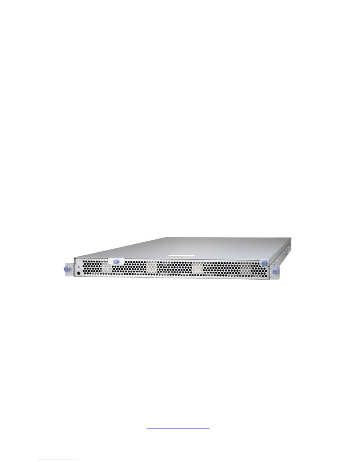
1.5 About the Product
The following views show you the product.
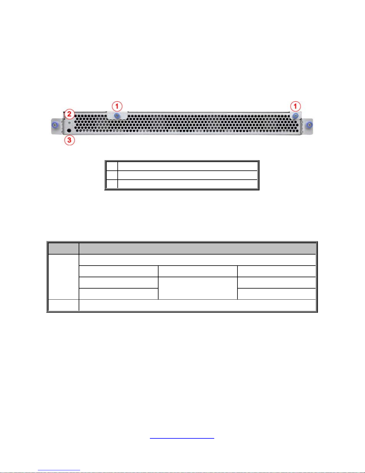
1.5.1 System Front View
1
Thumb screw (for top cover)
2
Power Button with LED
3
Reset Button
1.5.2 Front Panel Buttons
Button State Description
Power
Turn on and off the system (Use a pin).
State Color Behavior
Power On
Green
Solid On
Power Off Off
Reset Press to reset the system.
20
http://www.tyan.com
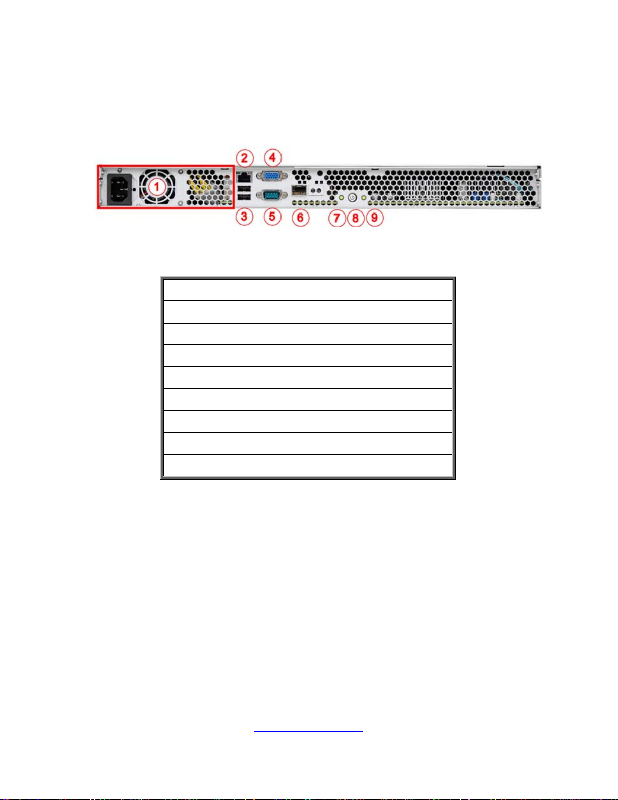
1.5.3 System Rear View
1
Power Supply
2
LAN1 (I210, shared BMC)
3
USB2.0 Ports
4
VGA Port
5
Serial Port (COM1)
6
10GB LAN Port
7
Reset Button
8 Power Button with LED
9 ID Button
http://www.tyan.com
21
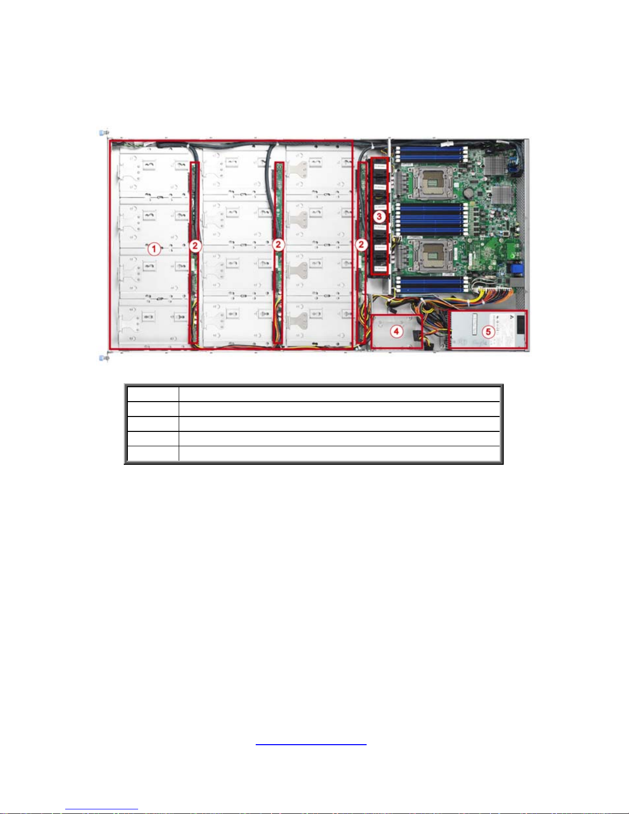
1.5.4 Internal View
1
(12) 3.5” SAS/SATA 6G HDD from LSI SAS2308
2
M7051G86-BP6-4 HDD Backplane Board
3
(6) System Fans
4
(1) 2.5” SATA 6G SSD from PCH
5
Power supply

http://www.tyan.com
22
NOTE

23
http://www.tyan.com
Chapter 2: Setting Up
2.0.1 Before you Begin
This chapter explains how to install the CPUs, CPU heatsinks,
memory modules, and hard drives. Instructions on inserting add on
cards are also given.
2.0.2 Work Area
Make sure you have a stable, clean working environment. Dust and
dirt can get into components and cause malfunctions. Use
containers to keep small components separated. Putting all small
components in separate containers prevents them from becoming
lost. Adequate lighting and proper tools can prevent you from
accidentally damaging the internal components.
2.0.3 Tools
The following procedures require only a few tools, including the
following:
A cross head (Phillips) scre wdriver
A grounding strap or an anti-static pad
Most of the electrical and mechanical connections can be
disconnected with your hands. It is recommended that you do not
use pliers to remove connectors as it may damage the soft metal or
plastic parts of the connectors.
24
http://www.tyan.com
2.0.4 Precautions
Components and electronic circuit boards can be damaged by
discharges of static electricity. Working on a system that is connected
to a power supply can be extremely dangerous. Follow the guidelines
below to avoid damage to GT86A-B7051 or injury to yourself.
Ground yourself properly before removing the top cover of the
system. Unplug the power from the power supply and then
touch a safely grounded object to release static charge (i.e.
power supply case). If available, wear a grounded wrist strap.
Alternatively, discharge any static electricity by touching the
bare metal chassis of the unit case, or the bare metal body of
any other grounded appliance.
Avoid touching motherboard components, IC chips, connectors,
memory modules, and leads.
The motherboard is pre-installed in the system. When
removing the motherboard, always place it on a grounded
anti-static surface until you are ready to reinstall it.
Hold electronic circuit boards by the edges only. Do not touch
the components on the board unless it is necessary to do so.
Do not flex or stress circuit boards.
Leave all components inside the static-proof packaging that
they ship with until they are ready for installation.
After replacing optional devices, make sure all screws, springs,
or other small parts are in place and are not left loos e inside
the case. Metallic parts or metal flakes can cause electrical
shorts.
CAUTION: Please note that the following illustrations ma y not
look exactly like the rackmount server you purchased.
Therefore, the illustrations should be held for your reference
only.
25
http://www.tyan.com
2.1 Installing Motherboard Components
This section describes how to install components on to the motherboard, including
CPUs, memory modules, HDD and PCI-E cards.
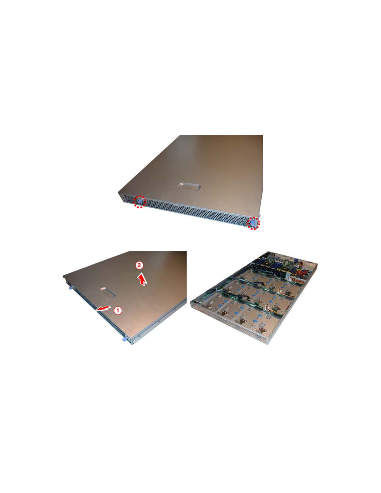
2.1.1 Removing the Chassis Cover
Follow these instructions to remove the GT86A-B7051 chassis cover.
1. Loosen the thumb screw on the front.
2. Slide the top cover forward and then lift it up.
26
http://www.tyan.com
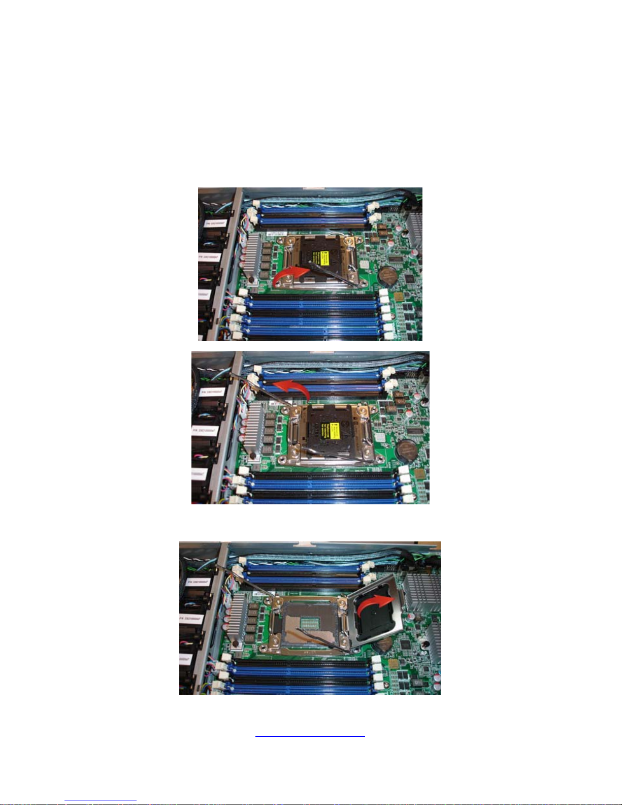
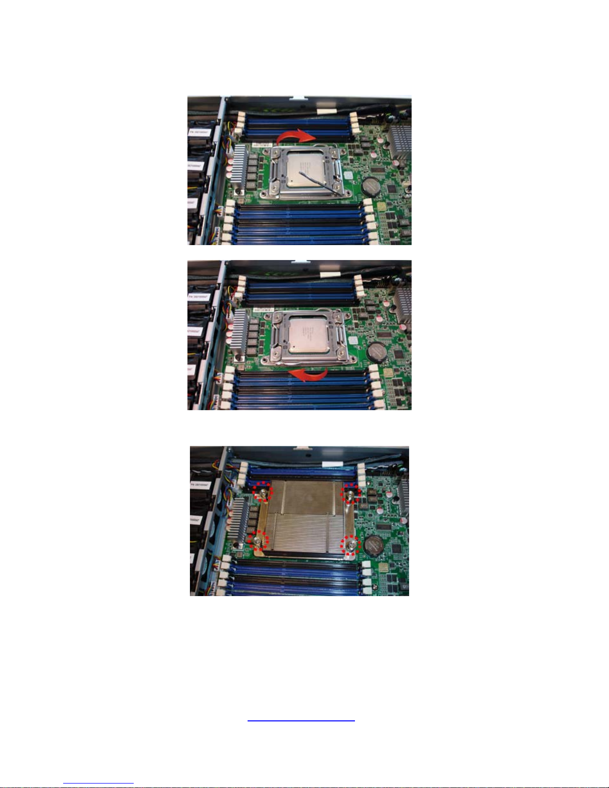
2.1.2 Installing the CPU and Heatsink
Follow the steps below to install CPUs and CPU heatsinks.
1. Locate the CPU sockets. Always start with CPU0 first.
2. Pull the levers slightly away from the socket and then push them to a fully
open position.
3. Lift the CPU socket cover to a fully open position.
http://www.tyan.com
27
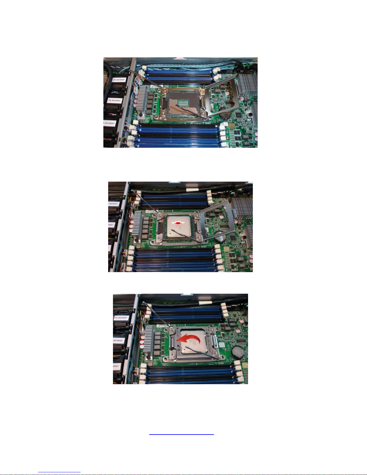
4. Remove the protection cap from the CPU socket.
5. Place the CPU into the socket making sure that the gold arrow is located
in the right direction.
6. Close the CPU socket cover.
http://www.tyan.com
28
7. Press the levers down to secure the CPU.
8. Position the heatsink on top of the CPU and secure it with 4 screws.
9. Repeat steps 2 to 8 to install the second CPU and heatsink.
http://www.tyan.com
29
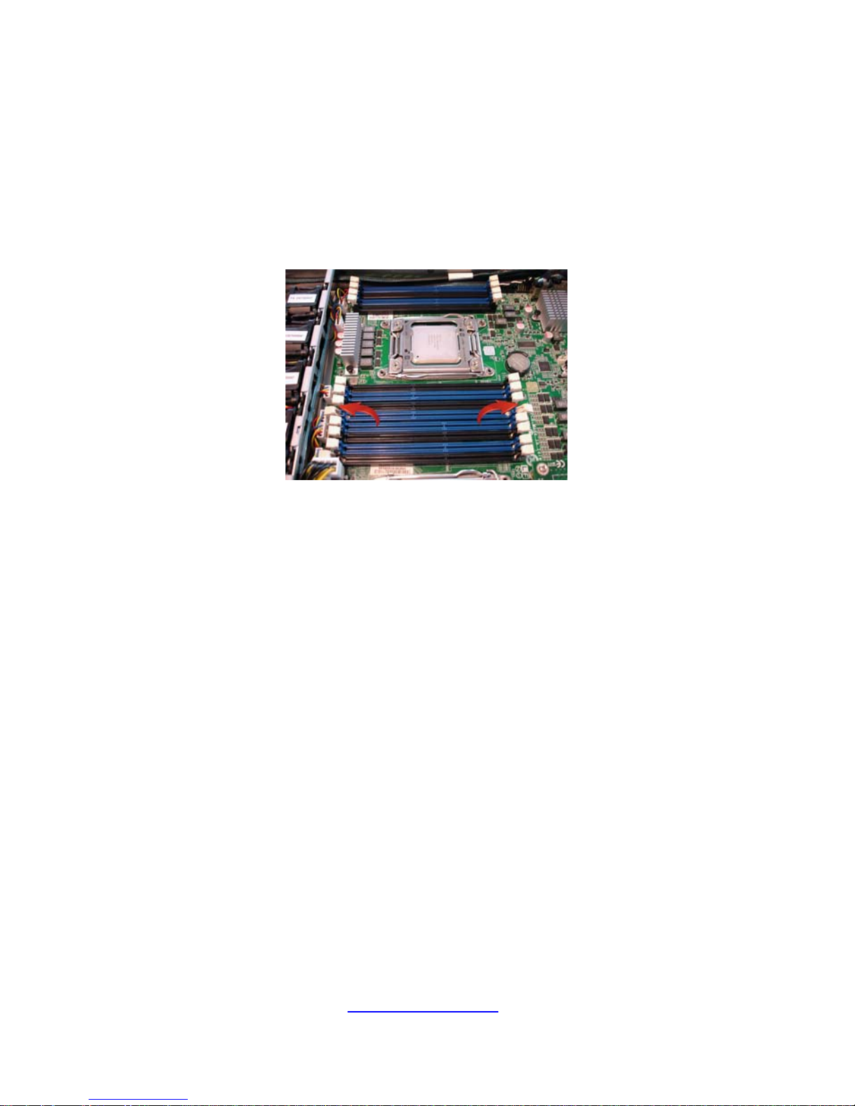
2.1.3 Installing the Memory
Follow these instructions to install the memory modules onto the motherboard.
1. Locate the memory slots on the motherboard.
2. Press the memory slot locking levers in the direction of the arrows as
shown in the following illustration.
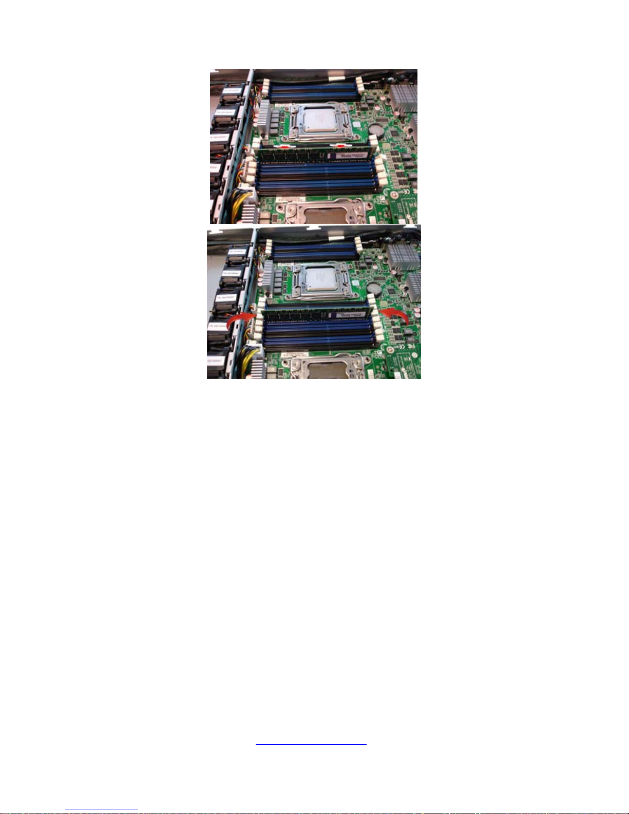
3. Align and insert the memory module down onto the slot. When inserted
properly, the memory slot locking levers lock automatically on the
indentations at the ends of the module. Follow the recommended
memory population table to install the other memory modules.
http://www.tyan.com
30
 Loading...