

Page 1
1
http://www.tyan.com
FT77CB7079
Service Engineer’s Manual
Page 2

2
http://www.tyan.com
Page 3

3
http://www.tyan.com
PREFACE
Copyright
This publication, including all photographs, illustrations, and software, is
protected under international copyright laws, with all rights reserved.
Neither this manual, nor any material contained herein, may be reproduced
without written consent of manufacturer.
Copyright 2014 MiTAC International Corporation. All rights reserved. TYAN® is a
registered trademark of MiTAC International Corporation.
Version 1.0e
Disclaimer
Information contained in this document is furnished by MiTAC Computer
Corporation and has been reviewed for accuracy and reliability prior to printing.
TYAN® assumes no liability whatsoever, and disclaims any express or implied
warranty, relating to sale and/or use of TYAN® products including liability or
warranties relating to fitness for a particular purpose or merchantability. TYAN®
retains the right to make changes to produce descriptions and/or specifications at
any time, without notice. In no event will TYAN® be held liable for any direct or
indirect, incidental or consequential damage, loss of use, loss of data or other
malady resulting from errors or inaccuracies of information contained in this
document.
Trademark Recognition
All registered and unregistered trademarks and company names contain- -ed in
this manual are property of their respective owners including, but not limited to the
following.
TYAN® is a trademark of MiTAC Computer Corporation.
Intel® is a trademark of Intel Corporation.
AMI®, AMIBIOS® and combinations thereof are trademarks of AMI Technologies.
Microsoft®, Windows® are trademarks of Microsoft Corporation.
Winbond® is a trademark of Winbond Electronics Corporation.
Portable Document Format (PDF) is a trademark of Adobe Corporation.
Page 4
4
http://www.tyan.com
FCC Declaration
Notice for the USA
Compliance Information Statement (Declaration of Conformity
Procedure) DoC FCC Part 15: This device complies with part 15 of the
FCC Rules
This device complies with Part 15 of the FCC Rules. Operation is subject
to the following conditions:
·This device must not cause harmful interference.
·This device must accept any interference received, including interference that may
cause undesirable operation.
This equipment has been tested and found to comply with the limits for a Class A
digital device, pursuant to Part 15 of the FCC Rules. These limits are designed to
provide reasonable protection against harmful interference when the equipment is
operated in a commercial environment. This equipment generates, uses, and can
radiate radio frequency energy and, if not installed and used in accordance with the
instruction manual, may cause harmful interference to radio communications.
Operation of this equipment in a residential area is likely to cause harmful
interference in which case the user will be required to correct the interference at his
own expense.
Notice for Canada
This Class A digital apparatus complies with Canadian ICES-003. Cet
appareil numérique de la Classe A est conforme à la norme NMB-003
du Canada.
Notice for Europe (CE Mark)
This product is in conformity with the Council
Directive 2004/108/EC.
CAUTION: Lithium battery included with this board. Do not puncture,
mutilate, or dispose of battery in fire. There will be danger of explosion if
battery is incorrectly replaced. Replace only with the same or equivalent
type recommended by manufacturer. Dispose of used battery according
to manufacturer instructions and in accordance with your local regulations.
Page 5

5
http://www.tyan.com
About this Manual
This Manual is intended for experienced users and integrators with
hardware knowledge of personal computers.
It is aimed to provide you with instructions on installing your TYAN
FT77C-B7079.
How this guide is organized
This guide contains the following parts:
Chapter 1: Overview
This chapter give an introduction to the FT77C-B7079 barebones, standard
parts list, and accessories. describes the external components, gives a table of
key
Chapter2: Setting Up
This chapter Covers procedures on installing the CPU, memory modules, add
on card and hard drives. Give an overview about the FT77C-B7079 barebone
from an overall angle.
Chapter 3: Replacing the Pre-installed Components
This chapter covers the removal and replacement procedures for pre-installed
components.
Chapter 4: Motherboard Information
This chapter lists the hardware setup procedures that you need to abide by when
installing system components. It includes description of the jumpers and connectors
on the motherboard.
Chapter5: BIOS Setup
This chapter tells how to change system settings through the BIOS setup menu.
Detailed descriptions of the BIOS parameters are also provided.
Chapter 6: Diagnostics
This chapter introduces some BIOS codes and technical terms to provide better
service for the customers.
Appendix:
This Chapter Describes the Fan and Temp sensors location; list the cable
connection and FRU part tables for reference of system setup and technical
support in case a problem arises with your system.
Page 6

6
http://www.tyan.com
SAFETY INFORMATION
Before installing and using FT77C-B7079, take note of the following precautions:
·Read all instructions carefully.
·Do not place the unit on an unstable surface, cart, or stand.
·Do not block the slots and opening on the unit, which are provided for
ventilation.
·Only use the power source indicated on the marking label. If you are not sure,
contact the power company.
·The unit uses a three-wire ground cable, which is equipped with a third pin to
ground the unit and prevent electric shock. Do not defeat the pur-
-pose of this pin. If you outlet does not support this kind of plug, contact
your electrician to replace your obsolete outlet.
·Do not place anything on the power cord. Place the power cord where it will not
be in the way of foot traffic.
·Follow all warnings and cautions in this manual and on the unit case.
·Do not push objects in the ventilation slots as they may touch high volta-
-ge components and result in shock and damage to the components.
·When replacing parts, ensure that you use parts specified by the manuf-
-acturer.
·When service or repairs have been done, perform routine safety checks
to verify that the system is operating correctly.
·Avoid using the system near water, in direct sunlight, or near a heating device.
·Cover the unit when not in use.
Page 7

7
http://www.tyan.com
Table of Contents
Chapter 1: Overview ....................................................................... 9
1.1 About the TYAN FT77C-B7079 ............................................. 9
1.2 Product Models ...................................................................... 9
1.4 Standard Parts List .............................................................. 22
1.4.1 Box Contents ................................................................ 22
1.4.2 Accessories .................................................................. 22
1.5 About the Product ................................................................ 23
1.5.1 System Front View ....................................................... 23
1.5.2 System Rear View ........................................................ 25
1.5.3 LED Definitions ............................................................. 26
1.5.4 Internal View ................................................................. 28
Chapter 2: Setting Up ................................................................... 29
2.0.1 Before you Begin .......................................................... 29
2.0.2 Work Area ..................................................................... 29
2.0.3 Tools ............................................................................. 29
2.0.4 Precautions ................................................................... 30
2.1 Installing Motherboard Components ................................... 31
2.1.1 Removing the Chassis Cover ....................................... 31
2.1.2 Installing the CPU and Heat sink .................................. 33
2.1.3 Installing the Memory ................................................... 36
2.1.4 Installing Expansion Cards ........................................... 37
2.1.5 Installing the Mezzanine Card ...................................... 39
2.1.6 Installing Hard Drives ................................................... 40
2.2 Rack Mounting ..................................................................... 43
2.2.1 Installing the Server in a Rack ...................................... 43
2.2.2 Installing the inner Rails to the Chassis ....................... 44
2.2.3 Installing the Outer Rails to the Rack ........................... 45
2.2.4 Rack mounting the Server ............................................ 46
Chapter 3: Replacing Pre-Installed Components ...................... 48
3.1 Introduction .......................................................................... 48
3.2 Disassembly Flowchart ........................................................ 48
3.3 Removing the Cover ............................................................ 49
3.4 Replacing the Power Supply ............................................... 49
3.5 Replacing HDD backplane .................................................. 50
3.5.1. HDD Back Plane Board Features ................................ 52
3.6 Replacing Power Distribution Board .................................... 54
3.7 Replace the power backplane Board .................................. 57
3.7.2 Pin Definition ................................................................ 60
3.8 Replacing the Riser Card .................................................... 62
Page 8

8
http://www.tyan.com
3.8.1 Riser card Feature ........................................................ 64
3.9 Replacing the System Fan Board ........................................ 65
3.9.1 M1801F77-Fan Board Features ................................... 67
3.9.2 Pin Definition ................................................................ 68
3.10 Replacing the Front Panel Board ...................................... 69
3.10.1 Front Pane Board Features ........................................ 70
3.10.2 Pin Definition ............................................................. 71
3.11 Replacing the Motherboard ............................................... 72
Chapter 4: Motherboard Information .......................................... 74
4.1 Board Image ........................................................................ 75
4.2 Block Diagram ..................................................................... 76
4.3 Mainboard Mechanical Drawing .......................................... 77
4.4 Board Parts, Jumpers and Connectors ............................... 78
4.5 Installing the Memory .......................................................... 89
4.6 Installing Add-In Cards ........................................................ 93
4.7 Installing the Power Supply ................................................. 94
Chapter 5: BIOS Setup .................................................................. 95
5.1 About the BIOS .................................................................... 95
5.2 Main Menu ........................................................................... 97
5.3 Advanced Menu ................................................................... 98
5.4 Intel RCSetup Menu .......................................................... 125
5.5 Server Management .......................................................... 150
5.6 Security .............................................................................. 153
5.7 Boot ................................................................................... 155
5.8 Save & Exit ........................................................................ 157
Chapter 6: Diagnostics ............................................................... 159
6.1 Flash Utility ........................................................................ 159
6.2 AMIBIOS Post Code (Aptio) .............................................. 160
Appendix I: Fan and Temp Sensors .......................................... 170
Appendix II: Cable Connection Tables ..................................... 175
Appendix III: FRU Parts Table .................................................... 177
Appendix IV:Glossary ................................................................. 179
Appendix V: Technical Support ................................................. 185
Page 9
9
http://www.tyan.com
Chapter 1: Overview
1.1 About the TYAN FT77C-B7079
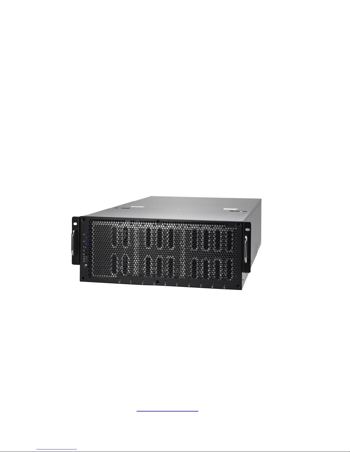
Congratulations on your purchase of the TYAN® FT77C-B7079, a highly
optimized rack-mountable 4U barebone system. FT77C-B7079 is designed to
support dual Intel® Xeon E5-2600V3 Series processors and up to 768GB
RDIMM/, 1,536GB LRDIMM/ and 3,072GB LRDIMM(3DS* DDR4 Memory),
providing a rich feature set and incredible performance. Leveraging advanced
technology from Intel®, FT77C-B7079 server system is capable of offering
scalable 32 and 64-bit computing, high-bandwidth memory design, and
lightning-fast PCI-E bus implementation. FT77C-B7079 not only enpowers your
company in today‟s demanding IT environment but also offers a smooth path for
future application usage.
TYAN® also offers the FT77C-B7079 in a version that can support up to ten 3.5”
or 2.5” hot-swap SATAIII HDDs.FT77C-B7079 uses rack-mountable 4U chassis
featuring a robust structure and a solid mechanical enclosure. All of this provides
FT77C-B7079 the power and flexibility to meet the needs of nearly any server
application.
1.2 Product Models
FT77C-B7079 divided to these SKUs bellow which contain different features
and chipsets:
B7079F77CV10HR-2T: support10G LAN
B7079F77CV10HR: standard platform
B7079F77CV10HR-2T-N: NVIDIA
®
Tesla GPU platform w/10G LAN
B7079F77CV10HR-2T-X: Intel
®
Xeon Phi™ GPU platform w/10G LAN
B7079F77CV10HR-N: NVIDIA
®
Tesla GPU platform
B7079F77CV10HR-X: Intel
®
Xeon Phi™ GPU platform
Page 10

10
http://www.tyan.com
1.3 Features
TYAN FT77CB7079 (B7079F77CV10HR-2T)
System
Form Factor
4U Rackmount
Gross Weight
35 kg
Chassis Model
FT77C
Dimension (D x W x H)
30.31" x 17.24" x 6.93" (770 x 438 x 176mm)
Motherboard
S7079GM2NR-2T
Front Panel
Buttons
(1) RST / (1) ID / (1) PWR w/ LED
LEDs
(1) HDD / (2) LAN / (1) ID / (1) IPMI/Warning
I/O Ports
(2) USB ports
External Drive
Bay
Type / Q'ty
3.5"/2.5" Hot-Swap / (10)
HDD backplane
support
SAS / SATA 6.0Gb/s
System Cooling
Configuration
FAN
(5+1) hot-swap 12cm fans
Power Supply
Efficiency
80 plus Platinum
Redundancy
2+1
Serviceability
Hot-swap
Input Range
100-127V AC / 200-240V AC
Output Watts
3,200 Watts
Processor
Supported CPU Series
Intel Xeon Processor E5-2600 v3 series
Socket Type / Q'ty
LGA2011 / (2)
Thermal Design
Power (TDP) wattage
Max up to 160W
System Bus
Up to 9.6/ 8.0/ 6.4 GT/s with Intel QuickPath
Interconnect (QPI) support
Chipset
Switch IC
(4)PLX PEX8747
PCH
Intel C612
Memory
Supported DIMM Qty
(12)+(12) DIMM slots
DIMM Type / Speed
RDIMM DDR4 2133/1866/1600 / LRDIMM DDR4
2133/1600 / LRDIMM 3DS DDR4 2133/1600
Capacity
Up to 768GB RDIMM/ 1,536GB LRDIMM/
3,072GB LRDIMM 3DS *Intel DDR4 Memory
POR
Memory channel
4 Channels per CPU
Memory voltage
1.2V
Expansion Slots
PCI-E
(8) PCI-E Gen3 x16 slots / (2) PCI-E Gen3 x8
slots(one for mezzanine card)
Pre-install TYAN Riser
Card
M2210-L8-1F, PCI-E Gen3 x8 slot (left)
LAN Port Q'ty
(2) 10GbE ports (1 port shared with IPMI)
Page 11
11
http://www.tyan.com
Controller
Intel X540-AT2
Storage SATA
Connector
(2) Mini-SAS (8-ports) + (2) SATA (totally support
10 ports)
Controller
Intel C612
Speed
6.0 Gb/s
RAID
RAID 0/1/10/5 (Intel RST)
Graphic
Connector type
D-Sub 15-pin
Chipset
Aspeed AST2400
I/O Ports
USB
(4) ports (2 at front, 4 at rear)
VGA
(1) D-Sub 15-pin port
RJ-45
(2) ports
System
Monitoring
Chipset
Aspeed AST2400
Voltage
Monitors voltage for CPU, memory, chipset &
power supply
Temperature
Monitors temperature for CPU & memory
LED
Over temperature warning indicator / Fan & PSU
fail LED indicator
Others
Watchdog timer support
Server
Management
Onboard Chipset
Onboard Aspeed AST2400
AST2400 IPMI Feature
IPMI 2.0 compliant baseboard management
controller (BMC) / Supports storage over IP and
remote platform-flash / USB 2.0 virtual hub
AST2400 iKVM
Feature
24-bit high quality video compression / 10/100
Mb/s MAC interface
BIOS
Brand / ROM size
16MB
Feature
SMBIOS 2.7/PnP/Wake on LAN / ACPI 3.0/PXE
boot
Operating System OS supported list
Please refer to our Intel OS supported list.
Regulation
FCC (DoC)
Class A
CE (DoC)
Yes
Operating
Environment
Operating Temp.
10° C ~ 35° C (50° F~ 95° F)
Non-operating Temp.
- 40° C ~ 70° C (-40° F ~ 158° F)
In/Non-operating
Humidity
90%, non-condensing at 35° C
RoHS RoHS 6/6 Compliant
Yes
Package Contains
Barebone
(1) FT77C-B7079 Barebone
Manual
(1) Quick Installation Guide
Installation CD
(1) TYAN installation CD
Cable Others
(8) GPU power cables
TYAN FT77CB7079 (B7079F77CV10HR)
System Form Factor
4U Rackmount
Page 12

12
http://www.tyan.com
Gross Weight
35 kg
Chassis Model
FT77C
Dimension (D x W x H)
30.31" x 17.24" x 6.93" (770 x 438 x 176mm)
Motherboard
S7079GM2NR
Front Panel
Buttons
(1) RST / (1) ID / (1) PWR w/ LED
LEDs
(1) HDD / (2) LAN / (1) ID / (1) IPMI/Warning
I/O Ports
(2) USB ports
External Drive
Bay
Type / Q'ty
3.5"/2.5" Hot-Swap / (10)
HDD backplane
support
SAS / SATA 6.0Gb/s
System Cooling
Configuration
FAN
(5+1) hot-swap 12cm fans
Power Supply
Efficiency
80 plus Platinum
Redundancy
2+1
Serviceability
Hot-swap
Input Range
100-127V AC / 200-240V AC
Output Watts
3,200 Watts
Processor
Supported CPU Series
Intel Xeon Processor E5-2600 v3 series
Socket Type / Q'ty
LGA2011 / (2)
Thermal Design
Power (TDP) wattage
Max up to 160W
System Bus
Up to 9.6/ 8.0/ 6.4 GT/s with Intel QuickPath
Interconnect (QPI) support
Chipset
Switch IC
(4)PLX PEX8747
PCH
Intel C612
Memory
Supported DIMM Qty
(12)+(12) DIMM slots
DIMM Type / Speed
RDIMM DDR4 2133/1866/1600 / LRDIMM DDR4
2133/1600 / LRDIMM 3DS DDR4 2133/1600
Capacity
Up to 768GB RDIMM/ 1,536GB LRDIMM/
3,072GB LRDIMM 3DS *Intel DDR4 Memory
POR
Memory channel
4 Channels per CPU
Memory voltage
1.2V
Expansion Slots
PCI-E
(8) PCI-E Gen3 x16 slots / (2) PCI-E Gen3 x8
slots(one for mezzanine card)
Pre-install TYAN Riser
Card
M2210-L8-1F, PCI-E Gen3 x8 slot (left)
LAN
Port Q'ty
(2) GbE ports (1 port shared with IPMI)
Controller
Intel I350-BT2
Storage SATA
Connector
(2) Mini-SAS (8-ports) + (2) SATA (totally support
10 ports)
Controller
Intel C612
Speed
6.0 Gb/s
Page 13

13
http://www.tyan.com
RAID
RAID 0/1/10/5 (Intel RST)
Graphic
Connector type
D-Sub 15-pin
Chipset
Aspeed AST2400
I/O Ports
USB
(4) ports (2 at front, 4 at rear)
VGA
(1) D-Sub 15-pin port
RJ-45
(2) ports
System
Monitoring
Chipset
Aspeed AST2400
Voltage
Monitors voltage for CPU, memory, chipset &
power supply
Temperature
Monitors temperature for CPU & memory
LED
Over temperature warning indicator / Fan & PSU
fail LED indicator
Others
Watchdog timer support
Server
Management
Onboard Chipset
Onboard Aspeed AST2400
AST2400 IPMI Feature
IPMI 2.0 compliant baseboard management
controller (BMC) / Supports storage over IP and
remote platform-flash / USB 2.0 virtual hub
AST2400 iKVM
Feature
24-bit high quality video compression / 10/100
Mb/s MAC interface
BIOS
Brand / ROM size
16MB
Feature
SMBIOS 2.7/PnP/Wake on LAN / ACPI 3.0/PXE
boot
Operating System OS supported list
Please refer to our Intel OS supported list.
Regulation
FCC (DoC)
Class A
CE (DoC)
Yes
Operating
Environment
Operating Temp.
10° C ~ 35° C (50° F~ 95° F)
Non-operating Temp.
- 40° C ~ 70° C (-40° F ~ 158° F)
In/Non-operating
Humidity
90%, non-condensing at 35° C
RoHS RoHS 6/6 Compliant
Yes
Package Contains
Barebone
(1) FT77C-B7079 Barebone
Manual
(1) Quick Installation Guide
Installation CD
(1) TYAN installation CD
Cable Others
(8) GPU power cables
TYAN FT77CB7079 (B7079F77CV10HR-2T-N)
System
Form Factor
4U Rackmount
Gross Weight
35 kg
Chassis Model
FT77C
Dimension (D x W x H)
30.31" x 17.24" x 6.93" (770 x 438 x 176mm)
Page 14

14
http://www.tyan.com
Motherboard
S7079GM2NR-2T
Front Panel
Buttons
(1) RST / (1) ID / (1) PWR w/ LED
LEDs
(1) HDD / (2) LAN / (1) ID / (1) IPMI/Warning
I/O Ports
(2) USB ports
External Drive
Bay
Type / Q'ty
3.5"/2.5" Hot-Swap / (10)
HDD backplane
support
SAS / SATA 6.0Gb/s
System Cooling
Configuration
FAN
(5+1) hot-swap 12cm fans
Power Supply
Efficiency
80 plus Platinum
Redundancy
2+1
Serviceability
Hot-swap
Input Range
100-127V AC / 200-240V AC
Output Watts
3,200 Watts
Processor
Supported CPU Series
Intel Xeon Processor E5-2600 v3 series
Socket Type / Q'ty
LGA2011 / (2)
Thermal Design
Power (TDP) wattage
Max up to 160W
System Bus
Up to 9.6/ 8.0/ 6.4 GT/s with Intel QuickPath
Interconnect (QPI) support
Chipset
Switch IC
(4)PLX PEX8747
PCH
Intel C612
Memory
Supported DIMM Qty
(12)+(12) DIMM slots
DIMM Type / Speed
RDIMM DDR4 2133/1866/1600 / LRDIMM DDR4
2133/1600 / LRDIMM 3DS DDR4 2133/1600
Capacity
Up to 768GB RDIMM/ 1,536GB LRDIMM/
3,072GB LRDIMM 3DS *Intel DDR4 Memory
POR
Memory channel
4 Channels per CPU
Memory voltage
1.2V
Expansion Slots
PCI-E
(8) PCI-E Gen3 x16 slots / (2) PCI-E Gen3 x8
slots(one for mezzanine card)
Pre-install TYAN Riser
Card
M2210-L8-1F, PCI-E Gen3 x8 slot (left)
LAN
Port Q'ty
(2) 10GbE ports (1 port shared with IPMI)
Controller
Intel X540-AT2
Storage SATA
Connector
(2) Mini-SAS (8-ports) + (2) SATA (totally support
10 ports)
Controller
Intel C612
Speed
6.0 Gb/s
RAID
RAID 0/1/10/5 (Intel RST)
Graphic
Connector type
D-Sub 15-pin
Chipset
Aspeed AST2400
Page 15
15
http://www.tyan.com
I/O Ports
USB
(4) ports (2 at front, 4 at rear)
VGA
(1) D-Sub 15-pin port
RJ-45
(2) ports
System
Monitoring
Chipset
Aspeed AST2400
Voltage
Monitors voltage for CPU, memory, chipset &
power supply
Temperature
Monitors temperature for CPU & memory
LED
Over temperature warning indicator / Fan & PSU
fail LED indicator
Others
Watchdog timer support
Server
Management
Onboard Chipset
Onboard Aspeed AST2400
AST2400 IPMI Feature
IPMI 2.0 compliant baseboard management
controller (BMC) / Supports storage over IP and
remote platform-flash / USB 2.0 virtual hub
AST2400 iKVM
Feature
24-bit high quality video compression / 10/100
Mb/s MAC interface
BIOS
Brand / ROM size
16MB
Feature
SMBIOS 2.7/PnP/Wake on LAN / ACPI 3.0/PXE
boot
Operating System OS supported list
Please refer to our Intel OS supported list.
Regulation
FCC (DoC)
Class A
CE (DoC)
Yes
Operating
Environment
Operating Temp.
10° C ~ 35° C (50° F~ 95° F)
Non-operating Temp.
- 40° C ~ 70° C (-40° F ~ 158° F)
In/Non-operating
Humidity
90%, non-condensing at 35° C
RoHS RoHS 6/6 Compliant
Yes
Package Contains
Barebone
(1) FT77C-B7079 w/NV Tesla-aware FW
Barebone
Manual
(1) Quick Installation Guide
Installation CD
(1) TYAN installation CD
Others
(1) CPU air duct / (8) For NV-Tesla GPU card
brackets
Cable Others
(8) GPU power cables
TYAN FT77CB7079 (B7079F77CV10HR-2T-X)
System
Form Factor
4U Rackmount
Gross Weight
35 kg
Chassis Model
FT77C
Dimension (D x W x H)
30.31" x 17.24" x 6.93" (770 x 438 x 176mm)
Motherboard
S7079GM2NR-2T
Front Panel Buttons
(1) RST / (1) ID / (1) PWR w/ LED
Page 16

16
http://www.tyan.com
LEDs
(1) HDD / (2) LAN / (1) ID / (1) IPMI/Warning
I/O Ports
(2) USB ports
External Drive
Bay
Type / Q'ty
3.5"/2.5" Hot-Swap / (10)
HDD backplane
support
SAS / SATA 6.0Gb/s
System Cooling
Configuration
FAN
(5+1) hot-swap 12cm fans
Power Supply
Efficiency
80 plus Platinum
Redundancy
2+1
Serviceability
Hot-swap
Input Range
100-127V AC / 200-240V AC
Output Watts
3,200 Watts
Processor
Supported CPU Series
Intel Xeon Processor E5-2600 v3 series
Socket Type / Q'ty
LGA2011 / (2)
Thermal Design
Power (TDP) wattage
Max up to 160W
System Bus
Up to 9.6/ 8.0/ 6.4 GT/s with Intel QuickPath
Interconnect (QPI) support
Chipset
Switch IC
(4)PLX PEX8747
PCH
Intel C612
Memory
Supported DIMM Qty
(12)+(12) DIMM slots
DIMM Type / Speed
RDIMM DDR4 2133/1866/1600 / LRDIMM DDR4
2133/1600 / LRDIMM 3DS DDR4 2133/1600
Capacity
Up to 768GB RDIMM/ 1,536GB LRDIMM/
3,072GB LRDIMM 3DS *Intel DDR4 Memory
POR
Memory channel
4 Channels per CPU
Memory voltage
1.2V
Expansion Slots
PCI-E
(8) PCI-E Gen3 x16 slots / (2) PCI-E Gen3 x8
slots(one for mezzanine card)
Pre-install TYAN Riser
Card
M2210-L8-1F, PCI-E Gen3 x8 slot (left)
LAN
Port Q'ty
(2) 10GbE ports (1 port shared with IPMI)
Controller
Intel X540-AT2
Storage SATA
Connector
(2) Mini-SAS (8-ports) + (2) SATA (totally support
10 ports)
Controller
Intel C612
Speed
6.0 Gb/s
RAID
RAID 0/1/10/5 (Intel RST)
Graphic
Connector type
D-Sub 15-pin
Chipset
Aspeed AST2400
I/O Ports
USB
(4) ports (2 at front, 4 at rear)
VGA
(1) D-Sub 15-pin port
Page 17
17
http://www.tyan.com
RJ-45
(2) ports
System
Monitoring
Chipset
Aspeed AST2400
Voltage
Monitors voltage for CPU, memory, chipset &
power supply
Temperature
Monitors temperature for CPU & memory
LED
Over temperature warning indicator / Fan & PSU
fail LED indicator
Others
Watchdog timer support
Server
Management
Onboard Chipset
Onboard Aspeed AST2400
AST2400 IPMI Feature
IPMI 2.0 compliant baseboard management
controller (BMC) / Supports storage over IP and
remote platform-flash / USB 2.0 virtual hub
AST2400 iKVM
Feature
24-bit high quality video compression / 10/100
Mb/s MAC interface
BIOS
Brand / ROM size
16MB
Feature
SMBIOS 2.7/PnP/Wake on LAN / ACPI 3.0/PXE
boot
Operating System OS supported list
Please refer to our Intel OS supported list.
Regulation
FCC (DoC)
Class A
CE (DoC)
Yes
Operating
Environment
Operating Temp.
10° C ~ 35° C (50° F~ 95° F)
Non-operating Temp.
- 40° C ~ 70° C (-40° F ~ 158° F)
In/Non-operating
Humidity
90%, non-condensing at 35° C
RoHS RoHS 6/6 Compliant
Yes
Package Contains
Barebone
(1) FT77C-B7079 w/Intel Xeon Phi-aware FW
Barebone
Manual
(1) Quick Installation Guide
Installation CD
(1) TYAN installation CD
Others
(1) CPU air duct / (8) For Intel Xeon Phi card
brackets
Cable Others
(8) GPU power cables
TYAN FT77CB7079 (B7079F77CV10HR-N)
System
Form Factor
4U Rackmount
Gross Weight
35 kg
Chassis Model
FT77C
Dimension (D x W x H)
30.31" x 17.24" x 6.93" (770 x 438 x 176mm)
Motherboard
S7079GM2NR
Front Panel
Buttons
(1) RST / (1) ID / (1) PWR w/ LED
LEDs
(1) HDD / (2) LAN / (1) ID / (1) IPMI/Warning
I/O Ports
(2) USB ports
Page 18

18
http://www.tyan.com
External Drive
Bay
Type / Q'ty
3.5"/2.5" Hot-Swap / (10)
HDD backplane
support
SAS / SATA 6.0Gb/s
System Cooling
Configuration
FAN
(5+1) hot-swap 12cm fans
Power Supply
Efficiency
80 plus Platinum
Redundancy
2+1
Serviceability
Hot-swap
Input Range
100-127V AC / 200-240V AC
Output Watts
3,200 Watts
Processor
Supported CPU Series
Intel Xeon Processor E5-2600 v3 series
Socket Type / Q'ty
LGA2011 / (2)
Thermal Design
Power (TDP) wattage
Max up to 160W
System Bus
Up to 9.6/ 8.0/ 6.4 GT/s with Intel QuickPath
Interconnect (QPI) support
Chipset
Switch IC
(4)PLX PEX8747
PCH
Intel C612
Memory
Supported DIMM Qty
(12)+(12) DIMM slots
DIMM Type / Speed
RDIMM DDR4 2133/1866/1600 / LRDIMM DDR4
2133/1600 / LRDIMM 3DS DDR4 2133/1600
Capacity
Up to 768GB RDIMM/ 1,536GB LRDIMM/
3,072GB LRDIMM 3DS *Intel DDR4 Memory
POR
Memory channel
4 Channels per CPU
Memory voltage
1.2V
Expansion Slots
PCI-E
(8) PCI-E Gen3 x16 slots / (2) PCI-E Gen3 x8
slots(one for mezzanine card)
Pre-install TYAN Riser
Card
M2210-L8-1F, PCI-E Gen3 x8 slot (left)
LAN
Port Q'ty
(2) GbE ports (1 port shared with IPMI)
Controller
Intel I350-BT2
Storage SATA
Connector
(2) Mini-SAS (8-ports) + (2) SATA (totally support
10 ports)
Controller
Intel C612
Speed
6.0 Gb/s
RAID
RAID 0/1/10/5 (Intel RST)
Graphic
Connector type
D-Sub 15-pin
Chipset
Aspeed AST2400
I/O Ports
USB
(4) ports (2 at front, 4 at rear)
VGA
(1) D-Sub 15-pin port
RJ-45
(2) ports
System Chipset
Aspeed AST2400
Page 19
19
http://www.tyan.com
Monitoring
Voltage
Monitors voltage for CPU, memory, chipset &
power supply
Temperature
Monitors temperature for CPU & memory
LED
Over temperature warning indicator / Fan & PSU
fail LED indicator
Others
Watchdog timer support
Server
Management
Onboard Chipset
Onboard Aspeed AST2400
AST2400 IPMI Feature
IPMI 2.0 compliant baseboard management
controller (BMC) / Supports storage over IP and
remote platform-flash / USB 2.0 virtual hub
AST2400 iKVM
Feature
24-bit high quality video compression / 10/100
Mb/s MAC interface
BIOS
Brand / ROM size
16MB
Feature
SMBIOS 2.7/PnP/Wake on LAN / ACPI 3.0/PXE
boot
Operating System OS supported list
Please refer to our Intel OS supported list.
Regulation
FCC (DoC)
Class A
CE (DoC)
Yes
Operating
Environment
Operating Temp.
10° C ~ 35° C (50° F~ 95° F)
Non-operating Temp.
- 40° C ~ 70° C (-40° F ~ 158° F)
In/Non-operating
Humidity
90%, non-condensing at 35° C
RoHS RoHS 6/6 Compliant
Yes
Package Contains
Barebone
(1) FT77C-B7079 w/NV Tesla-aware FW
Barebone
Manual
(1) Quick Installation Guide
Installation CD
(1) TYAN installation CD
Others
(1) CPU air duct / (8) For NV-Tesla GPU card
brackets
Cable Others
(8) GPU power cables
TYAN FT77CB7079 (B7079F77CV10HR-X)
System
Form Factor
4U Rackmount
Gross Weight
35 kg
Chassis Model
FT77C
Dimension (D x W x H)
30.31" x 17.24" x 6.93" (770 x 438 x 176mm)
Motherboard
S7079GM2NR
Front Panel
Buttons
(1) RST / (1) ID / (1) PWR w/ LED
LEDs
(1) HDD / (2) LAN / (1) ID / (1) IPMI/Warning
I/O Ports
(2) USB ports
External Drive
Bay
Type / Q'ty
3.5"/2.5" Hot-Swap / (10)
HDD backplane
SAS / SATA 6.0Gb/s
Page 20

20
http://www.tyan.com
support
System Cooling
Configuration
FAN
(5+1) hot-swap 12cm fans
Power Supply
Efficiency
80 plus Platinum
Redundancy
2+1
Serviceability
Hot-swap
Input Range
100-127V AC / 200-240V AC
Output Watts
3,200 Watts
Processor
Supported CPU Series
Intel Xeon Processor E5-2600 v3 series
Socket Type / Q'ty
LGA2011 / (2)
Thermal Design
Power (TDP) wattage
Max up to 160W
System Bus
Up to 9.6/ 8.0/ 6.4 GT/s with Intel QuickPath
Interconnect (QPI) support
Chipset
Switch IC
(4)PLX PEX8747
PCH
Intel C612
Memory
Supported DIMM Qty
(12)+(12) DIMM slots
DIMM Type / Speed
RDIMM DDR4 2133/1866/1600 / LRDIMM DDR4
2133/1600 / LRDIMM 3DS DDR4 2133/1600
Capacity
Up to 768GB RDIMM/ 1,536GB LRDIMM/
3,072GB LRDIMM 3DS *Intel DDR4 Memory
POR
Memory channel
4 Channels per CPU
Memory voltage
1.2V
Expansion Slots
PCI-E
(8) PCI-E Gen3 x16 slots / (2) PCI-E Gen3 x8
slots(one for mezzanine card)
Pre-install TYAN Riser
Card
M2210-L8-1F, PCI-E Gen3 x8 slot (left)
LAN
Port Q'ty
(2) GbE ports (1 port shared with IPMI)
Controller
Intel I350-BT2
Storage SATA
Connector
(2) Mini-SAS (8-ports) + (2) SATA (totally support
10 ports)
Controller
Intel C612
Speed
6.0 Gb/s
RAID
RAID 0/1/10/5 (Intel RST)
Graphic
Connector type
D-Sub 15-pin
Chipset
Aspeed AST2400
I/O Ports
USB
(4) ports (2 at front, 4 at rear)
VGA
(1) D-Sub 15-pin port
RJ-45
(2) ports
System
Monitoring
Chipset
Aspeed AST2400
Voltage
Monitors voltage for CPU, memory, chipset &
power supply
Page 21
21
http://www.tyan.com
Temperature
Monitors temperature for CPU & memory
LED
Over temperature warning indicator / Fan & PSU
fail LED indicator
Others
Watchdog timer support
Server
Management
Onboard Chipset
Onboard Aspeed AST2400
AST2400 IPMI Feature
IPMI 2.0 compliant baseboard management
controller (BMC) / Supports storage over IP and
remote platform-flash / USB 2.0 virtual hub
AST2400 iKVM
Feature
24-bit high quality video compression / 10/100
Mb/s MAC interface
BIOS
Brand / ROM size
16MB
Feature
SMBIOS 2.7/PnP/Wake on LAN / ACPI 3.0/PXE
boot
Operating System OS supported list
Please refer to our Intel OS supported list.
Regulation
FCC (DoC)
Class A
CE (DoC)
Yes
Operating
Environment
Operating Temp.
10° C ~ 35° C (50° F~ 95° F)
Non-operating Temp.
- 40° C ~ 70° C (-40° F ~ 158° F)
In/Non-operating
Humidity
90%, non-condensing at 35° C
RoHS RoHS 6/6 Compliant
Yes
Package Contains
Barebone
(1) FT77C-B7079 w/Intel Xeon Phi-aware FW
Barebone
Manual
(1) Quick Installation Guide
Installation CD
(1) TYAN installation CD
Others
(1) CPU air duct / (8) For Intel Xeon Phi card
brackets
Cable Others
(8) GPU power cables
Page 22

22
http://www.tyan.com
1.4 Standard Parts List
This section describes FT77C-B7079 package contents and accessories.
Open the box carefully and ensure that all components are present and
undamaged. The product should arrive packaged as illustrated below.
1.4.1 Box Contents
FT77C-B7079 Chassis Kit
(1) 4U chassis
(2+1) 3,200W (80+ Platinum) w/ PFC redundant power supply
(5+1) 120*120*38 system fans (pre-installed)
(1) S7079 Mother Board(pre-installed)
(1) M1713F77C-FPB front panel board (pre-installed)
(1) M1809F77A-FB fan board (pre-installed)
(1) M2210-L8-1F riser card (pre-installed)
(1) M7059F77-D-PBP Power Backplane (pre-installed)
(1) M7059F77-D-PDB Power Distribution Board (pre-installed)
(1) M1262F77C-BP6-10 HDD Backplane (pre-installed)
1.4.2 Accessories
If any items are missing or appear damaged, contract your retailer or browse to
TYAN®‟s website for service: http://www.tyan.com.
FT77C-B7079 Accessory Kit
(1) Rail kit
(2) Rail screw kit
(2) CPU heatsink
(3) US power cord
(3) EU power cord
(1) Mounting ears
(16) 2*3P GPU power cable
(8) 2*4P GPU power cable
(1) Display port cable
(1) Screw Standoff
(1) TYAN Driver CD
(8) GPU Card Holder bracket with screw (optional)
(8) GPU Card Holder bracket with screw (optional)
Page 23
23
http://www.tyan.com
1.5 About the Product
The following views show you the product.
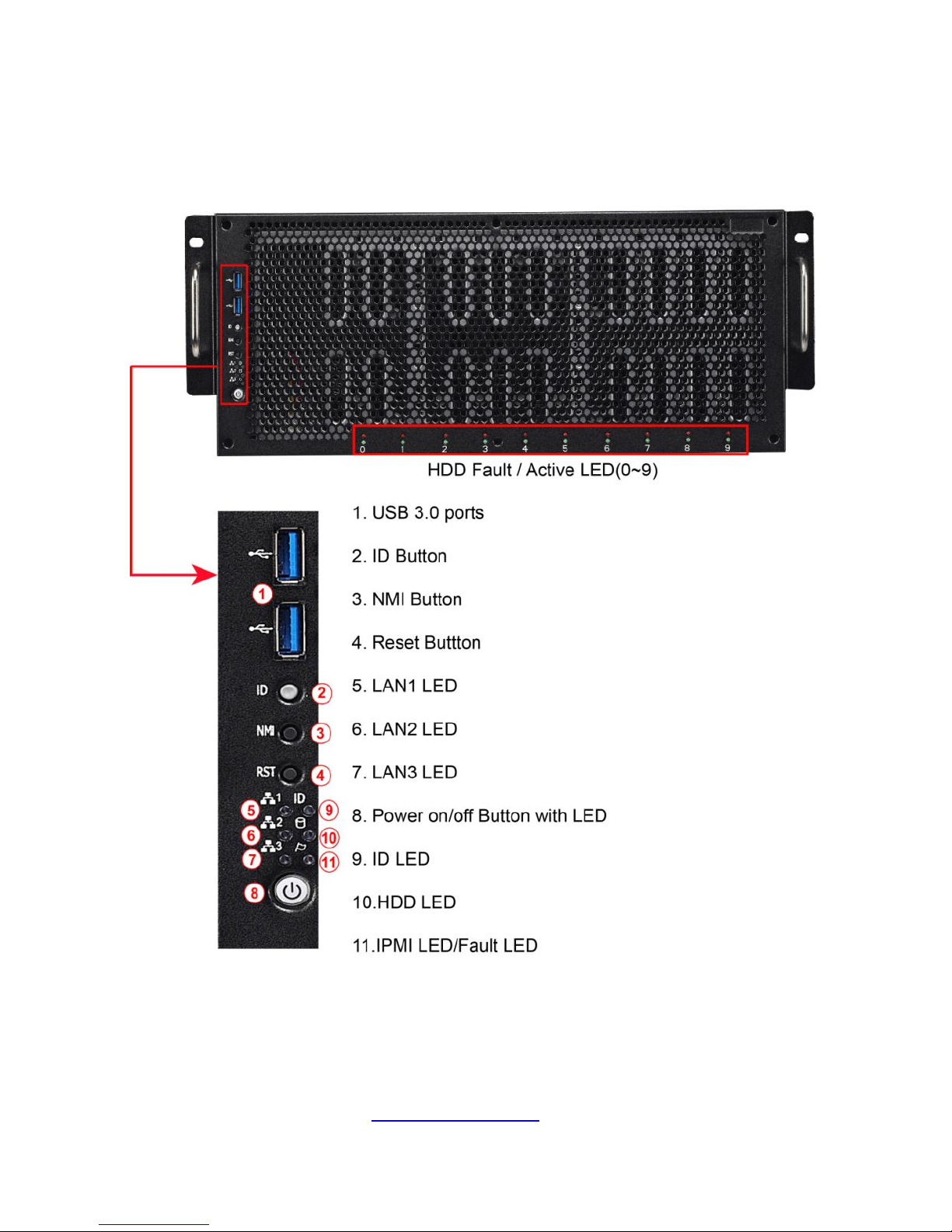
1.5.1 System Front View
Page 24

24
http://www.tyan.com
M1713F77C Front Panel Board
Switch and LED Indication
M1713F77C-FPB R01 LED Definitions
LED
STATE
COLOR
DESCRIPTION
Power
LED
ON
GREEN
system is turn on
ON
GREEN
system is under S1 or S3 state
OFF
OFF
power off
NIC1
Blinking
GREEN
LAN active
ON
GREEN
LAN linked
OFF
OFF
LAN not linked
NIC2
Blinking
GREEN
LAN active
ON
GREEN
LAN linked
OFF
OFF
LAN not linked
NIC3
Blinking
GREEN
LAN active
ON
GREEN
LAN linked
OFF
OFF
LAN not linked
HDD LED
ON
GREEN
HDD accessed
OFF
OFF
NO HDD access
ID LED
ON
BLUE
system identified
OFF
OFF
system no identified
BMC LED
ON
AMBER
Fan fail/Over temperature/Over
voltage/PSU fail
Blinking
AMBER
PSU alert
OFF
OFF
No failure
Button Indication
Power
On/Off
Power up and power off the system(Use a pin)
ID(UID)
Press ID button when the system is AC (Alternating Current) on,
then ID LED will show the system is identified with emitting blue
light. Users from remote
site could also activate ID LED by input a few commands in IPMI,
detailed software support please visit http://www.tyan.com for
latest AST2400 user guide.
RST
Press to reset the system.
Page 25
25
http://www.tyan.com
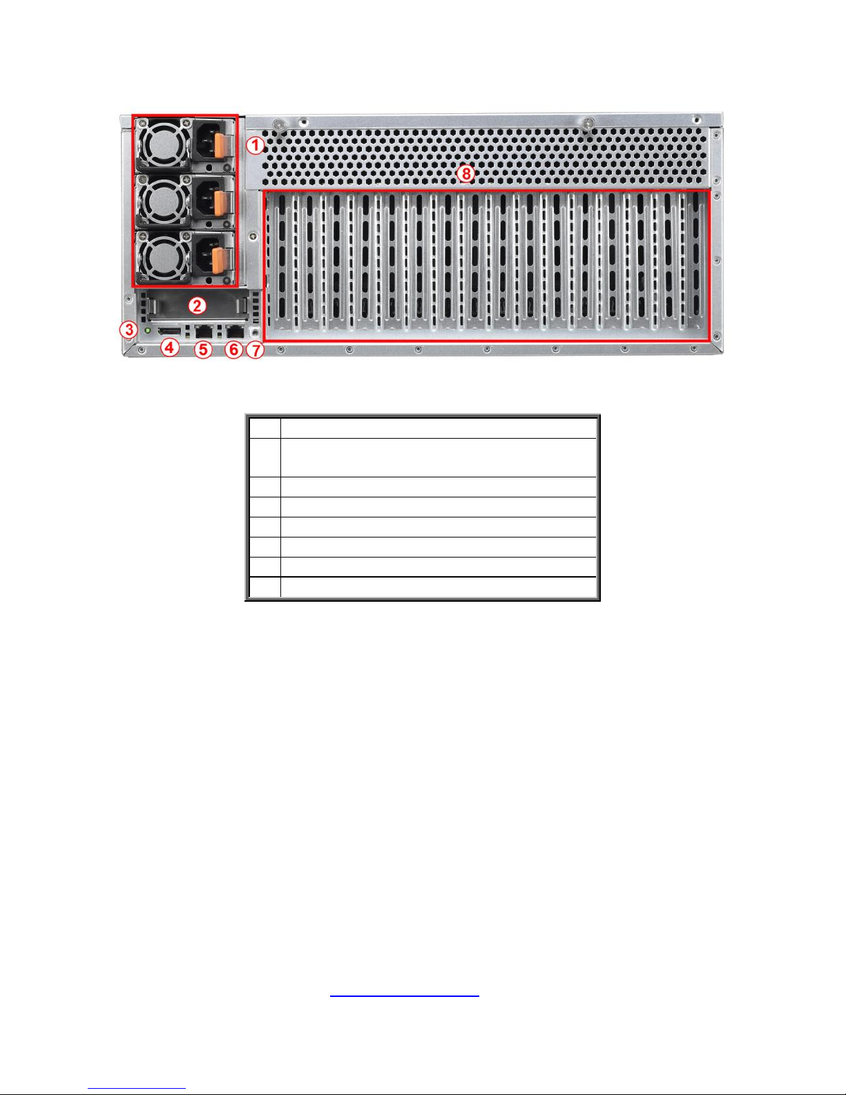
1.5.2 System Rear View
1.
Power Supply Cage
2.
PCIE x 8 Slot for Mezzanine Card
(Optional)
3
ID LED button
4
VGA/USB Port via a dongle cable
5.
LAN2 shared with IPMI
6
LAN1
7
ID LED
8
Expansion Slots
Page 26
26
http://www.tyan.com
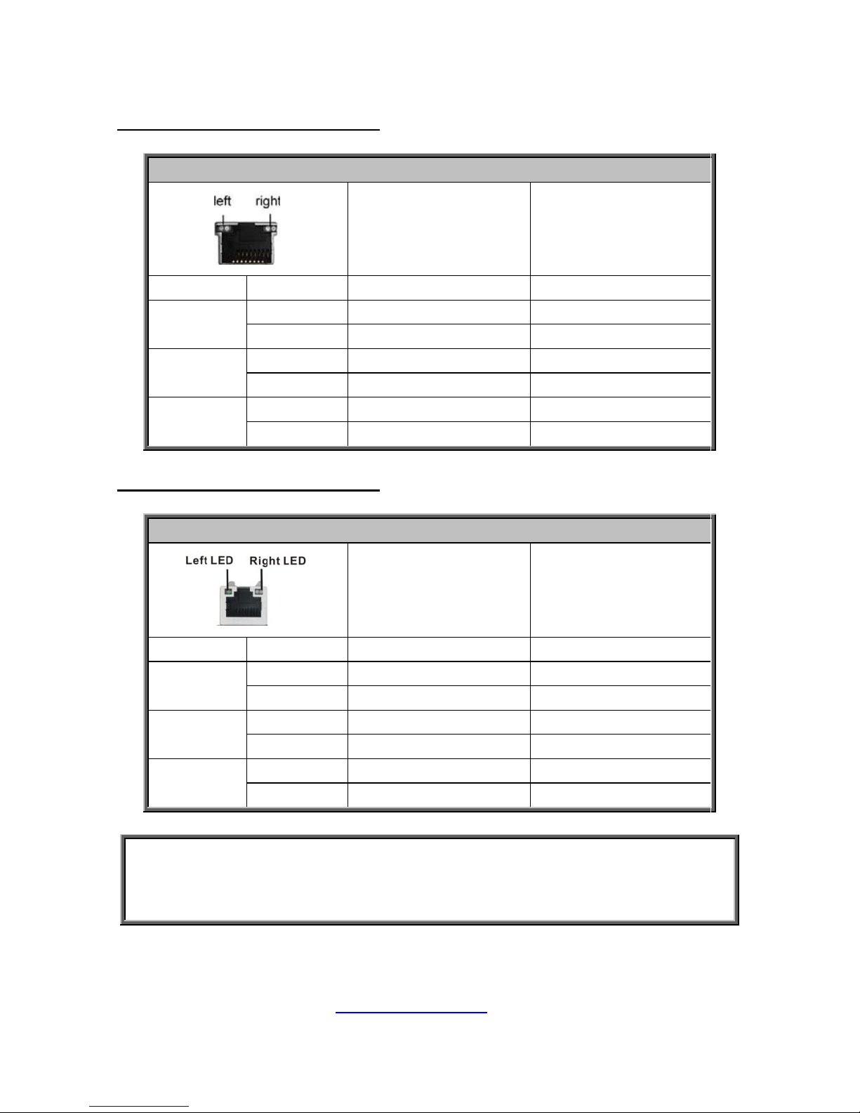
1.5.3 LED Definitions
10Gbps LAN Port LAN Indication
10/100/1000 Mbps LAN Link/Activity LED Scheme
Left LED
(Link/Activity)
Right LED
(Speed)
No Link
OFF
OFF
100 Mbps
Link
Solid Green
Solid Green
Active
Blinking Green
Solid Green
1000 Mbps
Link
Solid Green
Solid Amber
Active
Blinking Green
Solid Amber
(10Gbps)
Link
Solid Amber
Solid Amber
Active
Solid Amber
Solid Amber
10Gbps LAN Port LAN Indication
10/100/1000 Mbps LAN Link/Activity LED Scheme
Left LED
(Link/Activity)
Right LED
(Speed)
No Link
OFF
OFF
10 Mbps
Link
Solid Green
OFF
Active
Blinking Green
OFF
100 Mbps
Link
Solid Green
Solid Green
Active
Blinking Green
Solid Green
1000 Mbps
(1Gbps)
Link
Solid Green
Solid Amber
Active
Blinking Green
Solid Amber
NOTE:
1. When I350-BT2 LAN chip is on, LAN1 and LAN2 can support 10Mbps~1Gbps.
2. When X540-AT2 LAN chip is on, LAN1 and LAN2 can support up to
100Mbps~10Gbps.
Page 27

27
http://www.tyan.com
PSU LED Definitions
Dual-color
Power Supply Condition
Green LED
Amber LED
No AC power to all power supplies
OFF
OFF
Power supply critical event causing
a shutdown failure, OCP, OVP, Fan
Fail, OTP, UVP
OFF
AMBER
Power supply warning events where
the power supply continues to
operate; high temp( inlet
temperature>60 deg (PMBus
reading), or hot spot
temperature>95deg (PMBus
reading), high power, high current,
slow fan(<1200rpm).
OFF
1Hz
Blink AMBER
AC present Only 12VSB on(PS off)
or PS in Smart Redundant state
1Hz
Blink GREEN
OFF
Output ON and OK
ON
OFF
AC cord unplugged
OFF
AMBER
Page 28
28
http://www.tyan.com
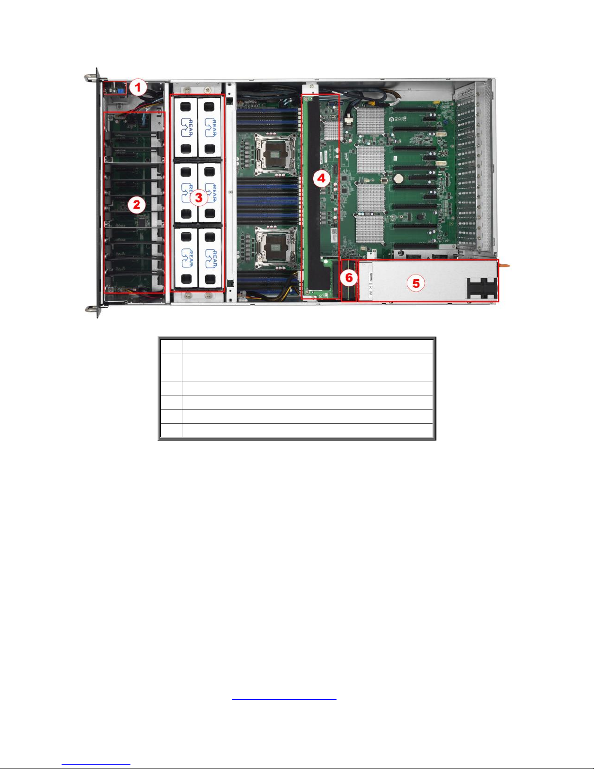
1.5.4 Internal View
1.
M1713F77C-FPB Front Panel Board
2.
Ten 2.5”/3.5” HDD Trays with
M1262F77C-BP6-10 Back Plane Board
3.
Six system Fans
4.
M7059F77-D-PDB Power Distribution Board
5.
Power Supply Cage
6.
M7059F77-D-PBP Power Backplane Board
Page 29
29
http://www.tyan.com
Chapter 2: Setting Up
2.0.1 Before you Begin
This chapter explains how to install the CPUs, CPU heatsinks, memory
modules, and hard drives. Instructions on inserting add on
cards are also given.
2.0.2 Work Area
Make sure you have a stable, clean working environment. Dust and dirt
can get into components and cause malfunctions. Use containers to
keep small components separated. Putting all small components in
separate containers prevents them from becoming lost. Adequate
lighting and proper tools can prevent you from accidentally damaging
the internal components.
2.0.3 Tools
The following procedures require only a few tools, including the
following:
A cross head (Phillips) screwdriver
A grounding strap or an anti-static pad
Most of the electrical and mechanical connections can be disconne-
-cted using your fingers. It is recommended that you do not use nee-
-dlenosed pliers to remove connectors as these can damage the soft
metal or plastic parts of the connectors.
Caution!
1. To avoid damaging the motherboard and associated
components, do not use torque force greater than
7kgf/cm (6.09 lb/in) on each mounting screw for
motherboard installation.
2. Do not apply power to the board if it has been
damaged.
Page 30

30
http://www.tyan.com
2.0.4 Precautions
Components and electronic circuit boards can be damaged by
discharges of static electricity. Working on a system that is connected to
a power supply can be extremely dangerous. Follow the guidelines below
to avoid damage to FT77C-B7079 or injury to yourself.
Ground yourself properly before removing the top cover of the
system. Unplug the power from the power supply and then touch a
safely grounded object to release static charge (i.e. power supply
case). If available, wear a grounded wrist strap. Alternatively,
discharge any static electricity by touching the bare metal chassis
of the unit case, or the bare metal body of any other grounded
appliance.
Avoid touching motherboard components, IC chips, connectors,
memory modules, and leads.
The motherboard is pre-installed in the system. When removing
the motherboard, always place it on a grounded anti-static surface
until you are ready to reinstall it.
Hold electronic circuit boards by the edges only. Do not touch the
components on the board unless it is necessary to do so. Do not
flex or stress circuit boards.
Leave all components inside the static-proof packaging that they
ship with until they are ready for installation.
After replacing optional devices, make sure all screws, springs, or
other small parts are in place and are not left loose inside the case.
Metallic parts or metal flakes can cause electrical shorts.
Page 31

31
http://www.tyan.com
2.1 Installing Motherboard Components
This section describes how to install components on to the motherboard, including
CPUs, memory modules and Add-on cards.
2.1.1 Removing the Chassis Cover
Follow these instructions to remove FT77C-B7079 chassis cover.
1. Remove two screws on the back side as show in the small diagram.
2. Loosen the two Thumb screws on the back side as show in the small
diagram.
2. Push the two buttons in the direction of the arrow, lift the other side top cover
up.
Page 32

32
http://www.tyan.com
3. Unscrew the top cover and release the latches to remove the top cover from
the chassis.
4. Here is the overview after the chassis cover was removed.
5. Unscrew to remove the air duct.
Page 33

33
http://www.tyan.com
2.1.2 Installing the CPU and Heat sink
Follow the steps below on installing CPUs and CPU heat sinks.
1. Locate the CPU socket.
2. Press the lever and unlock the CPU socket.
3. Lift the CPU socket cover up.
Page 34

34
http://www.tyan.com
4. Take out the protection cover and place the CPU to the CPU socket;
5. Close the socket cover.
6. Close the socket levers.
Page 35

35
http://www.tyan.com
7. Close the socket levers.
Page 36

36
http://www.tyan.com
2.1.3 Installing the Memory
Follow these instructions to install the memory modules onto the motherboard.
1. Press the memory slot locking levers in the direction of the arrows as
shown in the following illustration.
2. Align the memory module with the slot. When inserted properly, the
memory slot locking levers lock automatically onto the indentations at
the ends of the module.
NOTE: Before insert the memory, the USB cable3.0 cable should be disconnect first.
Page 37

37
http://www.tyan.com
2.1.4 Installing Expansion Cards
FT77C-B7079 has eight expansion slots which can support GPU (Graphic
Processing Unit) card. Follow these instructions to install expansion cards.
1. Locate the expansion slot on the motherboard, unscrew the bracket from the
slot you want to use and take out the bracket from the slot.
2. Insert the GPU card and secure with 1 screw.
3. Insert the card into the slot and secure it with the screws you removed from
the bracket.
Page 38

38
http://www.tyan.com
4. Connect the cables between the expansion card and the power distribution
board, the connectors you use should match with the slot you add the card
with.
5. Here is the end of the add on card installation.
Page 39

39
http://www.tyan.com
2.1.5 Installing the Mezzanine Card
Follow these instructions to install the Mezzanine Card.
1. Locate the PCI-E Gen3 x8 slot reserved for the Mezzanine card.
2. Push the latches inwards to remove the PCI dummy bracket.
3. Prepare a Mezzanine card (M7059F77-FDR) associated with tray and insert
the tray into the slot.
Page 40

40
http://www.tyan.com
2.1.6 Installing Hard Drives
The FT77C-B7079 supports 10 2.5” and 3.5‟ Hard Drives. Follow these
instructions to install a hard drive.
2.5” Hard Disk Drive
1. Pull the HDD tray out from the chassis.
2. Adjusting the 4 HDD lock to the 2.5” location.
3. Secure the 2 standoff to the 2.5” HDD.
Page 41

41
http://www.tyan.com
4. Stuck the HDD Module to the HDD tray.
5. Reinsert the HDD into the HDD tray
Page 42

42
http://www.tyan.com
3.5” Hard Disk Drive
1. Adjusting the 4 HDD lock to the 3.5” location.
2. Place the 3.5” HDD into the HDD tray.
3. Reinsert the HDD into the HDD tray
Page 43

43
http://www.tyan.com
2.2 Rack Mounting
After installing the necessary components, FT77C-B7079 can be
mounted in a rack using the supplied rack mounting kit.
Rack mounting kit
Rail with Bracket x 2
Mounting Ears x 2
Screw Sack x 1
2.2.1 Installing the Server in a Rack
Follow these instructions to mount the FT77C-B7079 into an industry
standard 19” rack.
Note:
Before mounting FT77C-B7079 in a rack, ensure that all
internal components have been installed and that the unit
has been fully tested. Maintenance can be performed on the
unit while in a rack but it is preferable to install the device in a
fully operational condition.
Screw Sack
A B C
Including:
A: M5 Washer------ 8pcs
B: M5 x 10 ----------8pcs
C: M5 x13 -----------2pcs
Page 44

44
http://www.tyan.com
2.2.2 Installing the inner Rails to the Chassis
1. Screw the mounting ear to each side of FT77 as shown using 3
screws from the supplied screws kit.
2. Push the latch key and draw out the inner rails from sliding rails.
3. Secure inner rails to both sides of the chassis, be sure the five
mounting holes are correctly matched.
Page 45

45
http://www.tyan.com
2.2.3 Installing the Outer Rails to the Rack
1. The nut was needed and prepared by the customer.
2. Secure the outer rail to the rack
Using the rail and 4 M5 x 10
screws with washer for each side.
Page 46

46
http://www.tyan.com
2.2.4 Rack mounting the Server
1. Draw out the middle rail till
the latch position.
2. Lift the chassis and then
insert the inner slide rails
into the middle rails.
3. Push the chassis in and pull the latch key (A). Then push the whole
system into the rack (B).
A
B
Page 47

47
http://www.tyan.com
4. Secure the mounting ears of chassis to the rack with 2 M5 x 13 screws.
Page 48

48
http://www.tyan.com
Chapter 3: Replacing Pre-Installed Components
3.1 Introduction
This chapter explains how to replace the pre-installed components, including the
S7079 Motherboard, M1713F77C-FPB Front Panel Board, M1809F77A-FB Fan
Board, M2210-L8-1F Riser Card, M7059F77-FDR Mezzanine Card,
M1262F77C-BP6-10 HDD Backplane Board, M7059F77-D-PBP Power Backplane
Board,M7059F77-D-PDB Power Distribution Board, System Fan and Power Supply
etc.
3.2 Disassembly Flowchart
The following flowchart outlines the disassembly procedure.
Page 49

49
http://www.tyan.com
3.3 Removing the Cover
Before replacing any parts you must remove the chassis cover. Follow Chapter
2.1.1 to remove the cover of FT77C-B7079.
3.4 Replacing the Power Supply
To replace the power supply follow these instructions.
1. Press the tab as shown in the diagram and pull out the power.
2. Free the power from the power socket.
3. Replace a new single power and reinsert it into the power socket following
the above steps in reverse.
Page 50

50
http://www.tyan.com
3.5 Replacing HDD backplane
Follow these instructions to replace the M1262F77C-BP6-10 HDD Backplane
Board.
1. Remove the 4 screws secure the chassis on the left side.
2. Removing the 4 screws on the other side.
3. Disconnect all the HDD backplane cables.
Page 51

51
http://www.tyan.com
4. Remove the 13 screws secure the HDD cage.
5. Lift up the HDD cage from the chassis
Page 52

52
http://www.tyan.com
3.5.1. HDD Back Plane Board Features
Integrated I/O
(10) SATA HDD Connector connect HDD
(3) SATA Connector connect MB
(2) SATA Mini SAS Connector connect MB
(2)1*4pin power connector
JTAG connector
SGPIO connector
HDD LED connector
LEDs
10 HDD active LEDS
10 HDD fault LEDS
Board size
377*100MM
HDD sequence
Port0
Port1
Port2
Port3
Port4
Port5
Port6
Port7
Port8
Port9
Mini SAS0
SATA0
SATA1
Mini SAS1
Page 53

53
http://www.tyan.com
3.5.2 Pin Definition
J11/J15: SATA Connector
Signal
Pin
Pin
Signal
GND1
P1
P5
RX+
TX+
P2
P6
RX-
TX-
P3
P7
GND3
GND2
P4
SATA0~9: SATA Connector
Signal
Pin
Pin
Signal
NC
P1
P2
NC
NC
P3
P4
GND
GND
P5
P6
NC
VCC5_PRE
P7
P8
VCC5_1
VCC5_2
P9
P10
HDD_PRS_L
SAS_LED
P11
P12
GND
VCC12_PRE
P13
P14
VCC12_1
VCC12_2
P15
S1
GND
SAS_TX+
S2
S3
SAS_TX-
GND
S4
S5
SAS_RX-
SAS_RX+
S6
S7
GND
SAS_Present_L
S8
S9
NC
NC
S10
S11
NC
NC
S12
S13
NC
NC
S14
NC
J13: JTAG Connector
Signal
Pin
Pin
Signal
JTAG_TCK
1
2
GND
JTAG_TDO
3
4
VCC3_3
JTAG_TMS
5
6
NC
NC
7
8
Key
JTAG_TDI
9
10
GND
Page 54

54
http://www.tyan.com
3.6 Replacing Power Distribution Board
Follow these instructions to replace the M7059F77-D-PDB Power Distribution Board.
1. Unscrew the M7059F77-D-PDB Power Distribution Board.
2. Remove the power distribution board for replacement.
3. Follow the steps described earlier in reverse order to reinstall the power
distribution board into the chassis.
Page 55

55
http://www.tyan.com
3.6.1 Power Distribution Board Features
Form Factor
W66.93 x L394 (mm), 8-layer PCB
Connectors
Input:
(1) 24S+6P Connector
Output:
(1) 2x4-pin Power Connector for Fan
Board
(16) 2x4-pin Power Connector for GPU
Page 56

56
http://www.tyan.com
3.6.2 Pin Definition
J1: FCI_PWR_CONN_S24P6_RA to PBP
Definition
Pin
Pin
Definition
VCC12
P11 ~ 18
P21 ~ 28
P31 ~ 38
P41 ~ 48
P51 ~ 58
P61 ~ 68
GND
VCC12
C1~ C6
A1 ~ A6
GND
VCC12
D1 ~ D6
B1 ~ B6
GND
J2: 2×4-Pin ATX Power Connector for FAN Board, the max current is 30A
Signal
Pin
Pin
Signal
GND
1
5
+12V
GND
2
6
+12V
GND
3
7
+12V
GND
4
8
+12V
J3 ~ J18: 2×4-Pin ATX Power Connector for GPU, the max current is 20A
Signal
Pin
Pin
Signal
GND
1
5
+12V
GND
2
6
+12V
GND
3
7
+12V
GND
4
8
+12V
Page 57

57
http://www.tyan.com
3.7 Replace the power backplane Board
Follow these instructions to replace the M7059F77-D-PBP Power Backplane Board.
1. Make sure to take out three power supply units.
2. Disconnect the PBP Power cable.
3. Remove screw secure the PBP board
Page 58

58
http://www.tyan.com
4. Remove the M7059F77-D-PBP bracket.
5. Unscrew the M7059F77-D-PBP from the bracket and replace with a new one.
Follow the steps described earlier in reverse order to reinstall the power backplane
board.
Page 59

59
http://www.tyan.com
3.7.1 Power backplane Features
Form Factor
W80 x L145 (mm), 8-layer PCB
Connectors
(3) DPS-1200TB B(80-plus Platinum)
power connector.
(1) FCI 24S+6P,R/A power connector to
S-S7059GM2NR.
(1) FCI 24S+6P power connector to
M7059F77-D-PDB.
(1) ATX 2Px4 power connector
Page 60

60
http://www.tyan.com
3.7.2 Pin Definition
J1: FCI_PWR_CONN_S24P6_VT to PDB
Definition
Pin
Pin
Definition
VCC12
PA11,PA12,PB11,PB12
PC11,PC12,PD11,PD12
PA21,PA22,PB21,PB22
PC21,PC22,PD21,PD22
PA31,PA32,PB31,PB32
PC31,PC32,PD31,PD32
C1,C2,C3,C4,C5,C6
D1,D2,D3,D4,D5,D6
PA41,PA42,PB41,PB42
PC41,PC42,PD41,PD42
PA51,PA52,PB51,PB52
PC51,PC52,PD51,PD52
PA61,PA62,PB61,PB62
PC61,PC62,PD61,PD62
A1,A2,A3,A4,A5,A6
B1,B2,B3,B4,B5,B6
GND
J5: FCI_PWR_CONN_S24P6_RA to PDB
Signal
Pin
Pin
Signal
VCC12
P11~P18
P21~P28
P31~P38
P41~P48
P51~P58
P61~P68
GND
PS1 PWROK
C1
A1
+12VRS
PS1 PRESENT_N
C2
A2
RETRUN_S
PS1 SMB_ALERT_N
C3
A3
GND
GND
C4
A4
PSON_N
12VSB
C5
A5
NC
GND
C6
A6
NC
PS2 PWROK
D1
B1
PS0 PWROK
PS2 PRESENT_N
D2
B2
PS0
PRESENT_N
PS2 SMB_ALERT_N
D3
B3
PS0
SMB_ALERT_N
SMART_ON
D4
B4
Pull up
SDA
D5
B5
12VSB
SCL
D6
B6
GND
J6: EATX Power Connector 4P*2
Signal
Pin
Pin
Signal
GND
1
5
+12V
GND
2
6
+12V
GND
3
7
+12V
GND
4
8
+12V
Page 61

61
http://www.tyan.com
J2~J4: EATX Power Connector 4P*2
Signal
Pin
Pin
Signal
GND
1
50
GND
GND
2
49
GND
GND
3
48
GND
GND
4
47
GND
GND
5
46
GND
GND
6
45
GND
GND
7
44
GND
GND
8
43
GND
GND
9
42
GND
VCC12
10
41
VCC12
VCC12
11
40
VCC12
VCC12
12
39
VCC12
VCC12
13
38
VCC12
VCC12
14
37
VCC12
VCC12
15
36
VCC12
VCC12
16
35
VCC12
VCC12
17
34
VCC12
VCC12
18
33
VCC12
SDA
19
32
A0
SCL
20
31
A1
PSON_N
21
30
12VSB
SMB_ALERT_N
22
29
SMART_ON
RETRUN_S
23
28
12LS
+12VRS
24
27
PRESENT_N
PWROK
25
26
NC
Page 62

62
http://www.tyan.com
3.8 Replacing the Riser Card
Follow these instructions to replace the M2210-L8-1F Riser Card.
1. Unscrew the power supply cage.
2. Unscrew the riser card bracket from the chassis.
3. Lift out the power supply cage.
Page 63

63
http://www.tyan.com
4. Unscrew the riser card bracket from the chassis.
4. Take out the riser card bracket.
5. Unscrew to replace with a new riser card.
Page 64

64
http://www.tyan.com
3.8.1 Riser card Feature
Form Factor
W31.85 x L94 (mm), 4-layer PCB
Specification
(1) PCI-E Gen3 x8 Slot for non-standard add-on card
Page 65

65
http://www.tyan.com
3.9 Replacing the System Fan Board
1. Lift the fan which you need to replace up.
2. Remove the 4 screws from the fan cage.
Page 66

66
http://www.tyan.com
3. Lift the system fan cage from the chassis.
4. Disconnect all the cables from the M1809F77A-FB fan board.
5. Renew the board and tighten the screw place it back to the chassis
following the above procedures in reverse.
Page 67

67
http://www.tyan.com
3.9.1 M1801F77-Fan Board Features
Form Factor
W81.4 x L312.28 (mm), 4-layer PCB
Specifications
(4) 1x4P ATX Power Connector for Fan
(6) 2x2-pin Power Connector
(1) 2x10-pin System Fan Connector for Motherboard
Fan Sequence
Page 68

68
http://www.tyan.com
3.9.2 Pin Definition
J1/J2/J3/J4/J5/J6: 2x2-pin Power Connector
Definition
Pin
Pin
Definition
GND
1
2
12V
TACH
3
4
PWM
J8: 2×10-Pin System Fan Connector for Motherboard
Definition
Pin
Pin
Definition
Tachometer Input1
1
2
Tachometer Input6
Tachometer Input2
3
4
Tachometer Input7
Tachometer Input3
5
6
Tachometer Input8
Tachometer Input4
7
8
Tachometer Input9
Tachometer Input5
9
10
Tachometer Input10
GND
11
12
KEY
PWM Output2
13
14
PWM Output1
Tachometer Input11
15
16
SMB Data
Tachometer Input12
17
18
SMB Clock
3.3V Standby
19
20
PWM Output3
J7/J9/J10/J11: 1×4-Pin ATX Power Connector for Fan
Definition
Pin
Pin
Definition
+12V
1
2
GND
GND
3
4
NC
Page 69

69
http://www.tyan.com
3.10 Replacing the Front Panel Board
Follow these instructions to replace the M1713F77C-FPB Front Panel Board.
1. Unscrew and disconnect both cables from the front panel board.
2. Prepare a new one to replace. Follow the procedure described earlier in
reverse order to reinsert the front panel board into the chassis.
Page 70

70
http://www.tyan.com
3.10.1 Front Pane Board Features
Integrated I/O
10*2 USB3.0 Header connect to MB
15*2 Header connect to MB
(2) USB3.0 connector
LEDs
1 GREEN/BLUE LED for LAN1 and ID
1 GREEN/GREEN LED for LAN2 and HDD
1 GREEN/AMBER LED for LAN3 and BMC
1 power LED
Board size
97*45.2MM
Page 71

71
http://www.tyan.com
3.10.2 Pin Definition
J34: USB3.0 Header
Definition
Pin
Pin
Definition
VCC_USB
1
2
FP_USB3_RX_N0
FP_USB3_RX_P0
3
4
GND
FP_USB3_TX_N0
5
6
FP_USB3_TX_P0
GND
7
8
USB0-
USB0+
9
10
NC
USB1+
11
12
USB1-
GND
13
14
FP_USB3_TX_P1
FP_USB3_TX_N1
15
16
GND
FP_USB3_RX_P1
17
18
FP_USB3_RX_N1
VCC_USB
19
20
key
J3: 15*2 Header
Definition
Pin
Pin
Definition
PW_LED+
1
2
VCC
key
3
4
ID_LED+
PW_LED-
5
6
ID_LED-
HDD_LED+
7
8
SYS_FAULT1-
HDD_LED-
9
10
SYS_FAULT2-
PWR_SW-
11
12
LAN1_LED+
GND
13
14
LAN1_LED-
RESET-
15
16
ICH_SMBDAT
GND
17
18
ICH_SMBCLK
ID_SW-
19
20
INTRU#
TEMP_SENSOR
21
22
LAN2_LED+
NMI_SW
23
24
LAN2_LED-
NC
25
26
NC
LAN3_LED+
27
28
LAN3_LED-
NC
29
30
NC
Page 72

72
http://www.tyan.com
3.11 Replacing the Motherboard
After removing all of the aforementioned cables, follow these instructions to
remove the motherboard from the chassis.
1. Unscrew the power distribution board bracket.
2. Take out the power distribution board bracket.
Page 73

73
http://www.tyan.com
3. Disconnect all cables.
4. Unscrew the motherboard to lift it out.
Page 74

74
http://www.tyan.com
Chapter 4: Motherboard Information
You are now ready to install your motherboard.
How to install our products right… the first time
The first thing you should do is read this user‟s manual. It contains important
information that will make configuration and setup much easier. Here are some
precautions you should take when installing your motherboard:
(1) Ground yourself properly before removing your motherboard from the
antistatic bag. Unplug the power from your computer power supply and
then touch a safely grounded object to release static charge (i.e. power
supply case). For the safest conditions, MiTAC recommends wearing a
static safety wrist strap.
(2) Hold the motherboard by its edges and do not touch the bottom of the
board, or flex the board in any way.
(3) Avoid touching the motherboard components, IC chips, connectors,
memory modules, and leads.
(4) Place the motherboard on a grounded antistatic surface or on the antistatic
bag that the board was shipped in.
(5) Inspect the board for damage.
The following pages include details on how to install your motherboard into your
chassis, as well as installing the processor, memory, disk drives and cables.
Caution!
3. To avoid damaging the motherboard and associated
components, do not use torque force greater than
7kgf/cm (6.09 lb/in) on each mounting screw for
motherboard installation.
4. Do not apply power to the board if it has been
damaged.
Page 75

75
http://www.tyan.com
4.1 Board Image
S7079
This picture is representative of the latest board revision available at the time of
publishing. The board you receive may not look exactly like the above picture.
Page 76

76
http://www.tyan.com
4.2 Block Diagram
S7079 Block Diagram
Page 77

77
http://www.tyan.com
4.3 Mainboard Mechanical Drawing
Page 78

78
http://www.tyan.com
4.4 Board Parts, Jumpers and Connectors
This diagram is representative of the latest board revision available at the time of
publishing. The board you receive may not look exactly like the above diagram. The
DIMM slot numbers shown above can be used as a reference when reviewing the
DIMM population guidelines shown later in the manual. For the latest board
revision, please visit our web site at http://www.tyan.com.
Page 79

79
http://www.tyan.com
Jumpers & Connectors
Jumper/Connector
Function
J41/J43
4-pin CPU1/CPU0 Fan Connector
J74~J75
6-pin Fan Connector
J25
COM1 Header
J24
COM2 Header
J60
Front Panel Connector
IPMB
IPMB Connector
J35
Fan Connector for BB
J34
Front USB3.0 Header
J36
Power Connector
J38
Chassis Intrusion Header
J58/J59
Type-A USB Header
J42
4-in-1 Mini SAS Connector(SATA0-3)
J32
4-in-1 Mini SAS Connector(SSATA0-3)
J56/J57
Serial ATA Connector(SATA4/SATA5)
J46
ID_LED Button Header
3PHD_5
ME Recovery Mode Jumper
3PHD_2
BIOS Advanced mode Jumper
3PHD_1
BIOS Recovery Mode Jumper
3PHD_3
Security Override Mode Jumper
Clear BTN1
RTC Reset Button for Clear CMOS
PW2/ PW3
SSI 4-pin Power Connector
J19
TYAN Module Header
J3
Display port
SW1/ LED1
D-LED Button/ID LED
SW2
Power on Button
SW3
Reset Button
Jumper Legend
OPEN - Jumper OFF
Without jumper cover
CLOSED - Jumper ON
With jumper cover
Page 80

80
http://www.tyan.com
SYS_FAN3
CPU0_FAN
CPU1_FAN
J60
COM2
SYS_FAN1
SYS_FAN2
J59/J58
COM1
IPMB
Page 81

81
http://www.tyan.com
SYS_FAN1/2/3: 6-Pin FAN Connector
Pin 1 2 3 4
5
6
Signal
GND
P12V
FAN_TACH
FAN_PWM
GND
P12V
Use this header to connect the cooling fan to your motherboard to
keep the system stable and reliable.
CPU0/1_FAN: 4-pin CPU Fan Connectors
Pin 1 2 3 4
Signal
GND
+12V
Tachometer
Fan PWM
(Speed)
Control
J60: Front Panel Connector
Signal
Pin
Pin
Signal
PWRLED+
1
2
FP_PWER(3.3V)
KEY
3
4
IDLED
PWRLED-
5
6
GND
HDDLED+
7
8
FAULT_LED-1
HDDLED-
9
10
FAULT_LED-2
PWR_SW#
11
12
LAN1_ACTLE+
GND
13
14
LAN1_ACTLED-
RST_SW#
15
16
SDA
GND
17
18
SMBCLK
FP_IDLED_BTN_N
19
20
INTRUSION#
FPIO_TEMP_IN
21
22
LAN2_ACTLED+
NMI_SW#
23
24
GND
COM1/2: COM Header
Signal
Pin
Pin
Signal
DCD
1
2
DSR
SIN
3
4
RTS
SOUT
5
6
CTS
DTR
7
8
RI
GND
9
10
KEY
Page 82

82
http://www.tyan.com
J81: USB Front Panel Header (blue)
Signal
Pin
Pin
Signal
VCC
1
2
VCC
USBD-
3
4
USBD-
USBD+
5
6
USBD+
GND
7
8
GND
KEY
9
10
NC
J58/J59: Vertical (Type A) USB Connectors
Pin 1 2 3 4
Signal
VCC
USB
DATA2-
USB
DATA2+
GND
IPMB1: IPMB Connector
Signal
Pin
Pin
Signal
BMC_SMB_DATA
1
2
GND
BMC_SMB_CLK
3
4
NC
Page 83

83
http://www.tyan.com
Caution:
The jumpers are only using for engineering debug. We don‟t
suggest customers change the jumpers‟ position, which may
cause unable to boot device.
3PHD_3
J38
3PHD_1
3PHD_4
3PHD_2
3PHD_5
Page 84

84
http://www.tyan.com
J19: TYAN Module Header
Signal
Pin
Pin
Signal
P3V3
1
2
FRAME_N
LAD0
3
4
KEY
LAD1
5
6
PLT_RST_N
LAD2
7
8
GND
LAD3
9
10
CLK_33M
DBG_SERIRQ
11
12
GND
DBG_PRES_N
13
14
VCC3_AUX
TPM_ADDR_MB
15
16
PCH_TPM_PP_EN
J38: Chassis Intrusion Header
Open
Pin 1 2
Signal
INTRUSION#
GND
Short (Default)
Open: Use this header to trigger the system
chassis intrusion alarm.
Short: Use this header to disable the system
chassis intrusion alarm.
3PHD_1: BIOS Recovery Mode Jumper
Pin
Signal
Pin
Signal
1
NC
2
FM_BIOS_RCVR_BOOT_N
3
GND
Pin 1-2 Closed: Normal Mode (Default)
Pin 2-3 Closed: BIOS Recovery Mode
Page 85

85
http://www.tyan.com
3PHD_2: BIOS Advanced Mode Jumper
Pin
Signal
Pin
Signal
1
PCH_GPIO36_BIOS
_ADV_GND
2
PCH_GPIO36_BIOS_
ADV
3
NC
Pin 1-2 Closed: Normal Mode (Default)
Pin 2-3 Closed: BIOS CORE Tree Execution
3PHD_3: Flash Security Override Jumper
Pin
Signal
Pin
Signal
1
NC
2
MFG_MODE_N
3
GND
Pin 1-2 Closed: Normal Mode (Default)
Pin 2-3 Closed: Security Override
3PHD_5: ME Recovery Mode Jumper
Pin
Signal
Pin
Signal
1
NC
2
FM_ME_RCVR_N
3
GND
Pin 1-2 Closed: Normal Mode (Default)
Pin 2-3 Closed: ME Recovery Mode
Page 86

86
http://www.tyan.com
J56/J57
IDLED_BTN
PWR_BTN
RST_BTN
J46
Page 87

87
http://www.tyan.com
J46: ID LED Button Header
Pin 1 2
Signal
FP_IDLED_BTN_N
GND
J56/J57: SATA3.0 Connector
7
1
1
GND
Connects to the Serial ATA ready
drives via the Serial ATA cable.
2
TXP
3
TXN
4
GND
5
RXN
6
RXP
7
GND
LED1 / IDLED_BTN: ID LED and Button
Pin
Signal
+
P3V3_AUX
-
ID_SW_L
State
Color
Description
On
Blue
System identified
Off
Off
System not identified
NOTE: The ID LED can be activated remotely using IPMI.
Please visit the TYAN Web Site at http://www.tyan.com to download
the latest IPMI Configuration Guide for more details.
Page 88

88
http://www.tyan.com
Some chassis include plastic studs instead of metal. Although the plastic studs are
usable, MiTAC recommends using metal studs with screws that will fasten the
motherboard more securely in place.
Below is a chart detailing what the most common motherboard studs look like and
how they should be installed.
Page 89

89
http://www.tyan.com
4.5 Installing the Memory
Before installing memory, ensure that the memory you have is compatible with the
motherboard and processor. Check the TYAN Web site at http://www.tyan.com for
details of the type of memory recommended for your motherboard.
The Intel® Xeon E5-2600 V3 series (Haswell) processor is a four memory
channels per CPU design with a total of 8 DDR4 channels
This platform supports Registered DDR4 up to 768GB, LR DIMM (Load
Reduced DIMM) DDR4 up to 1,536GB,and LRDIMM 3DS *up to 3,072GB
DDR4 data transfer rates of 1600,1866, and 2133 MT/s are supported
All installed memory will automatically be detected. No jumpers or settings
need to be changed for memory detection.
All memory must be of the same type and density.
Page 90

90
http://www.tyan.com
Recommended Memory Population Table (Single CPU)
Single CPU Installed
(CPU0 only)
Quantity of
memory installed
1 2 3 4 5 6 7 8 9
10
11
12
CPU0_DIMM_A0
√ √ √ √ √ √ √ √ √ √ √
√
CPU0_DIMM_A1
√ √ √ √ √ √ √
√
CPU0_DIMM_A2
√ √ √
√
CPU0_DIMM_B0
√ √ √ √ √ √ √ √ √ √
√
CPU0_DIMM_B1
√ √ √ √ √ √
√
CPU0_DIMM_B2
√ √
√
CPU0_DIMM_C0
√ √ √ √ √ √ √ √ √
√
CPU0_DIMM_C1
√ √ √ √ √
√
CPU0_DIMM_C2
√
√
CPU0_DIMM_D0
√ √ √ √ √ √ √ √
√
CPU0_DIMM_D1
√ √ √
√
CPU0_DIMM_D2
√
NOTE:
1. √ indicates a populated DIMM slot.
2. Install memory in sets of fours for maximum performance. This ensures that all four
memory channels are properly utilized, providing maximum memory bandwidth.
3. Populate the same DIMM type in each channel, specifically
- Use the same DIMM size
- Use the same # of ranks per DIMM
4. Dual-rank DIMMs are recommended over single-rank DIMMs.
Page 91

91
http://www.tyan.com
Recommended Memory Population Table (Dual CPU)
Dual CPU installed (CPU0 and CPU1)
Quantity of
memoryinstalled
2 3 4 5 6 7 8
10
12
14
16
18
20
22
24
CPU0_DIMM_A0
√ √ √ √ √ √ √ √ √ √ √ √ √ √ √
CPU0_DIMM_A1
√ √ √ √ √ √ √ √
CPU0_DIMM_A2
√ √ √ √
CPU0_DIMM_B0
√ √ √ √ √ √ √ √ √ √ √ √ √ √
CPU0_DIMM_B1
√ √ √ √ √ √ √
CPU0_DIMM_B2
√ √ √
CPU0_DIMM_C0
√ √ √ √ √ √ √ √ √ √ √ √
CPU0_DIMM_C1
√ √ √ √ √ √ √
CPU0_DIMM_C2
√ √
CPU0_DIMM_D0
√ √ √ √ √ √ √ √ √ √
CPU0_DIMM_D1
√ √ √ √ √
CPU0_DIMM_D2
√
CPU1_DIMM_A0
√ √ √ √ √ √ √ √ √ √ √ √ √ √ √
CPU1_DIMM_A1
√ √ √ √ √ √ √ √
CPU1_DIMM_A2
√ √ √ √
CPU1_DIMM_B0
√ √ √ √ √ √ √ √ √ √ √ √ √
CPU1_DIMM_B1
√ √ √ √ √ √
CPU1_DIMM_B2
√ √ √
CPU1_DIMM_C0
√ √ √ √ √ √ √ √ √ √ √
CPU1_DIMM_C1
√ √ √ √ √ √
CPU1_DIMM_C2
√ √
CPU1_DIMM_D0
√ √ √ √ √ √ √ √ √
CPU1_DIMM_D1
√ √ √ √ √
CPU1_DIMM_D2
√
Page 92

92
http://www.tyan.com
NOTE:
1. √ indicates a populated DIMM slot.
2. Install memory in sets of fours for maximum performance. This ensures that all four
memory channels are properly utilized, providing maximum memory bandwidth.
3. Populate the same DIMM type in each channel, specifically
- Use the same DIMM size
- Use the same # of ranks per DIMM
4. Dual-rank DIMMs are recommended over single-rank DIMMs.
Intel® Xeon® processor E5-2600v3 product families Support
NOTE 1: 1DPC => One dimm per channel
NOTE 2: 2DPC => Two dimm per channel
Physical Ranks are used to calculate DIMM Capacity.
Supported DRAM Densities are 4Gb, 8Gb.
Page 93

93
http://www.tyan.com
4.6 Installing Add-In Cards
Before installing add-in cards, it‟s helpful to know if they are fully compatible with
your motherboard. For this reason, we‟ve provided the diagrams below, showing the
slots that may appear on your motherboard.
PCI-E Gen3 x16 slot
PCI-E Gen3 x8 slot
PCI-E Gen3 x1 slot
Simply find the appropriate slot for your add-in card and insert the card firmly. Do not
force any add-in cards into any slots if they do not seat in place. It is better to try
another slot or return the faulty card rather than damaging both the motherboard and
the add-in card.
TIP: It‟s a good practice to install add-in cards in a staggered manner rather than
making them directly adjacent to each other. Doing so allows air to circulate within
the chassis more easily, thus improving cooling for all installed devices.
NOTE: You must always unplug the power connector from the motherboard before
performing system hardware changes to avoid damaging the board or expansion
device.
Page 94

94
http://www.tyan.com
4.7 Installing the Power Supply
There are two (2) power connectors on your S7079 motherboard. The S7079
supports EPS 12V power supply.
PWR1: 4-Pin Power Connector
Signal
Pin
Pin
Signal
+12V
1
2
GND
GND
3
4
+5V
PWR2: 4-Pin Power Connector
Signal
Pin
Pin
Signal
+12V
1
2
GND
GND
3
4
+5V
NOTE: You must unplug the power supply before plugging the power
cables to motherboard connectors.
Page 95

http://www.tyan.com
95
Chapter 5: BIOS Setup
5.1 About the BIOS
The BIOS is the basic input/output system, the firmware on the motherboard that
enables your hardware to interface with your software. The BIOS determines what a
computer can do without accessing programs from a disk. The BIOS contains all the
code required to control the keyboard, display screen, disk drives, serial
communications, and a number of miscellaneous functions. This chapter describes
the various BIOS settings that can be used to configure your system.
The BIOS section of this manual is subject to change without notice and is provided
for reference purposes only. The settings and configurations of the BIOS are current
at the time of print and are subject to change, and therefore may not match exactly
what is displayed on screen.
This section describes the BIOS setup program. The setup program lets you modify
basic configuration settings. The settings are then stored in a dedicated,
battery-backed memory (called NVRAM) that retains the information even when the
power is turned off.
To start the BIOS setup utility:
1. Turn on or reboot your system.
2. Press <F2> or <Del> during POST (<Tab> on remote console) to start the
BIOS setup utility.
5.1.1 Setup Basics
The table below shows how to navigate in the setup program using the keyboard.
Key
Function
<F1>
General help window
<ESC>
Exit current menu
arrow keys
Select a different menu
↑or↓ arrow keys
Move cursor up/down
<Tab> / <Shift-Tab>
Cycle cursor up/down
<Home> / <End>
Move cursor to top/bottom of the window
<PgUp> / <PgDn>
Move cursor to next/previous page
<->
Select the previous value/setting of the field
<+>
Select the next value/setting of the field
<F8>
Load Fail Safe default configuration values of the menu
<F3>
Load the Optimal default configuration values of the menu
<F4>
Save and exit
<Enter>
Execute command or select submenu
Page 96

http://www.tyan.com
96
5.1.2 Getting Help
Pressing [F1] will display a small help window that describes the appropriate
keys to use and the possible selections for the highlighted item. To exit the Help
Window, press [ESC] or the [Enter] key again.
5.1.3 In Case of Problems
If you have trouble booting your computer after making and saving the changes with
the BIOS setup program, you can restart the computer by holding the power button
down until the computer shuts off (usually within 4 seconds); resetting by pressing
CTRL-ALT-DEL; or clearing the CMOS.
The best advice is to only alter settings that you thoroughly understand. In particular,
do not change settings in the Chipset section unless you are absolutely sure of what
you are doing. The Chipset defaults have been carefully chosen either by MiTAC or
your system manufacturer for best performance and reliability. Even a seemingly
small change to the Chipset setup options may cause the system to become
unstable or unusable.
5.1.4 Setup Variations
Not all systems have the same BIOS setup layout or options. While the basic look
and function of the BIOS setup remains more or less the same for most systems, the
appearance of your Setup screen may differ from the charts shown in this section.
Each system design and chipset combination requires a custom configuration. In
addition, the final appearance of the Setup program depends on the system
designer. Your system designer may decide that certain items should not be
available for user configuration, and remove them from the BIOS setup program.
NOTE: The following pages provide the details of BIOS menu. Please be aware that
the BIOS menus are continually changing due to continual BIOS updates over the
product lifespan of the motherboard. The BIOS menus provided are current as of the
date when this manual was written. Please visit TYAN‟s website at
http://www.tyan.com for information on BIOS updates available for this specific
motherboard.
Page 97

http://www.tyan.com
97
5.2 Main Menu
In this section, you can alter general features such as the date and time.
Note that the options listed below are for options that can directly be changed within
the Main Setup screen.
BIOS Information
It displays BIOS related information.
Memory Information
This displays the total memory size.
System Date
Adjust the system date.
MM (Months): DD (Days): YYYY (Years)
System Time
Adjust the system clock.
HH (24 hours format): MM (Minutes): SS (Seconds)
Access Level
Read only.
Page 98

http://www.tyan.com
98
5.3 Advanced Menu
This section facilitates configuring advanced BIOS options for your system.
ACPI Settings
System ACPI Parameters.
Hardware Health Configuration
Hardware health Configuration Parameters.
Onboard Device Configuration
Onboard Device Configuration.
PCIe Slot Configuration
Onboard PCIe Slot Configuration
WatchDog Timer Configuration
WatchDog Configuration
ASPEED Super IO Configuration
System Super IO Chip parameters
Page 99

http://www.tyan.com
99
S5 RTC Wake Setting
Enable system to wake from S5 using RTC alarm
Serial Port Console Redirection
Serial Port Console Redirection
PCI Subsystem Settings
PCI, PCI-X and PCI Express Settings
Network stack Configuration
Network stack Settings
CSM Configuration
CSM Configuration, Enable/Disable Option ROM execution setting,etc
Trusted Computing (optional function)
Trusted Computing (TPM) settings.
NOTE: If no TPM chipset is on, the Trusted Computing submenu will not appear.
USB Configuration
USB Configuration Parameters.
Page 100

http://www.tyan.com
100
5.3.1 ACPI Settings
Enable ACPI Auto Configuration
Enable or disable BIOS ACPI Auto Configuration.
Disabled / Enabled
Enable Hibernation
Enables or disables System ability to Hibernate (OS/S4 Sleep State). This option
may not be effective with some OS.
Disabled / Enabled
 Loading...