

Page 1
FT77B-B7059
Service Engineer’s Manual
1
http://www.tyan.com
Page 2

2
http://www.tyan.com
Page 3

PREFACE
Copyright
This publication, including all photographs, illustrations, and software, is
protected under international copyright laws, with all rights reserved.
Neither this manual, nor any material contained herein, may be reproduce d
without written consent of manufacturer.
Copyright 2013 MiTAC International Corporation. All rights reserved. TYAN® is
a registered trademark of MiTAC International Corporation.
Version 1.0
Disclaimer
Information contained in this document is furnished by MiTAC International
Corporation and has been reviewed for accuracy and reliability prior to printing.
MiTAC assumes no liability whatsoever, and disclaims any express or implie d
warranty, relating to sale and/or use of TYAN® products including liability or
warranties relating to fitness for a particular purpose or merchantability. MiTAC
retains the right to make changes to produce descriptions and/or specifications
at any time, without notice. In no event will MiTAC be held liable for any direct
or indirect, incidental or consequential damage, loss of use, loss of data or
other malady resulting from errors or inaccuracies of information conta ined in
this document.
Trademark Recognition
All registered and unregistered trademarks and company names contain ed in
this manual are property of their respective owners including, but not limited to
the following.
TYAN® is a trademark of MiTAC International Corporation.
®
is a trademark of Intel® Corporation.
Intel
®
AMI
, AMIBIOS® and combinations thereof are trademarks of AMI
Technologies.
Microsoft®, Windows® are trademarks of Microsoft Corporation.
®
, PC®, AT® and PS/2® are trademarks of IBM Corporation.
IBM
Winbond
®
is a trademark of Winbond Electronics Corporation.
3
http://www.tyan.com
Page 4

FCC Declaration
A
Notice for the US
Compliance Information Statement (Declaration of
Conformity Procedure) DoC FCC Part 15: This
device complies with part 15 of the FCC Rules
This device complies with Part 15 of the FCC Rules. Operation is subject to
the following conditions:
This device must not cause harmful interference.
This device must accept any interference received, including
interference that may cause undesirable operation.
This equipment has been tested and found to comply with the limits for a
Class A digital device, pursuant to Part 15 of the FCC Rules. These limits
are designed to provide reasonable protection against harmful interference
when the equipment is operated in a commercial environment. This
equipment generates, uses, and can radiate radio frequency energy and, if
not installed and used in accordance with the instruction manual, may cause
harmful interference to radio communications. Operation of this equipment
in a residential area is likely to cause harmful interference in which case the
user will be required to correct the interference at his own expense.
Notice for Canada
This Class A digital apparatus complies with Canadian ICES-003. Cet
appareil numérique de la Classe A est conforme à la norme NMB-003 du
Canada.
CAUTION: Lithium battery included with this board. Do not puncture,
mutilate, or dispose of battery in fire. There will be danger of explosion if
battery is incorrectly replaced. Replace only with the same or equivalent
type recommended by manufacturer. Dispose of used battery according to
manufacturer instructions and in accordance with your local regulations.
Notice for Europe (CE Mark)
This product is in conformity with the Council
Directive 2004/108/EC.
4
http://www.tyan.com
Page 5

About this Manual
This manual is intended for experienced users and integrators with hardware
knowledge of personal computers.
It is aimed to provide you with instructions on installing your TYAN FT77B-B7059.
How this guide is organized
This guide contains the following parts:
Chapter 1: Overview
This chapter provides an introduction to the TYAN FT77B-B7059 barebones and
standard parts list, describes the external components, gives an overview of the
product from different angles.
Chapter 2: Setting Up
This chapter covers procedures on installing the processors, memory modules, hard
drivers and other optional parts.
Chapter 3: Replacing the Pre-installed Components
This chapter covers the removal and replacement procedures for pre-installed
components.
Chapter 4: Motherboard Information
This chapter lists the hardware setup procedures that you need to abide by when
installing system components. It includes description of the jumpers and connectors
on the motherboard.
Chapter5: BIOS Setup
This chapter tells how to change system settings through the BIOS setup menu.
Detailed descriptions of the BIOS parameters are also provided.
Chapter 6: Diagnostics
This chapter introduces some BIOS codes and technical terms to provide better
service for the customers.
Appendix:
This chapter provides the cable connection table, the FRU parts list for ref erence of
system setup, and technical support in case a problem arises with your system.
5
http://www.tyan.com
Page 6

Safety and Compliance Information
Before installing and using TYAN FT77B-B7059, take not e of the following
precautions:
·Read all instructions carefully.
·Do not place the unit on an unstable surface, cart, or stand.
·Do not block the slots and opening on the unit, which are provided for
ventilation.
Only use the power source indicated on the marking labe l. If you are not
·
sure, contact the power company.
·The unit uses a three-wire ground cable, which is equipped with a third pin to
ground the unit and prevent electric shock. Do not defeat the purpose of this
pin. If your outlet does not support this kind of plug, contact your electrician
to replace your obsolete outlet.
·Do not place anything on the power cord. Place the power cord where i t will
not be in the way of foot traffic.
·Follow all warnings and cautions in this manual and on the unit case.
·Do not push objects in the ventilation slots as they may touch high voltage
components and result in shock and damage to the components.
·When replacing parts, ensure that you use parts specified by the
manufacturer.
·When service or repairs have been done, perform routine safety checks to
verify that the system is operating correctly.
·Avoid using the system near water, in direct sunlight, or near a heating
device.
·Cover the unit when not in use.
6
http://www.tyan.com
Page 7
Safety Information
Retain and follow all product safety and operating instructions provided
with your equipment. In the event of a conflict between the instructions in
this guide and the instructions in equipment documentation, follow the
guidelines in the equipment documentation.
Observe all warnings on the product and in the operating instructions. To
reduce the risk of bodily injury, electric shock, fire and damage to the
equipment, observe all precautions included in this guide.
You must become familiar with the safety information in this guide before
you install, operate, or service TYAN products.
Symbols on Equipment
Caution. This symbol indicates a potential hazard.
The potential for injury exists if cautions are not
observed. Consult equipment documentation for
specific details.
Caution. Slide-mounted equipment is not to be
used as a shelf or a work space.
Warning. This symbol indicates the presence of
hazardous energy circuits or electric shock
hazards. Refer all servicing to qualified personnel.
Warning. This symbol indicates the presence of a
hot surface or hot component. If this surface is
contacted, the potential for injury exists.
To reduce risk of injury from a hot component,
allow the surface to cool before touching.
General Precautions
· Follow all caution and warning instructions marked on the equipment and
explained in the accompanying equipment documentation.
Machine Room Environment
· This device is for use only in a machine room or IT room.
· Make sure that the area in which you install the s ystem is properly
ventilated and climate-controlled.
7
http://www.tyan.com
Page 8

· Ensure that the voltage and frequency of your power source match the
voltage and frequency inscribed on the electrical rating label of the
equipment.
· Do not install the system in or near a plenum, air duct, radiator, or heat
register.
· Never use the product in a wet location.
Equipment Chassis
· Do not block or cover the openings to the system.
· Never push objects of any kind through openings in the equipment.
Dangerous voltages might be present.
· Conductive foreign objects can produce a short circuit and cause fire,
electric shock, or damage to your equipment.
· Lift equipment using both hands and with your knees bent.
Equipment Racks
To avoid injury or damage to the equipment:
· Observe local occupational health and safety requirements and guidelines
for manual materials handling.
· Do not attempt to move a rack by yourself; a minimum of two people are
needed to move a rack.
· Do not attempt to move a fully loaded rack. Remove equipment from the
rack before moving it.
· Do not attempt to move a rack on an incline that is greater than 10 degrees
from the horizontal.
· Make sure the rack is properly secured to the floor or ceiling.
· Make sure the stabilizing feet are attached to the rack if it is a single-rack
installation.
· Make sure racks are coupled together if it is a multiple-rack installation.
· Make sure the rack is level and stable before installing an appliance in the
rack.
· Make sure the leveling jacks are extended to the floor.
8
http://www.tyan.com
Page 9

· Make sure the full weight of the rack rests on the leveling jacks.
· Always load the rack from the bottom up. Load the heaviest component in
the rack first.
· Make sure the rack is level and stable before pulling a component out of the
rack.
· Make sure only one component is extended at a time. A rack might become
unstable if more than one component is extended.
To avoid damage to the equipment:
· The rack width and depth must allow for proper serviceability and cable
management.
· Ensure that there is adequate airflow in the rack. Improper installation or
restricted airflow can damage the equipment.
· The rack cannot have solid or restricted airflow doors. You must use a
mesh door on the front and back of the rack or remove the doors to ensure
adequate air flow to the system.
· If you install the Model in a rack, do not place equipment on top of the unit.
It will cause restricted airflow and might cause damage to the equipment.
Make sure the product is properly matted with the rails. Products that are
·
improperly matted with the rails might be unstable.
·
Verify that the AC power supply branch circuit that provides power to the
rack is not overloaded. This will reduce the risk of personal injury, fire, or
damage to the equipment. The total rack load should not exceed 80 percent
of the branch circuit rating. Consult the electrical authority having jurisdiction
over your facility wiring and installation requirements.
· Verify that the AC power supply branch circuit that provides power to the
rack is not overloaded. This will reduce the risk of personal injury, fire, or
damage to the equipment. The total rack load should not exceed 80 percent
of the branch circuit rating. Consult the electrical authority having jurisdiction
over your facility wiring and installation requirements.
Verify that the AC power supply branch circuit that provides power to the
·
rack is not overloaded. This will reduce the risk of personal injury, fire, or
damage to the equipment. The total rack load should not exceed 80 percent
of the branch circuit rating. Consult the electrical authority having jurisdiction
over your facility wiring and installation requirements.
· When use 100V-127VAC input: The system does not support redundant
PSU operation if the total system load exceeds 20A.
9
http://www.tyan.com
Page 10

Equipment Power Cords
· Use only the power cords and power supply units provided with your
system. The system might have one or more power cords.
· Plug the power cord into a grounded (earthed) electrical outlet that is easily
accessible at all times.
· In all European electrical environments, you must ground the Green/Yellow
tab on the power cord. If you do not ground the Green/Yellow tab, it can
cause an electrical shock due to high leakage currents.
Do not place objects on AC power cords or cables. Arrange them so that no
·
one might accidentally step on or trip over them.
· Do not pull on a cord or cable. When unplugging from the electrical outlet,
grasp the cord by the plug.
· To reduce the risk of electrical shock, disconnect all power cords before
servicing the appliance.
Equipment Batteries
· The system battery contains lithium manganese dioxide. If the battery pack
is not handled properly, there is risk of fire and burns.
· Do not disassemble, crush, puncture, short external contacts, or dispose of
the battery in fire or water.
· Do not expose the battery to temperatures higher than 60°C (140°F).
· The system battery is not replaceable. If the battery is replaced by an
incorrect type, there is danger of explosion. Replace the battery only with a
spare designated for your product.
· Do not attempt to recharge the battery.
· Dispose of used batteries according to the instructions of the manufacturer.
Do not dispose of batteries with the general household waste. To forward
them to recycling or proper disposal, use the public collection system or return
them to TYAN, your authorized TYAN partner, or their agents.
10
http://www.tyan.com
Page 11

Equipment Modifications
· Do not make mechanical modifications to the system. TYAN is not
responsible for the regulatory compliance of T YAN equipment that has been
modified.
Equipment Repairs and Servicing
· The installation of internal options and routine maintenance and service of
this product should be performed by individuals who are knowledgeable about
the procedures, precautions, and hazards associated with equipment
containing hazardous energy levels.
· Do not exceed the level of repair specified in the procedures in the product
documentation. Improper repairs can create a safety hazard.
· Allow the product to cool before removing covers and touching internal
components.
· Remove all watches, rings, or loose jewelry when working before removing
covers and touching internal components.
· Do not use conductive tools that could bridge live parts.
· Use gloves when you remove or replace system components; they can
become hot to the touch.
· If the product sustains damage requiring service, disconnect the product
from the AC electrical outlet and refer servicing to an authorized service
provider. Examples of damage requiring service include:
– The power cord, extension cord, or plug has been damaged.
– Liquid has been spilled on the product or an object has fallen into the
product.
– The product has been exposed to rain or water.
– The product has been dropped or damaged.
– The product does not operate normally when you follow the op erating
instructions.
11
http://www.tyan.com
Page 12

12
http://www.tyan.com
Page 13

Table of Contents
Chapter 1: Overview....................................................................... 17
1.1 About the TYAN FT77B-B7059 .............................................. 17
1.2 Product Models ....................................................................... 17
1.3 Features .................................................................................. 18
1.4 Standard Parts List ................................................................. 22
1.4.1 Box Contents.................................................................... 22
1.4.2 Accessories ..................................................................... 22
1.5 About the Product ................................................................... 24
1.5.1 System Front View ........................................................... 24
1.5.2 System Rear View ........................................................... 26
1.5.3 LED Definitions ................................................................ 27
1.5.4 System Top View ............................................................. 29
Chapter 2: Setting Up ..................................................................... 31
2.0.1 Before you Begin ............................................................. 31
2.0.2 Work Area ........................................................................ 31
2.0.3 Tools ................................................................................ 31
2.0.4 Precautions ...................................................................... 32
2.1 Installing Motherboard Components ...................................... 33
2.1.1 Removing the Chassis Cover and Air Duct ..................... 33
2.1.2 Installing the CPU and Heatsink ...................................... 35
2.1.3 Installing the Memory ...................................................... 38
2.1.4 Installing the Expansion Cards ........................................ 39
2.1.6 Installing the Mezzanine Card ......................................... 41
2.1.7 Installing Hard Drives ...................................................... 43
2.2 Rack Mounting ........................................................................ 47
2.2.1 Installing the Server in a Rack ......................................... 47
2.2.2 Installing the inner Rails to the Chassis .......................... 48
2.2.3 Installing the Outer Rails to the Rack .............................. 49
2.2.4 Rack mounting the Server ............................................... 49
Chapter 3: Replacing Pre-Installed Components ........................ 51
3.0.1 Introduction ...................................................................... 51
3.0.2 Disassembly Flowchart .................................................... 51
3.1 Removing the Cover ............................................................... 52
3.2 Replacing the Power Supply .................................................. 52
3.3 Replacing the Power Distribution Board ................................. 53
3.3.1 Power Distribution Board Features ................................. 54
3.3.2 Pin Definitions .................................................................. 55
3.4 Replacing the Power Backplane Board .................................. 56
3.4.1 Power Backplane Board Features ................................... 57
13
http://www.tyan.com
Page 14

3.4.2 Pin Definitions .................................................................. 58
3.5 Replacing the Riser Card ....................................................... 59
3.5.1 Riser Card Features ........................................................ 61
3.6 Replacing the System Fan ..................................................... 62
3.6.1 Fan Board Features ......................................................... 64
3.6.2 Pin Definitions .................................................................. 65
3.7 Replacing the Front Panel Board ........................................... 66
3.7.1 Front Panel Board Features ............................................ 67
3.7.2 Pin Definitions .................................................................. 68
3.8 Replacing the Motherboard .................................................... 69
Chapter 4: Motherboard Information ............................................ 71
4.1 Board Image ........................................................................... 72
4.2 Block Diagram ........................................................................ 73
4.3 Motherboard Mechanical Drawing .......................................... 74
4.4 Board Parts, Jumpers and Connectors .................................. 75
4.5 Thermal Interface Material ...................................................... 85
4.6 Tips on Installing Motherboard in Chassis ............................. 86
4.7 Installing the Memory ............................................................. 88
4.8 PLXPXE8747 LED Definition.................................................. 93
4.9 Finishing Up ............................................................................ 94
Chapter 5: BIOS Setup ................................................................... 95
5.1 About the BIOS ....................................................................... 95
5.1.1 Setup Basics .................................................................... 95
5.1.2 Getting Help ..................................................................... 96
5.1.3 In Case of Problems ........................................................ 96
5.1.4 Setup Variations .............................................................. 96
5.2 Main Menu .............................................................................. 97
5.3 Advanced Menu ...................................................................... 98
5.3.1 PCI Subsystem Settings ................................................ 100
5.3.2 ACPI Settings ................................................................ 102
5.3.3 Trusted Computing ........................................................ 103
5.3.4 CPU Configuration ......................................................... 104
5.3.5 Runtime Error Logging .................................................. 109
5.3.6 SATA Configuration ....................................................... 110
5.3.7 SAS Configuration ......................................................... 111
5.3.8 Onboard Device Configuration ...................................... 112
5.3.9 PCIe Slot Configuration ................................................. 113
5.3.10 USB Configuration ......................................................... 114
5.3.11 Info Report Configuration .............................................. 115
5.3.12 Hardware Health Configuration ..................................... 116
5.3.13 Super IO Configuration .................................................. 118
5.3.14 Serial Port Console Redirection .................................... 120
http://www.tyan.com
14
Page 15

5.4 Chipset Menu ....................................................................... 125
5.4.1 North Bridge .................................................................. 126
5.4.2 South Bridge .................................................................. 133
5.4.3 WatchDog Timer Configuration ..................................... 134
5.5 Boot ..................................................................................... 135
5.5.1 Network Device BBS Priorities ...................................... 137
3.5.2 CSM Parameters ........................................................... 138
5.5.3 Delete Boot Option ........................................................ 140
5.6 Security ................................................................................. 141
5.7 Server Management ............................................................. 142
5.7.1 System Event Log ......................................................... 143
5.7.2 BMC Network Configuration .......................................... 144
5.8 Event Logs ............................................................................ 145
5.9 Save & Exit ........................................................................... 146
Chapter 6: Diagnostics ................................................................ 149
6.1 Flash Utility ........................................................................... 149
6.2 AMIBIOS Post Code (Aptio) ................................................. 150
Appendix I: Cable Connection Tables ........................................ 159
Appendix II: Fan and Temp Sensors .......................................... 161
Appendix III: FRU Parts Table ..................................................... 167
Appendix IV: Technical Support ................................................. 169
15
http://www.tyan.com
Page 16

NOTE
16
http://www.tyan.com
Page 17
Chapter 1: Overview
1.1 About the TYAN FT77B-B7059
Congratulations on your purchase of the TYAN® FT77B-B7059, a highly optimized
4U rack-mountable barebone system. The FT77B-B7059 is designed to support dual
®
Intel
Xeon E5-2600 Series Processors and up to 192GB UDIMM and 384GB
RDIMM, providing a rich feature set and incredible performance. Leveraging
advanced technology from Intel
offering scalable 32 and 64-bit computing, high bandwidth memory design, and
lightning-fast PCI-E bus implementation. The FT77B-B7059 not only empowers your
company in nowadays IT demand but also offers a smooth path for future application
usage.
®
TYAN
also offers the FT77B-B7059 in a version that can support up to ten 2.5” or
3.5” hard drives. The FT77B-B7059 uses TYAN’s latest chassis featuring a rob ust
structure and a solid mechanical enclosure. All of this provides FT77B-B7059 the
power and flexibility to meet the needs of nowadays server application.
®
, the FT77B-B7059 server system is capable of
1.2 Product Models
The system boards within the Tyan MicroServer blades contain different features
and chipsets, which are defined by the following models:
B7059F77BV10R-2T: Intel-based platform
B7059F77BV10R: Intel-based platform
17
http://www.tyan.com
Page 18

1.3 Features
TYAN FT77BB7059 (B7059F77BV10R-2T)
Form Factor 4U Rackmount
Gross Weight 35 kg
System
Front Panel
External Drive
Bay
System Cooling
Configuration
Power Supply
Processor
Chipset PCH Intel C602
Memory
Expansion Slots
Chassis Model FT77B
Dimension (D x W x
H)
Motherboard S7059GM2NR-2T
Buttons (1) RST / (1) ID / (1) PWR w/ LED
LEDs (1) HDD / (2) LAN / (1) ID / (1) IPMI/Warning
I/O Ports (2) USB ports
Type / Q'ty (10) 3.5"/2.5" HDDs
Supported HDD
Interface
FAN (5+1) hot-swap 12cm fans
Efficiency 80 plus Platinum
Redundancy 2+1
Serviceability Hot-swap
Input Range 100-127V AC / 200-240V AC
Output Watts 3,200 Watts
Supported CPU
Series
Socket Type / Q'ty LGA2011 / (2)
Thermal Design
Power (TDP)
wattage
System Bus
Supported DIMM
Qty
DIMM Type / Speed
Capacity
Memory channel 4 Channels per CPU
Memory voltage 1.5V or 1.35V
PCI-E
PCI (1) PCI 32-bit slot
Recommended M7059F77-QDR-2, Dual QSFP IB mezzanie card
30.31" x 17.24" x 6.93" (770 x 438 x 176mm)
(2) SATA 6Gb/s / (4) SATA 3Gb/s / (1) Mini-SAS
(4port w/ SATA 3Gb/s)
Intel Xeon Processor E5-2600/E5-2600 v2 series
processors
Max up to 150W
Up to 8.0/ 7.2/ 6.4 GT/s with Intel QuickPath
Interconnect (QPI) support
(12)+(12) DIMM slots
RDIMM ECC 1866/1600/1333/1066 /
UDIMM/LRDIMM ECC 1866/1600/1333/1066
up to 192GB UDIMM / 384GB RDIMM / 768GB
LRDIMM
(8) PCI-E Gen3 x16 slots / (2) PCI-E Gen3 x8
slots(one for mezzanine card) / (3) PCI-E Gen2 x1
slots
18
http://www.tyan.com
Page 19
TYAN Mezzanie
Card
LAN
Storage SATA
Graphic
I/O Ports
System
Monitoring
Server
Management
BIOS
Operating
System
Regulation
Operating
Environment
RoHS RoHS 6/6 Compliant Yes
Package
Contains
Port Q'ty (2) 10GbE ports (1 port shared with IPMI)
Controller Intel X540-AT2
Connector
Controller Intel C602
Speed (2) 6.0 Gb/s, (8) 3.0 Gb/s
RAID RAID 0/1/10/5 (Intel RST)
Connector type D-Sub 15-pin
Chipset Aspeed AST2300
USB (2) ports (via a dongle cable)
VGA (1) D-Sub 15-pin port (via a dongle cable)
RJ-45 (2) ports (1 port shared with IPMI)
Chipset Aspeed AST2300
Voltage
Temperature Monitors temperature for CPU & memory
LED
Others Watchdog timer support
Onboard Chipset Onboard Aspeed AST2300
AST2300 IPMI
Feature
AST2300 iKVM
Feature
Brand / ROM size AMI / 8MB
Feature
OS supported list Please refer to our Intel OS supported list.
FCC (DoC) Class A
CE (DoC) Yes
Operating Temp. 10° C ~ 35° C (50° F~ 95° F)
Non-operating
Temp.
In/Non-operating
Humidity
Barebone (1) FT77B-B7059 Barebone
Manual (1) Quick Installation Guide
(40Gb/s) / M7059F77-FDR-2, Dual QSFP IB
mezzanie card (56Gb/s)
(2) Mini-SAS (4-ports) + (2) SATA (totally support 10
ports)
Monitors voltage for CPU, memory, chipset & power
supply
Fan fail LED indicator / Over temperature warning
indicator / Fan & PSU fail LED indicator
IPMI 2.0 compliant baseboard management controller
(BMC) / Supports storage over IP and remote
platform-flash / USB 2.0 virtual hub
24-bit high quality video compression / 10/100 Mb/s
MAC interface
Plug and Play (PnP) /PCI2.3 /WfM2.0 /SMBIOS2.3
/PXE boot / ACPI 2.0 power management /Power on
mode after power recovery / User-configurable H/W
monitoring / Auto-configurable of hard disk types
- 40° C ~ 70° C (-40° F ~ 158° F)
90%, non-condensing at 35° C
http://www.tyan.com
19
Page 20
Installation CD (1) TYAN installation CD
Cable Others (1) via a dongle cable
TYAN FT77BB7059 (B7059F77BV10R)
Form Factor 4U Rackmount
Gross Weight 35 kg
System
Front Panel
External Drive
Bay
System Cooling
Configuration
Power Supply
Processor
Chipset PCH Intel C602
Memory
Expansion Slots PCI-E
Chassis Model FT77B
Dimension (D x W x
H)
30.31" x 17.24" x 6.93" (770 x 438 x 176mm)
Motherboard S7059GM2NR
Buttons (1) RST / (1) ID / (1) PWR w/ LED
LEDs (1) HDD / (2) LAN / (1) ID / (1) IPMI/Warning
I/O Ports (2) USB ports
Type / Q'ty (10) 3.5"/2.5" HDDs
Supported HDD
Interface
(2) SATA 6Gb/s / (4) SATA 3Gb/s / (1) Mini-SAS
(4port w/ SATA 3Gb/s)
FAN (5+1) hot-swap 12cm fans
Efficiency 80 plus Platinum
Redundancy 2+1
Serviceability Hot-swap
Input Range 100-127V AC / 200-240V AC
Output Watts 3,200 Watts
Supported CPU
Series
Intel Xeon Processor E5-2600/E5-2600 v2 series
processors
Socket Type / Q'ty LGA2011 / (2)
Thermal Design
Power (TDP)
Max up to 150W
wattage
System Bus
Supported DIMM
Qty
DIMM Type / Speed
Capacity
Up to 8.0/ 7.2/ 6.4 GT/s with Intel QuickPath
Interconnect (QPI) support
(12)+(12) DIMM slots
RDIMM ECC 1866/1600/1333/1066 /
UDIMM/LRDIMM ECC 1866/1600/1333/1066
up to 192GB UDIMM / 384GB RDIMM / 768GB
LRDIMM
Memory channel 4 Channels per CPU
Memory voltage 1.5V or 1.35V
(8) PCI-E Gen3 x16 slots / (2) PCI-E Gen3 x8
slots(one for mezzanine card) / (3) PCI-E Gen2 x1
slots
20
http://www.tyan.com
Page 21
PCI (1) PCI 32-bit slot
Recommended
TYAN Mezzanie
Card
LAN
Storage SATA
Graphic
I/O Ports
System
Monitoring
Server
Management
BIOS
Operating
System
Regulation
Operating
Environment
RoHS RoHS 6/6 Compliant Yes
Port Q'ty (2) GbE ports (1 port shared with IPMI)
Controller Intel I350-BT2
Connector
Controller Intel C602
Speed (2) 6.0 Gb/s, (8) 3.0 Gb/s
RAID RAID 0/1/10/5 (Intel RST)
Connector type D-Sub 15-pin
Chipset Aspeed AST2300
USB (2) ports (via a dongle cable)
VGA (1) D-Sub 15-pin port (via a dongle cable)
RJ-45 (2) ports (1 port shared with IPMI)
Chipset Aspeed AST2300
Voltage
Temperature Monitors temperature for CPU & memory
LED
Others Watchdog timer support
Onboard Chipset Onboard Aspeed AST2300
AST2300 IPMI
Feature
AST2300 iKVM
Feature
Brand / ROM size AMI / 8MB
Feature
OS supported list Please refer to our Intel OS supported list.
FCC (DoC) Class A
CE (DoC) Yes
Operating Temp. 10° C ~ 35° C (50° F~ 95° F)
Non-operating
Temp.
In/Non-operating
Humidity
M7059F77-QDR-2, Dual QSFP IB mezzanie card
(40Gb/s) / M7059F77-FDR-2, Dual QSFP IB
mezzanie card (56Gb/s)
(2) Mini-SAS (4-ports) + (2) SATA (totally support 10
ports)
Monitors voltage for CPU, memory, chipset & power
supply
Fan fail LED indicator / Over temperature warning
indicator / Fan & PSU fail LED indicator
IPMI 2.0 compliant baseboard management controller
(BMC) / Supports storage over IP and remote
platform-flash / USB 2.0 virtual hub
24-bit high quality video compression / 10/100 Mb/s
MAC interface
Plug and Play (PnP) /PCI2.3 /WfM2.0 /SMBIOS2.3
/PXE boot / ACPI 2.0 power management /Power on
mode after power recovery / User-configurable H/W
monitoring / Auto-configurable of hard disk types
- 40° C ~ 70° C (-40° F ~ 158° F)
90%, non-condensing at 35° C
21
http://www.tyan.com
Page 22

Barebone (1) FT77B-B7059 Barebone
Package
Contains
Manual (1) Quick Installation Guide
Installation CD (1) TYAN installation CD
Cable Others (1) via a dongle cable
1.4 Standard Parts List
This section describes FT77B-B7059 package contents and accessories . Open the
box carefully and ensure that all components are present and undamaged. The
product should arrive packaged as illustrated below.
1.4.1 Box Contents
FT77B-B7059 Chassis Kit
(1) 4U chassis
(3) DELTA,DPS-1600CB A,1600W Power Supply (pre-installed)
(6) 120X120X38MM Fan (pre-installed)
(1) S7059 Mother Board (pre-installed)
(1) M1008 Front Panel Board (pre-installed)
(1) M7059F77-D-PDB Power Distribution Board (pre-installed)
(1) M7059F77-D-PBP Power Backplane (pre-installed)
(1) M1809F77A-FB Fan Board (pre-installed)
(1) M2210-L8-1F riser card (pre-installed)
1.4.2 Accessories
If any items are missing or appear damaged, contact your retailer or browse to
TYAN’s website for service: http://www.tyan.com
FT77B-B7059 Accessory Kit
(1) Rail kit
(2) CPU heatsink
(3) US power cord
(3) EU power cord
(1) Mounting ears
(8) 2*3P GPU power cable
(8) 2*4P GPU power cable
(1) Display port cable
(1) 3.5” HDD screw pack
(1) 2.5” HDD screw pack
(1) HDD rubber kit
http://www.tyan.com
22
Page 23

(1) TYAN Installation CD
(8) GPU card holder BKT(Only for GPU card bundle SKU) w/ screw
23
http://www.tyan.com
Page 24
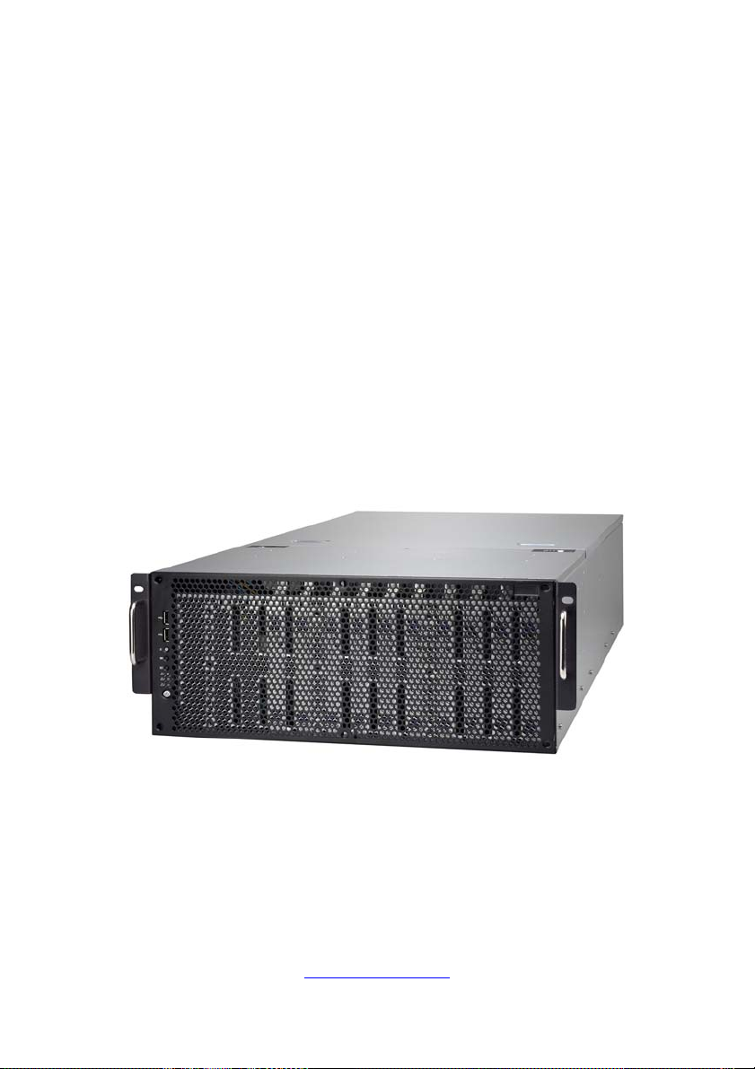
1.5 About the Product
The following views show you the product.
1.5.1 System Front View
24
http://www.tyan.com
Page 25
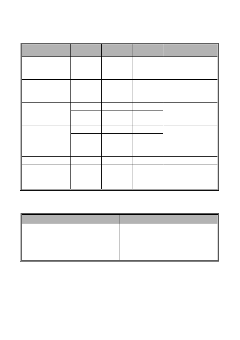
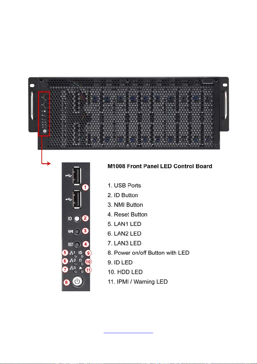
M1008 Front Panel LED Control Board
Switch and LED Indication
Item Status
Access Green Blinking
5. LAN1
Off Link Green Off
Access Green Blinking
6. LAN2
Off Link Green Off
Access Green Blinking
7. LAN3
Off Link Green Off
8. Power
9. ID
10. HDD Access Green Blinking
11. IPMI / Warning
*Warning LED Indication for 2+1 PSU Redundancy System
Power On Green Solid On
Power Off Green Off
Located Blue Solid On
Free Blue Off
Normal Amber Off
Alert Amber Solid On
LED
Color
Behavior Note
Link Green Solid On
Link Green Solid On
Link Green Solid On
BMC & HWM system
alert event
(*) N+1 Redundant
PSU Indication
Status System Warning LED
All PSU present and plug AC cord when
system power on
One of PSU AC lose Amber solid on
One of PSU not present Amber solid on
http://www.tyan.com
25
Off
Page 26
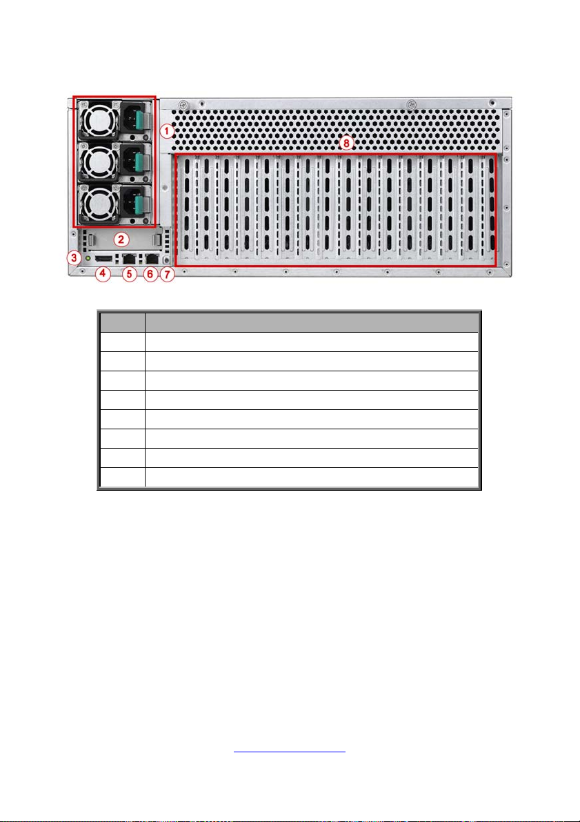
1.5.2 System Rear View
No. Description
1 Power Supply
2 PCIE x8 Slot for Mezzanine Card (optional)
3 ID LED Button
4 VGA/USB Port via a dongle cable
5 LAN2
6 LAN1
7 ID LED
8 Expansion Slots
26
http://www.tyan.com
Page 27
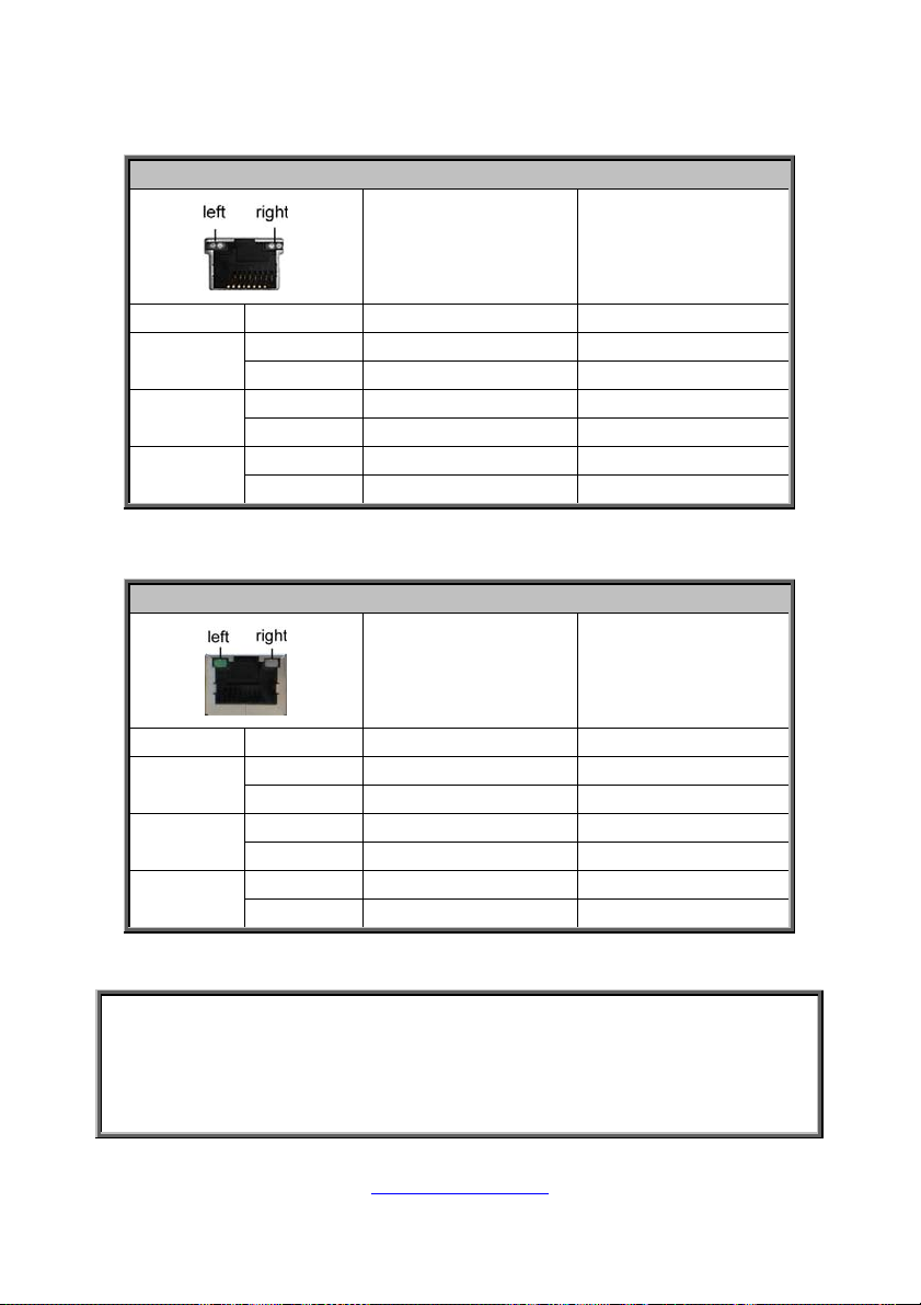
1.5.3 LED Definitions
10Gbps LAN Port LAN Indication
10Gbps LAN Link/Activity LED Scheme
Left LED
(Link/Activity)
LED Color: Green
Right LED
(Speed)
LED Color: Yellow
No Link OFF OFF
100 Mbps
1000 Mbps
(1Gbps)
10 Gbps
Link Green Solid On Green Solid On
Active Green Blinking Green Solid On
Link Green Solid On Yellow Solid On
Active Green Blinking Yellow Solid On
Link Yellow Solid On Yellow Solid On
Active Yellow Blinking Yellow Solid On
1Gbps LAN Port LAN Indication
1Gbps LAN Link/Activity LED Scheme
Left LED
(Link/Activity)
No Link OFF OFF
10 Mbps
100 Mbps
1000 Mbps
(1Gbps)
Link Green Solid On OFF
Active Green Blinking OFF
Link Green Solid On Green Solid On
Active Green Blinking Green Solid On
Link Green Solid On Amber Solid On
Active Green Blinking Amber Solid On
LED Color: Green
Right LED
(Speed)
LED Color: Amber
NOTE: “Left” and “Right” are viewed from the rear panel.
NOTE:
1. When i350 LAN chip is on, LAN1 and LAN2 can support 10Mbps~1Gbps.
2. When X540 LAN chip is on, LAN1 and LAN2 can support up to
100Mbps~10Gbps.
3. Peripheral devices can be plugged straight into any of these ports but
software may be required to complete the installation.
27
http://www.tyan.com
Page 28
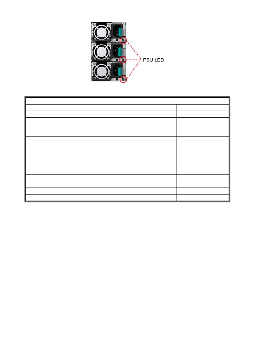
r
A
PSU LED Definitions
Dual-colo
Power Supply Condition Green LED
No AC power to all power supplies OFF OFF
Power supply critical event causing
a shutdown; failure, OCP, OVP,
Fan Fail, OTP, UVP
Power supply warning events
where the power supply continues
to operate; but triggered high
Temperature, high Voltage, high
Current, and low fan rpm critical
limit.
AC present only 12VSB on (PS off)
or PS in Smart Redundant state
Output ON and OK ON OFF
AC cord unplugged OFF ON
OFF ON
OFF
1Hz Blinking Green OFF
mber LED
1Hz Blinking
Amber
Warning: All PSUs have to be AC-ON at the same time before you power on the
system.
28
http://www.tyan.com
Page 29
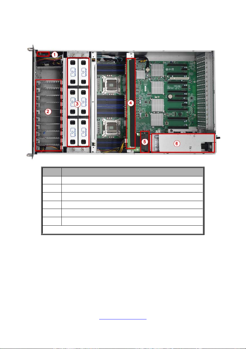
1.5.4 System Top View
No. Description
1 M1008 Front Panel LED Control Board
2 Ten 2.5”/3.5” HDD Trays
3 System Fans
4 M7059F77-D-PDB Power Distribution Board
5 M7059F77-D-PBP Power Backplane Board
6 Power Supply Cage
NOTE: The system is pre-installed with S7059 motherboard.
29
http://www.tyan.com
Page 30

NOTE
30
http://www.tyan.com
Page 31

2.0.1 Before you Begin
This chapter explains how to install the CPUs, CPU heatsinks, memory
modules, and hard drives. Instructions on inserting add on
cards are also given.
2.0.2 Work Area
Make sure you have a stable, clean working environment. Dust and dirt
can get into components and cause malfunctions. Use containers to
keep small components separated. Putting all small components in
separate containers prevents them from becoming lost. Adequate
lighting and proper tools can prevent you from accidentally damaging
the internal components.
2.0.3 Tools
The following procedures require only a few tools, including the
following:
A cross head (Phillips) screwdriver
A grounding strap or an anti-static pad
Most of the electrical and mechanical connections can be disconnected
with your hands. It is recommended that you do not use pliers to remove
connectors as it may damage the soft metal or plastic parts of the
connectors.
Caution!
1. To avoid damaging the motherboard and as sociated
components, do not use torque force greater than
7kgf/cm (6.09 lb/in) on each mounting screw for
motherboard installation.
2. Do not apply power to the board if it has been
damaged.
Chapter 2: Setting Up
31
http://www.tyan.com
Page 32

2.0.4 Precautions
Components and electronic circuit boards can be damaged by
discharges of static electricity. Working on a system that is connected to
a power supply can be extremely dangerous. Follow the guidelines below
to avoid damage to FT77B-B7059 or injury to yourself.
Ground yourself properly before removing the top cover of the
system. Unplug the power from the power supply and then touch a
safely grounded object to release static charge (i.e. power supply
case). If available, wear a grounded wrist strap. Alternatively,
discharge any static electricity by touching the bare metal chassis
of the unit case, or the bare metal body of any other grounded
appliance.
Avoid touching motherboard components, IC chips, connectors,
memory modules, and leads.
The motherboard is pre-installed in the system. When removing
the motherboard, always place it on a gr ounded anti-static surface
until you are ready to reinstall it.
Hold electronic circuit boards by the edges only. Do not touch the
components on the board unless it is necessary to do so. Do not
flex or stress circuit boards.
Leave all components inside the static-proof packaging that they
ship with until they are ready for installation.
After replacing optional devices, make sure all screws, springs, or
other small parts are in place and are not left loose inside the case.
Metallic parts or metal flakes can cause electrical shorts.
CAUTION: Please note that the following illustrations may not look
exactly like the rackmount server you purchased. Therefore, the
illustrations should be held for your reference only.
32
http://www.tyan.com
Page 33

2.1 Installing Motherboard Components
This section describes how to install components onto the motherboard, including
CPUs, memory modules, HDD and PCI-E cards.
2.1.1 Removing the Chassis Cover and Air Duct
Follow these instructions to remove the FT77B-B7059 chassis cover.
1. Loosen the thumb screws.
2. Slide the top cover off.
3. Unscrew the top cover and release the latch es to remove the top cover from
the chassis.
33
http://www.tyan.com
Page 34

4. Unscrew to remove the air duct.
34
http://www.tyan.com
Page 35

2.1.2 Installing the CPU and Heatsink
Follow the steps below on installing CPUs and CPU heatsinks.
1. Locate the CPU socket.
2. Pull the lever slightly away from the socket and then push it to a fully open
position.
3. Push the CPU socket cover to a fully open position.
35
http://www.tyan.com
Page 36

4. Take out the p rotection cap when installing the CPU. Place the CP U into the
socket and make sure that the gold arrow is located in the right direction.
5. Close the CPU socket cover and press the lever down to secure the CPU.
36
http://www.tyan.com
Page 37

6. Position the heatsink on top of the CPU and secure it with 4 screws.
7. Repeat the procedures mentioned earlier to install the second CPU and
heatsink.
37
http://www.tyan.com
Page 38

2.1.3 Installing the Memory
Follow these instructions to install the memory modules onto the motherboard.
1. Locate the memory slots on the motherboard.
2. Press the memory slot locking levers in the direction of the arrows as shown in
the following illustration.
3. Align the memory module with the slot. When inserted properly, the memory
slot locking levers lock automatically onto the indentations at the ends of the
module. Follow the recommended memory population table to install the
other memory modules.
http://www.tyan.com
38
Page 39

2.1.4 Installing the Expansion Cards
FT77B-B7059 has fourteen expansion slots. Only the PCI-E Gen.3 x16 Slots can
support GPU (Graphic Processing Unit) cards. One PCI-E Gen3 x8 Slot is reserved
for Mezzanine card.
PCI-E Gen3 x8 slot (x8 link)
PCI-E Gen3 x16 slot (x16 link)
PCI-E Gen2 x1 slot (x1 link)
PCI 32-bit/33MHz slot
Follow these instructions to install the GPU card.
1. Locate the PCI-E Gen.3 x16 slots on the motherboard. Unscrew to take out
the PCI shields.
2. Insert the card into the slot and secure it with the screws.
http://www.tyan.com
39
Page 40

3. Connect the cables between the expansion card and the power distribution
board, the connectors you use should match with the slot you add the card
with.
4. The installation of the GPU card is now complete.
40
http://www.tyan.com
Page 41

2.1.6 Installing the Mezzanine Card
Follow these instructions to install the Mezzanine Card.
1. Locate the PCI-E Gen3 x8 slot reserved for the Mezzanine card.
2. Push the latches inwards to remove the PCI dummy bracket.
3. Prepare a Mezzanine card (M7059F77-FDR) associated with tray and insert
the tray into the slot.
4. The installation of the Mezzanine card is completed.
http://www.tyan.com
41
Page 42

Caution: The M7059F77A-QDR-2 and M7059F77A-DFR-2
mezzanine cards are equipped with Quad Small Form-factor
Pluggable (QSFP) modules. Only QSFPs should be installed into the
cards.
42
http://www.tyan.com
Page 43

2.1.7 Installing Hard Drives
The FT77B-B7059 can support (10) 2.5” or 3.5” hard drives.
2.5” Hard Disk Drive
The FT77B-B7059 supports up to ten internal 2.5” SATAII hard drives. Follow these
instructions to install a hard drive.
1. Lift up the 2.5’’ HDD tray from the chassis.
2. Insert HDD rubber into the 2.5” HDD tray as shown.
3. Place a 2.5’’ hard drive into the HDD tray and secure it using four flat screws.
43
http://www.tyan.com
Page 44

4. Reinsert the HDD tray into the chassis and connect the Mini SAS cable and
SATA power cable to the 2.5” HDD tray.
44
http://www.tyan.com
Page 45

3.5” Hard Disk Drive
The FT77B-B7059 can support up to ten internal 3.5” SATAII hard drives. Follow
these instructions to install a hard drive.
1. Lift up the 3.5’’ HDD tray from the chassis.
2. Unscrew to remove the 2.5” HDD tray bracket.
3. Insert HDD rubber into the 3.5” HDD tray as shown.
4. Place a 3.5’’ hard drive into the HDD tray and secure it using four flat
screws.
http://www.tyan.com
45
Page 46

5. Reinsert the HDD tray into the chassis and connect the Mini SAS cable
and SATA power cable to the 3.5” HDD tray.
46
http://www.tyan.com
Page 47

2.2 Rack Mounting
After installing the necessary components, FT77B-B7059 can be mounted in a
rack using the supplied rack mounting kit.
Rack Mount Kit
Rail with Bracket x 2
Mounting Ears x 2
Screw Sack x 1
Screw Sack
A B C
A: M5 Washer------ 8pcs
B: M5 x 10 ----------8pcs
2.2.1 Installing the Server in a Rack
Follow these instructions to mount the FT77B-B7059 into an industry standard
19” rack.
NOTE: Before mounting the TYAN FT77B-B7059 in a rack, ensure that all
internal components have been installed and that the unit has been fully tested.
However, to make the installation easier, we suggest that you remove all HDD
trays before you insert the chassis to the rack.
C: M5 x13 -----------2pcs
47
http://www.tyan.com
Page 48

2.2.2 Installing the inner Rails to the Chassis
1. Screw the mounting ear to each side of FT77A as shown using 3
screws from the supplied screws kit.
2. Push the latch key and draw out the inner rails from sliding rails.
3. Secure inner rails to both sides of the chassis, be sure the five
mounting holes are correctly matched.
48
http://www.tyan.com
Page 49

2.2.3 Installing the Outer Rails to the Rack
Secure the outer rail to the rack
using the rail and four M5 x 10
screws with washer for each side.
2.2.4 Rack mounting the Server
1. Draw out the middle rail till
the latch position.
2. Lift the chassis and then
insert the inner slide rails
into the middle rails.
49
http://www.tyan.com
Page 50

3. Push the chassis in and pull the latch key (A). Then push the whole
system into the rack (B).
B
A
4. Secure the mounting ears of chassis to the rack with two M5 x 13
screws.
Note:
To avoid injury, it is strongly recommended that two people
lift the TYAN FT77B-B7059 into the place while a third
person screws it to the rack.
50
http://www.tyan.com
Page 51

Chapter 3: Replacing Pre-Installed Components
3.0.1 Introduction
This chapter explains how to replace the pre-installed components, including the
S7059 Motherboard, M1008 Front Panel LED Control Board, M1809F77A-FB Fan
Board, M2210-L8-1F Riser Card, M7059F77-FDR Mezzanine Card, M1257F65-BP
HDD Backplane Board, M7059F77-D-PBP Power Backplane Board,
M7059F77-D-PDB Power Distribution Board, System Fan and Power Supply etc.
3.0.2 Disassembly Flowchart
The following flowchart outlines the disassembly procedures.
http://www.tyan.com
51
Page 52

3.1 Removing the Cover
Before replacing any parts you must remove the chassis cover. Follow Section 2.1.1
Removing the Chassis Cover (page 33) to remove the cover of the FT77B-B7059.
3.2 Replacing the Power Supply
The system has three pre-installed Power Supply Units. Please unplug the power
cord before you follow these instructions to replace the power supply units.
1. Press the latch to pull the power supply out.
2. After replacing a new power supply, press the latch to push the power supply
back into the chassis.
52
http://www.tyan.com
Page 53

3.3 Replacing the Power Distribution Board
Follow these instructions to replace the M7059F77-D-PDB Power Distribution Board.
1. Unscrew the M7059F77-D-PDB and disconnect the 8-pin power cable.
2. Remove the power distribution board for replacement.
3. Follow the steps described earlier in reverse order to reinstall the power
distribution board into the chassis.
53
http://www.tyan.com
Page 54

3.3.1 Power Distribution Board Features
Form Factor
Connectors
W66.93 x L394 (mm), 8-layer PCB
Input:
(1) 24S+6P Connector
Output:
(1) 2x4-pin Power Connector for Fan Board
(16) 2x4-pin Power Connector for GPU
54
http://www.tyan.com
Page 55

3.3.2 Pin Definitions
J1: FCI_PWR_CONN_S24P6_RA to PBP
Definition Pin Pin Definition
VCC12
VCC12 C1 ~ C6 A1 ~ A6 GND
VCC12 D1 ~ D6 B1 ~ B6 GND
P11 ~ 18
P21 ~ 28
P31 ~ 38
J2: 2×4-Pin ATX Power Connector for FAN Board, the max current is 30A
Definition Pin Pin Definition
GND 1 5 +12V
GND 2 6 +12V
GND 3 7 +12V
GND 4 8 +12V
J3 ~ J18: 2×4-Pin ATX Power Connector for GPU, the max current is 20A
Definition Pin Pin Definition
GND 1 5 +12V
GND 2 6 +12V
GND 3 7 +12V
GND 4 8 +12V
P41 ~ 48
P51 ~ 58
P61 ~ 68
GND
55
http://www.tyan.com
Page 56

3.4 Replacing the Power Backplane Board
Follow these instructions to replace the M7059F77-D-PBP Power Backplane Board.
1. Make sure to take out three power supply units.
2. Remove the M7059F77-D-PBP bracket.
3. Unscrew the M7059F77-D-PBP from the bracket and replace with a new one.
Follow the steps described earlier in reverse order to reinstall the power
backplane board.
56
http://www.tyan.com
Page 57

3.4.1 Power Backplane Board Features
Form Factor
Connectors
W80 x L145 (mm), 8-layer PCB
Input:
(3) Power Connector for GPU
Output:
(1) 24S+6P R/A Connector for Motherboard
(1) 24S+6P Connector for M7059F77-D-PDB
(1) 2x4-pin ATX Power Connector
57
http://www.tyan.com
Page 58

3.4.2 Pin Definitions
J1: FCI_PWR_CONN_S24P6_RA to PBP
Definition Pin Pin Definition
VCC12
VCC12 C1 ~ C6 A1 ~ A6 GND
VCC12 D1 ~ D6 B1 ~ B6 GND
P11 ~ 18
P21 ~ 28
P31 ~ 38
J2: 2×4-Pin ATX Power Connector for FAN Board, the max current is 30A
Definition Pin Pin Definition
GND 1 5 +12V
GND 2 6 +12V
GND 3 7 +12V
GND 4 8 +12V
J3 ~ J18: 2×4-Pin ATX Power Connector for GPU, the max current is 20A
Definition Pin Pin Definition
GND 1 5 +12V
GND 2 6 +12V
GND 3 7 +12V
GND 4 8 +12V
P41 ~ 48
P51 ~ 58
P61 ~ 68
GND
58
http://www.tyan.com
Page 59

3.5 Replacing the Riser Card
Follow these instructions to replace the M2210-L8-1F Riser Card.
1. Unscrew the power supply cage.
2. Lift out the power supply cage.
59
http://www.tyan.com
Page 60

3. Unscrew the riser card bracket from the chassis.
4. Take out the riser card bracket.
5. Unscrew to replace with a new riser card.
6. Reinstall the riser card into the chassis following the steps in reverse.
60
http://www.tyan.com
Page 61

3.5.1 Riser Card Features
Form Factor
Specifications
W31.85 x L94 (mm), 4-layer PCB
(1) PCI-E Gen3 x8 Slot for non-standard add-on card
61
http://www.tyan.com
Page 62

3.6 Replacing the System Fan
Follow these instructions to replace the system fans.
1. Remove the power distribution board bracket.
2. Pull out all fans.
3. Unscrew the fan cage.
62
http://www.tyan.com
Page 63

4. Lift up the fan cage from the chassis.
5. Disconnect all cables attached to the M1809F77A-FB Fan Board.
6. Unscrew to replace the fan board with a new one. Follow the steps described
earlier in reverse order to reinstall the fans and fan cage into the chassis.
63
http://www.tyan.com
Page 64

3.6.1 Fan Board Features
Form Factor
Specifications
FAN Sequence
W81.4 x L312.28 (mm), 4-layer PCB
(4) 1x4P ATX Power Connector for Fan
(6) 2x2-pin Power Connector
(1) 2x10-pin System Fan Connector for Motherboard
64
http://www.tyan.com
Page 65

3.6.2 Pin Definitions
J1/J2/J3/J4/J5/J6: 2x2-pin Power Connector
Definition Pin Pin Definition
GND 1 2 +12V
TACH 3 4 PWM
J8: 2×10-Pin System Fan Connector for Motherboard
Definition Pin Pin Definition
Tachometer Input1 1 2 Tachometer Input6
Tachometer Input2 3 4 Tachometer Input7
Tachometer Input3 5 6 Tachometer Input8
Tachometer Input4 7 8 Tachometer Input9
Tachometer Input5 9 10 Tachometer Input10
GND 11 12 KEY
PWM Output2 13 14 PWM Output1
Tachometer Input11 15 16 SMB Data
Tachometer Input12 17 18 SMB Clock
3.3V Standby 19 20 PWM Output3
J7/J9/J10/J11: 1×4-Pin ATX Power Connector for Fan
Definition Pin Pin Definition
+12V 1 2 GND
GND 3 4 NC
65
http://www.tyan.com
Page 66

3.7 Replacing the Front Panel Board
Follow these instructions to replace the M1008 Front Panel LED Control Board.
1. Unscrew and disconnect both cables from the front panel board.
2. Prepare a new one to replace. Follow the procedure described earlier in
reverse order to reinsert the front panel board into the chassis.
66
http://www.tyan.com
Page 67

3.7.1 Front Panel Board Features
Form Factor
Specifications
W45.21 x L97 (mm), 4-layer PCB
Support Power Button, Reset Button, NMI Switch, ID LED
Button
Support Power Standby Function
Power ON: Power LED solid green on
Power Standby: Power LED blinking green)
Support dual USB Ports
Power LED, HDD LED, ID LED, 3 LAN LEDs & BMC LED
(1) 2x15-pin Header for SSI FP (Pitch 2.54)
67
http://www.tyan.com
Page 68

3.7.2 Pin Definitions
J1: USB Header
Definition Pin Pin Definition
VCC 1 2 VCC
USB1- 3 4 USB2USB1+ 5 6 USB2+
GND 7 8 GND
KEY 9 10 GND
J3: New SSI FP
Definition Pin Pin Definition
PW_LED+ 1 2 VCC
KEY 3 4 ID_LED+
PW_LED- 5 6 ID_LEDHDD_LED+ 7 8
HDD_LED- 9 10
PWR_SW- 11 12
GND 13 14
RESET- 15 16
GND 17 18
ID_SW- 19 20
TEMP_SENSOR 21 22
NMI_SW 23 24
NC 25 26
LAN3_LED+ 27 28
NC 29 30
68
http://www.tyan.com
Page 69

3.8 Replacing the Motherboard
Follow these instructions to replace the motherboard.
1. Unscrew the power distribution board bracket.
2. Take out the power distribution board bracket.
69
http://www.tyan.com
Page 70

3. Disconnect all cables.
4. Unscrew the motherboard to lift it out.
5. Replace the motherboard and follow the procedures described earlier in
reverse order to reinstall.
70
http://www.tyan.com
Page 71

Chapter 4: Motherboard Information
You are now ready to install your motherboard.
How to install our products right… the first time
The first thing you should do is read this user’s manual. It contains important
information that will make configuration and setup much easier. Here are some
precautions you should take when installing your motherboard:
(1) Ground yourself properly before removing your motherboard from the
antistatic bag. Unplug the power from your computer power supply and
then touch a safely grounded object to release static charge (i.e. power
supply case). For the safest conditions, MiTAC recommends wearing a
static safety wrist strap.
(2) Hold the motherboard by its edges and do not touch the bottom of the
board, or flex the board in any way.
(3) Avoid touching the motherboard components, IC chips, connectors,
memory modules, and leads.
(4) Place the motherboard on a g roun ded antist atic surface or on the antist ati c
bag that the board was shipped in.
(5) Inspect the board for damage.
The following pages include details on how to install your motherboard into your
chassis, as well as installing the processor, memory, disk drives and cables.
Caution!
1. To avoid damaging the motherboard and as sociated
components, do not use torque force greater than
7kgf/cm (6.09 lb/in) on each mounting screw for
motherboard installation.
2. Do not apply power to the board if it has been
damaged.
71
http://www.tyan.com
Page 72

4.1 Board Image
S7059
This picture is representative of the latest board revision available at the time of
publishing. The board you receive may not look exactly like the above picture.
NOTE:
SATA #0 ~ #3 (AHCI, SATA 6Gb/s from #0, #1; SATA 3Gb/s from #2, #3) use
vertical mini SAS connector (marked with red).
The associate cables are labeled as #1, #2, #3 and #4.
#1 and #2 are sourced from SATA #0 and #1, running at SATA 6Gb/s.
#3 and #4 are sourced from SATA #2 and #3, running at SATA 3Gb/s.
SATA #4~ #5 (AHCI, SATA 3Gb/s) use standard SATA connectors (marked with
yellow).
SATA #0 ~ #3 (SCU#0, SATA 3Gb/s) use horizontal mini SAS connector (marked
with red but de-populated)
72
http://www.tyan.com
Page 73

4.2 Block Diagram
S7059 Block Diagram
73
http://www.tyan.com
Page 74

4.3 Motherboard Mechanical Drawing
74
http://www.tyan.com
Page 75

4.4 Board Parts, Jumpers and Connectors
This diagram is representative of the latest board revision available at the time of
publishing. The board you receive may not look exactly like the above diagram. The
DIMM slot numbers shown above can be used as a reference when reviewing the
DIMM population guidelines shown later in the manual. For the latest board
revision, please visit our web site at http://www.tyan.com.
75
http://www.tyan.com
Page 76

Jumpers & Connectors
Jumper/Connector Function
J5 IDLED Switch Header
J18 Flash Security Override Header
J26 SATA SGPIO Header for BB HD Board
J31 IPMB Connector
J32
J35 Front Fan Connector Reserved for Barebone
J36 Power Connector
J38 Chassis Intrusion Header
J39 USB Front Panel Header
J41/J43 CPU0 / CPU1 FAN Connector
J42
J56(SATA4) / J57(SATA5) SATA2.0 Connector
J58/J59 Vertical Type-A USB Connector
J60 Front Panel Header
J73/J74/J75/J76 4-pin FAN Connector
JP5 Clear CMOS Jumper
JP6 BIOS Recovery Mode Jumper
JP7 ME Firmware Update Jumper
PW1 4-pin HDD Power Connector
SW1 / LED1 ID LED Button / ID LED
Jumper Legend
Mini SAS Connector (SATA0~3)
SATA0~3: SATA 2.0 Connector
Vertical Mini SAS Connector (SATA0~3)
SATA0~1: SATA3.0 Connector
SATA2~3: SATA2.0 Connector
OPEN - Jumper OFF Without jumper cover
CLOSED - Jumper ON With jumper cover
76
http://www.tyan.com
Page 77

J76
J5
J43
J75
J74
J41
J73
J38
77
http://www.tyan.com
J60
Page 78

J41J43//J73/J74/J75/J76: 4-Pin FAN Connector
Pin 1 2 3 4
Signal GND VCC Tachometer PWM
Use this header to connect the cooling fan to your motherboard to keep the
system stable and reliable.
J41: CPU0_FAN J43: CPU1_FAN J73: SYS_FAN_4
J74: SYS_FAN_3 J75: SYS_FAN_2 J76: SYS_FAN_1
J5: IDLED Switch Header
Pin 1 2
Signal FP IDLED Switch
J38: Chassis Intrusion Header
open
Short (Default)
J60: Front Panel Header
PWRLED-(GND) 5 6 ID_LED-(GND)
Power Switch+ 11 12 LAN1_ACTIVE_LED+
Power Switch-(GND) 13 14 LAN1_ACTIVE_LED-
Reset Switch+ 15 16 SMB_DATA
Reset Switch-(GND) 17 18 SMB_CLK
TEMP Sensor 21 22 LAN2_ACTIVE_LED+
FP IDLED Switch
(GND)
Pin 1 2
Signal Intrusion Switch
Open: Use this header to trigger the system chassis
intrusion alarm.
Short: Use this header to disable the system chassis
intrusion alarm.
Signal Pin Pin Signal
PWRLED+ 1 2 FP Power(3.3V standby)
KEY 3 4 ID_LED+
HD_LED+ 7 8 Fault LED1-
HD_LED- 9 10 Fault LED2-
ID Switch+ 19 20 INTRUDER#
NMI Switch# 23 24 LAN2_ACTIVE_LED -
Intrusion Switch
(GND)
78
http://www.tyan.com
Page 79

J31
J35
JP5
J39
79
http://www.tyan.com
Page 80

J39: USB Front Panel Header (blue)
Signal Pin Pin Signal
USB 5V Power 1 2 USB 5V Power
USB Data- 3 4 USB Data-
USB Data+ 5 6 USB Data+
GND 7 8 GND
KEY 9 10
J35: Front Fan Connector (Reserved for Barebone Fan Board)
Signal Pin Pin Signal
Tachometer input1 1 2 Tachometer input6
Tachometer input2 3 4 Tachometer input7
Tachometer input3 5 6 Tachometer input8
Tachometer input4 7 8 Tachometer input9
Tachometer input5 9 10 Tachometer input10
GND 11 12 KEY
PWM output2 13 14 PWM output1
Tachometer input11 15 16 SMB DATA
Tachometer input12 17 18 SMB CLK
3.3V Standby 19 20 PWM output3
J31: IPMB Connector
Signal Pin Pin Signal
SMB_SDA2 1 2 GND
SMB_SCL2 3 4 NC
NC
JP5: Clear CMOS Jumper
You can reset the CMOS settings by using this jumper. This can be
useful if you have forgotten your system/setup password, or need to
clear the system BIOS setting.
Normal (Default)
Clear CMOS
1. Power off system and disconnect power connectors from the
motherboard.
2. Remove the jumper from Pin_1 and Pin_2 (Default setting).
3. Move the jumper cap to close Pin_2 and Pin_3 for several seconds
to Clear CMOS.
4. Put jumper cap back to Pin_1 and Pin_2 (Default setting).
5. Reconnect power connectors to the motherboard and power on
system.
80
http://www.tyan.com
Page 81

SW1
LED1
J18
J26
J56/J57
J58/J59
81
http://www.tyan.com
Page 82

LED1 / SW1: ID LED and ID LED Button
Pin Signal
+ P3V3_AUX
- ID_SW_L
State Color Description
On Blue System identified
Off Off System not identified
NOTE: The ID LED can be activated remotely using IPMI.
Please visit the TYAN Web Site at http://www.tyan.com to download the
latest IPMI Configuration Guide for more details.
J58/J59: Vertical Type-A USB Connector
Pin 1 2 3 4
Signal USB 5V Power USB Data- USB Data+ GND
J56/J57: SATA2.0 Connector
1 GND
7
1
2 SATA TX DP
3 SATA TX DN
4 GND
5 SATA RX DN
6 SATA RX DP
7 GND
J26: SATA SGPIO Header for BB HD Board
Connects to the Serial ATA ready
drives via the Serial ATA cable.
J56: SATA4
J57: SATA5
Signal Pin Pin Signal
3.3V Standby 1 2 SMB SCL
GND 3 4 SMB SDA
KEY 5 6 BP HDD FAULT
J18: Flash Security Override Header
Pin 1 2
Signal Signal Input GND
PW1: 4-pin HDD Power Connector
Pin 1 2 3 4
Signal +12V GND GND +5V
http://www.tyan.com
82
Page 83

JP6/JP7
83
http://www.tyan.com
Page 84

JP6: BIOS Recovery Mode Jumper
Pin 1-2 Closed: Normal (Default)
Pin 2-3 Closed: Recovery CMOS
JP7: ME Firmware Update Jumper
Pin 1-2 Closed: Open (Default)
Pin 2-3 Closed: ME Force Update
84
http://www.tyan.com
Page 85

4.5 Thermal Interface Material
There are two types of
thermal interface materials
designed for use with the
processors.
The most common material
comes as a small pad
attached to the heat sink at
the time of purchase. There
should be a protective cover
over the material. Take care
not to touch this material.
Simply remove the protective
cover and place the heat sink
on the processor.
The second type of interface
material is usually packaged
separately. It is commonly
referred to as ‘thermal
compound’. Simply apply a
thin layer on to the CPU lid
(applying too much will
actually reduce the cooling).
NOTE: Always check with the manufacturer of the heat sink & processor to
ensure that the thermal interface material is compatible with the processor and
meets the manufacturer’s warranty requirements.
http://www.tyan.com
85
Page 86

4.6 Tips on Installing Motherboard in Chassis
Before installing your motherboard, make sure your chassis has the necessary
motherboard support studs installed. These studs are usually metal and are gold in
color. Usually, the chassis manufacturer will pre-install the support studs. If you are
unsure of stud placement, simply lay the motherboard inside the ch assis and align
the screw holes of the motherboard to the studs inside the case. If there are a ny
studs missing, you will know right away since the motherboard will not be able to be
securely installed.
NOTE: Be especially careful to look for extra stand-offs. If there are any stand-offs
present that are not aligned with a mounting hole on the motherboard, it will likely
short components on the back of the motherboard when installed. This will cause
malfunction and/or damage to your motherboard.
86
http://www.tyan.com
Page 87

Some chassis include plastic studs instead of metal. Although the plastic studs are
usable, MiTAC recommends using metal studs with screws that will fasten the
motherboard more securely in place.
Below is a chart detailing what the most common motherboard studs look like and
how they should be installed.
87
http://www.tyan.com
Page 88

4.7 Installing the Memory
Before installing memory, ensure that the memory you have is compatible with the
motherboard and processor. Check the TYAN Web site at http://www.tyan.com for
details of the type of memory recommended for your motherboard.
The following pictures show common types of DDR3 memory modules.
This platform supports Unbuffered DDR3, Registered DDR3, and LR DIMM
(Load Reduced DIMM) DDR3 for buffered memory solutions demanding
higher capacity memory subsystems.
DDR3 data transfer rates of 1066, 1333, and 1600 MT/s are supported
Each memory channel is 72 or 64 bits wide for ECC or Non-ECC
Both 1.5V and 1.35V DDR3 DIMMs are supported
Up to 8 ranks are supported per memory channel. DIMMS may be 1, 2 or 4
ranks per module.
All installed memory will automatically be detected. No jumpers or settings
need to be changed for memory detection.
All memory must be of the same type and density. Registered, Unbuffered,
and LRDIMM memory types can NOT be mixed and matched on the same
motherboard.
88
http://www.tyan.com
Page 89

Recommended Memory Population Table
Quantity of
memory installed
CPU0_DIMM_A0 √ √ √ √ √ √
CPU0_DIMM_A1 √ √
CPU0_DIMM_A2 √
CPU0_DIMM_B0 √ √ √ √ √
CPU0_DIMM_B1 √ √
CPU0_DIMM_B2 √
CPU0_DIMM_C0 √ √ √ √
CPU0_DIMM_C1 √ √
CPU0_DIMM_C2 √
CPU0_DIMM_D0 √ √ √
CPU0_DIMM_D1 √ √
CPU0_DIMM_D2 √
NOTE:
1. √ indicates a populated DIMM slot.
2. Use paired memory installation for max performance.
3. Populate the same DIMM type in each channel, specifically
- Use the same DIMM size
- Use the same # of ranks per DIMM
4. Dual-rank DIMMs are recommended over single-rank DIMMs.
5. Un-buffered DIMM can offer slightly better performance than registered DIMM if
populating only a single DIMM per channel.
6. Always install with CPU0 Socket and DIMM_0 Slot first, following the alphabetical order.
1 2 3 4 8 12
Single CPU Installed
(CPU0 only)
89
http://www.tyan.com
Page 90

Quantity of
memory installed
CPU0_DIMM_A0 √ √ √ √ √ √ √ √ √ √
CPU0_DIMM_A1 √ √ √
CPU0_DIMM_A2 √
CPU0_DIMM_B0 √ √ √ √ √ √ √ √ √
CPU0_DIMM_B1 √ √
CPU0_DIMM_B2 √
CPU0_DIMM_C0 √ √ √ √ √ √ √
CPU0_DIMM_C1 √ √
CPU0_DIMM_C2 √
CPU0_DIMM_D0 √ √ √ √ √
CPU0_DIMM_D1 √ √
CPU0_DIMM_D2 √
CPU1_DIMM_A0 √ √ √ √ √ √ √ √ √ √
CPU1_DIMM_A1 √ √ √
CPU1_DIMM_A2 √
CPU1_DIMM_B0 √ √ √ √ √ √ √ √
CPU1_DIMM_B1 √ √
CPU1_DIMM_B2 √
CPU1_DIMM_C0 √ √ √ √ √ √
CPU1_DIMM_C1 √ √
CPU1_DIMM_C2 √
CPU1_DIMM_D0 √ √ √ √
CPU1_DIMM_D1 √ √
CPU1_DIMM_D2 √
2 3 4 5 6 7 8 10 18 24
Dual CPU installed (CPU0 and CPU1)
90
http://www.tyan.com
Page 91

Intel®Xeon®processor E5-2600/4600 product families UDIMM Support
Ranks Per DIMM &
Data Width
SRx8 Non-ECC 1 GB 2GB 4GB N/A N/A
DRx8 Non-ECC 2GB 4GB 8GB N/A N/A
SRx16 Non-ECC 512 MB 1GB 2GB N/A N/A
SRx8 ECC 1GB 2GB 4GB 1066 1066
DRx8 ECC 2GB 4GB 8GB 1066 1066
NOTE 1: The blue blocks indicate that the DRAM Densities are supported but not validated.
NOTE 2: The grey blocks indicate that the DRAM Densities are supported and validated.
NOTE 3: 1DPC => One dimm per channel
NOTE 4: 2DPC => Two dimm per channel
NOTE 5: 3DPC => Three dimm per channel
Supported DRAM Densities are 1Gb, 2Gb and 4Gb. Only 2Gb and 4Gb are validated by
Intel.
Command Address Timing is 1N for 1DPC and 2N for 2DPC.
Romley-EP/EX platform does not support 3DPC when using UDIMMs.
Intel®Xeon®processor E5-2600/4600 product families LRDIMM Support
Ranks Per DIMM &
Data Width
QRx4 (DDP) 16GB 32GB 1066 1066
QRx8 (P) 8GB 16GB 1066 1066
NOTE: The grey blocks indicate that the DRAM Densities are supported and validated.
Physical Rank is used to calculate DIMM Capacity.
Supported and validated DRAM Densities are 2Gb and 4Gb.
Command Address Timing is 1N.
The speeds are estimated targets and will be verified through simulation.
For 3SPC/3DPC -Rank Multiplication (RM) >= 2.
DDP -Dual Die Package DRAM stacking. P –Planer monolithic DRAM Die.
Romley-EP/EX platform does not support 3DPC when using E5-2400 LRDIMMs.
Memory Capacity per DIMM
Memory Capacity per
DIMM
1&2DPC 3DPC 1&2DPC 3DPC
1.35V 1.50V
1DPC 2DPC 1DPC 2DPC
1.35V 1.50V
1066,
1333
1066,
1333
1066,
1333
1066,
1333
1066,
1333
1066,
1333
1066,
1333
1066,
1333
1066,
1333
1066,
1333
1066,
1333
1066,
1333
1066
1066
91
http://www.tyan.com
Page 92

Intel®Xeon®processor E5-2600/4600 product families RDIMM Support
Ranks
Per
DIMM &
Data
Width
SRx8 1GB 2GB 4GB
DRx8 2GB 4GB 8GB
SRx4 2GB 4GB 8GB
DRx4 4GB 8GB 16GB
QRx4 8GB 16GB 32GB 800 800 N/A 1066 800 N/A
QRx8 4GB 8GB 16GB 800 800 N/A 1066 800 N/A
NOTE 1: The blue blocks indicate that the DRAM Densities are supported but not
validated.
NOTE 2: The grey blocks indicate that the DRAM Densities are supported and
validated.
NOTE 3: The yellow blocks indicate that the DRAM Densities are supported with limited
validated.
Memory Capacity per
DIMM
1DPC 2DPC 3DPC 1DPC 2DPC 3DPC
1066,
1333
1066,
1333
1066,
1333
1066,
1333
1.35V 1.50V
1066,
1333
1066,
1333
1066,
1333
1066,
1333
N/A
N/A
N/A
N/A
1066,
1333,
1600
1066,
1333,
1600
1066,
1333,
1600
1066,
1333,
1600
1066,
1333,
1600
1066,
1333,
1600
1066,
1333,
1600
1066,
1333,
1600
800,
1066
800,
1066
800,
1066
800,
1066
Supported DRAM Densities are 1Gb, 2Gb and 4Gb. Only 2Gb and 4Gb are validated by
Intel.
Command Address Timing is 1N.
QR RDIMM are supported but not validated by Intel/PMO in a homogenous environment.
The coverage will have limited system level testing, no signal integrity testing, and no
interoperability testing. The passing QR RDIMMs will be web posted.
92
http://www.tyan.com
Page 93

4.8 PLXPXE8747 LED Definition
LED Signal
A: LED36 Red On: Fatal Error Off: Normal
B: LED37 Red On: Fatal Error Off: Normal
C: LED35 Red On: Fatal Error Off: Normal
D: LED38 Red On: Fatal Error Off: Normal
93
http://www.tyan.com
Page 94

4.9 Finishing Up
Congratulations on making it this far! You have finished setting up the hardware
aspect of your computer. Before closing up your chassis, make sure that all cables
and wires are connected properly, especially SATA cables and most importantly,
jumpers. You may have difficulty powering on your system if the motherboard
jumpers are not set correctly.
In the rare circumstance that you have experienced difficulty, you can find help by
asking your vendor for assistance. If they are not available for assistance, please
find setup information and documentation online at our website or b y calling your
vendor’s support line.
94
http://www.tyan.com
Page 95

Chapter 5: BIOS Setup
5.1 About the BIOS
The BIOS is the basic input/output system, the firmware on the motherboard that
enables your hardware to interface with your software. The BIOS determines what a
computer can do without accessing programs from a disk. The BIOS contains all the
code required to control the keyboard, display screen, disk drives, serial
communications, and a number of miscellaneous functions. This chapter describes
the various BIOS settings that can be used to configure your system.
The BIOS section of this manual is subject to change without notice and is provided
for reference purposes only. The settings and configurations of the BIOS are current
at the time of print and are subject to change, and therefore may not match exactly
what is displayed on screen.
This section describes the BIOS setup program. The setup program lets you modify
basic configuration settings. The settings are then stored in a dedicated,
battery-backed memory (called NVRAM) that retains the information even when the
power is turned off.
To start the BIOS setup utility:
1. Turn on or reboot your system.
2. Press <Del> or <F2> during POST (Del on remote console) to start the BIOS
setup utility.
5.1.1 Setup Basics
The table below shows how to navigate in the setup program using the keyboard.
Key Function
Left/Right Arrow Keys Change from one menu to the next
Up/Down Arrow Keys Move between selections
Enter Open highlig hted section
PgUp/PgDn Keys Change pages
+/- Change options
ESC Exit
http://www.tyan.com
95
Page 96

5.1.2 Getting Help
Pressing [F1] will display a small help window that describes the appropriate
keys to use and the possible selections for the highlighted item. To exit the Help
Window, press [ESC] or the [Enter] key again.
5.1.3 In Case of Problems
If you have trouble booting your computer after making and saving the changes with
the BIOS setup program, you can restart the computer by holding the power button
down until the computer shuts off (usually within 4 seconds); resetting by pressing
CTRL-ALT-DEL; or clearing the CMOS.
The best advice is to only alter settings that you thoroughly understand. In particular,
do not change settings in the Chipset section unless you are absolutely sure of what
you are doing. The Chipset defaults have been carefully chosen either by MiTA C or
your system manufacturer for best performance and reliability. Even a seemingly
small change to the Chipset setup options may cause the system to become
unstable or unusable.
5.1.4 Setup Variations
Not all systems have the same BIOS setup layout or options. While the basic look
and function of the BIOS setup remains more or less the same for most systems, the
appearance of your Setup screen may differ from the charts shown in this section.
Each system design and chipset combination requires a custom configuration. In
addition, the final appearance of the Setup program depends on the system
designer. Your system designer may decide that certain items should not be
available for user configuration, and remove them from the BIOS setup program.
NOTE: The following pages provide the details of BIOS menu. Please be noticed
that the BIOS menu are continually changing due to the BIOS updating. The BIOS
menu provided are the most updated ones when this manual is written. Please visit
TYAN’s website at http://www.tyan.com for the information of BIOS updating.
96
http://www.tyan.com
Page 97

5.2 Main Menu
In this section, you can alter general features such as the date and time.
Note that the options listed below are for options that can directly be changed within
the Main Setup screen.
BIOS Information
It displays BIOS related information.
Memory Information
This displays the total memory size.
System Date
Adjust the system date.
MM (Months): DD (Days): YYYY (Years)
System Time
Adjust the system clock.
HH (24 hours format): MM (Minutes): SS (Seconds)
Access Level
Read only.
http://www.tyan.com
97
Page 98

5.3 Advanced Menu
This section facilitates configuring advanced BIOS options for your system.
PCI Subsystem Settings
PCI, PCI-X and PCI Express Settings.
ACPI Settings
System ACPI Parameters.
Trusted Computing
Trusted Computing Settings.
CPU Configuration
CPU Configuration Parameters.
Runtime Error Logging
Runtime Error Logging Support Setup Options
SATA Configuration
SATA Devices Configuration.
98
http://www.tyan.com
Page 99

SAS Configuration
SAS Devices Configuration.
Onboard Device Configuration
Onboard Device Configuration.
PCIe Slot Configuration
PCIe Slot Configuration.
USB Configuration
USB Configuration Parameters.
Info Report Configuration
Info Report Configuration.
Hardware Health Configuration
Hardware health Configuration Parameters.
Super IO Configuration
System Super IO Chip Parameters.
Serial Port Console Redirection
Serial Port Console Redirection.
http://www.tyan.com
99
Page 100

5.3.1 PCI Subsystem Settings
Above 4G Decoding
Enables or Disables 64bit capable Devices to be Decoded in Above 4G Address
Space (Only if System Supports 64 bit PCI Decoding).
Disabled / Enabled
NOTE: Above 4G Decoding has to be [Enabled] for NVIDIA GRID K2 card
deployment.
BIOS
Notes
Options
Disabled Default setting, also valid for NV Tesla K10/K20/K20X
deployment
Enabled
Valid for NV GRID K2 deployment
MMIOH Base
MMIOH Base Help.
MMIOH Base 46 / MMIOH Base 42
NOTE: MMIOH Base has to be [MMIOH Base 42] for NVIDIA GRID K2 card
deployment.
100
http://www.tyan.com
 Loading...