

Page 1
1
http://www.tyan.com
FT48T-B7105
Service Engineer’s Manual
Page 2

2
http://www.tyan.com
Page 3

3
http://www.tyan.com
PREFACE
Copyright
This publication, including all photographs, illustrations, and software, is
protected under international copyright laws, with all rights reserved.
Neither this manual, nor any material contained herein, may be reproduced
without written consent of manufacturer.
Copyright 2018 MITAC COMPUTING TECHNOLOGY CORPORATION. All
rights reserved.
TYAN
®
is a registered trademark of MITAC COMPUTING
TECHNOLOGY CORPORATION.
Version 1.0
Disclaimer
Information contained in this document is furnished by MITAC COMPUTING
TECHNOLOGY CORPORATION and has been reviewed for accuracy and
reliability prior to printing. MITAC assumes no liability whatsoever, and
disclaims any express or implied warranty, relating to sale and/or use of TYAN
®
products including liability or warranties relating to fitness for a particular
purpose or merchantability. MITAC retains the right to make changes to
produce descriptions and/or specifications at any time, without notice. In no
event will MITAC be held liable for any direct or indirect, incidental or
consequential damage, loss of use, loss of data or other malady resulting from
errors or inaccuracies of information contained in this document.
Trademark Recognition
All registered and unregistered trademarks and company names contained in
this manual are property of their respective owners including, but not limited to
the following.
TYAN
®
is a trademark of MITAC COMPUTING TECHNOLOGY
CORPORATION.
Intel® is a trademark of Intel® Corporation.
AMI
®
, AMIBIOS® and combinations thereof are trademarks of AMI
Technologies.
Microsoft®, Windows® are trademarks of Microsoft Corporation.
IBM
®
, PC®, AT® and PS/2® are trademarks of IBM Corporation.
Winbond
®
is a trademark of Winbond Electronics Corporation.
Page 4

4
http://www.tyan.com
● FCC Declaration
Notice for the USA
Compliance Information Statement (Supplier's Declaration of Conformity, SDoC)
FCC Part 15: This device complies with part 15 of the FCC Rules.
This device complies with Part 15 of the FCC Rules. Operation is subject to the
following conditions:
‧This device may not cause harmful interference.
‧This device must accept any interference received, including interference that may
cause undesired operation.
This equipment has been tested and found to comply with the limits for a Class A
digital device, pursuant to Part 15 of the FCC Rules. These limits are de signed to
provide reasonable protection against harmful interference when the equipment is
operated in a commercial environment. This equipment generates, uses, and can
radiate radio frequency energy a nd, if not installed an d used in accordance with the
instruction manual, may cause harmful interference to radio communications.
Operation of this equipment in a residential area is likely to cause harmful
interference in which case the user will be required to correct the interference at his
own expense.
Notice for Canada
This Class A digital apparatus complies with Canadian ICES-003. Cet appareil
numérique de la Classe A est conforme à la norme NMB-003 du Canada.
● Notice for Europe (CE Mark)
This product is in conformity with the Council Directive 2014/30/EU and 2014/35/EU.
Page 5

5
http://www.tyan.com
Warning
This equipment is compliant with Class A of CISPR 32. In a residential environment
this equipment may cause radio interference.
CAUTION
Lithium battery included with this board. Do not puncture, mutilate, or dispose of
battery in fire. There will be danger of explosion if battery is incorrectly replaced.
Replace only with the same or equivalent type recommended by manufacturer.
Dispose of used battery according to manufacturer instructions and i n accordance
with your local regulations.
● VCCI-A
この装置は、クラスA情報技術装置です。この装置を家庭環境で使用すると電波妨
害を引き起こすことがあります。この場合には使用者が適切な対策を講ずるよう要
求されることがあります。 VCCI-A
● Safety: IEC/EN 60950-1
This equipment is compliant with CB/LVD of Safety: IEC/EN 60950-1.
Page 6

6
http://www.tyan.com
About this Manual
This manual is intended for trained service technician/personnel with hardware
knowledge of computers. Front bezel key should be controlled by trained service
technician/personnel. Components inside the compartments should be serviced only
by a trained service technician/personnel. This manual is aimed to provide you with
instructions on installing your TYAN FT48T-B7105.
How this guide is organized
This guide contains the following parts:
Chapter 1: Overview
This chapter provides an introduction to the TYAN FT48T-B7105 barebones an d
standard parts list, describes the external components, gives an overview of the
product from different angles.
Chapter 2: Setting Up
This chapter covers procedures on installing the processors, memory modules, hard
drivers and other optional parts.
Chapter 3: Replacing the Pre-installed Components
This chapter covers the removal and replacement procedures for pre-installed
components.
Appendix:
This chapter provides the cable connection table, the F RU parts list for reference of
system setup, and technical support in case a problem arises with your s ystem.
Page 7

7
http://www.tyan.com
Safety and Compliance Information
Before installing and using TYAN FT48T-B7105, take note of the following
precautions:
·Read all instructions carefully.
·Do not place the unit on an unstable surface, cart, or stand.
·Do not block the slots and opening on the unit, which are provided for
ventilation.
·
Only use the power source indicated on the marking label. If you are not
sure, contact the power company.
·The unit uses a three-wire ground cable, which is equipped with a third pin to
ground the unit and prevent electric shock. Do not defeat the purpose of this
pin. If your outlet does not support this kind of plug, contact your electrician
to replace your obsolete outlet.
·Do not place anything on the power cord. Place the p ower cord where it will
not be in the way of foot traffic.
·Follow all warnings and cautions in this manual an d on the unit case.
·Do not push objects in the ventilation slots as they may touch high voltage
components and result in shock and damage to the components.
·When replacing parts, ensure that you use parts specified by the
manufacturer.
·When service or repairs have been done, perform routine safety checks to
verify that the system is operating correctly.
·Avoid using the system near water, in direct sunlight, or near a heating
device.
·Cover the unit when not in use.
Page 8
8
http://www.tyan.com
Safety Information
Retain and follow all product safety and operating instructions provided
with your equipment. In the event of a conflict bet ween the instructions in
this guide and the instructions in equipment documentation, follow the
guidelines in the equipment documentation.
Observe all warnings on the product and in the operating instructions. To
reduce the risk of bodily injury, electric shock, fire and damage to the
equipment, observe all precautions included in this guide.
You must become familiar with the safety information in this guide before
you install, operate, or service TYAN products.
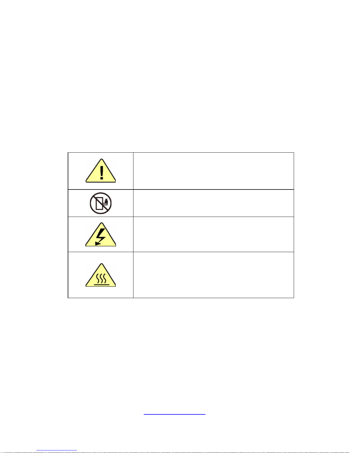
Symbols on Equipment
Caution. This symbol indicates a potential hazard.
The potential for injury exists if cautions are not
observed. Consult equipment documentation for
specific details.
Caution. Slide-mounted equipment is not to be
used as a shelf or a work space.
Warning. This symbol indicates the presence of
hazardous energy circuits or electric shock
hazards. Refer all servicing to qualified personnel.
Warning. This symbol indicates the presence of a
hot surface or hot component. If this surface is
contacted, the potential for injury exists.
To reduce risk of injury from a hot component,
allow the surface to cool before touching.
General Precautions
· Follow all caution and warning instructions marked on the equipment and
explained in the accompanying equipment documentation.
Machine Room Environment
· Make sure that the area in which you install the system is properly
ventilated and climate-controlled.
Page 9

9
http://www.tyan.com
· Ensure that the voltage and frequency of your power source match the
voltage and frequency inscribed on the electrical rating la bel of the
equipment.
· Do not install the system in or near a plenum, air duct, radiator, or heat
register.
· Never use the product in a wet location.
Equipment Chassis
· Do not block or cover the openings to the system.
· Never push objects of any kind through openings in the equipment.
Dangerous voltages might be present.
· Conductive foreign objects can produce a short circuit and cause fire,
electric shock, or damage to your equipment.
· Lift equipment using both hands and with your knees bent.
Equipment Racks
To avoid injury or damage to the equipment:
· Observe local occupational health and safety requirements and guidelines
for manual materials handling.
· Do not attempt to move a rack by yourself; a minimum of two people are
needed to move a rack.
· Do not attempt to move a fully loaded rack. Remove equipment from the
rack before moving it.
· Do not attempt to move a rack on an incline that is greater than 10 degrees
from the horizontal.
· Make sure the rack is properly secured to the floor or ceiling.
· Make sure the stabilizing feet are attached to the rack if it is a single-rack
installation.
· Make sure racks are coupled together if it is a multiple-rack installation.
· Make sure the rack is level and stable before installing an appliance in the
rack.
· Make sure the leveling jacks are extended to the floor.
Page 10

10
http://www.tyan.com
· Make sure the full weight of the rack rests on the leveling jacks.
· Always load the rack from the bottom up. Load the heaviest component in
the rack first.
· Make sure the rack is level and stable before pulling a component out of the
rack.
· Make sure only one component is extended at a time. A rack might become
unstable if more than one component is extended.
To avoid damage to the equipment:
· The rack width and depth must allow for proper serviceability and c able
management.
· Ensure that there is adequate airflow in the rack. Improper installation or
restricted airflow can damage the equipment.
· The rack cannot have solid or restricted airflow doors. You must use a
mesh door on the front and back of the rack or remove the doors to ensure
adequate air flow to the system.
· If you install the Model in a rack, do not place equipment on top of the unit.
It will cause restricted airflow and might cause damage to the equipment.
·
Make sure the product is properly matted with the rails. Products that are
improperly matted with the rails might be unstable.
·
Verify that the AC power supply branch circuit that provides power to the
rack is not overloaded. This will reduce the risk of personal injury, fire, or
damage to the equipment. The total rack load should not exceed 80 percent
of the branch circuit rating. Consult the electrical authority having jurisdiction
over your facility wiring and installation requirements.
Equipment Power Cords
· Use only the power cords and power supply units provided with your
system. The system might have one or more power cords.
· Plug the power cord into a grounded (earthed) electrical outlet that is easily
accessible at all times.
· In all European electrical environments, you must ground the Green/Yellow
tab on the power cord. If you do not ground the Green/Yellow tab, it can
cause an electrical shock due to high leakage currents.
·
Do not place objects on AC power cords or cables. Arrange them so that no
Page 11

11
http://www.tyan.com
one might accidentally step on or trip over them.
· Do not pull on a cord or cable. When unplugging from the electric al outlet,
grasp the cord by the plug.
· To reduce the risk of electrical shock, disconnect all power cords before
servicing the appliance.
Equipment Batteries
· The system battery contains lithium manganese dioxide. If the battery pack
is not handled properly, there is risk of fire and burns.
· Do not disassemble, crush, puncture, short external contacts, or dispose of
the battery in fire or water.
· Do not expose the battery to temperatures higher than 60°C (140°F).
· The system battery is not replaceable. If the battery is replaced by an
incorrect type, there is danger of explosion. Replace the ba ttery only with a
spare designated for your product.
· Do not attempt to recharge the battery.
· Dispose of used batteries according to the instructions of the manufacturer.
Do not dispose of batteries with the general household waste. To forward
them to recycling or proper disposal, use the public collection system or return
them to TYAN, your authorized TYAN partner, or their agents.
Equipment Modifications
· Do not make mechanical modifications to the system. TYAN is not
responsible for the regulatory compli ance of TYAN equipment that has been
modified.
Equipment Repairs and Servicing
· The installation of internal options and routine maintenance and service of
this product should be performed by individuals who are knowledgeable about
the procedures, precautions, and hazards associated with equipment
containing hazardous energy levels.
· Retain all screws or other fasteners when removing access cover(s). Upon
completion of accessing inside the product, refasten access cover with original
screws or fasteners.
Page 12

12
http://www.tyan.com
· Do not exceed the level of repair specified in the procedures in the product
documentation. Improper repairs can create a safety hazard.
· Allow the product to cool before removing covers and touching internal
components.
· Remove all watches, rings, or loose jewelry when working before removing
covers and touching internal components.
· Do not use conductive tools that could bridge live parts.
· Use gloves when you remove or replace system components; they can
become hot to the touch.
· If the product sustains damage requiring service, disconnect the product
from the AC electrical outlet and refer servicing to an authorized service
provider. Examples of damage requiring service includ e:
– The power cord, extension cord, or plug has been damaged.
– Liquid has been spilled on the product or an object has fallen into th e
product.
– The product has been exposed to rain or water.
– The product has been dropped or damaged.
– The product does not operate normally when you follow the operating
instructions.
Page 13

http://www.tyan.com
13
Table of Contents
Chapter 1: Overview....................................................................... 15
1.1 About the TYAN FT48T-B7105 .............................................. 15
1.2 Product Models ....................................................................... 16
1.3 Features .................................................................................. 17
1.4 Standard Parts List ................................................................. 25
1.4.1 Box Contents ................................................................... 25
1.5 About the Product ................................................................... 26
1.5.1 System Front View .......................................................... 26
1.5.2 System Rear View ........................................................... 29
1.5.3 System Top View ............................................................. 32
Chapter 2: Setting Up ..................................................................... 35
2.0.1 Before you Begin ............................................................. 35
2.0.2 Work Area ........................................................................ 35
2.0.3 Tools ................................................................................ 35
2.0.4 Precautions ...................................................................... 36
2.1 Installing Motherboard Components ...................................... 37
2.1.1 Removing the Chassis Cover .......................................... 37
2.1.2 Opening the Chassis Front Bezel .................................... 39
2.1.3 Installing the CPU and Heatsink ...................................... 40
2.1.4 Installing the Expansion Cards ........................................ 43
2.1.5 Installing the Memory ...................................................... 46
2.1.6 Installing Hard Drives ...................................................... 49
2.1.7 Installing the DVD-ROM .................................................. 51
2.2 Installing Foot Stands ............................................................. 54
2.3 Rack Mounting ........................................................................ 56
2.3.1 Installing the FT48T-B7105 in a Rack ............................. 56
Chapter 3: Replacing Pre-Installed Components ........................ 61
3.0.1 Introduction ...................................................................... 61
3.0.2 Disassembly Flowchart .................................................... 61
3.1 Removing the Cover ............................................................... 62
3.2 Replacing the System Fan ..................................................... 62
3.3 Replacing the Fan Board ........................................................ 63
3.3.1 Fan Board Features ......................................................... 65
3.3.2 Pin Definitions .................................................................. 66
3.4 Replacing the HDD Backplane Board .................................... 67
3.4.1 HDD BP Board Features ................................................. 68
3.4.2 Connector Pin Definitions ................................................ 69
3.5 Replacing the Front Panel Board ........................................... 70
3.5.1 Front Panel Board Features ............................................ 72
Page 14

http://www.tyan.com
14
3.5.2 Pin Definitions .................................................................. 73
3.6 Replacing the Power Supply .................................................. 74
3.7 Replacing the Power Distribution Board ................................. 75
3.7.1 Power Distribution Board Features ................................. 76
3.8 Removing the Motherboard .................................................... 77
Appendix I: How to recover UEFI BIOS ........................................ 79
Appendix II: How to install Power Wire Clip ................................ 81
Appendix III: Cable Connection Tables ........................................ 83
Appendix IV: Fan and Temp Sensors ........................................... 85
Appendix V: FRU Parts Table ........................................................ 89
Appendix VI: Technical Support ................................................... 91
Page 15

http://www.tyan.com
15
Chapter 1: Overview
1.1 About the TYAN FT48T-B7105
Congratulations on your purchase of the TYAN
®
FT48T-B7105, a highly optimized
Workstation barebone system. The FT48T-B7105 is design ed to support dual Intel
®
Xeon Scalable Processors and up to 384GB RDIMM / 768GB LRDIMM / 1536GB
RDIMM 3DS/LRDIMM 3DS DDR4 memory, providing a rich feature set and
incredible performance. Leveraging advanced technology from Intel
®
, the
FT48T-B7105 Workstation system is capable of offering scalable 32 and 64-bit
computing, high bandwidth memory design, and lightning-fast PCI-E bus
implementation. The FT48T-B710 5 not only empowers your company in no wadays
IT demand but also offers a smooth path for future application usage.
TYAN
®
also offers the FT48T-B7105 in a version that can support up to four
3.5”/2.5” hot-swap SSD/HDD. The FT48T-B7105 uses TYAN’s latest chassis
featuring a robust structure and a solid mechanical enclosure. All of this provides
FT48T-B7105 the power and flexibility to meet the needs of nowadays server
application.
Page 16
http://www.tyan.com
16
1.2 Product Models
The system board within the Tyan Barebone is defined by the following models:
B7105F48TV4HR-2T-N: Intel-based platform
B7105F48TV4HR-2T-G: Intel-based platform
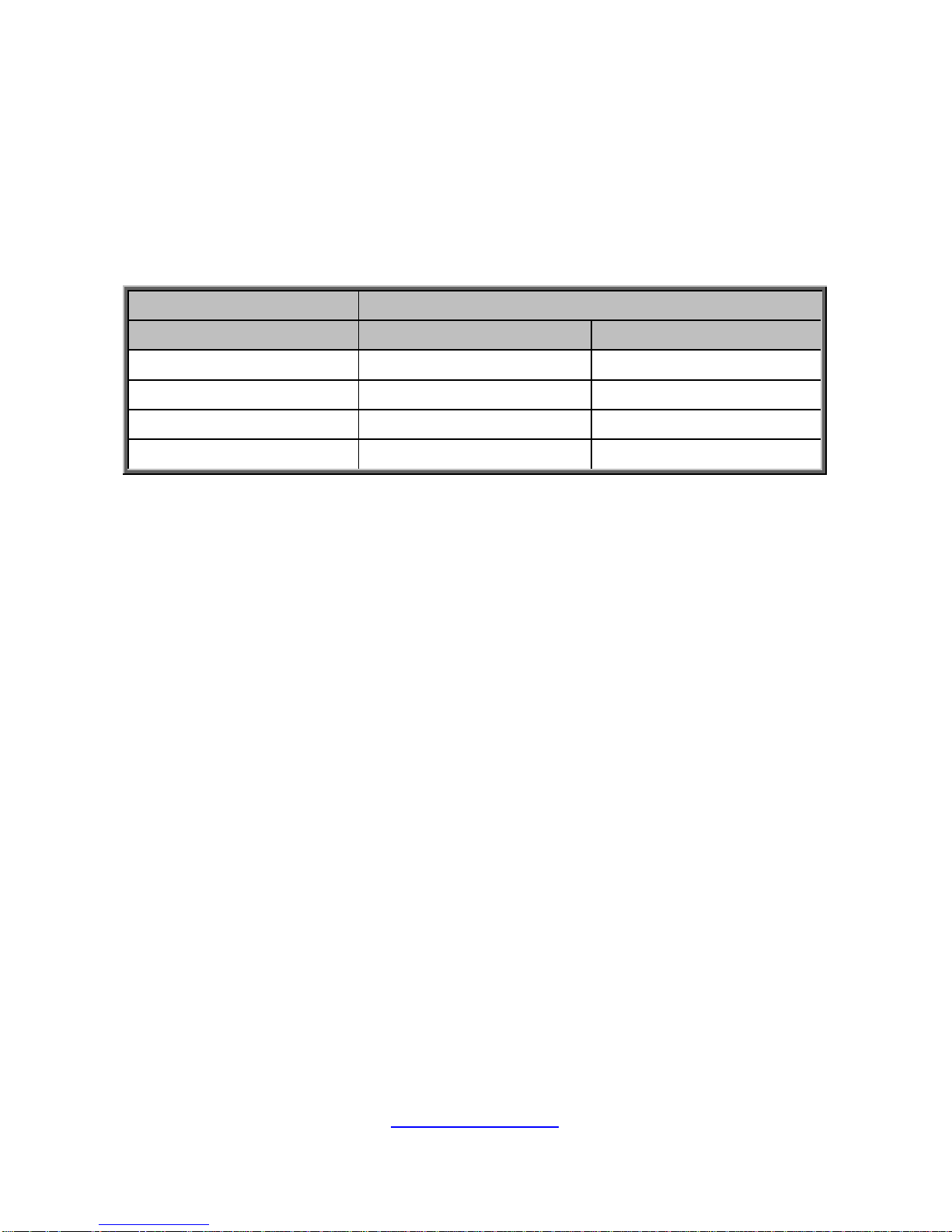
SKU Differences
Model Name FT48T-B7105
SKU Name B7105F48TV4HR-2T-N B7105F48TV4HR-2T-G
FAN 6 3
PCIe Air duct Yes No
CPU Air duct Yes Yes
Thermal solution on GPU Passive or Active Active
Page 17

http://www.tyan.com
17
1.3 Features
TYAN FT48T-B7105 (B7105F48TV4HR-2 T- N)
System
Net weight 34 kg (75 lbs)
Form Factor 4U Tower
Chassis Model FT48T
Dimension (D x W x
H)
27.5" x 16.8" x 6.9" (700 x 427 x
176mm)
Motherboard S7105AGM2NR-2T
Gross Weight 40 kg (88.5 lbs)
Front Panel
Buttons (1) RST, (1) ID, (1) PWR w/ LED
LEDs
(1) HDD, (2) LAN, (1) ID,
(1) System Event
I/O Ports (2) USB 3.0 port
External Drive Bay
Type / Q'ty
5.25" device bays, (3)
3.5"/2.5" Hot-Swap SSD/HDD, (4)
HDD Backplane
Support
SATA 6.0Gb/s
Supported HDD
Interface
(4) SATA 6Gb/s
System Cooling
Configuration
Redundancy Yes
FAN (5+1) hot-swap 12cm fans
Heat Sink (2) Passive CPU Heat sinks
Power Supply
Type RPSU
Input Range
100-127V~ / 220-240V~, 47-63Hz
System: 24A / 10A (max.)
Per Inlet: 12A / 10A
Output Watts
2000 Watts (100-127Vac input),
1968 Watts (220-240Vac input)
Efficiency 80 plus Platinum
Redundancy
1+1
NOTE:
1. When use 100V-127V AC
input, the system does not support
redundant PSU operation if the
total system load exceeds 12A
(1000 Watts).
2. When use 220V-240 AC
input, the system does not support
redundant PSU operation if the
total system load exceeds 10A
Page 18

http://www.tyan.com
18
(1968 Watts).
Processor
Socket Type / Q'ty LGA3647/ (2)
System Bus
Up to 10.4/9.6 GT/s with Intel
UltraPath Interconnect (UPI)
support
Supported CPU
Series
Intel Xeon Scalable Processor
Thermal Design
Power (TDP) wattage
Max up to 205W
Chipset
PCH Intel C621
Memory
Supported DIMM
Qty
(6)+(6) DIMM slots
DIMM Type / Speed
DDR4 RDIMM/RDIMM
3DS/LRDIMM/LRDIMM 3DS 2666
Capacity
Up to 384GB RDIMM/ 768GB
LRDIMM/ 1,536GB RDIMM
3DS/LRDIMM 3DS *Follow latest
Intel DDR4 Memory POR
Memory channel 6 Channels per CPU
Memory voltage 1.2V
Expansion Slots
PCI-E
(1) PCI-E Gen3 x16 slot, max 25
Watts
(5) PCI-E Gen3 x16 slots, max 75
Watts
NOTE: Please note the thermal
design power (TDP) of GPU must
be equal or less than 250W or OCP
(over current protect) will occur.
LAN
Port Q'ty
(2) 10GbE ports,
(1) GbE port dedicated for IPMI
Controller Intel X550-AT2
PHY Realtek RTL8211E
Storage
SATA
Connector (2) SATA
Controller Intel C621
Speed 6.0 Gb/s
RAID
RAID 0/1/10/5 (Intel
RSTe)
sSATA
Connector
(2) Mini-SAS HD
(8-ports)
Controller Intel C621
Page 19

http://www.tyan.com
19
Speed 6.0 Gb/s
RAID
RAID 0/1/10/5 (Intel
RSTe)
NVMe Connector (M.2)
(2) 22110/2280 (by
PCI-E & SATA interface)
Graphic
Connector type D-Sub 15-pin
Resolution Up to 1920x1200
Chipset Aspeed AST2500
I/O Ports
USB
(2) USB3.0 ports (at rear),
(2) USB3.0 ports (at front)
VGA (1) D-Sub 15-pin port
Audio 2.1
RJ-45
(2) 10GbE ports,
(1) GbE dedicated for IPMI
Others ID LED
TPM (Optional)
TPM Support
Please refer to our TPM supported
list.
System Monitoring
Chipset Aspeed AST2500
Temperature
Monitors temperature for CPU &
memory & system environment
Voltage
Monitors voltage for CPU,
memory, chipset & power supply
LED
Over temperature warning
indicator, Fan & PSU fail LED
indicator
Others Watchdog timer support
Server Management
AST2500 iKVM
Feature
IPMI 2.0 compliant baseboard
management controller (BMC),
Supports storage over IP and
remote platform-flash, USB 2.0
virtual hub
AST2500 IPMI
Feature
24-bit high quality video
compression, 10/100/1000 Mb/s
MAC interface
Onboard Chipset Onboard Aspeed AST2500
BIOS
Brand / ROM size AMI, 32MB
Feature
Hardware Monitor, SMBIOS
3.0/PnP/Wake on LAN, Boot from
USB device/PXE via LAN/Storage,
User Configurable FAN PWM Duty
Page 20

http://www.tyan.com
20
Cycle, Console Redirection, ACPI
sleeping states S4,S5, ACPI 6.1
Operating System
OS supported list
Please refer to our AVL support
lists.
Regulation
CB/LVD Yes
RCM Class A
FCC (SDoC) Class A
CE (DoC) Class A
VCCI Class A
Operating Environment
Operating Temp. 10° C ~ 35° C (50° F~ 95° F)
Non-operating Temp. - 40° C ~ 70° C (-40° F ~ 158° F)
In/Non-operating
Humidity
90%, non-condensing at 35° C
RoHS
RoHS 6/6 Compliant Yes
Package Contains
Manual (1) Quick Installation Guide
Installation CD (1) TYAN Device Driver CD
Barebone
(1) FT48T-B7105 w/NV
Tesla-aware FW Barebone
Others
For rackmount solution, please
contact Tyan sales
TYAN FT48T-B7105 (B7105F48TV4HR-2 T- G)
System
Net weight 34 kg (75 lbs)
Form Factor 4U Tower
Chassis Model FT48T
Dimension (D x W x
H)
27.5" x 16.8" x 6.9" (700 x 427 x
176mm)
Motherboard S7105AGM2NR-2T
Gross Weight 40 kg (88.5 lbs)
Front Panel
Buttons (1) RST, (1) ID, (1) PWR w/ LED
LEDs
(1) HDD, (2) LAN, (1) ID,
(1) System Event
I/O Ports (2) USB 3.0 port
External Drive Bay
Type / Q'ty
5.25" device bays, (3)
3.5"/2.5" Hot-Swap SSD/HDD, (4)
Page 21

http://www.tyan.com
21
HDD Backplane
Support
SATA 6.0Gb/s
Supported HDD
Interface
(4) SATA 6Gb/s
System Cooling
Configuration
Redundancy Yes
FAN (3) hot-swap 12cm fans
Heat Sink (2) Passive CPU Heat sinks
Power Supply
Type RPSU
Input Range
100-127V~ / 220-240V~, 47-63Hz
System: 24A / 10A (max.)
Per Inlet: 12A / 10A
Output Watts
2000 Watts (100-127Vac input),
1968 Watts (220-240Vac input)
Efficiency 80 plus Platinum
Redundancy
1+1
NOTE:
1. When use 100V-127V AC
input, the system does not support
redundant PSU operation if the
total system load exceeds 12A
(1000 Watts).
2. When use 220V-240 AC
input, the system does not support
redundant PSU operation if the
total system load exceeds 10A
(1968 Watts).
Processor
Socket Type / Q'ty LGA3647/ (2)
System Bus
Up to 10.4/9.6 GT/s with Intel
UltraPath Interconnect (UPI)
support
Supported CPU
Series
Intel Xeon Scalable Processor
Thermal Design
Power (TDP) wattage
Max up to 205W
Chipset
PCH Intel C621
Memory
Supported DIMM
Qty
(6)+(6) DIMM slots
DIMM Type / Speed
DDR4 RDIMM/RDIMM
3DS/LRDIMM/LRDIMM 3DS 2666
Capacity
Up to 384GB RDIMM/ 768GB
LRDIMM/ 1,536GB RDIMM
3DS/LRDIMM 3DS *Follow latest
Page 22

http://www.tyan.com
22
Intel DDR4 Memory POR
Memory channel 6 Channels per CPU
Memory voltage 1.2V
Expansion Slots
PCI-E
(1) PCI-E Gen3 x16 slot, max 25
Watts
(5) PCI-E Gen3 x16 slots, max 75
Watts
NOTE: Please note the thermal
design power (TDP) of GPU must
be equal or less than 250W or OCP
(over current protect) will occur.
LAN
Port Q'ty
(2) 10GbE ports,
(1) GbE port dedicated for IPMI
Controller Intel X550-AT2
PHY Realtek RTL8211E
Storage
SATA
Connector (2) SATA
Controller Intel C621
Speed 6.0 Gb/s
RAID
RAID 0/1/10/5 (Intel
RSTe)
sSATA
Connector
(2) Mini-SAS HD
(8-ports)
Controller Intel C621
Speed 6.0 Gb/s
RAID
RAID 0/1/10/5 (Intel
RSTe)
NVMe Connector (M.2)
(2) 22110/2280 (by
PCI-E & SATA interface)
Graphic
Connector type D-Sub 15-pin
Resolution Up to 1920x1200
Chipset Aspeed AST2500
I/O Ports
USB
(2) USB3.0 ports (at rear),
(2) USB3.0 ports (at front)
VGA (1) D-Sub 15-pin port
Audio 2.1
RJ-45
(2) 10GbE ports,
(1) GbE dedicated for IPMI
Others ID LED
Page 23

http://www.tyan.com
23
TPM (Optional)
TPM Support
Please refer to our TPM supported
list.
System Monitoring
Chipset Aspeed AST2500
Temperature
Monitors temperature for CPU &
memory & system environment
Voltage
Monitors voltage for CPU,
memory, chipset & power supply
LED
Over temperature warning
indicator, Fan & PSU fail LED
indicator
Others Watchdog timer support
Server Management
AST2500 iKVM
Feature
IPMI 2.0 compliant baseboard
management controller (BMC),
Supports storage over IP and
remote platform-flash, USB 2.0
virtual hub
AST2500 IPMI
Feature
24-bit high quality video
compression, 10/100/1000 Mb/s
MAC interface
Onboard Chipset Onboard Aspeed AST2500
BIOS
Brand / ROM size AMI, 32MB
Feature
Hardware Monitor, SMBIOS
3.0/PnP/Wake on LAN, Boot from
USB device/PXE via LAN/Storage,
User Configurable FAN PWM Duty
Cycle, Console Redirection, ACPI
sleeping states S4,S5, ACPI 6.1
Operating System
OS supported list
Please refer to our AVL support
lists.
Regulation
CB/LVD Yes
RCM Class A
FCC (SDoC) Class A
CE (DoC) Class A
VCCI Class A
Operating Environment
Operating Temp. 10° C ~ 35° C (50° F~ 95° F)
Non-operating Temp. - 40° C ~ 70° C (-40° F ~ 158° F)
In/Non-operating
Humidity
90%, non-condensing at 35° C
RoHS
RoHS 6/6 Compliant Yes
Page 24

http://www.tyan.com
24
Package Contains
Manual (1) Quick Installation Guide
Installation CD (1) TYAN Device Driver CD
Barebone (1) FT48T-B7105 Barebone
Others
For rackmount solution, please
contact Tyan sales
NOTE:
1. The specifications are subject to change without prior notice.
2. Please visit our Web site for the latest information.
Page 25

http://www.tyan.com
25
1.4 Standard Parts List
This section describes FT48T-B7105 package co ntents and accessories. Open the
box carefully and ensure that all components are present and undamaged. The
product should arrive packaged as illustrated below.
1.4.1 Box Contents
FT48T-B7105 Box Content
4U barebone, (4) hot swap HDD bays
(1+1), 2000W power supply unit --- B7105F48TV4HR-2T-N /
B7105F48TV4HR-2T-G
S7105AGM2NR-2T system board (pre-installed)
M1019-FPB (pre-installed)
(3) system fans, (6 system fans for B7105F48TV4HR-2T-N)
M1809F77A-FB (pre-installed)
M1622F48T-D-PDB (pre-installed)
M1237F48-BP6-4-7055 HDD BP
FT48T-B7105 Accessories
CPU Clip*2
CPU Heatsink *2
Quick Installation Guide *1
Addendum for China Use Only *1
Driver’s and Utility CD *1
Foot Stand*4 & Screw *4
CD_ROM_Rail *3
CD_ROM_Rail Screw Kit *1
AC Power Cord (US) *2
AC Power Cord (EU) *2
GPU Card Holder Kit *5
PCIe Air Duct Kit *1 (only for B7105F48TV4HR-2T-N)
8-pin CPU Power Cable *5 (only for B7105F48TV4HR-2T -N)
6-Pin +8-pin PCIe Power Cable *5
SATA Internal Cable *2
SATA Power Cable *2
Screw Pack for M.2 *2
Screw Pack for HDD *2
Sliding Rail *1 (Optional)
Page 26
http://www.tyan.com
26
1.5 About the Product
The following views show you the product.
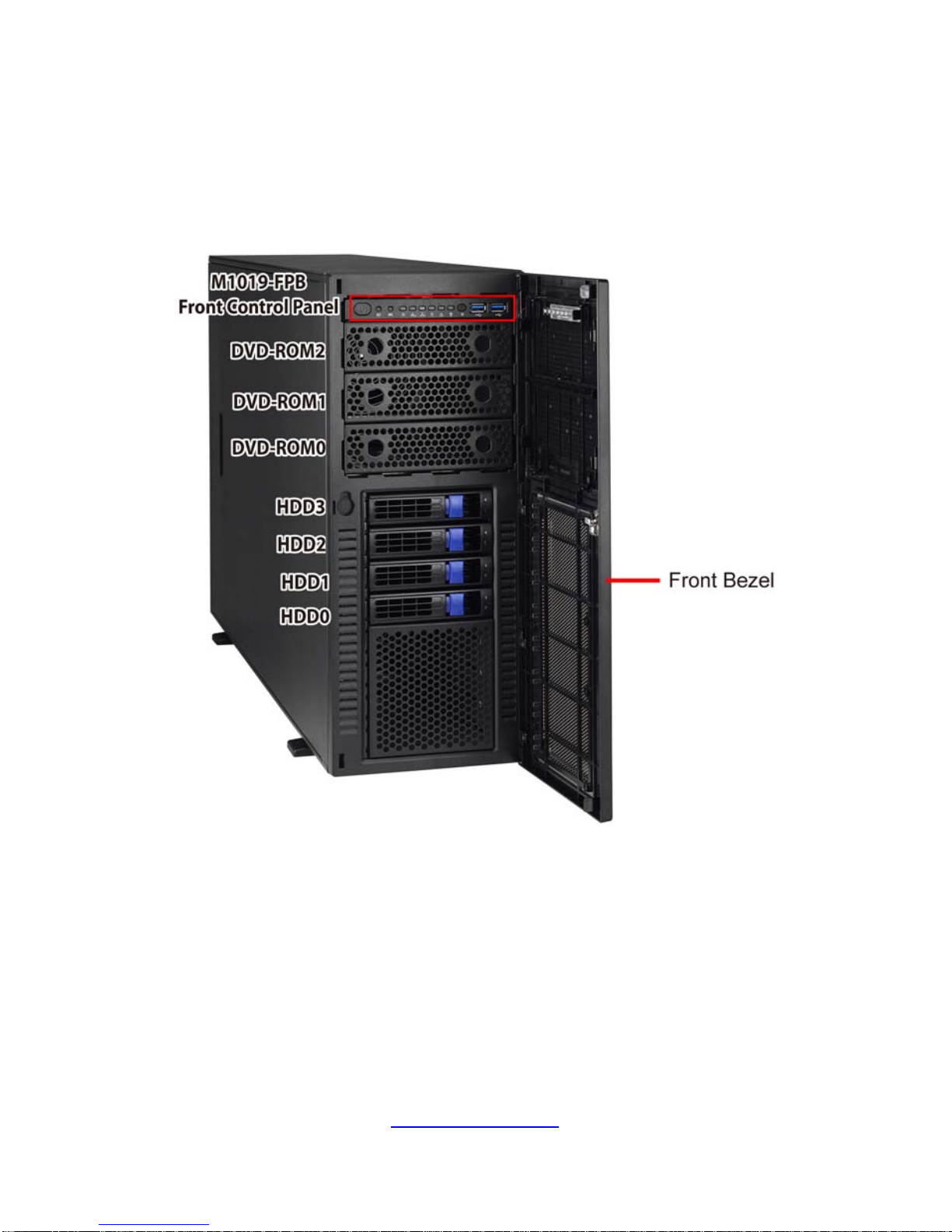
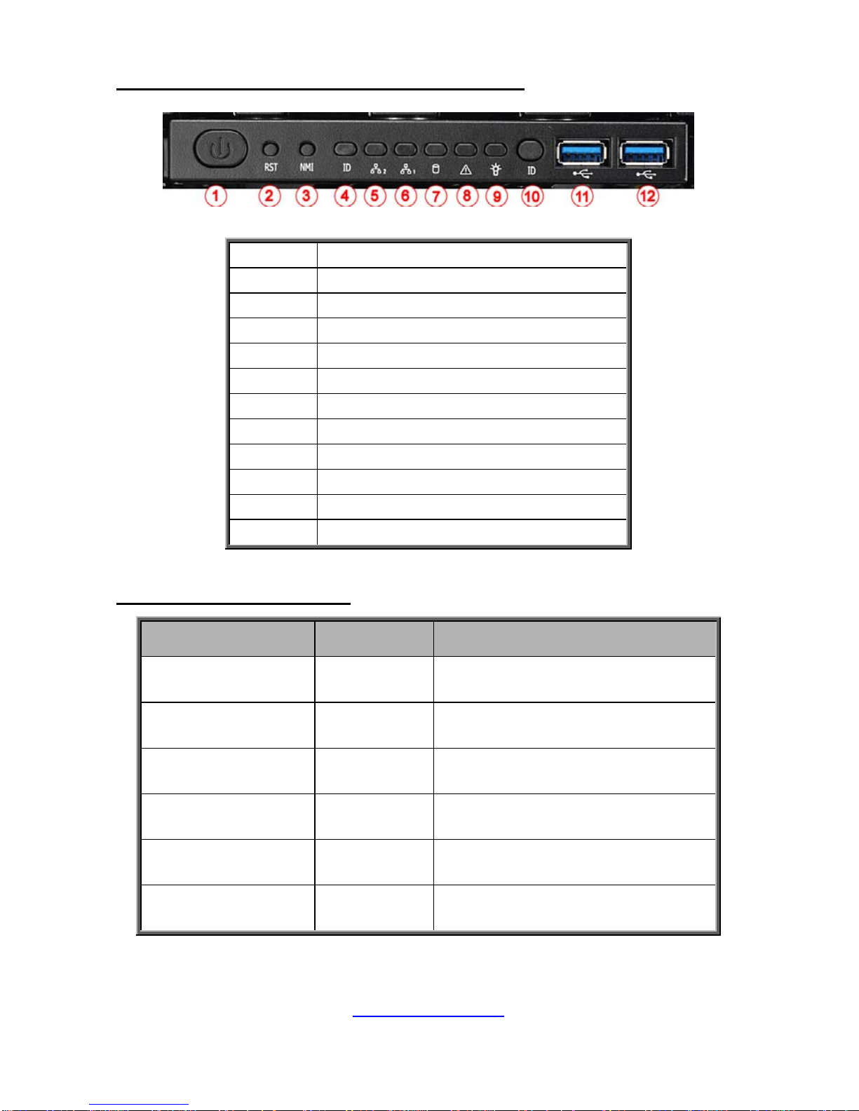
1.5.1 System Front View
Page 27
http://www.tyan.com
27
Front Control Panel (M1019-FPB pre-installed)
1 Power Button
2 Reset Button
3 NMI Button
4 ID LED
5 LAN2 LED
6 LAN1 LED
7 HDD LED
8 Warning LED
9 Power LED
10 ID Button
11 USB3.0 Port 2
12 USB3.0 Port 1
M1019-FPB LED Definition
LED Color Behavior
#4 ID LED Blue
Located / Solid On
Normal / Normal
#5 LAN2 LED Green
Access / Blinking
Linking / Solid On
#6 LAN1 LED Green
Access / Blinking
Linking / Solid On
#7 HDD LED Amber
Ready / Off
Access / Blinking
#8 Warning LED Amber
System Normal / Off
System Warning / Solid On
#9 Power LED Green
System Power On / Solid On
System Power Off / Off
Page 28
http://www.tyan.com
28
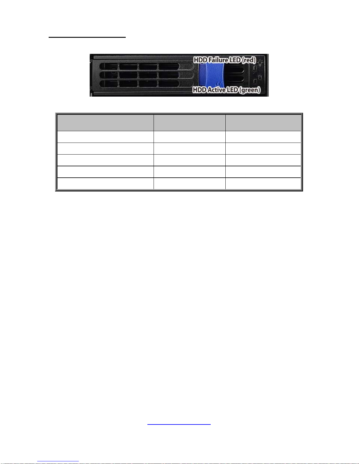
HDD LED Definitions
Drive State
A
ctive LED
(Green)
Failure LED
(Red)
Drive present, no activity Green Solid On Off
Drive present, with activity Green Blinking Off
Drive Failed Don’t care Red Solid On
Drive dentify Don’t care Red Blinking @1 Hz
Drive Rebuild Don’t care Red Blinking @4 Hz
Page 29

http://www.tyan.com
29
1.5.2 System Rear View
1 PSU0 8 IPMI Port
2 PSU1 9 LAN2
3 MIC 10 LAN1
4 LINE-OUT 11 VGA Port
5 LINE-IN 12 ID LED
6 USB3.0 Port2 13 Expansion Slots
7 USB3.0 Port1
Page 30

http://www.tyan.com
30
10Gbps LAN Port LAN Indication
10Gbps LAN Link/Activity LED Scheme
Left LED
(Link/Activity)
LED Color: Green
Right LED
(Speed)
LED Color: Yellow
No Link OFF OFF
100 Mbps
Link Green Solid On Green Solid On
Active Green Blinking Green Solid On
1000 Mbps
(1Gbps)
Link Green Solid On Yellow Solid On
Active Green Blinking Yellow Solid On
10 Gbps
Link Yellow Solid On Yellow Solid On
Active Yellow Blinking Yellow Solid On
1Gbps LAN Port LAN Indication
1Gbps LAN Link/Activity LED Scheme
Left LED
(Link/Activity)
LED Color: Green
Right LED
(Speed)
LED Color: Amber
No Link OFF OFF
10 Mbps
Link Green Solid On OFF
Active Green Blinking OFF
100 Mbps
Link Green Solid On Green Solid On
Active Green Blinking Green Solid On
1000 Mbps
(1Gbps)
Link Green Solid On Amber Solid On
Active Green Blinking Amber Solid On
NOTE: “Left” and “Right” are viewed from the rear panel.
Page 31

http://www.tyan.com
31
Power LED Definitions
Bicolor
Power Supply condition Green LED Amber LED
No AC power to all power supplies OFF OFF
Power supply critical event causing a shutdown;
failure, OCP, OVP, Fan Fail, OTP, UVP
OFF Amber Solid ON
Power supply warning events where the power
supply continues to opeate; high temp (inlet
temperature>51 deg (PMBus reading), or hot spot
temperature >95 deg (PMBus reading), high power,
high current, slow fan (Fan warning +/- 20% RPM)
OFF Amber Blinking
@1Hz
AC present Only 12VSB on (PS off) or PS in Smart
Redundant state
Green Blinking
@1Hz
OFF
Output ON and OK Green Solid ON OFF
AC cord unplugged or AC power lost with a second
power supply in parallel still with AC input power
OFF Amber Solid ON
Page 32

http://www.tyan.com
32
1.5.3 System Top View
B7105F48TV4HR-2T-N
1 (4) HDD tra ys (M1237F48-BP6-4 HDD Backplane Board pre-installed)
2 (3) DVD-ROM tra ys (M1019-F PB Front Panel Board pre-installed)
3 FAN6
4 FAN5
5 FAN4
6 FAN3
7 FAN2
8 FAN1
NOTE: M1809F77A-FB Fan Board is pre-installed.
9 Air Duct
10 Power Supply
11 M1622F48T-D-PDB (pre-installed)
Page 33

http://www.tyan.com
33
B7105F48TV4HR-2T-G
1 (4) HDD tra ys (M1237F48-BP6-4 HDD Backplane Board pre-installed)
2 (3) DVD-ROM tra ys (M1019-F PB Front Panel Board pre-installed)
3 FAN3
4 FAN2
5 FAN1
NOTE: M1809F77A-FB Fan Board is pre-installed.
6 Air Duct
7 Power Supply
8 M1622F48T-D-PDB (pre-installed)
Page 34

http://www.tyan.com
34
NOTE
Page 35

http://www.tyan.com
35
Chapter 2: Setting Up
2.0.1 Before you Begin
This chapter explains how to install the CPUs, CPU heatsinks, memory
modules, and SSD/HDD. Instructions on inserting add on
cards are also given.
2.0.2 Work Area
Make sure you have a stable, clean working environment. Dust and dirt
can get into components and cause malfunctions. Use containers to
keep small components separated. Putting all small components in
separate containers prevents them from becoming lost. Adequate
lighting and proper tools can prevent you from accidentally damaging
the internal components.
2.0.3 Tools
The following procedures require only a few tools, including the
following:
A cross head (Phillips) screwdriver
A grounding strap or an anti-static pad
A T30 Security Torx screwdriver
Most of the electrical and mechanical connections can be disconn ected
with your hands. It is recommended that you do not use pliers to remove
connectors as it may damage the soft metal or plastic parts of the
connectors.
Caution!
1. To avoid damaging the motherboard and as sociated
components, do not use torque force greater than 5~7
kgf/cm (4.35 ~ 6.09 lb/in) on each mounting screw
for motherboard installation.
2. Do not apply power to the board if it has been
damaged.
Page 36

http://www.tyan.com
36
2.0.4 Precautions
Components and electronic circuit boards can be damaged by
discharges of static electricity. Working on a s ystem that is connected to
a power supply can be extremely dangerous. Follow the guidelines below
to avoid damage to FT48T-B7105 or injury to yourself.
Ground yourself properly before removing the top cover of the
system. Unplug the power from the power supply and then touch a
safely grounded object to release static charge (i.e. power supply
case). If available, wear a grounded wrist strap. Alternatively,
discharge any static electricity by touching the bar e metal chassis
of the unit case, or the bare metal body of any other grounded
appliance.
Avoid touching motherboard components, IC chips, connectors,
memory modules, and leads.
The motherboard is pre-installed in the system. When removing
the motherboard, always place it on a groun ded anti-static surface
until you are ready to reinstall it.
Hold electronic circuit boards by the edges only. Do not touch the
components on the board unless it is necessary to do so. Do not
flex or stress circuit boards.
Leave all components inside the static-proof packaging that they
ship with until they are ready for installation.
After replacing optional devices, make sure all screws, springs, or
other small parts are in place and are not left loose inside the case.
Metallic parts or metal flakes can cause electrical shorts.
CAUTION: Please note that the following illustrations may not look
exactly like the rackmount server you purchased. Therefore, the
illustrations should be held for your reference only.
Page 37

http://www.tyan.com
37
2.1 Installing Motherboard Components
This section describes how to install components on to the motherboard, including
CPUs, memory modules, SSD/HDD and PCI-E cards.
2.1.1 Removing the Chassis Cover
Follow these instructions to remove the FT48T-B7105 chassis cover.
1. Loosen one screw and two thumb screws to slide the top cover off.
Page 38

http://www.tyan.com
38
2. Unscrew to remove the CPU air duct from the chassis.
Page 39

http://www.tyan.com
39
2.1.2 Opening the Chassis Front Bezel
Follow these instructions to open the chassis front bezel.
1. Insert the front bezel key (packed in a bag in the accessory box) and rotate the
key 90 degrees counterclockwise to unlock the front bezel.
2. Open the front bezel.
Page 40

http://www.tyan.com
40
2.1.3 Installing the CPU and Heatsink
Follow the steps below on installing CPUs and CPU heatsinks.
1. Align and install the processor on the carrier.
2. Carefu lly flip the heatsink. Then install the carrier assembly on the bottom of
the heatsink and make sure the guide pin is located in the correct direction.
Page 41

http://www.tyan.com
41
3. Always start with CPU0 first. Remove the CPU Socket protection cap. Locate
the CPU socket’s guide pin.
NOTE: A new heatsink comes with pre-applied thermal grease.
Once the heatsink has been removed from the processor, you need to clean the
processor and heatsink using an alcohol solvent. Then apply new thermal grease
before reinstalling the heatsink.
4. Carefully flip the heatsink. Align the heatsink with the CPU socket by the guide
pin and make sure the guide pin is located in the correct direction. T hen place the
heatsink onto the top of the CPU socket.
Page 42

http://www.tyan.com
42
5. To secure the heatsink, use a T30 Security Torx to tighten the screws in a
sequential order (1234).
NOTE: When disassembling the heatsink, loosen the screws in reverse order
(4321).
6. Repeat the procedures described earlier to install the second processor and
heatsink.
7. Place the CPU air duct back and screw it to the chassis.
Page 43

http://www.tyan.com
43
2.1.4 Installing the Expansion Cards
Follow the instructions to install the expansion cards.
1. Locate the PCI-E Gen.3 slots on the motherboard. Unscrew to take out the
dummy brackets.
2. Screw the GPU bracket to the GPU card.
Page 44

http://www.tyan.com
44
3. Locate the guide pins of the GPU air duct. Place the GPU air duct on the
chassis wall.
4. Insert the GPU card into the PCIE Gen. 3 slot and screw the GPU card to the
chassis.
Page 45

http://www.tyan.com
45
5. Connect the GPU Power cable.
6. Replace the GPU air duct and screw it to the Mid-bar.
Page 46

http://www.tyan.com
46
2.1.5 Installing the Memory
Follow these instructions to install the memory modules onto the motherboard.
1. Locate the memory slots on the motherboard.
2. Press the memory slot locking levers in the direction of the arrows as shown in
the following illustration.
3. Alig n the memor y module with the sl ot. When inserted properly, the memory
slot locking levers lock automatically onto the indentations at the ends of the
module. Follow the recommended memory population table to install the
other memory modules.
Page 47

http://www.tyan.com
47
DIMM Location
Page 48

http://www.tyan.com
48
Recommended Memory Population Table (Single CPU)
Single CPU Installed (CPU0 only)
Quantity of
memory installed
1 2 3 4 5 6
P0_MCO_DIM_CH_A0 √ √ √ √ √ √
P0_MCO_DIM_CH_B0 √ √ √ √ √
P0_MCO_DIM_CH_C0 √ √ √ √
P0_MC1_DIM_CH_D0 √ √ √
P0_MC1_DIM_CH_E0 √ √
P0_MC1_DIM_CH_F0 √
NOTE:
1. √ indicates a populated DIMM slot.
2. Use paired memory installation for max performance.
3. Populate the same DIMM type in each channel, specifically
- Use the same DIMM size
- Use the same # of ranks per DIMM
Recommended Memory Population Table (Dual CPU)
Dual CPU installed (CPU0 and CPU1)
Quantity of
memory installed
2 4 6 8 10 12
P0_MCO_DIM_CH_A0 √ √ √ √ √ √
P0_MCO_DIM_CH_B0 √ √ √ √ √ √
P0_MCO_DIM_CH_C0 √ √ √ √ √
P0_MC1_DIM_CH_D0 √ √ √ √ √
P0_MC1_DIM_CH_E0 √ √ √ √
P0_MC1_DIM_CH_F0 √ √ √ √
P1_MCO_DIM_CH_A0 √ √ √
P1_MCO_DIM_CH_B0 √ √ √
P1_MCO_DIM_CH_C0 √ √
P1_MC1_DIM_CH_D0 √ √
P1_MC1_DIM_CH_E0 √
P1_MC1_DIM_CH_F0 √
Page 49

http://www.tyan.com
49
2.1.6 Installing Hard Drives
The FT48T-B7105 can support up to four (4) 3.5”/2.5” SSD/HDD. Follow these
instructions to install a hard drive.
Warning!!! Always install the hard disk drive to the chassis after the chassis is
secured on the rack.
1. Press the locking lever latch and pull the locking lever open.
2. Slide the HDD tray out.
3. Place a 3.5"/2.5” SSD/HDD into the HDD tray.
3.5” HDD
Page 50

http://www.tyan.com
50
2.5” SSD/HDD
4. Turn over the HDD unit and secure the SSD/HDD using 4 HDD screws.
5. Reins ert the HDD tray into the chassis and press the locking lever to secure
the tray. Close the front bezel.
Page 51

http://www.tyan.com
51
2.1.7 Installing the DVD-ROM
Follow these instructions to install the DVD-ROM.
1. Take out the DVD-ROM Kit.
2. Assemble the DVD Rail-L and Rail-R to the DVD device and secure with 8
screws.
3. Open the front bezel, and select the device tray where to insert the
DVD-ROM.
Page 52

http://www.tyan.com
52
4. Unscrew to remove the selected device tray as shown below.
5. Install the DVD-ROM into the chassis.
Page 53

http://www.tyan.com
53
6. Connect the SATA cable to the motherboard and route the cable along the
side of the chassis.
7. Connect the DVD-ROM PWR cable to the Power Distribution Board.
8. Connect the SATA cable and PWR cable to the DVD-ROM device.
Page 54

http://www.tyan.com
54
2.2 Installing Foot Stands
Follow these instructions to install the footsands.
1. Peel off the mylars.
2. Take out the Footstand Kit.
Page 55

http://www.tyan.com
55
3. Screw the footstands to the chassis (both front and rear).
Page 56

http://www.tyan.com
56
2.3 Rack Mounting
After installing the necessary components, the TYAN FT48T-B7105 can be mounted
in a rack using the supplied rack mounting kit
Rack Mount Kit
Rail with Bracket x 2
Mounting Ears x 2
Screw Sack x 1
Screw Sack
A: Nut for M6 screw --- 10 pcs
B: M6--10 pcs
2.3.1 Installing the FT48T-B7105 in a Rack
Follow these instructions to mount the TYAN FT48T-B7105 into an industry standard
19” rack.
NOTE: Before mounting the TYAN FT48T-B7105 in a rack, ensure that a ll internal
components have been installed and that the unit has been fully tested. However, to
make the installation easier, we suggest that you remove all HDD trays before you
insert the chassis to the rack.
Installing the Inner Rails to the Unit
1. Unscrew to remove the side cover.
A B
Page 57

http://www.tyan.com
57
2. Screw the mounting ears to the FT48T-B7105 as shown using six M4-L5
screws (black).
Left Right
3. Press the latch to draw out the inner rails from each rail assembly.
4. Install the inner sliding rail to each side of the server using five M4-L5 screws.
Page 58

http://www.tyan.com
58
Installing the Outer Rails to the Unit
1. Adjust the outer rails to fit the length of the rack. The sliding brackets have
long slits to allow them to be fixed to the other part of the rails in various
positions.
2. Secure the outer rails to the rack using four M6 (2 front, 2 rear) screws (B) and
five nut (3 front, 2 rear) (A) for each side. Secure the mounting brackets fr om
outside, not inside of the rack.
Page 59

http://www.tyan.com
59
Rack Mounting the Server
1. Lift the unit and then insert the inner slide rails into the middle rails.
2. Push the whole system in.
Page 60

http://www.tyan.com
60
3. Secure the mounting ears to the rack using two M6 screws (B).
4. Push the latch on both sides of the chassis simultaneously to pull the s ystem
out.
Page 61

http://www.tyan.com
61
Chapter 3: Replacing Pre-Installed Components
3.0.1 Introduction
This chapter explains how to replace the pre-installed components, including the
S7105 Motherboard, M1019-FPB F ront Panel Board, M1237F48-BP6-4 SATA/SAS
HDD Backplane Board, M1809F77A-FB Fan Board, M1622F48T-D-PDB Power
Distribution Board, System Fan and Power Supply Unit etc.
3.0.2 Disassembly Flowchart
The following flowchart outlines the disassembly procedures.
Page 62

http://www.tyan.com
62
3.1 Removing the Cover
Before replacing any parts you must remove the chassis cover. Follow Section 2.1.1
Removing the Chassis Cover (page 37) to remove the cover of the FT48T-B7105.
3.2 Replacing the System Fan
Follow these instructions to replace the system fan.
1. Take out the failed fans.
2. Prepare new fans and insert them into the fan cage.
Page 63

http://www.tyan.com
63
3.3 Replacing the Fan Board
Follow these instructions to replace the fan board.
1. Unscrew the fan cage and remove all system fans and from the fan cage.
2. Take out the fan cage.
3. Disconnect all cables from the fan board.
Page 64

http://www.tyan.com
64
4. Unscrew the fan board to replace with a new one.
5. Assemble the fan cage and system fans back into the c hassis following
the steps described earlier in reverse.
Page 65

http://www.tyan.com
65
3.3.1 Fan Board Features
M1809F77A-FB Fan Board
Form Factor
W81.4 x L312.28 (mm), 4-layer PCB
Specifications
(4) Big 4P Power Connector (J7/J9/J10/J11)
(6) 2x2-pin FAN Connector (J1/J2/J3/J4/J5/J6)
(1) 2x10-pin TYAN Barebone FAN Connector (J8)
FAN Sequence
Page 66

66
http://www.tyan.com
3.3.2 Pin Definitions
J1/J2/J3/J4/J5/J6: 2x2-pin Power Connector
Definition Pin Pin Definition
GND 1 2 +12V
TACH 3 4 PWM
J8: 2×10-Pin System Fan Connector for Motherboard
Definition Pin Pin Definition
Tachometer Input1 1 2 Tachometer Input6
Tachometer Input2 3 4 Tachometer Input7
Tachometer Input3 5 6 Tachometer Input8
Tachometer Input4 7 8 Tachometer Input9
Tachometer Input5 9 10 Tachometer Input10
GND 11 12 KEY
PWM Output2 13 14 PWM Output1
Tachometer Input11 15 16 SMB Data
Tachometer Input12 17 18 SMB Clock
3.3V Standby 19 20 PWM Output3
J7/J9/J10/J11: 1×4-Pin ATX Power Connector for Fan
Definition Pin Pin Definition
+12V 1 2 GND
GND 3 4 NC
Page 67

67
http://www.tyan.com
3.4 Replacing the HDD Backplane Board
Follow these instructions to replace the M1237F48-BP6-4 SATA/SAS HDD
Backplane Board.
1. Refer to Section 3.3 Replacing the Fan Board on how to remove the Fan
Cage and Fan Board.
2. Disconnect all cables attached to the HDD BP Board and unscrew to take it
out.
3. Prepare a new HDD BP Board and reinstall it into the chassis following the
steps in reverse.
Page 68

68
http://www.tyan.com
3.4.1 HDD BP Board Features
Here shows the M1237F48-BP6-4 HDD Backplane Board in details.
Front view:
Rear view:
M1237F48-BP6-4 HDD Backplane Board
Specifications
(2) Big 4-pin Power Connectors (J35/J36)
(4) SATA 7-pin Connectors (J15/J16/J17/J13)
(4) port 3.5” SAS/SATA 12Gb/s & hot-swap support
(J1/J2/J4/J5)
(1) 2x5-pin SGPIO Connector to MB (J18)
(1) 2x5-pin CPLD JTAG Connector (J6)
Page 69

69
http://www.tyan.com
3.4.2 Connector Pin Definitions
J6: Burning FW Header
Definition Pin Pin Definition
CPLD_JTAG_TCK 1 2 GND
CPLD_JTAG_TDO 3 4 VDD_3P3_RUN
CPLD_JTAG_TMS 5 6 NC
NC 7 8 KEY Pin
CPLD_JTAG_TDI 9 10 GND
J18: SGPIO Header
Definition Pin Pin Definition
FPIO_SCL 1 2 SDATAIN
FPIO_SDA 3 4 SDATAOUT
GND 5 6 SAS_SIO_END_A
KEY Pin 7 8 SAS_SIO_CLK_A
NC 9 10 HD_ERR_LED
J35/J36: Big 4 pin Power Connector
Definition Pin Pin Definition
VDD_12_RUN 1 2 GND
GND 3 4 VDD_5_RUN
Page 70

70
http://www.tyan.com
3.5 Replacing the Front Panel Board
Follow these instructions to replace the M1019-FPB Front Panel Control Board.
1. Disconnect the power cable and data cable from M1019.
2. Pull up the latch and slide the LED control board unit out of the chassis.
Page 71

http://www.tyan.com
71
3. Remove three screws securing the mylar and LED control board to the
bracket.
4. Lift up the mylar and LED control board free from the chassis. After
replacement, insert the unit into the chassis following the above procedures in
reverse.
Page 72

72
http://www.tyan.com
3.5.1 Front Panel Board Features
M1019-FPB Front Panel Control Board
1 Power Button 8 Warning LED (red)
2 Reset Button 9 Power LED (green)
3 NMI Button 10 ID Button
4 ID LED (blue) 11 USB3.0 Port 2
5 LAN2 LED (green) 12 USB3.0 Port 1
6 LAN1 LED (green) 13 Front Panel Connector (J3)
7 HDD LED (amber) 14 USB3.0 Connector (J34)
Page 73

73
http://www.tyan.com
3.5.2 Pin Definitions
J34: 20-pin USB3.0 Connector
Signal Pin Pin Signal
+5V 1 20 KEY
P0_RX_N 2 19 +5V
P0_RX_P 3 18 P1_RX_N
GND 4 17 P1_RX_P
P0_TX_N 5 16 GND
P0_TX_P 6 15 P1_TX_N
GND 7 14 P1_TX_P
P0_N 8 13 GND
P0_P 9 12 P1_N
OC_N 10 11 P1_P
J3: 24-pin Front Panel Header
Signal Pin Pin Signal
PW_LED+ 1 2 FP_PWER(3.3V)
KEY 3 4 FP_ID_LED_PWR
PW_LED- 5 6 FP_ID_LED_N
HD_LED+ 7 8 HWM_FAULT_LED-
HD_LED- 9 10 SYS_FAULT_LEDPW_SW# 11 12 LAN1_ACTLED+
GND 13 14 LAN1_ACTLED-
RST_SW# 15 16 SDA
GND 17 18 SCL
FP_ID_LED_BTN_N 19 20 INTRUDER#
FPIO_TEMP_IN 21 22 LAN2_ACTLED+
NMI_SW# 23 24 LAN2_ACTLED-
Page 74

74
http://www.tyan.com
3.6 Replacing the Power Supply
The system has two pre-installed Power Supply Units. Please unplug the power cord
before you follow these instructions to replace the po wer supply units.
1. Pull the lever to a fully open position. Press and hold the latch to pull the power
supply out.
2. After replacing a new power supply, press and hold the latch to push the
power supply back into the chassis.
Page 75

75
http://www.tyan.com
3.7 Replacing the Power Distribution Board
Follow these instructions to replace the M1622F48T-D-PDB Power Distribution
Board.
1. Disconnect all cables connected to the PDB.
2. Unscrew the power distribution board to lift it up for replacement.
3. Follow the steps described earlier in reverse order to reinstall the power
distribution board into the chassis.
Page 76

76
http://www.tyan.com
3.7.1 Power Distribution Board Features
M1622F48T-D-PDB Power Distribution Board
Specifications
Support 12V to 5V & 3.3V
(2) Golden-Finger power connector (PSU0/PSU1)
(1) PSMI Connector (JPSMI1)
(1) 2x12 Pin SSI MB Power Connector (PW10)
(7) 2x4 Pin SSI CPU Power Connector
(PW1/6/7/8/9/12/13)
(4) 2x2 Pin 5V & 12V Power Connector (PW2/3/4/5)
(2) Big 4P Power Connector (PW11/PW14)
Page 77

http://www.tyan.com
77
3.8 Removing the Motherboard
Follow these instructions to replace the S7105 Motherboard.
1. Refer to the sections described earlier to remove all cables and components
on the motherboard.
2. Unscrew the motherboard.
3. Carefully lift the motherboard from the chassis.
4. Prepare a new motherboard and follow the steps described earlier in reverse
order to reinstall the motherboard into the chassis.
Page 78

http://www.tyan.com
78
NOTE
Page 79

http://www.tyan.com
79
Appendix I: How to recover UEFI BIOS
Important Notes:
The emergency UEFI BIOS Recovery process is only used to rescue a system with
a failed or corrupted BIOS image that fails to boot to an OS. It is not intended to be
used as a general purpose BIOS flashing procedure and should not be used as such.
Please do not shutdown or reset the system while the BIOS recovery process is
underway or there is risk of damage to the UEFI recovery bootloader that would
prevent the recovery process itself from working. In no event shall Tyan be liable for
direct, indirect, incidental, special or consequential damages arising from the BIOS
update or recovery.
The BIOS Recovery file is named xxxx.cap, where the 'xxxx' portion is the
motherboard model number. Examples: 5630.cap, 7106.cap, 7109.cap, etc. Please
make sure that you are using the correct BIOS Recovery file from Tyan's web site.
BIOS Recovery Process
1. Place the recovery BIOS file (xxxx.cap) in the root directory of a USB disk.
2. Ensure that the system is powered off.
3. Insert the USB disk to any USB port on the motherboard or chassis.
4. Power the system on while pressing “Ctrl” and “Home” simultaneously on the
keyboard. Continue to hold these keys down until the following Tyan screen is
displayed on the monitor:
Page 80

http://www.tyan.com
80
5. The system will boot to BIOS setup. A new menu item will appear at the far
right of the screen. Scroll to the 'Recovery' tab, move the curser to “Proceed with
flash update” and press the "Enter" key on the keyboard to start the BIOS recovery
process.
6. IMPORTANT: Do not power off or reboot the server during the BIOS recovery
process. This can damage the BIOS recovery bootloader and prevent it from loading
a subsequent time.
7. Wait for the BIOS recovery procedure to complete. Completion is signified with
the message “Flash update completed. Press any key to reset the system” displayed
on screen.
8. Remove the USB disk and reboot.
If your system does not have video output or the POST code halts at “FF” on the
right-lower portion of the screen, please contact Tyan representatives for RMA
service.
Page 81

http://www.tyan.com
81
Appendix II: How to install Power Wire Clip
Follow these instructions to install the Power Wire Clip.
1. Press the lever to pull the clip to the right.
2. Insert the Power Wire Clip into the Power Wire Clip Jack.
3. Plug in the AC Power Cord.
4. Press to lock the clip and push the clip forwards.
Page 82

http://www.tyan.com
82
Page 83

http://www.tyan.com
83
Appendix III: Cable Connection Tables
1. Fan ctrl cable
Fan BP to S7105 MB
Fan BP Connect to S7105 MB
Fan ctrl Cable J8
→
FAN_HD1
2. Mini-SAS HD Cable
M1237F48-BP6
-4 BP Board
Connect to S7105 MB
Mini-SAS HD
Cable
J13, J17, J16, J15
& J18
→
SATA0_3
3. Fan BP PWR Cable
FAN BP to PDB
FAN BP Connect to PDB
Fan BP PWR
Cable
J9, J7, J10 & J11
→
PW3 & PW5
4. HDD BP PWR Cable
HDD BP to PDB
HDD BP Connect to PDB
2x2P to B4P
PWR Cable
J35 & J36
→
PW2
Page 84

http://www.tyan.com
84
5. FP Ctrl and USB Cable
Front Panel Board (FPB) to S7105 MB
FPB Connect to S7105 MB
FP Ctrl Cable J3
→
SSI_FP
USB3.0 Cable J34
→
USB3_FPIO2
6. GPU PWR Cable
PDB Board to GPU Card
PDB Board Connect to GPU card
GPU PWR
Cable-1
PW1
→
GPU card-1
GPU PWR
Cable-2
PW6
→
GPU card-2
GPU PWR
Cable-3
PW7
→
GPU card-3
GPU PWR
Cable-4
PW9
→
GPU card-4
GPU PWR
Cable-5
PW12
→
GPU card-5
7. 2x12P, 2x4P PWR & PSMI Cable
PDB Board to S7105 MB
PDB Board Connect to S7105 MB
2x12P PWR
Cable
PW10
→
PWCN1
2x4P PWR
Cable-1
PW13
→
PWCN2
2x4P PWR
Cable-2
PW8
→
PWCN3
PSMI Cable
JPSMI1
→
PSMI
NOTE: Please note the thermal design power (TDP) of GPU must be less than
250W or OCP (over current protect) will occur.
Page 85

http://www.tyan.com
85
Appendix IV: Fan and Temp Sensors
This section aims to help readers identify the locations of some specific FAN and Temp
Sensors on the motherboard. A table of BIOS Temp sensor name explanation is also
included for readers’ reference.
Figure 1: Sensor Location
NOTE: The red spot indicates the sensor.
Fan and Temp Sensor Location:
1. Fan Sensor: It is located in the third pin of the fan connector, which detects the fan
speed (rpm)
2. Temp Sensor: refer to Figure 1: Sensor Location. They detect the system temperature
around.
Page 86

http://www.tyan.com
86
BIOS Temp Sensor Name Explanation:
Page 87

http://www.tyan.com
87
BIOS Temp Sensor Name Explanation
P0_ DTS_Temp Temperature of the CPU0 Digital Temperature Sensor
P1_ DTS_Temp Temperature of the CPU1 Digital Temperature Sensor
P0_ PECI_Value
Temperature value of the CPU0 Platform Environment Control
Interface (PECI)
P1_ PECI_Value
Temperature value of the CPU1 Platform Environment Control
Interface (PECI)
PCH_Temp Temperature of the PCH
SYS_Air_Inlet Sensor located on the Front Panel Board
MB_Air_Inet Temperature of the M/B Air Inlet Area
SYS_Air_Outlet Temperature of the System Air Outlet Area
SAS_3008_Temp. Temperature of the LSI SAS 3008 Chip
P1_MOS_Area Temperature of the P1_MOS_Area
P0_MOSFET_Temp The Max Temperature of CPU0 MOSFET
P1_MOSFET_Temp The Max Temperature of CPU1 MOSFET
P0_DIMM_MOS_1
The Max Temperature of CPU0 DIMM Area1 MOSFET
P0_DIMM_MOS_2
The Max Temperature of CPU0 DIMM Area2 MOSFET
P1_DIMM_MOS_1
The Max Temperature of CPU1 DIMM Area1 MOSFET
P1_DIMM_MOS_2
The Max Temperature of CPU1 DIMM Area2 MOSFET
Page 88

http://www.tyan.com
88
LAN_X550_Temp
Temperature of Intel LAN X550 Chipset
P0_MC0_DIM_CH_A The Temperature of CPU0 DIMM A0 Slot
P0_MC0_DIM_CH_B The Temperature of CPU0 DIMM B0 Slot
P0_MC0_DIM_CH_C The Temperature of CPU0 DIMM C0 Slot
P0_MC1_DIM_CH_D The Temperature of CPU0 DIMM D0 Slot
P0_MC1_DIM_CH_E The Temperature of CPU0 DIMM E0 Slot
P0_MC1_DIM_CH_F The Temperature of CPU0 DIMM F0 Slot
P1_MC0_DIM_CH_A The Temperature of CPU1 DIMM A0 Slot
P1_MC0_DIM_CH_B The Temperature of CPU1 DIMM B0 Slot
P1_MC0_DIM_CH_C The Temperature of CPU1 DIMM C0 Slot
P1_MC1_DIM_CH_D The Temperature of CPU1 DIMM D0 Slot
P1_MC1_DIM_CH_E The Temperature of CPU1 DIMM E0 Slot
P1_MC1_DIM_CH_F The Temperature of CPU1 DIMM F0 Slot
GPU0_Core0_TEMP Temperature of GPU0 Core0 Slot
GPU0_Core1_ TEMP Temperature of GPU0 Core1 Slot
GPU1_Core0_ TEMP Temperature of GPU1 Core0 Slot
GPU1_Core1_ TEMP Temperature of GPU1 Core1 Slot
GPU2_Core0_ TEMP Temperature of GPU2 Core0 Slot
GPU2_Core1_ TEMP Temperature of GPU2 Core1 Slot
GPU3_Core0_ TEMP Temperature of GPU3 Core0 Slot
GPU3_Core1_ TEMP Temperature of GPU3 Core1 Slot
GPU4_Core0_ TEMP Temperature of GPU4 Core0 Slot
GPU4_Core1_ TEMP Temperature of GPU4 Core1 Slot
SYS_FAN_1 Fan Speed of SYS_FAN_1
SYS_FAN_2 Fan Speed of SYS_FAN_2
SYS_FAN_3 Fan Speed of SYS_FAN_3
SYS_FAN_4 Fan Speed of SYS_FAN_4
SYS_FAN_5 Fan Speed of SYS_FAN_5
SYS_FAN_6 Fan Speed of SYS_FAN_6
Page 89

http://www.tyan.com
89
Appendix V: FRU Parts Table
FT48T-B7105 FRU Parts
Item
Model
Number
Part Number Picture Description
Power Supply FRU-PS-0230 471100000319 2000W PSU
FAN CFAN-0410 541379090002
4800RPM,120*120*38mm,4PIN fa n
(FAN Q’ty 3pcs)
Heatsink & Cooler FRU-TH-0220 434T56600001
Heatsink
Rack Mounting Parts CRAL-0070 340746600010 28” Slide Rail Kit
GPU Card Holder FRU-SM-0060 452T57600001 GPU card holder kit for K80
Air Duct FRU-TA-0090 452T57600004
A
ir duct kit for GPU
Cable
FRU-CS-00850 422T42300004
2*4 pin GPU Card Power Cable,500mm
FRU-CS-00860 422T57700004 2*3 pin +2*4 pin PCIe Power Cable,500mm
FRU-CS-0330 332810000514
A
/C Power Cord, L=1800mm,US Type
FRU-CS-0460 332810000515
A
/C Power Cord, L=1800mm,EU Type
Page 90

http://www.tyan.com
90
NOTE
Page 91

91
http://www.tyan.com
Appendix VI: Technical Support
If a problem arises with your system, you should first turn to your dealer for direct
support. Your system has most likely been configured or designed by them and they
should have the best idea of what hardware and software your system contains.
Hence, they should be of the most assistance for you. Furthermore, if you purchased
your system from a dealer near you, take the system to them directly to have it
serviced instead of attempting to do so yourself (which can have expensive
consequence).
If these options are not available for you then MITAC COMPUTING TECHNOLOGY
CORPORATION can help. Besides designing innovative and qua lity products for
over a decade, MITAC has continuously offered customers service beyond their
expectations. TYAN’s website (http://www.tyan.com) provides easy-to-access
resources such as in-depth Linux Online Support sections with downloa dable Linux
drivers and comprehensive compatibility reports for chassis, memor y and much
more. With all these convenient resources just a few keystrokes away, users can
easily find their latest software and operating system components to keep their
systems running as powerful and productive as possible. MITAC also ranks high for
its commitment to fast and friendly customer support through email. By offering
plenty of options for users, MITAC serves multiple market segments with the
industry’s most competitive services to support them.
Please feel free to contact us directly for this service at tech-support@tyan.com
Help Resources:
1. See the beep codes section of this manual.
2. See the TYAN’s website for FAQ’s, bulletins, driver updates, and other
information: http://www.tyan.com
3. Contact your dealer for help before calling TYAN.
Page 92

92
http://www.tyan.com
Returning Merchandise for Service
During the warranty period, contact your distributor or system vendor FIRST for any
product problems. This warranty only covers normal customer use and does not
cover damages incurred during shipping or failure due to the alteration, misuse,
abuse, or improper maintenance of products.
NOTE:
A receipt or copy of your invoice marked with the date of
purchase is required before any warranty service can be
rendered. You may obtain service by calling the
manufacturer for a Return Merchandise Authorization
(RMA) number. The RMA number should be prominently
displayed on the outside of the shipping carton and the
package should be mailed prepaid.
TYAN will pay to have the board shipped back to you.
TYAN® FT48T-B7105 Service Engineer’s Manual V1.0
Document No.: D2413-100
 Loading...