

TYAN Barebone System B4881V50S4H User Manual
B4881V50S4H
User Manual
Document part number: D1652-100


Preface
Copyright
This publication, including all photographs, illustrations, and software, is protected under international copyright laws, with all rights
reserved. Neither this manual, nor any material contained herein,
may be reproduced without written consent of the manufacturer.
Copyright 2005
Version 1.00
Disclaimer
Information contained in this document is furnished by TYAN
Computer Corporation and has been reviewed for accuracy and reliability prior to printing. TYAN assumes no liability whatsoever, and
disclaims any express or implied warranty, relating to sale and/or
use of TYAN products including liability or warranties relating to fitness for a particular purpose or merchantability. TYAN retains the
right to make changes to product descriptions and/or specifications
at any time, without notice. In no event will TYAN be held liable for
any direct or indirect, incidental or consequential damage, loss of
use, loss of data or other problem resulting from errors or inaccuracies of information contained in this document.
Trademark recognition
All registered and unregistered trademarks and company names
contained in this manual are property of their respective owners
including, but not limited to the following.
TYAN, Tyan Thunder K8QW Pro S4881, and B4881V50S4H are
trademarks of TYAN Computer Corporation.
AMD, Opteron, and combinations thereof are trademarks of
Advanced Micro Devices Corporation.
AMI, AMIBIOS, and combinations thereof are trademarks of AMI
Software Incorporated.
Microsoft Windows is a trademark of Microsoft Corporation.
IBM, PC, AT and PS/2 are trademarks of IBM Corporation.
Winbond is a trademark of Winbond Electronics Corporation.

ii
Federal Communications Commission
Notice for the USA Compliance Information State-
ment (Declaration of Conformity Procedure) DoC
FCC Part 15: This device complies with part 15 of the
FCC Rules
Operation is subject to the following conditions:
1) This device may not cause harmful interference, and
2) This device must accept any interference received including interference that may cause undesired operation. If this equipment does
cause harmful interference to radio or television reception, which
can be determined by turning the equipment off and on, the user is
encouraged to try one or more of the following measures:
• Reorient or relocate the receiving antenna.
• Increase the separation between the equipment and the
receiver.
• Plug the equipment into an outlet on a circuit different from
that of the receiver.
Consult the dealer or an experienced radio/television technician for
help.
Notice for Canada
This apparatus complies with the Class B limits for radio interference as specified in the Canadian Department of Communications
Radio Interference Regulations. (Cet appareil est conformé aux
norms de Classe B d’interference radio tel que specifie par le Ministere Canadien des Communications dans les reglements d’interférence radio.)
Notice for Europe (CE Mark) This product is in conformity
with the Council Directive 89/336/EEC, 92/31/EEC
(EMC).
CAUTION: Lithium battery included with this board. Do not puncture,
mutilate, or dispose of battery in fire. Danger of explosion if battery
is incorrectly replaced. Replace only with the same or equivalent
type recommended by manufacturer. Dispose of used battery
according to manufacturer instructions and in accordance with your
local regulations.

iii
About this manual
This manual provides you with instructions on installing your
B4881V50S4H, and consists of the following sections:
Chapter 1 – Overview:
Provides an introduction to the B4881 V50S4H barebones, shows a
packing list, describes the external components, shows tables of key
components, and provides a block diagram of the system.
Chapter 2 – Setting up:
Covers procedures on installing the CPUs, memory modules,
optional PCI card, and hard drives.
Chapter 3 – Replacing pre-installed components:
Covers removal and replacement procedures for pre-installed components.
Appendix:
Provides detailed specifications, maintenance and troubleshooting
procedures, an explanation of BIOS, and technical diagrams.

iv
Safety information
Before installing and using the B4881V50S4H, take note of the following precautions:
• Read all instructions carefully.
• Do not place the unit on an unstable surface, cart, or stand.
• Do not block the slots or openings on the unit which are
provided for ventilation.
• Only use the power source indicated on the marking label.
If you are not sure about your power source, contact the
power company.
• The unit uses a three-wire grounded cable, which is sup-
plied with a third pin to ground the unit and prevent electric
shock. Do not defeat the purpose of this pin. If your outlet
does not support this type of plug, contact an electrician to
replace the obsolete outlet.
• Do not place anything on the power cord. Place the power
cord where it will not be stepped on.
• Follow all warnings and cautions in this manual and on the
unit case.
• Do not push objects in the ventilation slots, as they may
touch high voltage components and result in shock and
damage to the components.
• When replacing parts, ensure that you use parts specified
by the manufacturer.
• When service or repairs have been carried out, perform
routine safety checks to verify that the system is operating
correctly.
• Avoid using the system near water, in direct sunlight, or
near a heating device.
• Cover the unit when not in use.
• Disassembly of this unit should not be attempted by
unqualified persons. When the chassis cover is removed
there is a danger of electric shock and risk of damage to
the system.
• Do not attempt to lift or move this product alone. When
moving this product, at least two people should lift it onto a
suitable trolley or cart. When bolting the product into a
rack, two people should hold the device in place while a
third person bolts the device securely to the rack.

Table of Contents
Chapter 1: Overview
1.1 About the B4881V50S4H................................................... 1
1.2 Features............................................................................. 2
1.3 Unpacking .......................................................................... 3
1.3.1 Box contents ................................................................ 3
1.3.2 Accessories ................................................................. 4
1.3.3 Opening the box .......................................................... 5
1.4 About the product............................................................... 6
1.4.1 System front view and front panel ............................... 6
1.4.2 System rear view ......................................................... 6
1.4.3 System internal view.................................................... 7
1.4.4 Motherboard block diagram ......................................... 8
1.4.5 CPU board block diagram............................................ 9
1.4.6 Fan header locations ................................................. 10
Chapter 2: Setting up
2.1 Before you begin.............................................................. 11
2.1.1 Work area .................................................................. 11
2.1.2 Tools .......................................................................... 11
2.1.3 Precautions................................................................ 12
2.2 Installing motherboard components................................. 13
2.2.1 Removing the chassis cover ...................................... 13
2.2.2 Installing CPUs and heatsinks ................................... 14
2.2.3 Installing memory....................................................... 16
2.2.4 Installing CPU expansion board ................................ 18
2.2.5 Installing PCI-X cards ................................................ 20
2.3 Installing hard drives ........................................................ 20
2.3.1 Installing a storage backplane ................................... 21
2.3.2 Installing SATA/SCSI hot swap drives ....................... 23
2.3.3 Installing internal hard drives ..................................... 24
2.4 Rack mounting ................................................................. 26
2.5 Standalone....................................................................... 29
2.6 Fitting the front door assembly......................................... 30
Chapter 3: Replacing pre-installed components
3.1 Introduction ...................................................................... 33
3.2 Replacing motherboard components ............................... 33
3.2.1 Disconnecting all motherboard cables ....................... 33
3.2.2 Replacing the CPU expansion board......................... 37
3.2.3 Replacing the motherboard ....................................... 38
3.3 Replacing the slim CD-ROM drive ................................... 38
3.4 Replacing the floppy disk drive ........................................ 40

3.5 Replacing the SATA backplane ....................................... 41
3.6 Replacing power supplies ................................................ 43
3.7 Replacing cooling fans..................................................... 43
Appendix
BIOS ....................................................................................... 45
Introduction .......................................................................... 45
Hardware monitor submenu................................................. 45
Integrated devices submenu................................................ 46
Remote access configuration submenu............................... 47
Technical support.................................................................... 48
Help resources..................................................................... 48
Returning merchandise for service ...................................... 48
Chapter 1: Overview 1
Chapter 1: Overview
1.1 About the B4881V50S4H
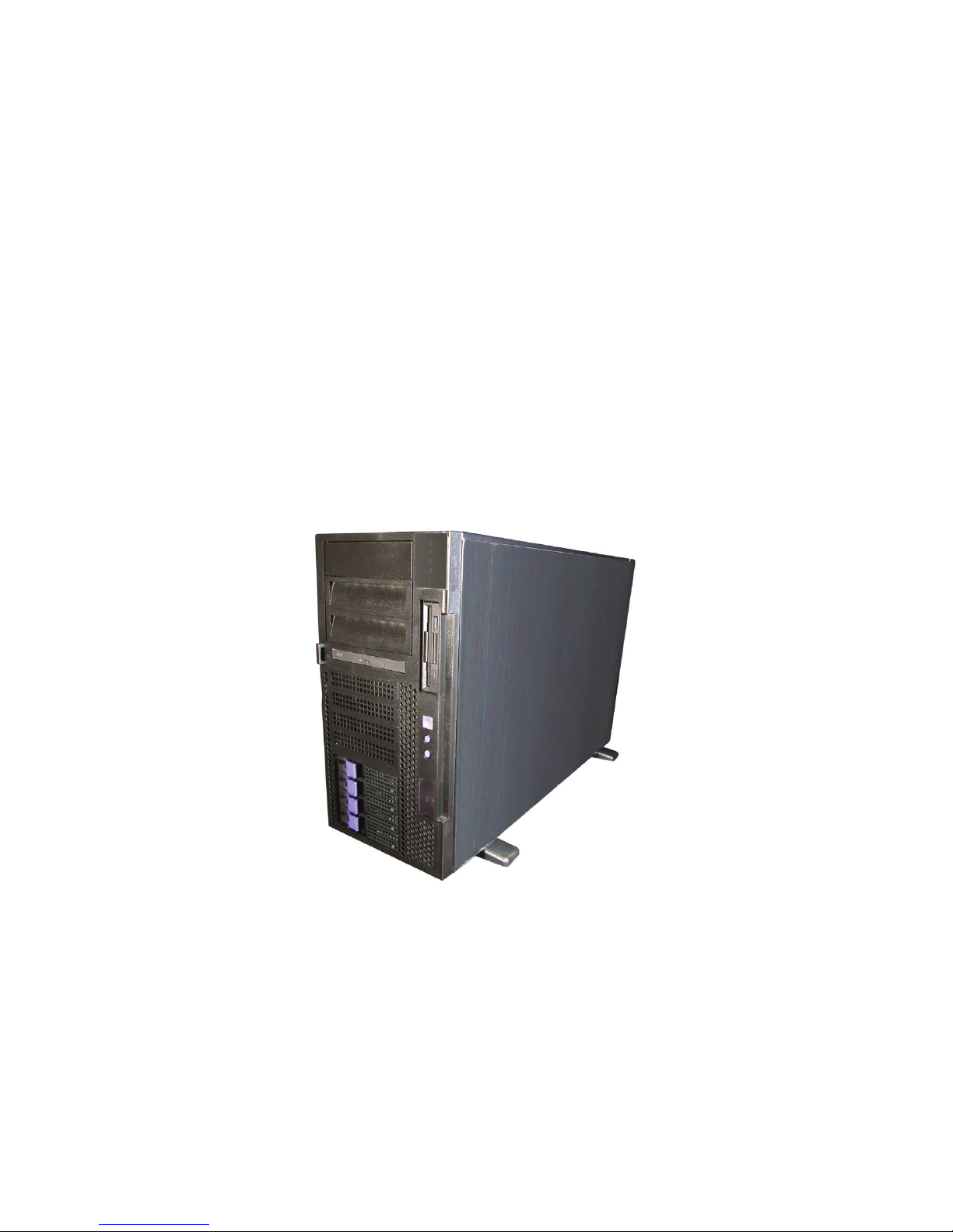
Congratulations on your purchase of the B4881V50S4H, rack
mountable or standalone, barebone system. This product
supports up to 8 AMD Opteron™ 800 series processors and
128 GB of registered DRAM, offering exceptional computing
power and simultaneous support of 32-bit and 64-bit applica-
tions. The following models and processors are supported:
Hot swap SATA or SCSI hard disk drives provide convenient
and resilient data storage capacity, and on-board Gigabit
Ethernet ports ensure high-speed data communication.
The rugged, rack mountable design includes eight HDD bays
and one slim CD-ROM bay.
WARNING: This product is very heavy and should not
be lifted by a single person. When installing this product in a rack, we recommend
that at least two people lift the server while
a third person guides it into place and
tightens the fixings. Always use a suitable
trolley or cart to transport the device.
Model Number Processor support
B4881V50S4H -4P Up to 4 CPUs
B4881V50S4H -8P Up to 8 CPUs

1.2 Features
2 Chapter 1: Overview
1.2 Features
Enclosure
• Industry standard pedestal or 19-inch
rack mountable, 5U chassis
• (4) hot swap SATA HDD bays
• (4) internal HDD bays (upgradable to
hot swap bays)
• (1) slim CD-ROM drive bay
• (1) standard FDD bay
• (3) 3.5-inch device bays
• Dimensions:
- 26.8 x 16.7 x 8.7-inch (5U)
- 680 x 425 x 220 mm
Storage Controller
• (2) dual port SATA II controllers
integrated in NVIDIA nForce4 Pro chip
• Support for up to four SATA HDDs
• Supports 3 Gb/s per port, 1.5 Gb/s in
each direction per channel
• Support for RAID 0, 1, 0+1, and
NVIDIA Morphing RAID
Motherboard
• Tyan Thunder K8QW Pro S4881
• SSI EEB 3.5 footprint (13 x 16-inch)
Processors
• Support for up to eight AMD®
Opteron™ 800 series processors.
CPU board (8 processor only)
• Tyan M4881
• 13 x 12-inch
Chipset
• NVIDIA nForce4 Professional +
AMD-8131 HyperTransport PCI-X
tunnel
• Winbond W83627HF Super I/O chip
• ADT7468 hardware monitor IC
BIOS
• Phoenix 8Mbit LPC Flash ROM
• Serial Console Redirect
• USB device boot
• ACPI 2.0 power management support
Memory
• (16) 184-pin 2.5V DDR DIMM
sockets on S4881 motherboard
• (16) 184-pin 2.5V DDR DIMM
sockets on M4881 CPU board
• Up to 128 GB of registered, ECC
DDR400/333/266 memory
Networking
• (2) Gbit Ethernet ports (Broadcom®
BCM5704 dual port controller)
Video
•ATI® Rage™ XL PCI Graphics
controller
• 8 MB Frame Buffer video memory
Expansion slots
• (2) 16 PCI Express slots (one with x4
signal)
• (2) Independent 64-bit PCI-X bus
• (1) 64-bit 133 MHz (3.3V) PCI-X slot
• (2) 64-bit 100 MHz (3.3V) PCI-X slot
Server Management
• Automatic fan speed control
• Chassis intrusion alert
• Tyan Server Management Support
• Tyan SMDC, IMPI v 1.5 compliant
remote server management kit (option)
Back I/O ports
• PS/2 mouse and keyboard ports
• (2) RJ-45 10/100/100BaseT with
activity LED
• (2) USB 2.0 ports
• (1) 9-pin UART serial port
• (1) 15-pin VGA port
Front panel
• (2) USB 2.0 ports
• LED indicators (power, LAN x2, HDD
activity, ID)
• Switches (power, reset, ID)
Power supply
• (4) redundant power supply modules, 4
x 500 watt.
Regulatory
• FCC Class A (declaration of
conformity)
• CE (declaration of conformity)
1.3 Unpacking
Chapter 1: Overview 3
1.3 Unpacking
This section describes the B4881V50S4H package contents
and accessories.
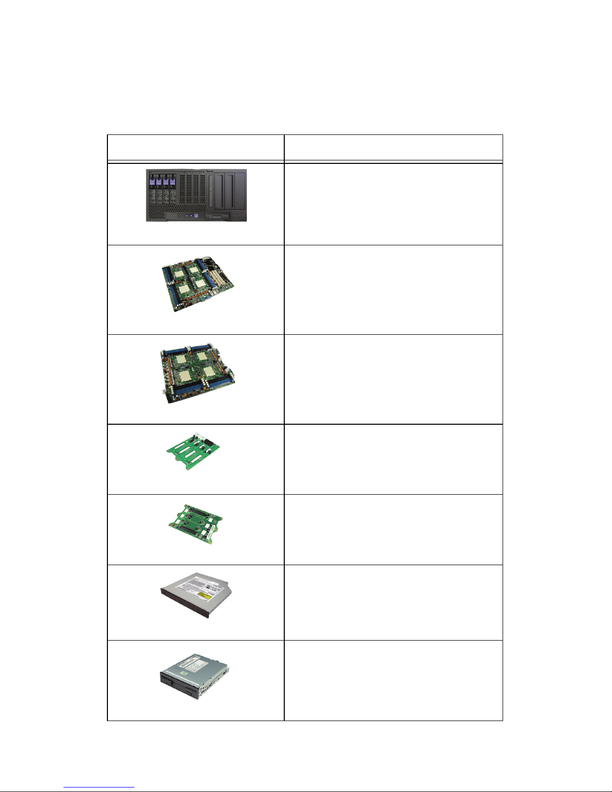
1.3.1 Box contents
Component Description
Industry standard 5U chassis with eight
HDD bays and three further 5.24-inch
device bays
Tyan S4881 and M4881 motherboard
(pre-installed)
Tyan M4881 CPU board (8 processor
only) and two HyperTransport (HT)
cards (required to mount CPU board to
motherboard)
SATA backplane (pre-installed)
SCSI backplane (option)
24x slim CD-ROM (pre-installed)
Floppy disk drive (pre-installed)
1.3 Unpacking
4 Chapter 1: Overview
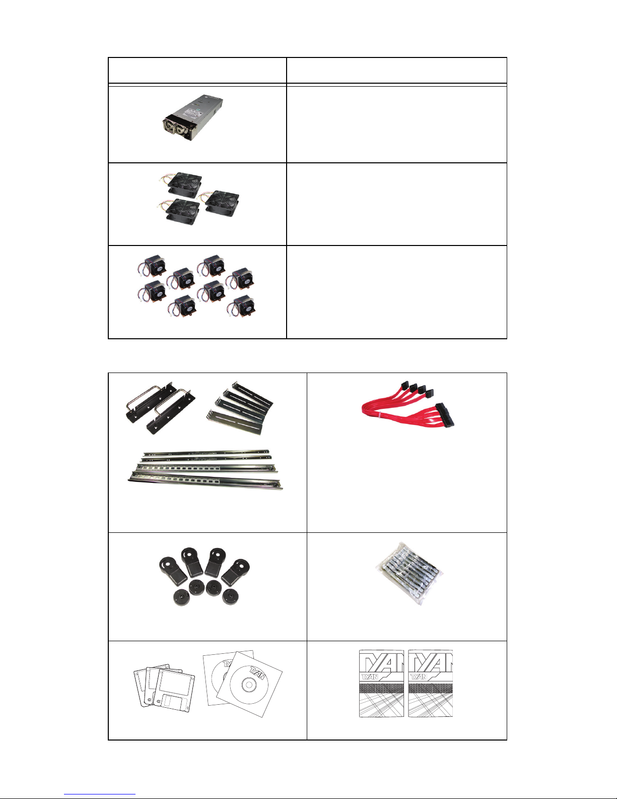
1.3.2 Accessories
Up to four 500W hot-swap power supplies
Three system cooling fans (preinstalled) 120 x 120 x 38 mm
Four or eight processor heatsink
assemblies (pre-installed)
Rack mounting kit; mounting ears,
and rail assembly
Cable set:
• (4) SATA cables
• (1) 40-pin IDE ribbon cable
• (1) 34-pin FDD ribbon cable
• (8) power cord 4 x US, 4 x EU
Four feet for standalone use
Four internal hard disk drive mounting kits
Driver CD and diskettes
Motherboard and system manual
Component Description
Adaptec
Window
48-10
S
ilic
o
n
R
D
riv
e
r
W
in
d
o
w
s
X
P
V
V
D
isk
Image
SiI3114
2000/
b
it
( 32 )
/2003
1.2.0.5
O
S
E
P
N
:
/
48-1000-132
Silicon
ID
E
D
riv
e
r
Windows
XP
V
V
D
isk
Image
SiI3114
2000/
bit
( 32 )
/2003
1.2.0.5
OSE P N:
/
48-1000-132
WWW.tyan.com
01010
Basic
D
riv
e
r
Ver
sio
n
WW
W
.ty
an.com
M
2
.0
CD
01010
S2882
K8S Pro AJS
#D 1528 - 100
Revision 1.0
High Performance Motherboard
User's Manual
2U Server Platform
B2882
Transport TA26
ID : 1540 - 100
Revision 1.0
Hardware
Installation Guide
1.3 Unpacking
Chapter 1: Overview 5
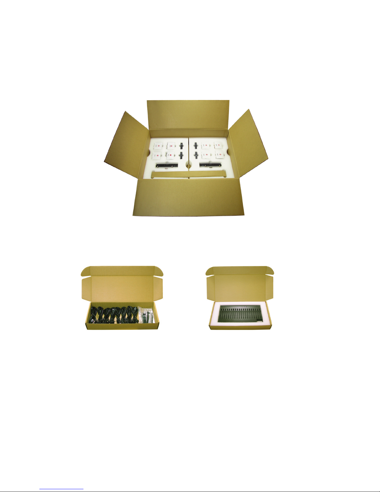
1.3.3 Opening the box
Open the box carefully and ensure that all components are
present and undamaged. The product should arrive packaged as illustrated below.
Contact your distributor if anything is missing or appears
damaged.
Power cables and disk
mounting kit
Accessory pack
Server door
1.4 About the product
6 Chapter 1: Overview
1.4 About the product
This section contains hardware diagrams and a block diagram of the B4881V50S4H system.
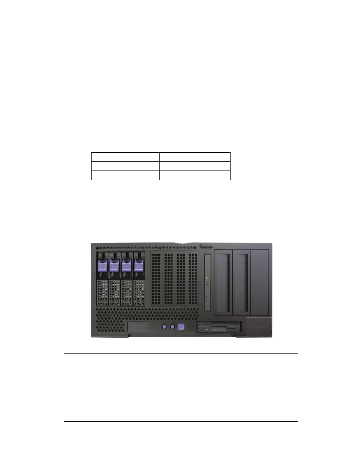
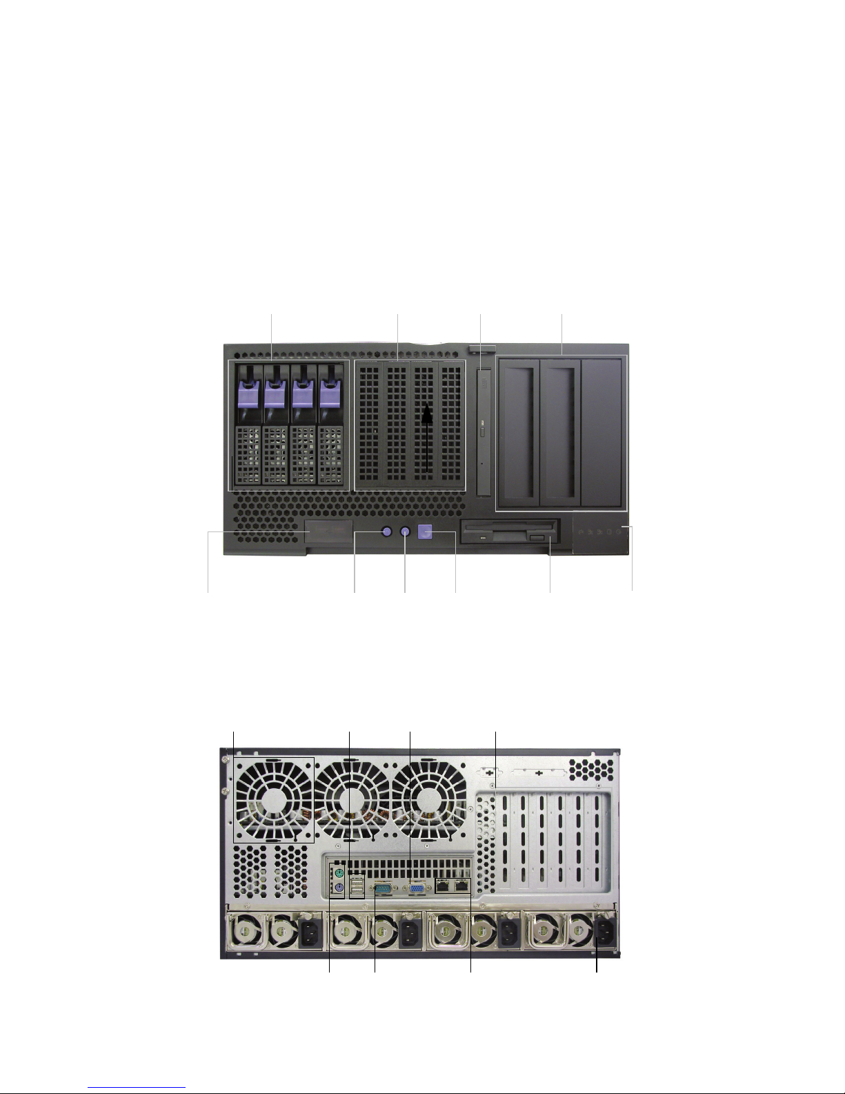
1.4.1 System front view and front panel
See the diagram below for details of the front panel indicators
and switches.
1.4.2 System rear view
USB ports Reset
id
Power
Floppy
disk drive
LED
control
panel
5.25-inch
device
bays
Slim
CD-ROM
drive
Internal
HDD
bays
Hotswap
HDD
bays
Cooling
fan
AC inputRJ45
ports
Serial port
(COM 1)
Expansion
slots
Stacked keyboard
and mouse ports
USB
ports
VGA
port
1.4 About the product
Chapter 1: Overview 7
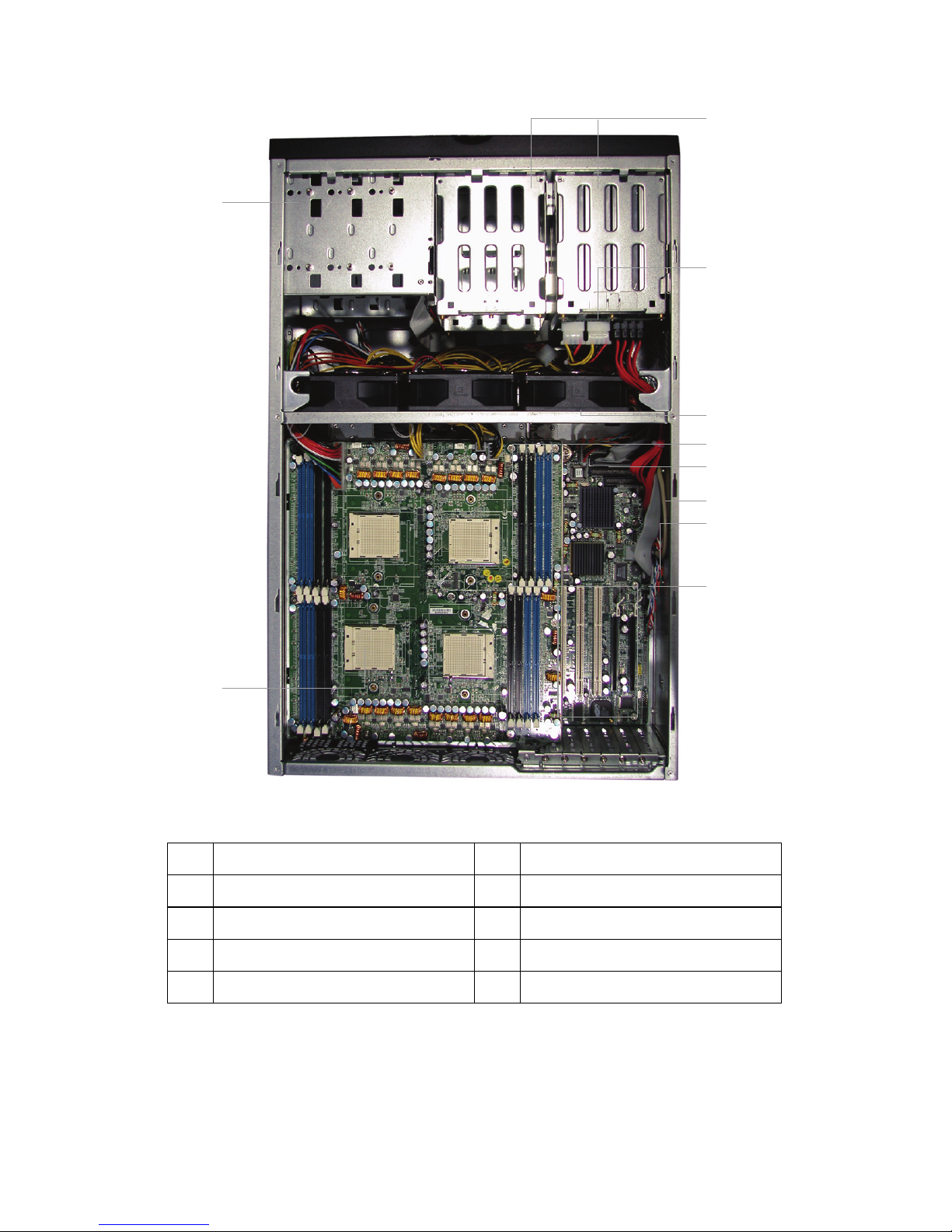
1.4.3 System internal view
1 Hard disk drive cradles 6 SATA ports
2 SATA backplane 7 Floppy disk drive socket
3 System cooling fans 8 PCI slots
4 Memory bank 9 CPU
5 IDE socket (CD-ROM drive) 10 Cradle for 5.25-inch devices
1
9
8
2
3
4
5
6
7
10
1.4 About the product
8 Chapter 1: Overview
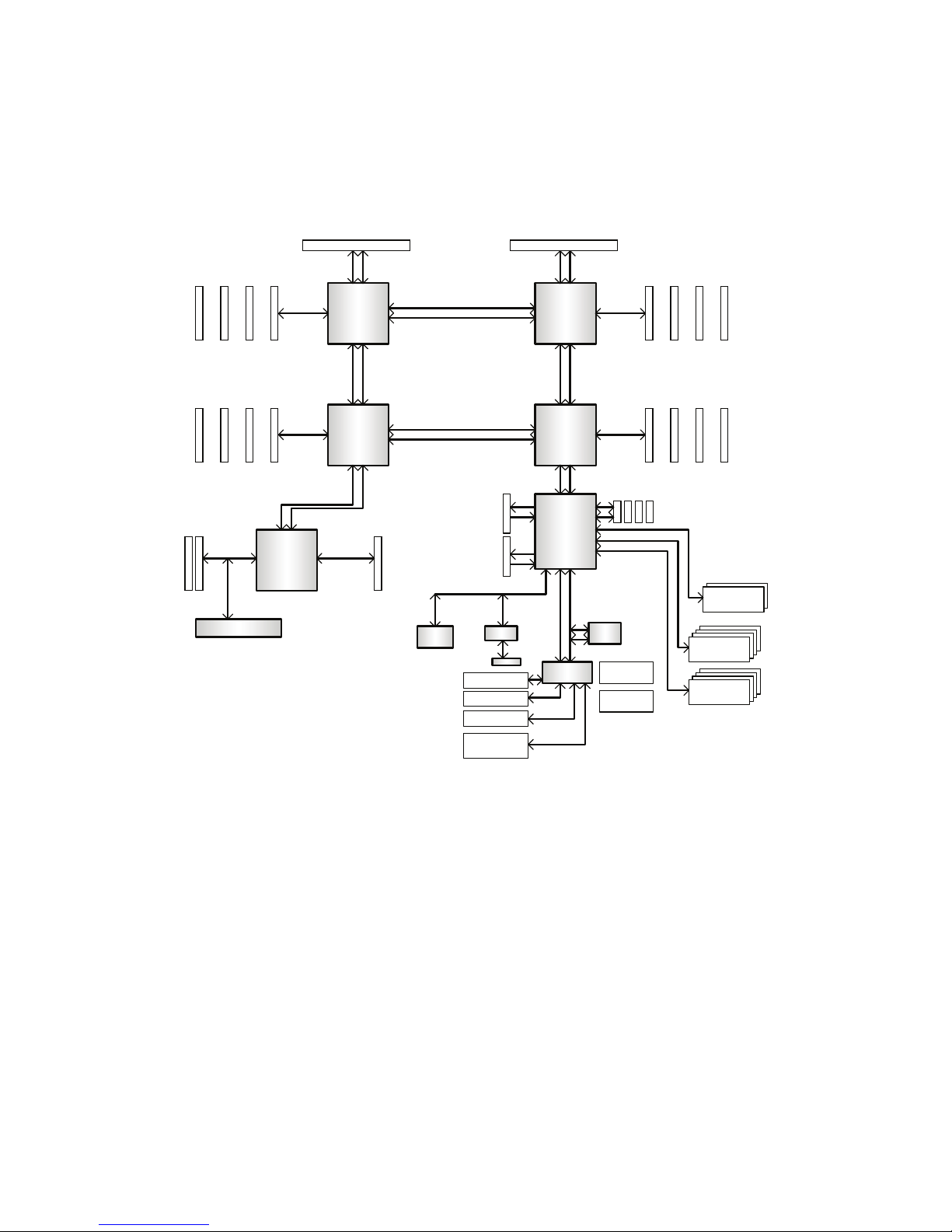
1.4.4 Motherboard block diagram
DDR266/333
144-Bit
DDR266/333
144-Bit
DDR266/333
144-Bit
DDR266/333
144-Bit
184 pin
DIMM3
184 pin
DIMM2
184 pin
DIMM1
184 pin
DIMM0
184 pin
DIMM0
184 pin
DIMM1
184 pin
DIMM2
184 pin
DIMM3
184 pin
DIMM0
184 pin
DIMM1
184 pin
DIMM2
184 pin
DIMM3
184 pin
DIMM3
184 pin
DIMM2
184 pin
DIMM1
184 pin
DIMM0
HT Connector( connect to CPU board) HT Connector( connect to CPU board)
16x16 Hyper Transport@1600MT/s
16x16 Hyper Transport@1600MT/s
16x16 Hyper Transport@1600MT/s
OUT
IN
OUT
IN
16x16 Hyper Transport@1600MT/s
16x16 Hyper Transport@1600MT/s
16x16 Hyper Transport@1600MT/s
PCI-X Slot PCI-X Slot
BUS A
BCM5704C Gigabit LAN two Port
Golem
AMD8131
Secondary CPU
H1
Floppy Disk Drive
LPC Super I/O
W83627HF
LPC ROM
LPC
bus
PCI-Express
x 16 slot
PCI Express X16 slotll
( X4 Signals)
4 SATA ports
EIDE(ATA/133) x2
USB2.0 x 2rear panel
USB2.0 x 6 front
panel headers
PS/ Kstboard & Mouse
64-Bit/100/66MHz 64-Bit/100/66MHz
BUS B
SERIAL port x 2
ATI RAGE XL
LINK 0
LINK 1
LINK 2
LINK 0
Third CPU
H2
LINK 2
LINK 1
LINK 0
Fourth
H3
LINK 1
LINK 2
LINK 0
Primary CPU
H0
Nvidia CK8-04 Pro
LINK 2
LINK 1
SATA
SATA
SATA
SATA
LINK 0
LINK 0
IEEE1394
Fport X2
32Bit/33MHz PCI BUS
SVMG interface
ADT7463 x2
Hardware Monitoring
Parallel Port
(Pin header)
1.4 About the product
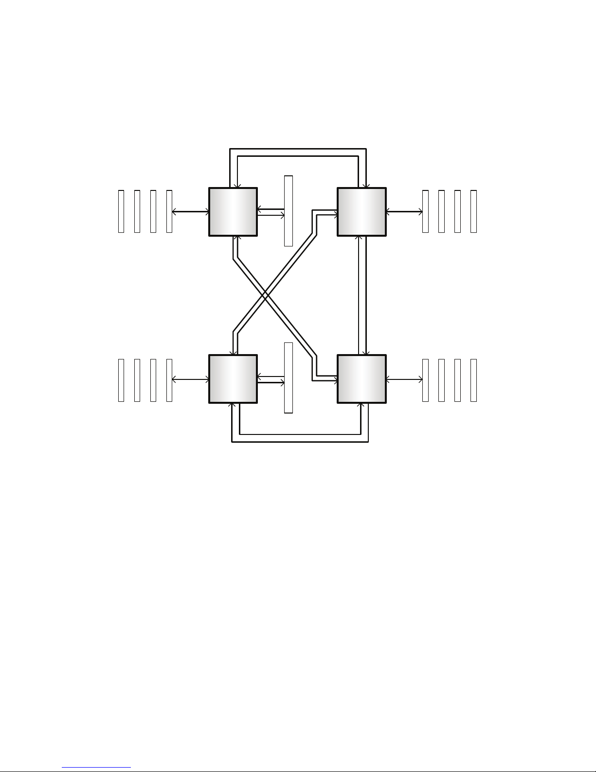
Chapter 1: Overview 9
1.4.5 CPU board block diagram
OUT IN
OUT
IN
IN
LINK 0 LINK 0
LINK 1 LINK 2
LINK 2
LINK 0
LINK 1
LINK 2
LINK 0
LINK 2
LINK 1
LINK 1
OUT
IN
IN OUT
IN OUTOUT IN
OUT IN
IN OUT
IN
OUT
OUT
OUT
IN
OUT IN
184 pin
DIMN 0
184 pin
DIMN 1
184 pin
DIMN 2
184 pin
DIMN 3
184 pin
DIMN 3
184 pin
DIMN 2
184 pin
DIMN 1
184 pin
DIMN 0
184 pin
DIMN 0
184 pin
DIMN 1
184 pin
DIMN 2
184 pin
DIMN 3
184 pin
DIMN 3
184 pin
DIMN 2
184 pin
DIMN 1
184 pin
DIMN 0
16x16 HyperTransport@1600MT/s 16x16 HyperTransport@1600MT/s
16x16 HyperTransport@1600MT/s
16x16 HyperTransport@1600MT/s
DDR266/333
144-Bit
DDR266/333
144-Bit
DDR266/333
144-Bit
DDR266/333
144-Bit
HT ConnectorHT Connector
H0
Primary CPU
H1
Secondary CPU
H3
Fourth
H2
Third CPU
(connect to Motherboard)(connect to Motherboard)
 Loading...