

Page 1
Transport TN68
B4989
Service Engineer’s Manual
Page 2

Page 3

PREFACE
Copyright
This publication, including all photographs, illustrations, and software, is
protected under international copyright laws, with all rights reserved.
Neither this manual, nor any material contained herein, may be reproduced
without written consent of manufacturer.
Copyright 2009 MiTAC International Corporation. All rights reserved.
TYAN® is a registered trademark of MiTAC International Corporation.
Version 2.00
Disclaimer
Information contained in this document is furnished by MiTAC Computer
Corporation and has been reviewed for accuracy and reliability prior to
printing. TYAN® assumes no liability whatsoever, and disclaims any
express or implied warranty, relating to sale and/or use of TYAN
®
products
including liability or warranties relating to fitness for a particular purpose or
merchantability. TYAN
®
retains the right to make changes to produce
descriptions and/or specifications at any time, without notice. In no event
will TYAN
®
be held liable for any direct or indirect, incidental or
consequential damage, loss of use, loss of data or other malady resulting
from errors or inaccuracies of information contained in this document.
Trademark Recognition
All registered and unregistered trademarks and company names contain-
-ed in this manual are property of their respective owners including, but not
limited to the following.
TYAN® is a trademark of MiTAC Computer Corporation.
AMD, Opteron, Athlon, and combinations thereof are trademarks of AMD
Corporation.
Phoenix, Phoenix BIOS, and combinations thereof are trademarks of
Phoenix Technologies.
Microsoft Windows is a trademark of Microsoft Corporation.
IBM, PC, AT and PS/2 are trademarks of IBM Corporation.
InfiniBand is a trademark of Mellanox Technologies.
Winbond is a trademark of Winbond Electronics Corporation.
Portable Document Format (PDF) is a trademark of Adobe Corporation.
i
Page 4

Federal Communication Commission (FCC)
Notice for the USA
Compliance Information Statement (Declaration of
Conformity Procedure) DoC FCC Part 15: This
device complies with part 15 of the FCC Rules
Operation is subject to the following conditions:
1) This device may not cause harmful interference;
2) This device must accept any interference received including
interference that may cause undesired operation. If this equipment
does cause harmful interference to radio or television reception,
which can be determined by turning the equipment off and on, the
user is encouraged to try one or more of the following measures:
– Reorient or relocate the receiving antenna.
– Increase the separation between the equipment and the receiver.
– Plug the equipment into an outlet on a circuit different from that of
the receiver.
Consult the dealer on an experienced radio/television technician for
help.
Notice for Canada
This apparatus complies with the Class B limits for radio interference as
specified in the Canadian Department of Communications Radio
Interference Regulations. (Cet appareil est conforme aux norms de
Classe B d’interference radio tel que specifie par le Ministere Canadien
des Communications dans les reglements d’ineteference radio.)
Notice for Europe (CE Mark)
This product is in conformity with the Council
Directive 89/336/EEC, 92/31/EEC (EMC).
CAUTION: Lithium battery included with this board. Do not puncture,
mutilate, or dispose of battery in fire. There will be danger of explosion if
battery is incorrectly replaced. Replace only with the same or equivalent
type recommended by manufacturer. Dispose of used battery according
to manufacturer instructions and in accordance with your local regulatio-
-ns.
ii
Page 5

About this Manual
This manual provides you with instructions on installing your Trans-
-port TN68-B4989. This Manual is intended for experienced users
and integrators with hardware knowledge of personal computers.
This manual consists of the following parts:
Chapter1:
Provides an introduction to the TN68-B4989 bare-
-bones, standard parts list, describes the external
components, gives a table of key components,
and provides block diagrams of the system.
Chapter2:
Covers procedures on installing the CPU,memory
modules, add on card and hard drives.
Chapter3:
Covers removal and replacement procedures for
pre-installed components.
Appendix :
Describes the differences between motherboard
BIOS and system BIOS; introduces how to install
the internal HDD, list the cable connection and
FRU part tables for reference of system setup;
and technical support
in case a problem arises
with your system.
For information on the mainboard, please refer to the attached
mainboard user’s manual. You can find the detailed description
about jumper and BIOS settings from the mainboard manual.
iii
Page 6

SAFETY INFORMATION
Before installing and using the Transport TN68-B4989, take note of the
following precautions:
·Read all instructions carefully.
·Do not place the unit on an unstable surface, cart, or stand.
·Do not block the slots and opening on the unit, which are provided for
ventilation.
·Only use the power source indicated on the marking label. If you are not
sure, contact the power company.
·The unit uses a three-wire ground cable, which is equipped with a third
pin to ground the unit and prevent electric shock. Do not defeat the pur-
-pose of this pin. If you outlet does not support this kind of plug, contact
your electrician to replace your obsolete outlet.
·Do not place anything on the power cord. Place the power cord where it
will not be in the way of foot traffic.
·Follow all warnings and cautions in this manual and on the unit case.
·Do not push objects in the ventilation slots as they may touch high volta-
-ge components and result in shock and damage to the components.
·When replacing parts, ensure that you use parts specified by the manuf-
-acturer.
·When service or repairs have been done, perform routine safety checks
to verify that the system is operating correctly.
·Avoid using the system near water, in direct sunlight, or near a heating
device.
·Cover the unit when not in use.
iv
Page 7

Table of Contents
Chapter 1: Overview
1.1 About the TYAN Transport TN68-B4989.................................... 1
1.2 Product Models........................................................................... 2
1.3 Features ..................................................................................... 3
1.4 Standard Parts List....................................................................10
1.4.1 Box Contents ......................................................................10
1.4.2 Accessories ........................................................................12
1.5 Optional Parts............................................................................13
1.6 About the Product......................................................................14
1.6.1 System Front View .............................................................
14
1.6.2 System Rear View ..............................................................14
1.6.3 LED Definitions.................................................................. 16
1.6.4 Motherboard (S4989) Layout ............................................ 17
1.6.5 Jumpers & Connectors...................................................... 18
1.6.6 System Block Diagram ...................................................... 19
1.6.7 Internal View.......................................................................20
Chapter 2: Setting Up
2.0.1 Before you Begin ................................................................23
2.0.2 Work Area...........................................................................23
2.0.3 Tools...................................................................................23
2.0.4 Precautions
.........................................................................24
2.1 Installing Motherboard Components .........................................25
2.1.1 Removing the Chassis Cover.............................................25
2.1.2 Installing the CPU and Heatsink.........................................26
2.1.3 Installing the Memory .........................................................30
2.1.4 Installing Expansion Cards.................................................32
2.1.5 Installing Hard Drives .........................................................36
2.2 Rack Mounting...........................................................................38
2.2.1 Installing the Server in a Rack............................................38
2.2.2 Installing the inner Rails to the Chassis .............................39
v
Page 8

2.2.3 Installing the Outer Rails to the Rack .................................40
2.2.4 Rack mounting the Server..................................................40
Chapter 3: Replacing Pre-Installed Components
3.1 Introduction................................................................................43
3.2 Disassembly Flowchart..............................................................43
3.3 Removing the Cover..................................................................45
3.4 Replacing Motherboard Components........................................45
3.4.1 Disconnecting All Motherboard Cables ..............................45
3.4.2 Removing the Motherboard................................................47
3.5 Replacing the Slim DVD-ROM ..................................................49
3.6 Replacing the LED Control Board .............................................51
3.6.1 M1003 LED Control Board Features..................................53
3.6.2 M1003 LED Control Board Connector Pin Definition .........53
3.7 Replacing the System Fan ........................................................55
3.8 Replacing the M1022 Fan Board...............................................57
3.8.1 M1022 Fan Board Features ...............................................59
3.8.2 M1022 Fan Board Connector Pin Definition.......................60
3.9 Replacing the M1229-PT HDD Backplane ................................61
3.9.1 M1229-PT HDD Backplane Features.................................63
3.9.2 M1229-PT HDD Backplane Connector Pin Definitions ......65
3.10 Replacing the Power Supply......................................................67
3.10.1 Replace the power supply ................................................67
3.10.2 Replace the power board M1029 .....................................67
3.10.3 M1029 power board Features ..........................................69
Appendix I: BIOS Differences
Appendix II: Installing the Internal 2.5”HDD
Appendix III: Cable Connection Tables
Appendix IV: FRU Parts Table
Appendix V: Technical Support
vi
Page 9
Chapter 1: Overview
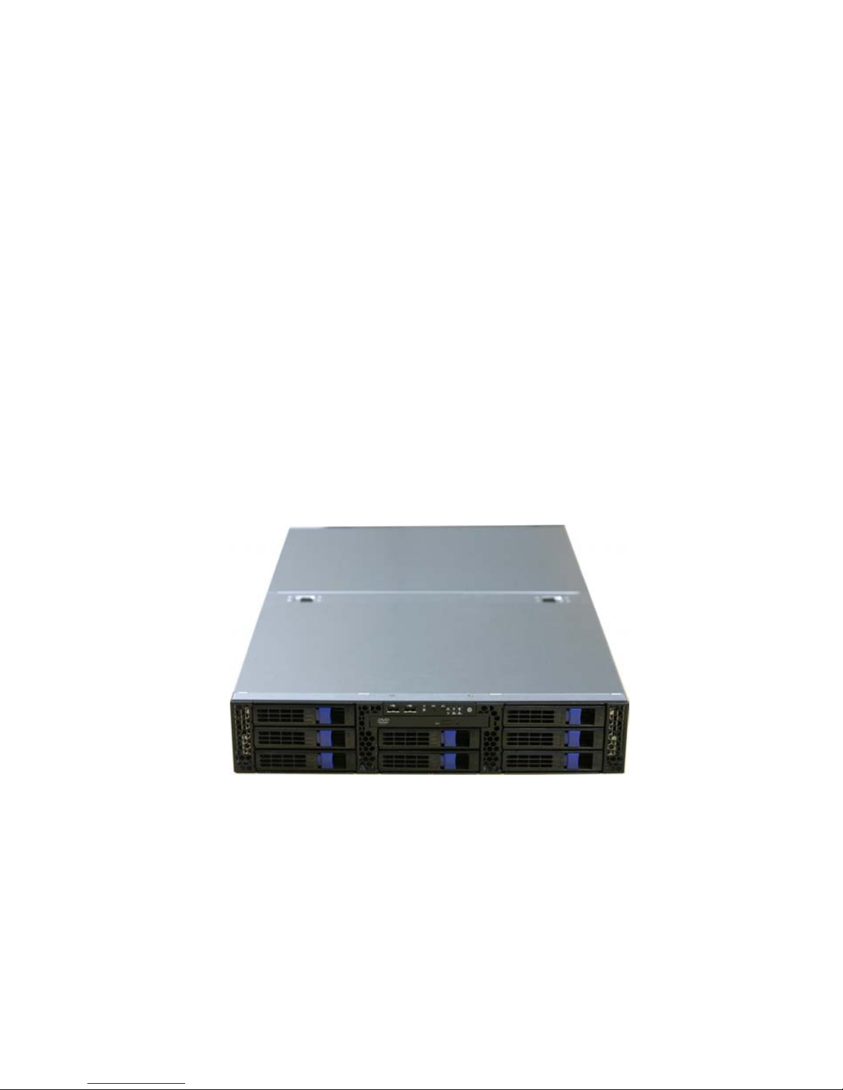
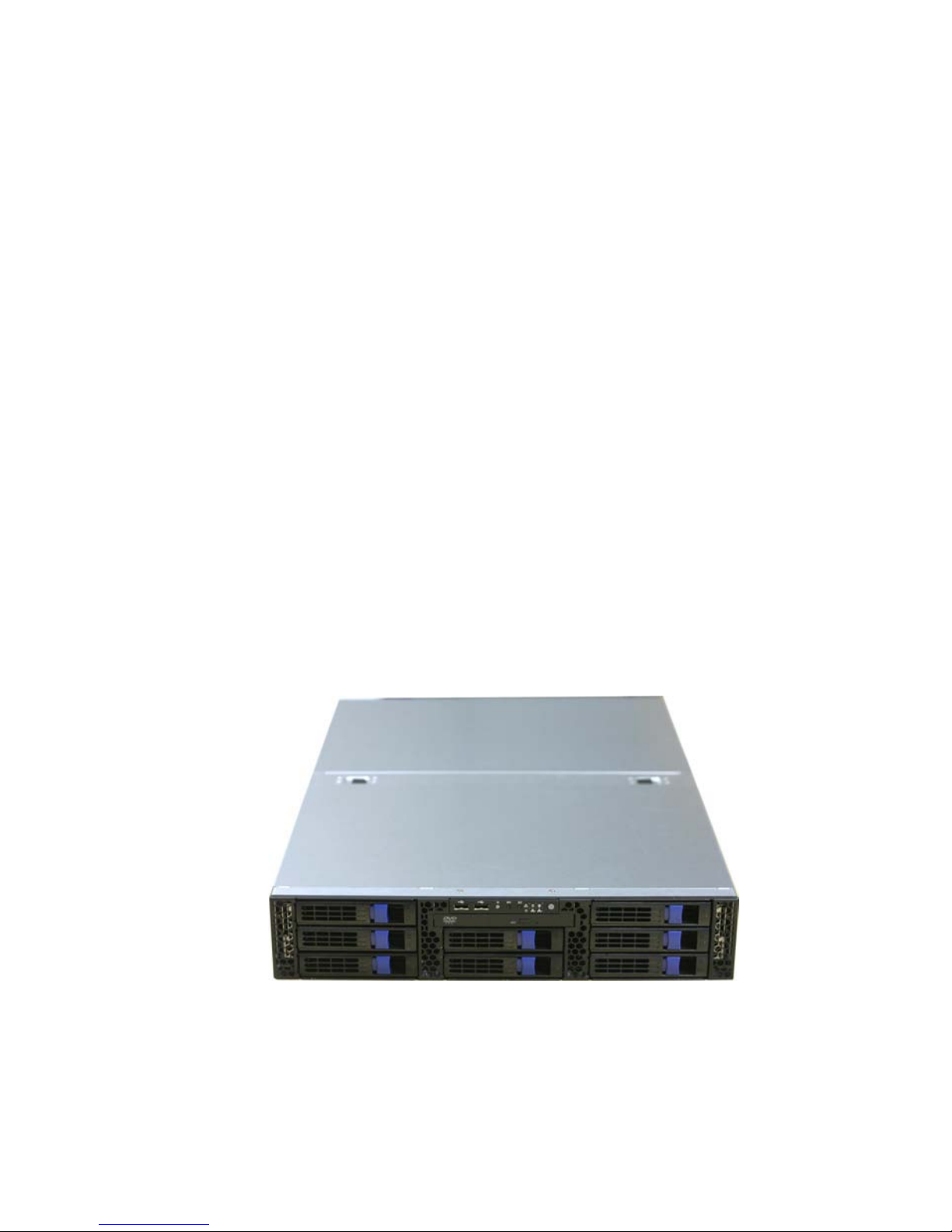
1.1 About the TYAN Transport TN68-B4989
Congratulations on your purchase of the TYAN® Transport TN68-B4989,
a highly-optimized rack-mountable barebone system. The Transport TN
68-B4989 is designed to support four AMD® Opteron™ 8000 series Dual-
-core and Quad-core 1207-pin processors and up to 32DIMMs, providing
a rich feature set and incredible performance. Leveraging advanced tech-
-nology from AMD, the Transport TN68-B4989 server system is capable
of offering scalable 32 and 64-bit computing, high-bandwidth memory
design, and lightning-fast PCI-E bus implementation. The Transport TN68
-B4989 not only empowers your company in today’s demanding IT envir-
-onment but also offers a smooth path for future application usage.
TYAN® is also proud to deliver the Transport TN68-B4989 in flavor while
supporting up to eight hot-swap hard drives and one slim ODD. The
Transport TN68-B4989 uses TYAN
®
’s latest chassis featuring a robust
structure and a solid mechanical enclosure. All of this provides the
Transport TN68-B4989 the power and flexibility to meet the needs of
nearly any server application.
Chapter 1: Overview
1
Page 10
1.2 Product Models
Model HDD Bays Power supply
B4989T68W8HR-SI
Removable, 8 HDDs
1400W (2+1)
Redundant PSU
B4989T68W8HR-LE
Removable, 8 HDDs
1400W (2+1)
Redundant PSU
2
Chapter 1: Overview
Page 11

1.3 Features
Transport TN68 B4989 (B4989T68W8HR-SI)
Form Factor 2U Rackmount
Chassis Name TN68
Dimension (D x W x H) 26.8" x 16.9" x 3.4" (680 x 430 x 87mm)
Motherboard S4989WG2NR-SI
Board Dimension MEB, 13"x16.2" (330x411mm)
System
Gross Weight 32 kg
Buttons (1) PWR / (1) RST / (1) NMI / (1) ID
LEDs (1) PWR / (1) HDD / (2) LAN / (1) ID / (1) Warning
Front Panel
I/O Ports (2) USB
Type / QTY 3.5" Hot-Swap / (8)
External Drive
Bay
Supported HDD
Interface
1st priority: SAS / 2st priority: SATA II
FAN (8) hot-swappable 6cm fans + (1) 6cm system fan System
Cooling
Configuration
Air Duct (1) Air duct
Type of ODD / QTY Slim-type DVD-ROM / (1)
Peripherals
Note:
(1) internal 2.5" HDD tray if w/o DVD-ROM
(optional)
Type EPS12V
Input Range Full-range AC(100-240V)
Frequency 60 Hertz
Output Watts 1400 Watts
Efficiency 80-plus
Power Supply
Redundancy 2+1
Supported CPU Series
AMD 8000 series Dual-Core/ Quad-core
processors
/ Support AMD Dual Dynamic Power
Management (DDPM) feature / Support AMD
HyperTransport (HT1 and HT3) Technology
Socket Type / QTY LGA 1207-pin / (4)
Thermal Design Power
(TDP) wattage
Quad core up to 115W, dual core up to 95W
Processor
System Bus (MHz) 4.4GT/s HyperTransport inter-processor link
Chipset NVIDIA NFP3600 / NFP3050
Super I/O Winbond W83627HG-AW
PCI-E bridge Pericom PI7C9X130
Chipset
HW monitor (1)W83793G +(2) ADT7476
Memory Supported DIMM QTY (32) DIMM sockets
Chapter 1: Overview
3
Page 12

DIMM Type / Speed
Registered ECC DDR2 800/667/533/400
(800MHz DDR2 speed support available
only at 4xDIMMs per CPU or less)
((8) Dual Rank memory per CPU will have a
maximum memory speed of 533MHz)
Capacity Up to 256GB
Memory channel 2 Channels
Memory
Memory voltage 1.8V
PCI-E (2) PCI-E x8 slots / (2) PCI-E x16 slots
PCI-X (2) PCI-X 133/100MHz slots
Expansion
Slots
Note: Total (6) expansion slots support low profile cards
Port QTY (3)
Controller Intel 82571EB dual-port GbE LAN controller
LAN
PHY
Davicom DM9161 10/100 PHY (dedicated for
IPMI connection)
Connector (2) Mini-SAS connectors (support 8 ports)
Controller LSI SAS1068E
Speed 3.0 Gb/s
SAS
RAID RAID 0/1/1E (LSI Integrated RAID)
Connector (6) SATAII
Controller MCP55
Speed 3.0 Gb/s
Storage
SATA
RAID RAID 0/1/0+1/5
Connector type D-Sub 15-pin
Resolution 1600x1200@60Hz
Chipset XGI Z9s
Graphic
Video RAM 32MB
USB 4 ports ( 2 at front, 2 at rear)
COM 1 port
PS/2 1 stacked connector
VGA 1 port
I/O Ports
RJ-45 3 ports (1 port for OPMA)
Chipset (1)W83793G +(2) ADT7476/ W83627HG-AW
Voltage
Monitors voltage for CPU, memory, chipset &
power supply
Fan
(8) 4-pin headers on Fan board / (1) 4-pin header
on MB
Temperature
Monitors temperature for CPU & system
environment
LED
Over temperature warning indicator / Fan & PSU
fail LED indicator
System
Monitoring
Others
Chassis intrusion detection / Watch Dog timer
support
4
Chapter 1: Overview
Page 13

Onboard Chipset Onboard Kira 100
Server
Management
Kira 100 Feature
KIRA 100 (Single Chip KVM/IP+IPMI processor) /
KVM over IP / Video output over LAN
(1280x1024) / USB2 high speed interface /
Remote CDROM (media) redirect / Remote power
on/off, reset and soft off
Brand / ROM size AMI / 8Mbit
BIOS
Feature
Plug and Play (PnP) /PCI2.3 /WfM2.0
/SMBIOS2.3 /PXE Boot / ACPI 2.0 power
management /Power on mode after power
recovery / User-configurable H/W monitoring /
Auto-configurable of hard disk types / Multiple
boot options
Operation
System
OS supported list Please refer to our OS supported list.
FCC (Doc) Class B
Regulation
CE (Doc) Yes
Operating Temp 10° C ~ 35° C (50° F~ 95° F)
Non-operating Temp - 40° C ~ 70° C (-40° F ~ 158° F)
Operating
Environment
In/Non-operating
Humidity
90%, non-condensing at 35° C
RoHS RoHS 6/6 Complaint Yes
Motherboard (1) S4989WG2NR-SI
Manual (1) User's manual / (1) Quick Ref. Guide
Installation CD (1) TYAN installation CD
CPU CEK (4) CPU backplates
Chassis Unit (1) CCHA-0300, TN68 2U chassis
Peripheral (1) CDVD-0060, slim type DVD-ROM
Cover
(1) CCCV-0160, Front Top cover for TN68 chassis
/ (1) CCCV-0161, Rear Top cover for TN68
chassis
HDD Tray (8) CHDT-0130, Removable 3.5" HDD Tray
Heatsink / Cooler
(1) CFAN-0094, 6 cm fan / (4) CHSK-0310, LGA
1207 pin CPU heatsink / (8) CFAN-0330, 6 cm
fans / (1) CADT-0270, air duct
Rail kit (1) CRAL-0120, sliding rail kit for TN68
Mounting Ear (1) CEAR-0130, mounting ear kit
Front Panel board (1) M1003-ID-RS, front panel board
Backplane
(1) M1022, Fan adapter board / (1) M1229-PT,
SAS/SATA 8 port HDD backplane / (1) M1029,
3-port power backplane
Package
Contains
Power Supply
(3) CPSU-0350, 700W PSU module for 2+1 Red.
power solution
Chapter 1: Overview
5
Page 14
SATA (2) CCBL-0326, SATA signal cables
SAS (2) CCBL-067H, Mini-SAS cables
DVD-ROM
(1) CCBL-0422, SATA DVD-ROM power cable /
(1) CCBL-067K, DVD-ROM SAS cable
USB
(1) CCBL-0357, USB cable / (1) CCBL-035G, FP
USB cable
FAN
(1) CCBL-146F, Fan BP 2x2P power cable,
300mm / (1) CCBL-146G, Fan BP small 4P power
cable / (1) CCBL-039H, fan control cable
Front Panel
(1) CCBL-072I, FP2 cable / (1) CCBL-072J, FP
cable (for M1229 R03) / (1) CCBL-072K, FP cable
(for M1229 R04) / (1) CCBL-072H, FP1 cable
Power Cord
(3) CCBL-0310, US type power cords / (3)
CCBL-0300, EU type power cords
Package
Contains
Cable
Others
(1) CCBL-146A, MB 2x12P power cable / (1)
CCBL-146B, MB 2x4P power cable / (1)
CCBL-146C, MB 2x2P power cable / (1)
CCBL-146D, HDD BP 2x6P power cable / (1)
CCBL-146E, HDD BP 2x2P power cable, 350mm
/ (1) CCBL-0612, SMbus cable
Drive Tray (1) CHDT-0111, Internal 2.5" HDD tray
Peripheral (1) CMPT-0170, TN68 DVD dummy cover
Optional
accessories
for future
upgrade
Cable (1) CCBL-1070, internal 2.5" HDD power cable
Transport TN68 B4989 (B4989T68W8HR-LE)
Form Factor 2U Rackmount
Chassis Name TN68
Dimension (D x W x H) 26.8" x 16.9" x 3.4" (680 x 430 x 87mm)
Motherboard S4989WG2NR-LE
Board Dimension MEB, 13"x16.2" (330x411mm)
System
Gross Weight 32 kg
Buttons (1) PWR / (1) RST / (1) NMI / (1) ID
LEDs (1) PWR / (1) HDD / (2) LAN / (1) ID / (1) Warning
Front Panel
I/O Ports (2) USB
Type / QTY 3.5" Hot-Swap / (8)
External
Drive Bay
Supported HDD
Interface
1st priority: SAS / 2st priority: SATA II
FAN (8) hot-swappable 6cm fans + (1) 6cm system fanSystem
Cooling
Configuration
Air Duct (1) Air duct
Type of ODD / QTY Slim-type DVD-ROM / (1)
Peripherals
Note:
(1) internal 2.5" HDD tray if w/o DVD-ROM
(optional)
6
Chapter 1: Overview
Page 15
Type EPS12V
Input Range Full-range AC(100-240V)
Frequency 60 Hertz
Output Watts 1400 Watts
Efficiency 80-plus
Power Supply
Redundancy 2+1
Supported CPU
Series
AMD 8000 series Dual-Core/ Quad-core
processors
/ Support AMD Dual Dynamic Power
Management (DDPM) feature / Support AMD
HyperTransport (HT1 and HT3) Technology
Socket Type / QTY LGA 1207-pin / (4)
Thermal Design
Power (TDP) wattage
Quad core up to 115W, dual core up to 95W
Processor
System Bus (MHz) 4.4GT/s HyperTransport inter-processor link
Chipset NVIDIA NFP3600 / NFP3050
Super I/O Winbond W83627HG-AW
PCI-E bridge Pericom PI7C9X130
Chipset
HW monitor (1)W83793G +(2) ADT7476
Supported DIMM QTY (32) DIMM sockets
DIMM Type / Speed
Registered ECC DDR2 800/667/533/400
(800MHz DDR2 speed support available
only at 4xDIMMs per CPU or less)
((8) Dual Rank memory per CPU will have a
maximum memory speed of 533MHz)
Capacity Up to 256GB
Memory channel 2 Channels
Memory
Memory voltage 1.8V
PCI-E (2) PCI-E x8 slots or (1) PCI-E x16 slots
Pre-install TYAN Riser
Card
Install M2089, (2) PCI-E x16 slots w/ x8 signal, 2U
riser card (left), support full profile add on cards
Expansion
Slots
Note:
M2090 optional, (1) PCI-E x16 slots, 2U riser card
(left), support full profile add on card
Port QTY (3)
Controller Intel 82571EB dual-port GbE LAN controller
LAN
PHY
Davicom DM9161 10/100 PHY (dedicated for IPMI
connection)
Connector (2) Mini-SAS connectors (support 8 ports)
Controller LSI SAS1068E
Speed 3.0 Gb/s
SAS
RAID RAID 0/1/1E (LSI Integrated RAID)
Connector (6) SATAII
Storage
SATA
Controller MCP55
Chapter 1: Overview
7
Page 16
Speed 3.0 Gb/s
SATA
RAID RAID 0/1/0+1/5
D-Sub 15-pin
1600x1200@60Hz
Chipset XGI Z9s
Graphic
Video RAM 32MB
USB 4 ports ( 2 at front, 2 at rear)
COM 1 port
PS/2 1 stacked connector
VGA 1 port
I/O Ports
RJ-45 3 ports (1 port for OPMA)
Chipset (1)W83793G +(2) ADT7476/ W83627HG-AW
Voltage
Monitors voltage for CPU, memory, chipset &
power supply
Fan
(8) 4-pin headers on Fan board / (1) 4-pin header
on MB
Temperature
Monitors temperature for CPU & system
environment
LED
Over temperature warning indicator / Fan & PSU
fail LED indicator
System
Monitoring
Others
Chassis intrusion detection / Watch Dog timer
support
Onboard Chipset Onboard Kira 100
Server
Management
Kira 100 Feature
KIRA 100 (Single Chip KVM/IP+IPMI processor) /
KVM over IP / Video output over LAN (1280x1024)
/ USB2 high speed interface / Remote CDROM
(media) redirect / Remote power on/off, reset and
soft off
Brand / ROM size AMI / 8Mbit
BIOS
Feature
Plug and Play (PnP) /PCI2.3 /WfM2.0 /SMBIOS2.3
/PXE Boot / ACPI 2.0 power management /Power
on mode after power recovery / User-configurable
H/W monitoring / Auto-configurable of hard disk
types / Multiple boot options
Operation
System
OS supported list Please refer to our OS supported list.
FCC (Doc) Class B
Regulation
CE (Doc) Yes
Operating Temp 10° C ~ 35° C (50° F~ 95° F)
Non-operating Temp - 40° C ~ 70° C (-40° F ~ 158° F)
Operating
Environment
In/Non-operating
Humidity
90%, non-condensing at 35° C
RoHS RoHS 6/6 Complaint Yes
Package
Motherboard (1) S4989WG2NR-LE
8
Chapter 1: Overview
Page 17

Manual (1) User's manual / (1) Quick Ref. Guide
Installation CD (1) TYAN installation CD
CPU CEK (4) CPU backplates
Chassis Unit (1) CCHA-0360, TN68-LE 2U chassis
Peripheral (1) CDVD-0060, slim type DVD-ROM
Cover
(1) CCCV-0160, Front Top cover for TN68 chassis
/ (1) CCCV-0161, Rear Top cover for TN68
chassis
HDD Tray (8) CHDT-0130, Removable 3.5" HDD Tray
Heatsink / Cooler
(1) CFAN-0094, 6 cm fan / (4) CHSK-0310, LGA
1207 pin CPU heatsink / (8) CFAN-0330, 6 cm
fans / (1) CADT-0270, air duct
Rail kit (1) CRAL-0120, sliding rail kit for TN68
Mounting Ear (1) CEAR-0130, mounting ear kit
Front Panel board (1) M1003-ID-RS, front panel board
Backplane
(1) M1022, Fan adapter board / (1) M1229-PT,
SAS/SATA 8 port HDD backplane / (1) M1029,
3-port power backplane
Power Supply
(3) CPSU-0350, 700W PSU module for 2+1 Red.
power solution
SATA (2) CCBL-0326, SATA signal cables
SAS (2) CCBL-067H, Mini-SAS cables
DVD-ROM
(1) CCBL-0422, SATA DVD-ROM power cable /
(1) CCBL-067K, DVD-ROM SAS cable
USB
(1) CCBL-0357, USB cable / (1) CCBL-035G, FP
USB cable
FAN
(1) CCBL-146F, Fan BP 2x2P power cable,
300mm / (1) CCBL-146G, Fan BP small 4P power
cable / (1) CCBL-039H, fan control cable
Front Panel
(1) CCBL-072I, FP2 cable / (1) CCBL-072J, FP
cable (for M1229 R03) / (1) CCBL-072K, FP cable
(for M1229 R04) / (1) CCBL-072H, FP1 cable
Power Cord
(3) CCBL-0310, US type power cords / (3)
CCBL-0300, EU type power cords
Contains
Cable
Others
(1) CCBL-146A, MB 2x12P power cable / (1)
CCBL-146B, MB 2x4P power cable / (1)
CCBL-146C, MB 2x2P power cable / (1)
CCBL-146D, HDD BP 2x6P power cable / (1)
CCBL-146E, HDD BP 2x2P power cable, 350mm /
(1) CCBL-0612, SMbus cable
Drive Tray (1) CHDT-0111, Internal 2.5" HDD tray
Peripheral (1) CMPT-0170, TN68 DVD dummy cover
Optional
accessories
for future
upgrade
Cable (1) CCBL-1070, internal 2.5" HDD power cable
Chapter 1: Overview
9
Page 18
1.4 Standard Parts List
This section describes the Transport TN68-B4989 package contents
and accessories. Open the box carefully and ensure that all
components are present and undamaged. The product should arrive
packaged as illustrated below.
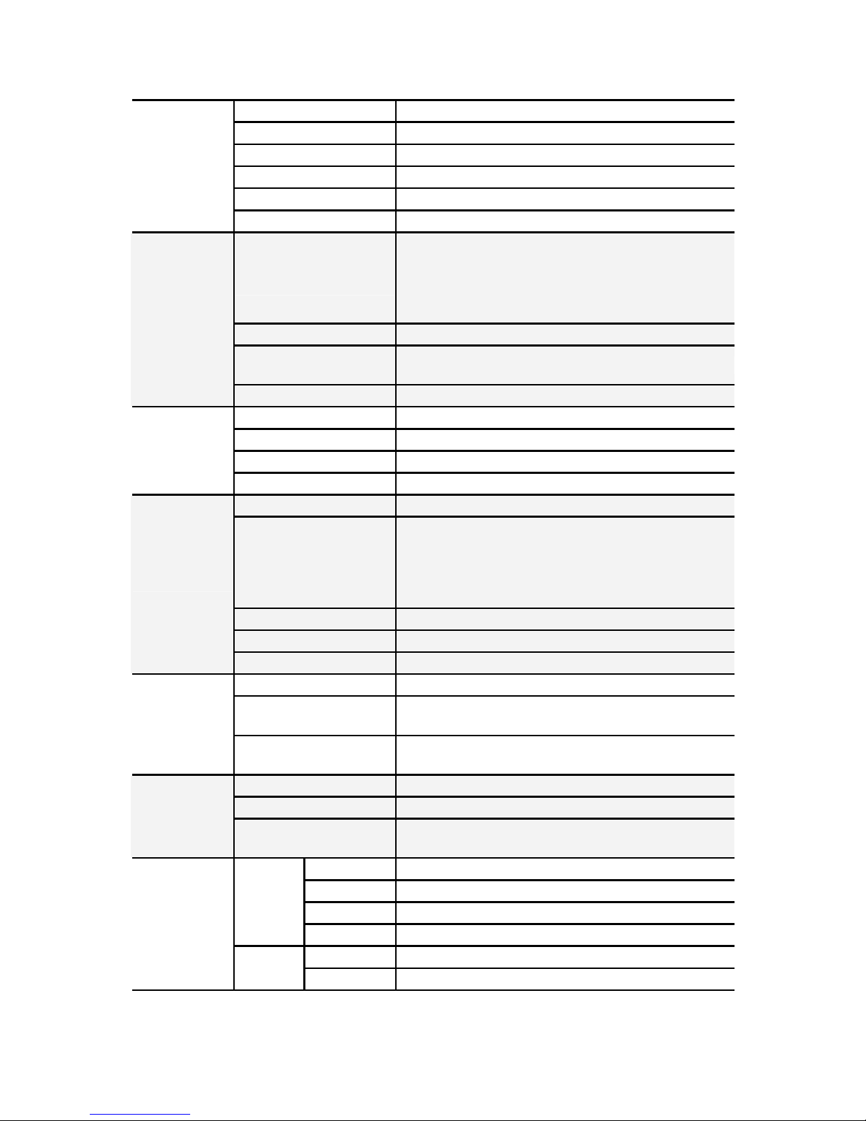
1.4.1 Box Contents
Component Description
2U chassis,(8) hot swap HDDbays
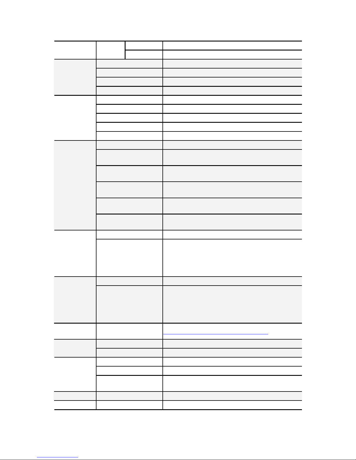
TYAN
®
Thunder S4989 system board
PCI holder
(B4989T68W8HR-LE SKU)
1 x slim ODD drive (pre-installed)
Air Duct
M1003:
LED control board
M1029 power board
10
Chapter 1: Overview
Page 19
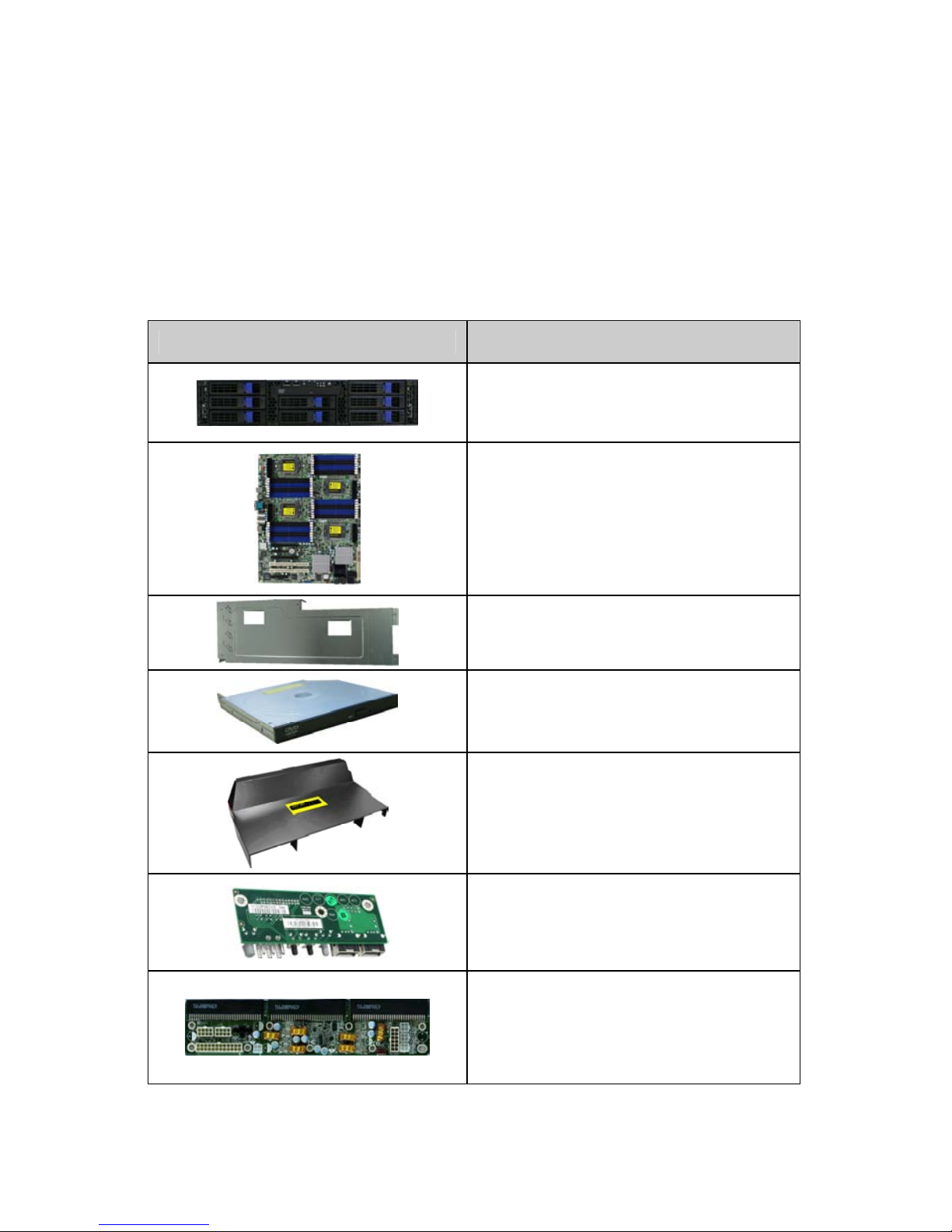
Component Description
M1229-PT HDD Backplane
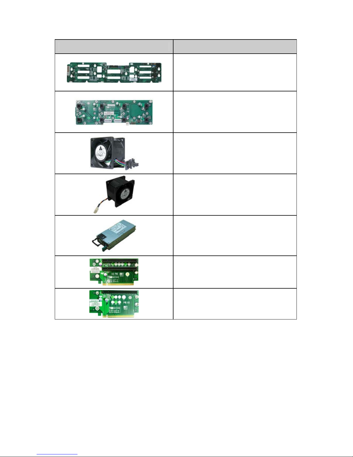
M1022 Fan BD
(8) System fans
(60mm x 60mm x 38mm)
(1) PCI-E fan
(60mm x 60mm x 38mm)
(3) 700W power supply modules
(1)PCI-Ex16 to (2)PCI-Ex8 2U Riser
Card (B4989T68W8HR-LE SKU)
PCI-Ex16 to PCI-Ex16 1U Riser Card
(B4989T68W8HR-LE SKU)
Chapter 1: Overview
11
Page 20
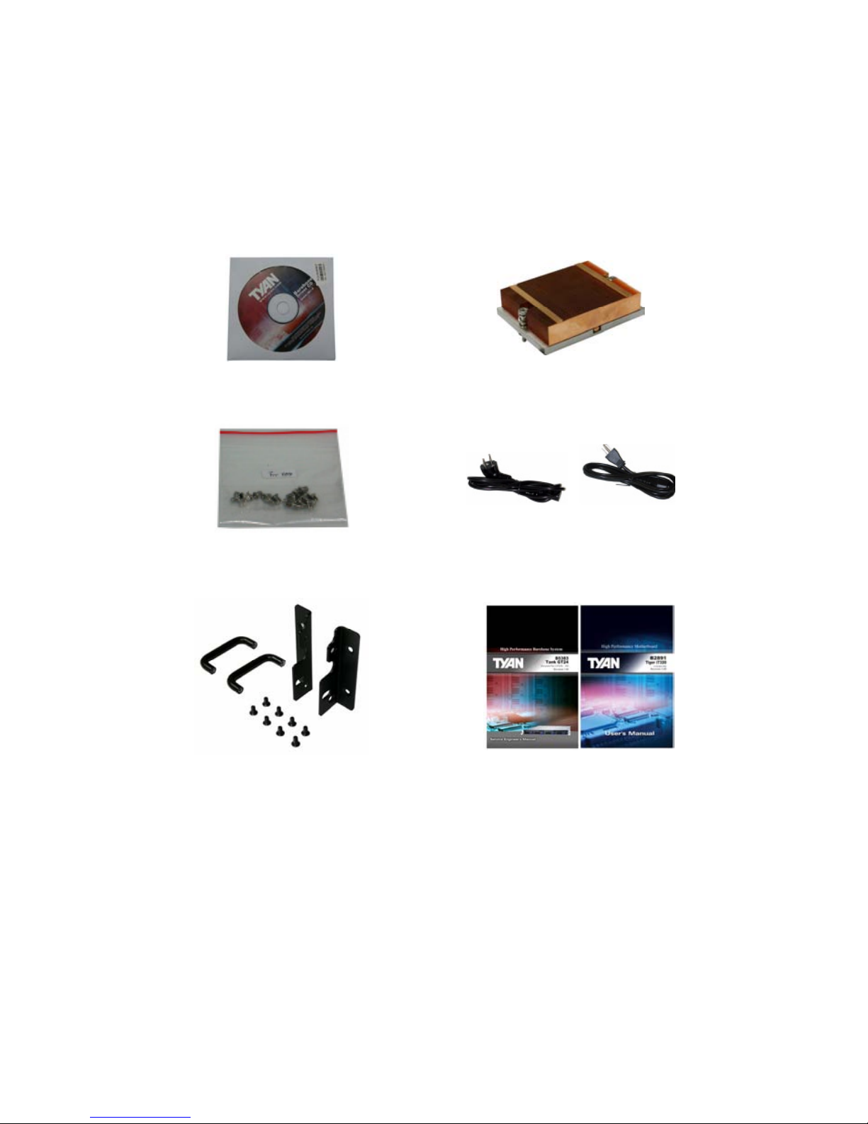
1.4.2 Accessories
If any items are missing or appear damaged, contract your retailer
or browse to TYAN
®
’s website for service: http://www.tyan.com.
The Web site also provides information on other TYAN® products,
plus FAQs, compatibility lists, BIOS settings, and more.
1 x TYAN
®
Motherboard
Drive CD
4 x Heatsink
HDD Screws
Power Cables
Left to right: Europe, US
Mounting Ears & Screws
Barebone Manual &
Mainboard Manual
12
Chapter 1: Overview
Page 21
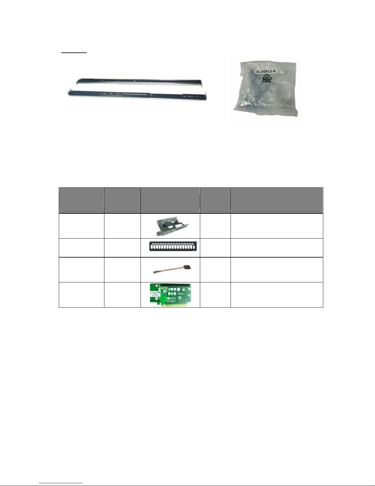
Rail Kit
Rail with Bracket x 2 Screw Sack
1.5 Optional Parts
Item
Model
Number
Picture Quantity Description
HDD Tray CHDT-0111
1 Internal 2.5" HDD Tray
DVD Dummy
Cover
CMPT-0170
1
TN68 DVD Dummy Cover
(B4989T68W8HR SKU)
Cable Set CCBL-1070
1
Internal 2.5" HDD Power
Cable,100mm
(B4989T68W8HR SKU)
M2090 Riser
Card
M2090
1
PCI-Ex16 to PCI-Ex16 1U Riser
Card (B4989T68W8HR-LE SKU)
Chapter 1: Overview
13
Page 22
1.6 About the Product
The following views show you the product.
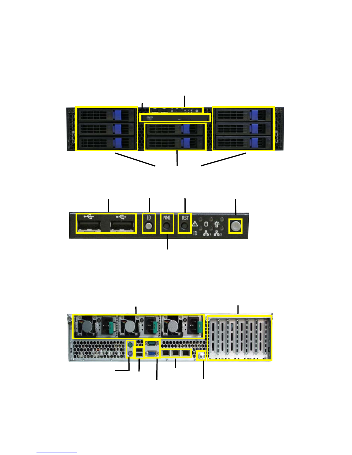
1.6.1 System Front View
LED control board
DVD-Rom drive
Hot Swap HDD bays (from HDD1 to HDD8)
USB ports ID button Reset button Power button.
NMI button
1.6.2 System Rear View
B4989T68W8HR-SI:
Redundant Power supply Expansion slots
Stacked PS/2 mouse
& keyboard ports
USB ports
RJ-45 LAN ports
1
4
7
2
5
3
6
8
Serial port & VGA port
ID LED
14
Chapter 1: Overview
Page 23
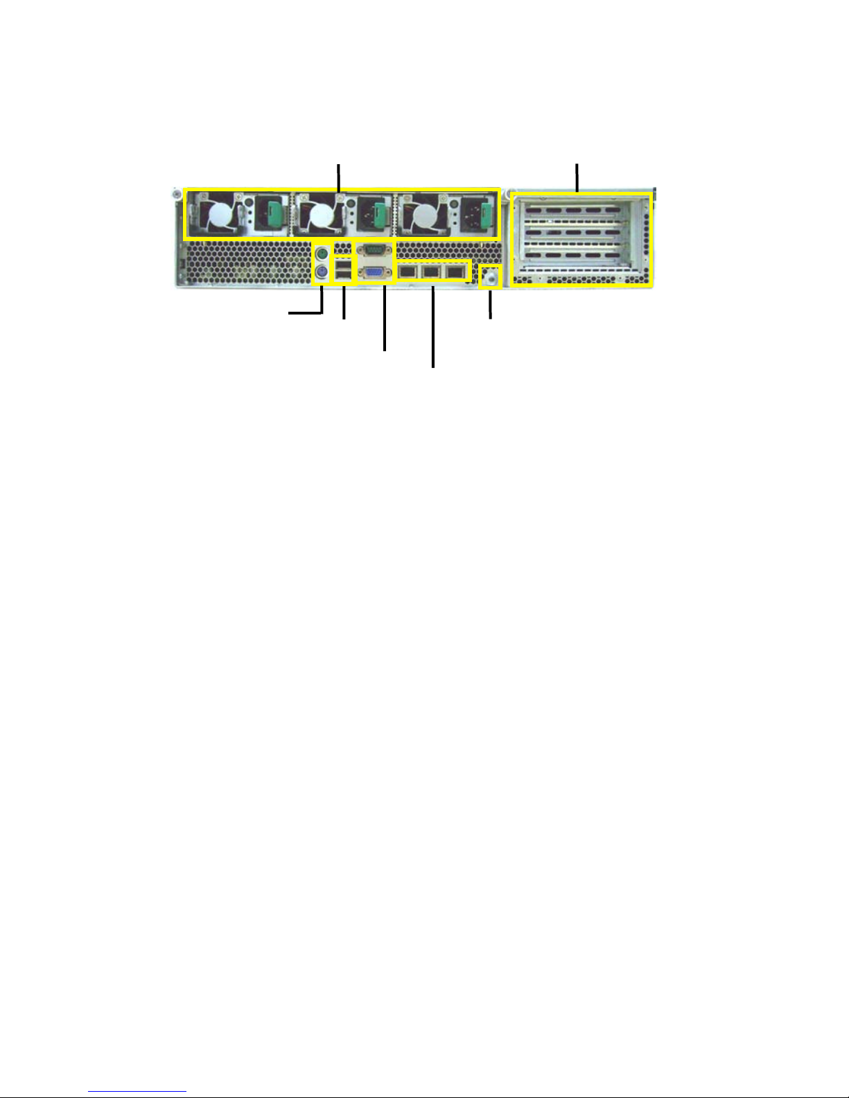
B4989T68W8HR-LE
Redundant Power Supply
Expansion slots
Stacked PS/2 mouse
& keyboard ports
USB ports
USB ports
RJ-45 LAN ports
ID LED
Chapter 1: Overview
15
Page 24
1.6.3 LED Definitions
Front Panel
LED State Color Description
On Green System is turned on
On Amber System is turned off
Power
LED
Off Off Power off
On Green HDD power on
Blinking Green HDD active
On Amber HDD error
Blinking Amber HDD rebuild
HDD LED
Random
Green/
Amber
HDD locate
Blinking Amber LAN is active
LAN LED
off off No LAN is linked
ID LED On Blue ID select on
Warning
LED
On Red
Fan fail/PSU fail/Over
temperature/Over voltage
Rear I/O LED
LED State Color Description
On Green Output On and OK
Blinking Green
AC present / Only 5Vsb on(PS
Off)
On Amber
No AC power to this PSU only
or Power supply critical event
causing a shutdown: failure,
fuse blown, OCP(12V),OVP(12
V), Fan failed
Blinking Amber
Power supply warning events
where the power supply contin-
-ues to operate: high temp,high
power / high current,slow fan.
Power supply module
Off Off
No AC power to all power suppl
-ies.
On Green 10Mb/100Mb/1000Mb linked
Blinking Green 10Mb/100Mb/1000Mb activity
RJ-45
Linkage/
Activity(left)
Off Off No LAN linked
On Amber 1000Mb linked/ activity
On Green 100Mb linked/activity
RJ-45
Linkage/
Activity(Right)
Off Off 10Mb mode or No LAN linked
16
Chapter 1: Overview
Page 25
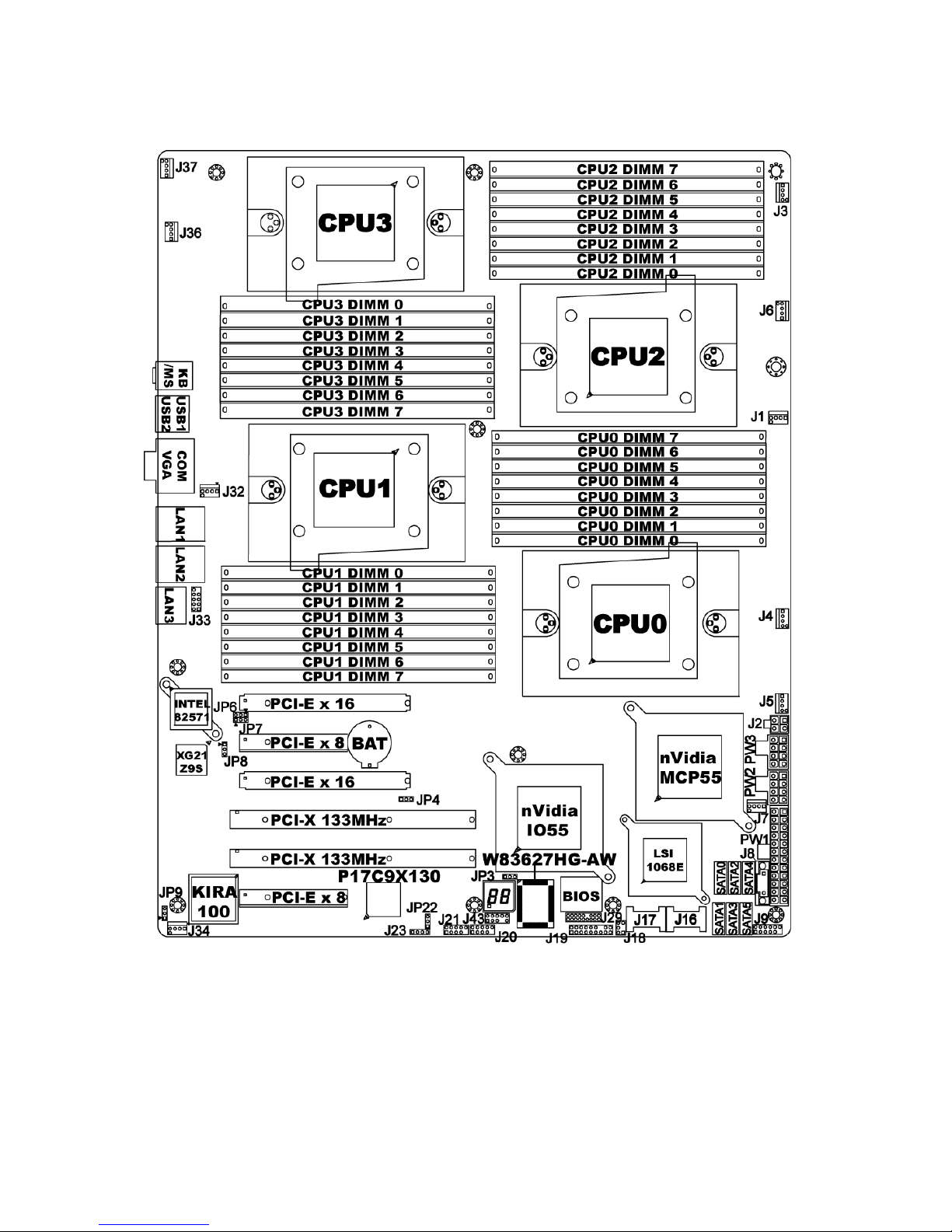
1.6.4 Motherboard (S4989WG2NR-SI) Layout
The diagram is representative of the latest board revision available at the time of
publishing. The board you receive may not look exactly like the above diagram.
Chapter 1: Overview
17
Page 26
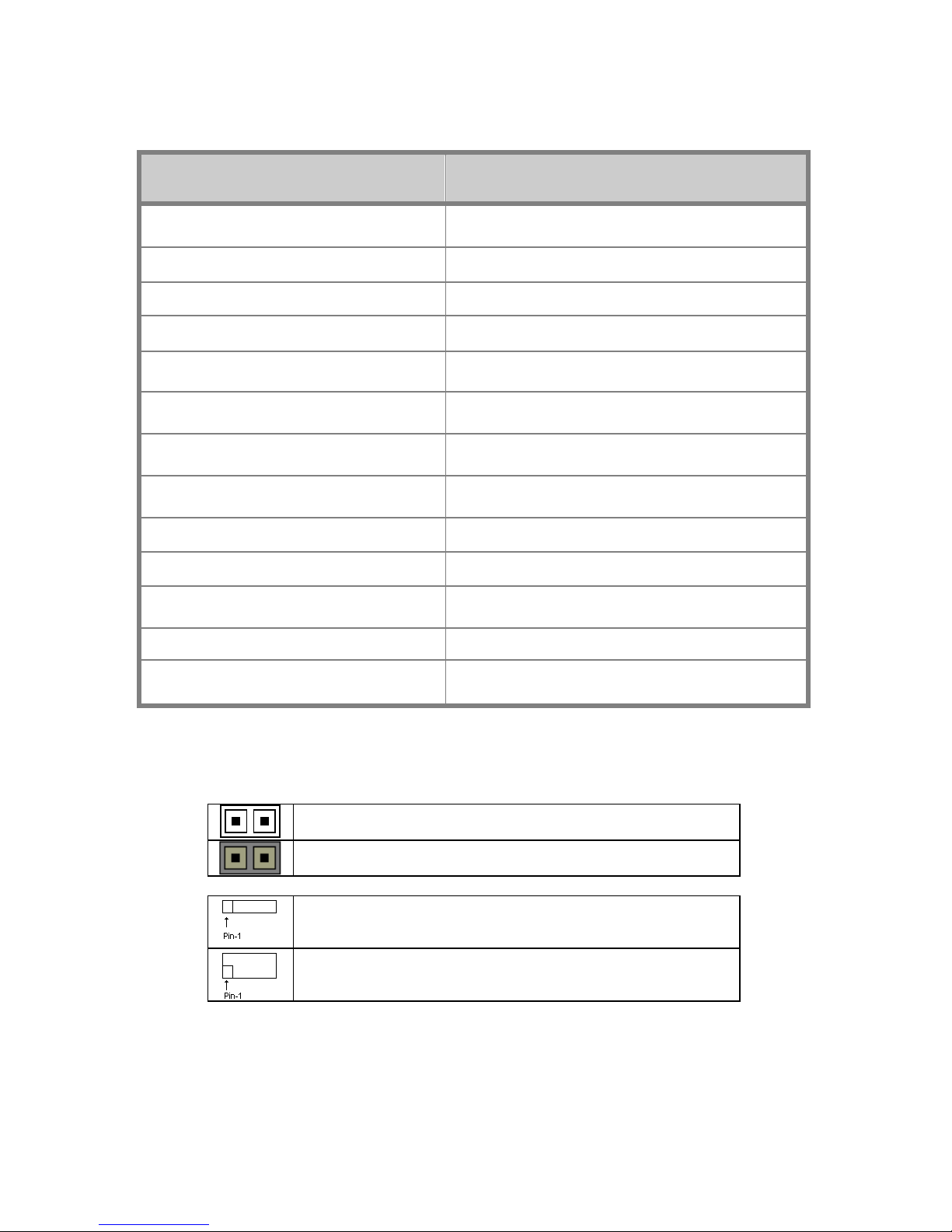
1.6.5 Jumpers & Connectors
Jumper/Connector Function
J1/J3/J4/J5/J6/J7/J32/J34/J36/J37 Fan connector
J8 PSMI header
J9 Front Panel header for Barebone System
J18 LCM header
J19 Front Panel header
J20/J21 USB 2.0 header
J23 PCI-X Speed Selection
J29 BBU Fan connector
JP3 Clear COMS
JP4 PCI-E configuration selection
JP8 XG21 VGA Enable/Disable Jumper
JP9 IPMB Pin header
JP22
PCI-X clock frequency 133/100 MHz
selection
Jumper Legend
OPEN - Jumper OFF Without jumper cover
CLOSED - Jumper ON With jumper cover
To indicate the location of pin-1
To indicate the location of pin-1
18
Chapter 1: Overview
Page 27
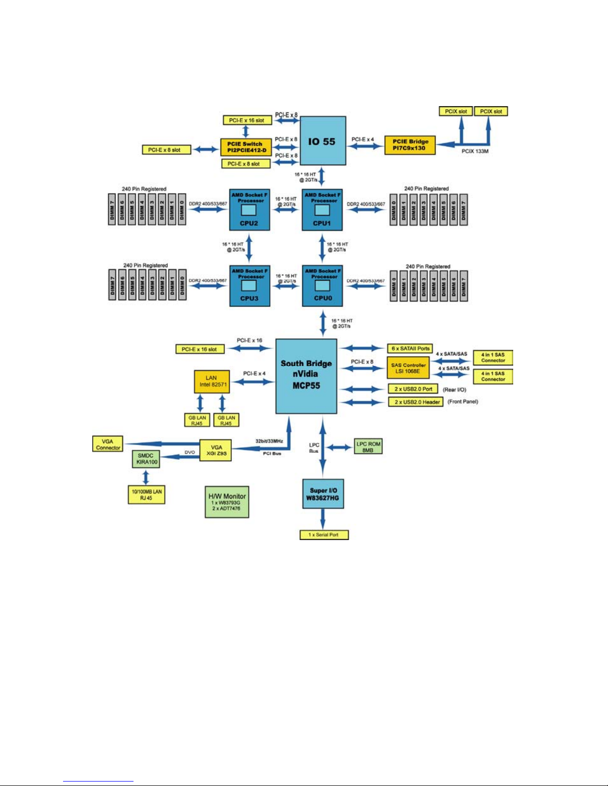
1.6.6 System Block Diagram
Chapter 1: Overview
19
Page 28
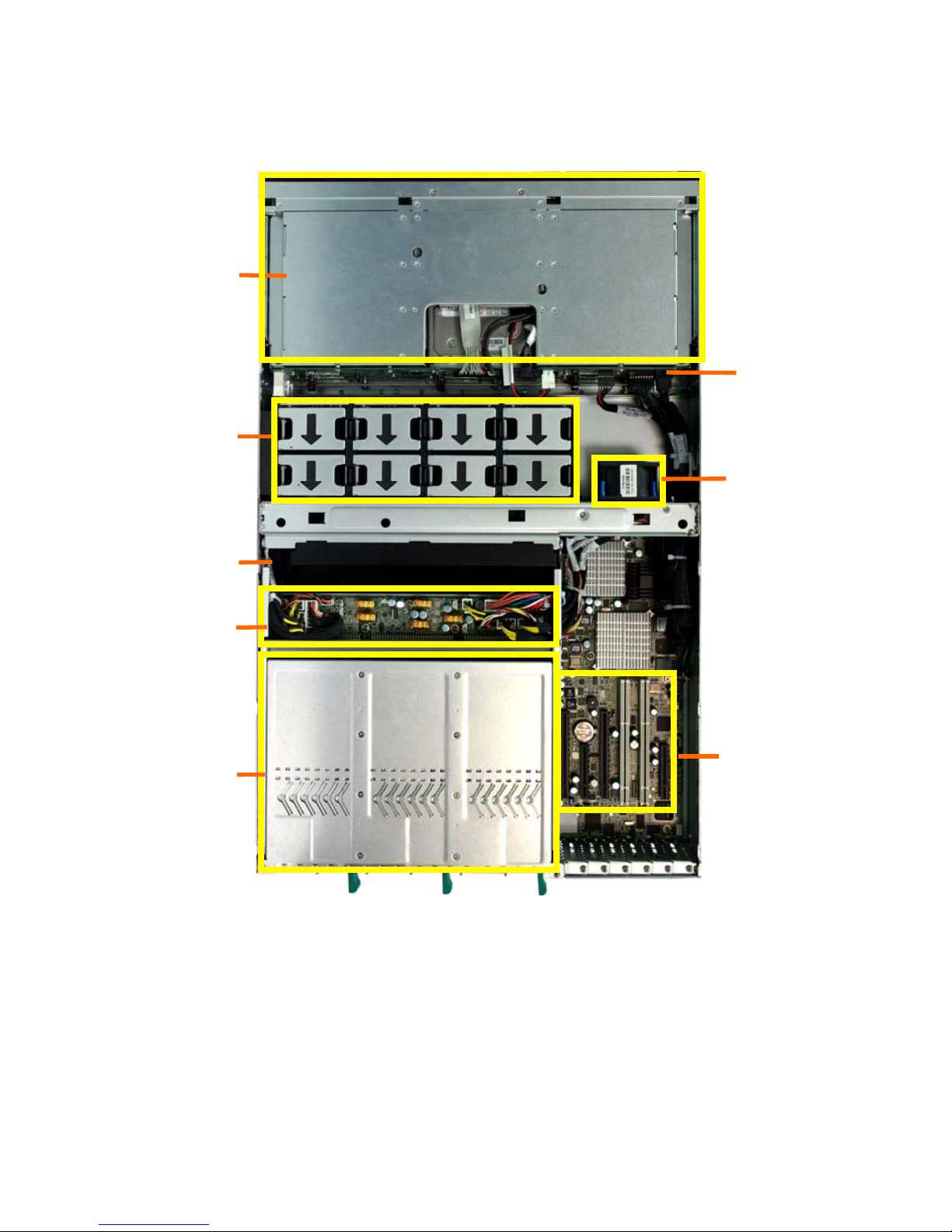
1.6.7 Internal View
B4989T68W8HR-SI:
①/⑥
System Fan
②
Air Duct
③
M1029 Power backplane
④
Power Cage
⑤
M1229-PT HDD backplane
⑦
Expansion slots
⑧
HDD Cage
1 2 3 4
9
①
②
③
④
⑤
⑥
⑦
PSU1
PSU2
PSU3
⑧
5 6 7 8
20
Chapter 1: Overview
Page 29
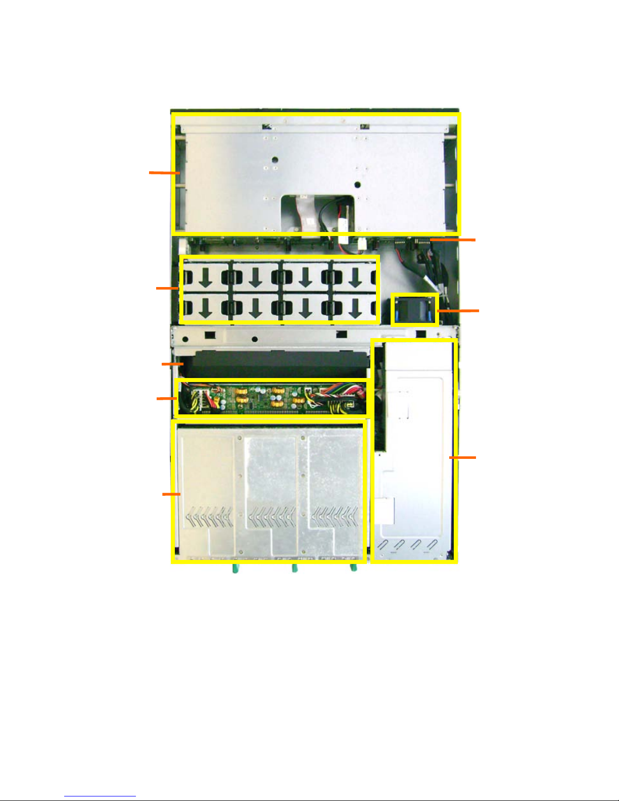
B4989T68W8HR-LE:
①/⑥
System Fan
②
Air Duct
③
M1029 Power backplane
④
Power Cage
⑤
M1229-PT HDD backplane
⑦
PCI Holder
⑧
HDD Cage
PSU1
PSU2
PSU3
⑧
⑦
④
③
②
①
⑤
⑥
5 6 7 8
1 2 3 4
9
Chapter 1: Overview
21
Page 30

22
Chapter 1: Overview
Page 31

Chapter 2: Setting Up
2.0.1 Before you Begin
This chapter explains how to install the CPUs, CPU heatsinks,
memory modules, and hard drives. Instructions on inserting add on
cards are also given.
2.0.2 Work Area
Make sure you have a stable, clean working environment. Dust and
dirt can get into components and cause malfunctions. Use
containers to keep small components separated. Putting all small
components in separate containers prevents them from becoming
lost. Adequate lighting and proper tools can prevent you from
accidentally damaging the internal components.
2.0.3 Tools
The following procedures require only a few tools, including the
following:
z A cross head (Phillips) screwdriver
z A grounding strap or an anti-static pad
Most of the electrical and mechanical connections can be disconne-
-cted using your fingers. It is recommended that you do not use nee-
-dlenosed pliers to remove connectors as these can damage the soft
metal or plastic parts of the connectors.
Chapter 2: Setting Up
23
Page 32

2.0.4 Precautions
Components and electronic circuit boards can be damaged by
discharges of static electricity. Working on a system that is connected
to a power supply can be extremely dangerous. Follow the guidelines
below to avoid damage to the Transport TN68-B4989 or injury to
yourself.
z Ground yourself properly before removing the top cover of the
system. Unplug the power from the power supply and then
touch a safely grounded object to release static charge (i.e.
power supply case). If available, wear a grounded wrist strap.
Alternatively, discharge any static electricity by touching the
bare metal chassis of the unit case, or the bare metal body of
any other grounded appliance.
z Avoid touching motherboard components, IC chips, connectors,
memory modules, and leads.
z The motherboard is pre-installed in the system. When
removing the motherboard, always place it on a grounded
anti-static surface until you are ready to reinstall it.
z Hold electronic circuit boards by the edges only. Do not touch
the components on the board unless it is necessary to do so.
Do not flex or stress circuit boards.
z Leave all components inside the static-proof packaging that
they ship with until they are ready for installation.
z After replacing optional devices, make sure all screws, springs,
or other small parts are in place and are not left loose inside
the case. Metallic parts or metal flakes can cause electrical
shorts.
Note:
All connectors are keyed to only attach one way.
All use the correct screw size as indicated in the procedures.
24
Chapter 2: Setting Up
Page 33

2.1 Installing Motherboard Components
This section describes how to install components on to the motherboa-
-rd, including CPUs, memory modules and add on cards.
2.1.1 Removing the Chassis Cover
Follow these instructions to remove the Transport TN68 chassis cover.
1. Thumb two screws on the back side as shown in the small
diagram. Then slide the rear top cover out.
2.
Draw the two buttons on the front top cover in the direction as the
following photo shows and remove the top cover.
Chapter 2: Setting Up
25
Page 34

2.1.2 Installing the CPU and Heatsink
Follow the steps below on installing CPUs and CPU heatsinks.
1. Pull out the three power supplies: press the button on top of the
power supply and pull out the supply in the direction the arrow shows
you.
2. Unscrew the power cage as the image shows you;
26
Chapter 2: Setting Up
Page 35

3. Lift the rack of the power cage and bend it back to an angle of about
140
°;
4. Pull out the pre-installed air duct so you will locate the CPU sockets,
the following images show in details.
A
Chapter 2: Setting Up
27
Page 36

B
Note:
The system supports up to four CPUs, CPU0 must be
installed first follow by CPU1, CPU2 and CPU3. For CPU
sequence please refer to Chapter 1.5.3.
5. Take off the CPU
protection cap;
6. Lift up the CPU lever to
unlock the socket, Open
the socket cover as the
arrow shows;
28
Chapter 2: Setting Up
Page 37

7
. Place the CPU in the
socket, ensuring that
pin1 is correctly
located;
8. Closer the socket cover
and press the CPU lever
down to secure the CPU;
9. Place the heatsink on
top of the CPU and
screw it as below;
Chapter 2: Setting Up
29
Page 38

2.1.3 Installing the Memory
Follow these instructions to install the memory modules on the
motherboard. Your TN68-B4989 boasts up to 32 DIMM sockets.
1. Press the memory slot locking levers in the direction of the
arrows as shown in the following illustration.
2. Align the memory module with the slot. When inserted
properly, the memory slot locking levers lock automatically
onto the indentations at the ends of the module.
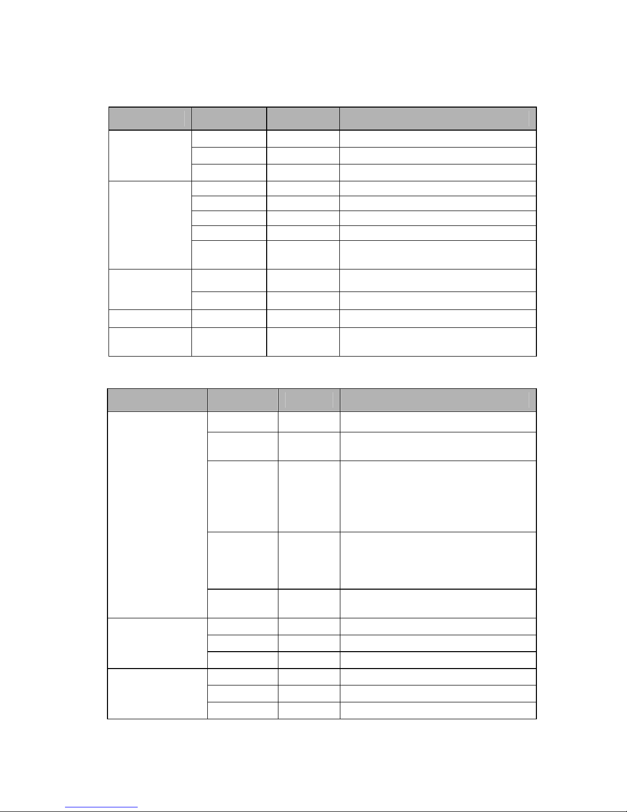
NOTE: For optimal system operation, please install memory in pairs.
Memory Population Option Table
To correctly install the memory in pairs, please refer to the table on the
next page for supported population options. Start installing memory
modules from DIMM6 and DIMM7.
30
Chapter 2: Setting Up
Page 39

CPU
DIMM
Single
(CPU0)
Dual
(CPU0 and1)
Four
(CPU0,1,2 and3)
Quantity of
memory
installed
2 4 8 4 8 16 8 16 32
CPU0_DIMM0
√
√
√
CPU0_DIMM1
√
√
√
CPU0_DIMM2
√
√
√
CPU0_DIMM3
√
√
√
CPU0_DIMM4
√ √
√ √
√ √
CPU0_DIMM5
√ √
√ √
√ √
CPU0_DIMM6
√ √ √ √ √ √ √ √ √
CPU0_DIMM7
√ √ √ √ √ √ √ √ √
CPU1_DIMM0
√
√
CPU1_DIMM1
√
√
CPU1_DIMM2
√
√
CPU1_DIMM3
√
√
CPU1_DIMM4
√ √
√ √
CPU1_DIMM5
√ √
√ √
CPU1_DIMM6
√ √ √ √ √ √
CPU1_DIMM7
√ √ √ √ √ √
CPU2_DIMM0
√
CPU2_DIMM1
√
CPU2_DIMM2
√
CPU2_DIMM3
√
CPU2_DIMM4
√ √
CPU2_DIMM5
√ √
CPU2_DIMM6
√ √ √
CPU2_DIMM7
√ √ √
CPU3_DIMM0
√
CPU3_DIMM1
√
CPU3_DIMM2
√
CPU3_DIMM3
√
CPU3_DIMM4
√ √
CPU3_DIMM5
√ √
CPU3_DIMM6
√ √ √
CPU3_DIMM7
√ √ √
Chapter 2: Setting Up
31
Page 40

2.1.4 Installing Expansion Cards
2.1.4.1 B4989T68W8HR-SI
B4989T68W8HR-SI has six expansion slots:
2 × PCI-E×16 slots
2 × PCI-E×4 slots
2 × PCI-X 133MHz slots
Follow these instructions to install any of the above kinds of
expansion cards.
1. Locate the expansion slot on the motherboard, unscrew the
bracket from the slot you want to use.
2. Take the bracket out from
the slot in the direction of
the arrow shows.
3. Insert the card into the slot
and secure it with the screw
you removed from the
bracket.
32
Chapter 2: Setting Up
Page 41

Chapter 2: Setting Up
33
Page 42

2.1.4.2 B4989T68W8HR-LE
1.Unscrew the PCI holder and lift the holder up from the chassis.
2. Turn over the PCI holder and unscrew the bracket from the
holder.
3. Insert the PCI-E card into the slot and secure it to the holder.
4. Replace the PCI holder to the chassis, make sure that the
holder is correctly inserted into the socket as the images shows
you.
34
Chapter 2: Setting Up
Page 43

5. Secure the holder to the chassis follow the above steps in
reverse.
Chapter 2: Setting Up
35
Page 44

2.1.5 Installing Hard Drives
The TN68-B4989 supports eight 3.5” hard drives. Follow these
instructions to install a hard drive.
1. Press the locking lever latch and pull the locking lever open.
2. Slide the HDD tray out.
3. Place a hard drive into the HDD tray.
36
Chapter 2: Setting Up
Page 45

4. Turn over the HDD unit and secure the HDD using 4 HDD
screws.
5. Reinsert the HDD tray into the chassis and press the locking
lever to secure the tray.
Chapter 2: Setting Up
37
Page 46

2.2 Rack Mounting
After installing the necessary components, the Transport TN68-B49
-89 can be mounted in a rack using the supplied rack mounting kit.
Rack mounting kit
Rail with Bracket x 2
Mounting Ears x 2
Screw Sack x 1
2.2.1 Installing the Server in a Rack
Follow these instructions to mount the TN68-B4989 into an industry
standard 19” rack.
Note:
Before mounting the Transport TN68-B4989 in a rack,
ensure that all internal components have been installed and
that the unit has been fully tested. Maintenance can be
performed on the unit while in a rack but it is preferable to
install the device in a fully operational condition.
Screw Sack
A B C
Including
A: M4 x 5 x P0.7----10pcs
B: M6 x 13 -----------10pcs
C: M6 ------------------10pcs
38
Chapter 2: Setting Up
Page 47

2.2.2 Installing the inner Rails to the Chassis
1. Screw the mounting ear to each side of TN68 as shown using 2
screws from the supplied screws kit.
2. Push the latch key and draw out the inner rails from sliding rails.
3. Install inner rails to left and right sides of chassis using 3 M4 x 5 x
P0.7 (A) screws for each side.
Chapter 2: Setting Up
39
Page 48

2.2.3 Installing the Outer Rails to the Rack
Secure the outer rail to the rack using the rail and 4 M4 x 5 x P0.7 (A)
screws for each side (A). Secure the mounting brackets from inside,
not outside, of the rack (B).
A B
2.2.4 Rack mounting the Server
1. Draw out the middle rail to
the latch position.
2. Lift the chassis and then
insert the inner slide rails
into the middle rails.
40
Chapter 2: Setting Up
Page 49

3. Push the chassis in and pull the latch key (A). Then push the whole
system into the rack (B).
A B
4. Secure the mounting
ears of chassis to the
rack with 2 M6 x 13 (B)
screws.
Note:
To avoid injury, it is strongly recommended that two people
lift the TN68-B4989 into the place while a third person
screws it to the rack.
Chapter 2: Setting Up
41
Page 50

42
Chapter 2: Setting Up
Page 51

Chapter 3: Replacing Pre-Installed
Components
3.1 Introduction
This chapter explains how to replace the pre-installed components,
including the Motherboard, M1003 LED control board, M1229-PT
HDD backplane, M1022 FAN board, System fan, ODD drive, Power
supply unit etc..
3.2 Disassembly Flowchart
The following flowchart outlines the disassembly procedure.
Rear Components
Chassis rear cover
Power cage
Mainboard
Air duct
DIMMs
CPU/Heatsink Assembly
PCI Card
Mainboard
Chapter 3: Replacing Preinstalled Components
43
Page 52

Front Components
Chassis rear cover
ODD
PCBs
FAN
M1003 LED
Control Board
M1229-PT HDD
Backplane
M1022
FAN Board
M1029 power
board
44
Chapter 3: Replacing Preinstalled Components
Page 53

3.3 Removing the Cover
Before replacing any parts you must remove the chassis cover.
Follow Chapter 2.1.1 to remove the cover of the Transport TN68-
-B4989.
3.4 Replacing Motherboard Components
Follow these instructions to replace motherboard components,
including the motherboard.
3.4.1 Disconnecting All Motherboard Cables
Before replacing the motherboard or certain components, remove
cables connected to the motherboard. Follow these instructions to
remove all motherboard cabling.
1. Disconnect all the power cable
2. Disconnect SATA/SAS cable, DVD Rom drive cable, USB cable
and front panel cable.
.
Chapter 3: Replacing Preinstalled Components
45
Page 54

46
Chapter 3: Replacing Preinstalled Components
Page 55

3.4.2 Removing the Motherboard
After removing all of the aforementioned cables, follow these
instructions to remove the motherboard from the chassis.
1. Remove the heatsinks and processors if installed.
2. Remove the eleven screws securing the motherboard to the
chassis.
Note: You may need to unscrew the front three screws through the
holes in the bracket.
Chapter 3: Replacing Preinstalled Components
47
Page 56

3. Carefully lift the motherboard from the chassis as the image
shows you.
Note:
The motherboard is too large to lift straight out .Lift the front
edge of the board to an angle of about 45 then slides the
whole board out.
48
Chapter 3: Replacing Preinstalled Components
Page 57

3.5 Replacing the Slim DVD-ROM
Follow these instructions to replace the DVD-ROM.
1. Remove the cables from the HDD backplane.
2. Push the stopper in the direction as the arrow shows.
3. Push the DVD through the front of the TN68-B4989.
Chapter 3: Replacing Preinstalled Components
49
Page 58

4. Replace the DVD.
5. Connect the DVD to the backplane follow the above steps in
reverse.
50
Chapter 3: Replacing Preinstalled Components
Page 59

3.6 Replacing the LED Control Board
Follow these instructions to replace the M1003 LED control board.
1. Remove the two screws securing the LED control board unit to
the chassis.
2. Unplug the cables from the connectors on the HDD backplane.
3. Push the LED control board unit out.
(Note: You may need a screwdriver to push the board at the
rear side.)
Chapter 3: Replacing Preinstalled Components
51
Page 60

4. Remove three screws securing the LED control board to the
bracket.
5. Lift the LED control board free from the chassis. After replacem-
-ent, insert the unit into the chassis following the above proced-
-ures in reverse.
52
Chapter 3: Replacing Preinstalled Components
Page 61

3.6.1 M1003 LED Control Board Features
3.6.2 M1003 LED Control Board Connector Pin Definition
J2 Front Panel Connector:
Definition Pin Pin Definition
HDLED+
1 2
HDLED-
RESET+
3 4
RESET-
PW_LED+
5 6
PW_LED-
WLED+
7 8
WLED-
OCJ_SMBDAT
9 10
ICH_SMBCLK
EXT_INT
11 12
VOLTAGE5
V5SB
13 14
INTRU#
PWR_SW+
15 16
PWR_SW-
LAN1_LED+
17 18
LAN1_LED-
LAN2_LED+
19 20
LAN2_LED-
Reserve
21 22
Reserve
ID_LED+
23 24
ID_LED-
ID_SW+
25 26
ID_SW-
KEY PIN
68 28
NC
Chapter 3: Replacing Preinstalled Components
53
Page 62

J1 USB Connector:
Definition Pin Pin Definition
VCC5
1 2
VCC5
USB1-
3 4
USB0-
USB1+
5 6
USB0+
GND
7 8
GND
KEY PIN
9 10
GND
54
Chapter 3: Replacing Preinstalled Components
Page 63

3.7 Replacing the System Fan
1. Press the button in the arrow direction and lift out the fan
needing replacing.
A
B
2. Remove two screws on one side (A) and one screw on the
other side of the fan bracket (B).
A B
3. Open the fan bracket and move the connector of the fan in the
arrow’s direction.
Chapter 3: Replacing Preinstalled Components
55
Page 64

4. Install a new fan into the bracket.
5. Place the FAN unit into the FAN holder
6.
Reinsert the fan holder into the chassis and fix it with four screws.
56
Chapter 3: Replacing Preinstalled Components
Page 65

3.8 Replacing the M1022 Fan Board
1. Disconnect all cables connected to the Fan board.
2. Remove screws to release the system fan holder. And lift
the system fan holder out.
3. Release all system fans from the fan holder (Refer to 3.7.1)
4. Turn over the system fan holder to remove fourteen screws
securing the M1022 Fan Board.
Chapter 3: Replacing Preinstalled Components
57
Page 66

5. Secure a new M1022 Fan Board to the fan holder and install the
whole unit into the chassis following the above steps in reverse.
58
Chapter 3: Replacing Preinstalled Components
Page 67

3.8.1 M1022 Fan Board Features
J1: Fan 8 Connector
J9:
Fan Tach. Header
PW1
J3: Fan 7 Connector
J5: Fan 6 Connector
J7: Fan 5 Connector
J2: Fan 4 Connector
J4: Fan 3 Connector
J6: Fan 2 Connector
J8: Fan 1 Connector
PW2
J10: Power Connector
Chapter 3: Replacing Preinstalled Components
59
Page 68

3.8.2 M1022 Fan Board Connector Pin Definition
J1~J8: Hot-swapped Fan Connectors (2Pin x 2)
Definition Pin Pin Definition
POWER
1 2
FAN_PWM
GND
3 4
FAN_TACH
J9: Fan Tach.Header (9Pin x 2)
Definition Pin Pin Definition
FAN1_TACH
1 2
FAN6_TACH
FAN2_TACH
3 4
FAN7_TACH
FAN2_TACH
5 6
FAN8_TACH
FAN4_TACH
7 8
FAN_PWM5
FAN5_TACH
9 10
FAN_PWM4
GND
11 12
KEY PIN
GND
13 14
FAN_PWM3
HWM_SMBUSC_2
15 16
HWM_INT_1
HWM_SMBUSD_2
17 18
FAN_PWM6
J10: Power Connector (4Pin x 1)
Pin 1 2 3 4
Definition
3.3V GND GND 3.3V
PW1 & PW2 connectors (4Pin x 1)
Pin 1 2 3 4
Definition
+12V GND GND +12V
60
Chapter 3: Replacing Preinstalled Components
Page 69

3.9 Replacing the M1229-PT HDD Backplane
Step 1: Disconnect all cables connected to M1229-PT HDD
backplane.
①. ②.
③.
④.
Chapter 3: Replacing Preinstalled Components
61
Page 70

Step 2: Remove the two screws securing M1229-PT HDD
backplane to the chassis base.
Step 3: Lift the M1229-PT HDD backplane kit from the chassis.
Step 4: Replace a new M1229-PT HDD Backplane and reinstall it
into the chassis following the above steps in reverse.
62
Chapter 3: Replacing Preinstalled Components
Page 71

3.9.1 M1229-PT HDD Backplane Features
Front View:
J20
J11
J18
PW3
PW1
J41
JP1
J12
J8: Mini SAS
J3: Mini SAS
J16
J19
J13
J21
J15
Chapter 3: Replacing Preinstalled Components
63
Page 72

Rear View:
64
Chapter 3: Replacing Preinstalled Components
Page 73

3.9.2 M1229-PT HDD Backplane Connector Pin Definitions
Input Power Connectors:
PW3:
SIGNAL PIN PIN SIGNAL
GND
1 2
+12V
GND
3 4
+12V
GND
5 6
+12V
GND
7 8
+5V
GND
9 10
+5V
GND
11 12
+3.3V
PW1:
SIGNAL PIN PIN SIGNAL
GND
1 2
+12V
GND
3 4
+12V
J18: 4P DVD-ROM:
PIN 1 2 3 4
SIGNAL
+12V GND GND +5V
J41: CPLD Header:
SIGNAL PIN PIN SIGNAL
CPLD_JTAG_TCK
1 6
NC
GND
2 7
NC
CPLD_JTAG_TDO
3 8
NULL
VCC-
4 9
CPLD_JTAG_TDI
CPLD_JTAG_YMS
5 10
GND
J12/J13: USB Header:
SIGNAL PIN PIN SIGNAL
VDD_5_RUN
1 6
USB0+
VDD_5_RUN
2 7
GND
USB1-
3 8
GND
USB0-
4 9
DIE
USB1+
5 10
GND
J20/J21: DVD/SATA Connector:
SIGNAL PIN PIN SIGNAL
GND
1 6
SATA_DVD_RXP1
SATA_DVD_TXP1
2 7
GND
SATA_DVD_TXN1
3 G1
GND
GND-
4 G2
GND
SATA_DVD_RXN1
5
Chapter 3: Replacing Preinstalled Components
65
Page 74

J11: Front panel Header:
SIGNAL PIN PIN SIGNAL
NC
1 2
NC
ID_SW-
3 4
GND ID_SW+
ID_LED-
5 6
ID_LED+
NC
7 8
NC
LAN2_LED-
9 10
LAN2_LED+
LAN1_LED-
11 12
LAN1_LED+
PWR_SW-
13 14
PWR_SW+
NC
15 16
NC
VOLTAGE5
17 18
EXT_INT
NC
19 20
NC
WLED-
21 22
WLED+
PW_LED-
23 24
PW_LED+
RESET-
25 26
RESET+
HDLED-
27 28
HDLED+
JP1:
Pin_ 3 Pin_1
Default; SAS\SATA port0 connect
with mini sas connector
Pin_3 Pin_1
SAS\SATA port0 connect with sata
port of motherboard
66
Chapter 3: Replacing Preinstalled Components
Page 75

3.10 Replacing the Power Supply
3.10.1 Replace the power supply
To replace the power supply follow these instructions.
1. Press the tab as shown in the diagram and pull out the power.
2. Free the power from the power socket.
You can refer to Chapter 2.1.2 for the above steps.
3. Replace a new single power (FRU NO.: CPSU-0350) and
reinsert it into the power socket following the above steps in
reverse.
3.10.2 Replace the power board M1029
1. Disconnect all the cables connect to M1029.
Chapter 3: Replacing Preinstalled Components
67
Page 76

2. Remove the 9 screws securing M1029 power board to the
chassis base.
3. Renew the M1029 and fix it to the chassis following the steps in
reverse.
68
Chapter 3: Replacing Preinstalled Components
Page 77

3.10.3 M1029 power board Features
PW9
PW10
PW11
PW12
PW4
PW7
PW8
J2
J1
PW6
PW1
PW2
PW3
Chapter 3: Replacing Preinstalled Components
69
Page 78

M1029 power board Connector Pin Definitions:
PW4:
SIGNAL PIN PIN SIGNAL
+3.3V
1 13
+3.3V
+3.3V
2 14
﹣12V
GND
3 15
GND
+5V
4 16
PS_ON
GND
5 17
GND
+5V
6 18
GND
GND
7 19
GND
PWRGD
8 20
Reserve
5VSB
9 21
+5V
+12V
10 22
+5V
+12V
11 23
+5V
+3.3V
12 24
GND
PW7 / PW8:
SIGNAL PIN PIN SIGNAL
GND
1 5
+12V
GND
2 6
+12V
GND
3 7
+12V
GND
4 8
+12V
PW 6 / 9 / 10 /12:
SIGNAL PIN PIN SIGNAL
GND
1 3
+12V
GND
2 4
+12V
PW11:
SIGNAL PIN PIN SIGNAL
GND
1 7
+12V
GND
2 8
+12V
GND
3 9
+12V
GND
4 10
+5V
GND
5 11
+5V
GND
6 12
+3.3V
J2:
PIN 1 2 3 4
SIGNAL
+3.3V GND GND +3.3V
J1:
PIN 1 2 3 4 5
SIGNAL
SMBCLK SMBDAT RSVD GND +3.3V
70
Chapter 3: Replacing Preinstalled Components
Page 79

Appendix I: BIOS Differences
The BIOS of B4989 is similar to S4989 while there are some differences in
menus. The following table displays those differences in details. For a complete
view of S4989 BIOS, please refer to the motherboard manual.
1. BIOS Version information
S4989:
BIOS Setup Utility
Main Advanced PCI/PnP Boot Security Chipset Exit
System Overview
AMIBIOS
Version : VX.XX
Build Date : DD/MM/YY
ID : 0AAAA000
Processor
Quad-Core AMD Optero(tm) Processor XXXX
Speed : xxxx MHz
Count : x
System Memory
Size : xxxx MB
System Time
[HH:MM:SS]
System Date
[MM:DD:YYYY]
Use [ENTER], [TAB] or
[SHIFT-TAB] to select a
field
Use [+] or [-] to configure
system time.
← → Select Screen
↑↓ Select Item
Enter Go to Sub Screen
F1 General Help
F10 Save and Exit
ESC Exit
Appendix I: BIOS Differences
71
Page 80

B4989:
BIOS Setup Utility
Main Advanced PCI/PnP Boot Security Chipset Exit
System Overview
AMIBIOS
Version : VX.XX.B20
Build Date : DD/MM/YY
ID : 0AAAA000
Processor
Quad-Core AMD Optero(tm) Processor XXXX
Speed : xxxx MHz
Count : x
System Memory
Size : xxxx MB
System Time
[HH:MM:SS]
System Date
[MM:DD:YYYY]
Use [ENTER], [TAB] or
[SHIFT-TAB] to select
a field
Use [+] or [-] to
configure system time.
← → Select Screen
↑↓ Select Item
Enter Go to Sub
Screen
F1 General Help
F10 Save and Exit
ESC Exit
2. FAN Configuration Sub-Menu
S4989:
BIOS Setup Utility
Main Advanced PCI/PnP Boot Security Chipset Exit
Fan Configuration
CPU FAN0 XXXXX RPM
CPU FAN1 XXXXX RPM
CPU FAN2 XXXXX RPM
CPU FAN3 XXXXX RPM
FAN1 XXXXX RPM
← → Select Screen
↑↓ Select Item
+/- Change Option
Tab Select Field
F1 General Help
F10 Save and Exit
ESC Exit
72
Appendix I: BIOS Differences
Page 81

B4989:
3. APM Configuration
S4989:
BIOS Setup Utility
Main Advanced PCI/PnP Boot Security Chipset Exit
Fan Configuration
FAN1
FAN2
FAN3
FAN4
FAN5
FAN6
FAN7
FAN8
FAN9
XXXX RPM
XXXX RPM
XXXX RPM
XXXX RPM
XXXX RPM
XXXX RPM
XXXX RPM
XXXX RPM
XXXX RPM
← → Select Screen
↑↓ Select Item
+/- Change Option
Tab Select Field
F1 General Help
F10 Save and Exit
ESC Exit
BIOS Setup Utility
Main Advanced PCI/PnP Boot Security Chipset Exit
Power Management/APM [Enabled]
Power Button Mode [On/Off]
Video Power Down Mode [Enabled]
Green PC Monitor Power State [Standby]
Hard Disk Power Down Mode [Enabled]
Hard Disk Time Out (Minute) [Disabled]
Force Throttle [Disabled]
Manual Throttle Ratio [50%]
System Thermal [Disabled]
Thermal throttle Ratio [50%]
Resume On PME# [Disabled]
Resume On PCIE Wake# [Disabled]
Resume On LAN (MAC) [Disabled]
Resume On RTC Alarm [Disabled]
Enable or Disable APM
← → Select Screen
↑↓ Select Item
+/- Change Option
Tab Select Field
F1 General Help
F10 Save and Exit
ESC Exit
Appendix I: BIOS Differences
73
Page 82

B4989:
Table of Differences
B4989 S4989
Version
VX.XX.B20 VX.XX
FAN
FAN1
FAN2
FAN3
FAN4
FAN5
FAN6
FAN7
FAN8
FAN9
CPU FAN0
CPU FAN1
CPU FAN2
CPU FAN3
FAN1
APM
/ Resume On LAN (MAC)
BIOS Setup Utility
Main Advanced PCI/PnP Boot Security Chipset Exit
Power Management/APM [Enabled]
Power Button Mode [On/Off]
Video Power Down Mode [Enabled]
Green PC Monitor Power State [Standby]
Hard Disk Power Down Mode [Enabled]
Hard Disk Time Out (Minute) [Disabled]
Force Throttle [Disabled]
Manual Throttle Ratio [50%]
System Thermal [Disabled]
Thermal throttle Ratio [50%]
Resume On PME# [Disabled]
Resume On PCIE Wake# [Disabled]
Resume On RTC Alarm [Disabled]
Enable or Disable APM
← → Select Screen
↑↓ Select Item
+/- Change Option
Tab Select Field
F1 General Help
F10 Save and Exit
ESC Exit
74
Appendix I: BIOS Differences
Page 83

Appendix II: Installing the Internal 2.5”HDD
Considering for a multiple choice, the slim DVD-ROM could be
replaced by an internal 2.5” SATA HDD in your TN68-B4989. You
can choose flexibly in practical application. The internal 2.5”HDD
from SATA port has no interference with the other eight 3.5”HDDs
from SAS port.
Step 1: Follow the instructions in Chapter 3.5 to remove the pre-
-installed slim DVD-ROM;
Step 2: Insert the internal 2.5”HDD bay into the 2.5”HDD cage thro-
-ugh the front panel;
Appendix II: Installing the Internal 2.5" HDD
75
Page 84

Step 3: Fix the 2.5”HDD bay onto the chassis using two screws;
Step 4: Put the hard disk onto the HDD tray and then place them
into the 2.5”HDD bay;
76
Appendix II: Installing the Internal 2.5" HDD
Page 85

Step 5: Screw the HDD onto the HDD tray as the following image
shows you;
Appendix II: Installing the Internal 2.5" HDD
77
Page 86

Step 6: Connect the data cables.
78
Appendix II: Installing the Internal 2.5" HDD
Page 87

Appendix III: Replace Pre-installed
PCI-E Riser Card
Step 1: Unscrew the PCI holder and lift it up from the chassis.
Step 2: Turn over the PCI holder and unscrew the M2089 riser card
from the holder.
Appendix III: Replace Pre-installed PCI-E Riser Card
79
Page 88

Step 3: B4989T68W8HR-LE supports two types of riser cards,
choose the riser card you need and replace it follow the
above steps in reverse.
M2089 PCI-E Riser Card
M2090 PCI-E Riser Card
80
Appendix III: Replace Pre-installed PCI-E Riser Card
Page 89

Appendix IV: Cable Connection Tables
SATA Cables
Table 1: M1229-PT HDD Backplane to Motherboard
M1229-PT Connect to Motherboard
J21 SATA Connector
→
J14 SATA0
J15 SATA Connector
→
J15 SATA1
SAS Cables
Table 2: M1229-PT HDD Backplane to Motherboard
M1229-PT Connect to Motherboard
J8 mini SAS Connector
→
J16 mini SAS Connector
J3 mini SAS Connector
→
J17 mini SAS Connector
FAN Cable
Table 3: M1022 Fan Board to Motherboard
M1022 Connect to FAN BOARD
J9 Fan Connector
→
J29 Fan Connector
SMBus Cable
Table 4: M1029 PDB to Motherboard
M1029 Connect to Motherboard
J1 SMBus Connector
→
J8 SMBus Connector
Appendix IV: Cable Connection Tables
81
Page 90

Power Supply Cables
Table 5: M1029 to Motherboard
M1029 Connect to Motherboard
PW4 Power Connector
→
PW1 Power Connector
PW7 Power Connector
→
PW3 Power Connector
PW8 Power Connector
→
PW2 Power Connector
PW6 Power Connector
→
J2 Power Connector
Table 6: M1029 to M1022 Fan Board
M1029 Connect to M1022
PW9 Power Connector
→
PW1 Power Connector
PW10 Power Connector
→
PW2 Power Connector
J2 Power Connector
→
J10 Power Connector
Table 7: M1029 PDB to M1229-PT HDD Backplane
M1029 Connect to M1229-PT
PW11 Power Connector
→
PW3 Power Connector
PW12 Power Connector
→
PW1 Power Connector
82
Appendix IV: Cable Connection Tables
Page 91

Other Cables
Table 8: M1003 Front Panel LED Board Related Cable
M1003 Connect to M1229-PT
J2 Front Panel connector
→
J11 Front Panel connector
J1 USB Header
→
J12 USB Header
Table 9: M1229-PT HDD Backplane Related Cables
M1229-PT Connect to
Motherboard
J19 FPI Header
→
J19 FPI Header
J16 FPII Header
→
J9 FPII Header
J13 USB Header
→
J20 USB Header
Table 10: DVD or Internal 2.5” HDD (option) Related Cables
DVD or Internal 2.5” HDD (option) Connect to
M1229-PT
Data Connector
→
J20 SATA Connector
Power Connector
→
J18 Power Connector
Appendix IV: Cable Connection Tables
83
Page 92

84
Appendix IV: Cable Connection Tables
Page 93

Appendix V: FRU Parts Table
TN68-B4989 FRU Parts
Item Model NumberPart Number Picture Quantity Description
S4989WG2NR
-SI
_
1
(4) AMD Opteron™ Rev. F
8000/8300 series dual-core/
quad-core processors support
(B4989T68W8HR-SI SKU)
Motherboard
S4989WG3NR
-LE
_
1
(4) AMD Opteron™ Rev. F
8000/8300 series dual-core/
quad-core processors support
(B4989T68W9HR-LE SKU)
CCHA-0300 432775400001
1
TN68 2U Chassis
(B4989T68W8HR-SI SKU)
Chassis Unit
CCHA-0360 432775400003
1
TN68 2U Chassis
(B4989T68W8HR-LE SKU)
CCCV-0160 340775400005
1 TN68 Front Top Cover
Chassis Top Cover
CCCV-0161 342775400025
1 TN68 Rear Top Cover
DVD Dummy Cover CMPT-0170 342775400026
1 TN68 DVD Dummy Cover
CHDT-0130 340746600039
8 Removable 3.5" HDD Tray
HDD Tray
CHDT-0111 340765400021
1 Internal 2.5" HDD Tray
PCI holder CMPT-0180 340775400011
1
PCI holder
(B4989T68W8HR-LE SKU)
Power Supply CPSU-0350 471015200193
3
700W Power Supply Module fo
r
2+1 Redundant Power Solution
Appendix V: FRU Parts Table
85
Page 94

Item Model Number Part Number Picture Quantity Description
CFAN-0330 336252012309
8
60*60*38mm Fan, 12000rpm,
4-pin
FAN
CFAN-0094 336252012297
1
60*60*38mm Fan, 12000rpm,
4-pin
Heat Sink & Cooler CHSK-0310 343771000012
4 CPU Heat Sink
Air Duct CADT-0270 340775400006
1
A
ir Duct
M1003-ID-RS 541174620001
1 Front Control Board
M1022 _ 1 Fan Adaptor Board
M1029 _ 1 3-Port Power Backplane
M1229-PT _ 1
SATA/SAS 8-Port HDD
Backplane
M2089
1
(1)PCI-Ex16 to (2)PCI-Ex8 2U
Riser Card (B4989T68W9HR-LE
SKU)
PCBA
M2090
1
PCI-Ex16 to PCI-Ex16 1U Rise
r
Card(B4989T68W9HR-LE SKU)
CPU Backplane COTH-0160 452746600051
4 CPU Backplane
Peripheral Drives &
Parts
CDVD-0060 523410299033
1
Slim Type DVD-ROM, Sliver
Color
CRAL-0120 340767400010 1 Slide Rail Kit
Rack Mounting Parts
CEAR-0130 340767400002
1 Mounting Ear Kit
CCBL-0326 422764400004
2 SATA Cable,250mm
Cable Set
CCBL-0357 422762900007
1 USB Cable, 200mm
86
Appendix V: FRU Parts Table
Page 95

Item Model Number Part Number Picture Quantity Description
CCBL-0422 422772300003
1 DVD Power Cable, 110mm
CCBL-146A 422775400019
1 MB 2x12P Power Cable, 250mm
CCBL-146B 422775400020
2 MB 2x4P Power Cable, 250mm
CCBL-146C 422775400013
1 MB 2x2P Power Cable, 250mm
CCBL-146D 422775400014
1
HDD BP 2x6P Power
Cable,400mm
CCBL-146E 422775400015
1
HDD BP 2x2P Power
Cable,350mm
CCBL-146F 422775400016
2
Fan BP 2x2P Power
Cable,300mm
CCBL-146G 422775400009
1
Fan BP Small 4P Power
Cable,400mm
CCBL-0612 422775400010
1 SMbus Cable,350mm
CCBL-067H 422775400003
2 Mini-SAS Cable,300mm
CCBL-032L 422775400021
1 DVD SATA Cable,65mm
CCBL-072I 422775400023
1 FP2 Cable,250mm
CCBL-072J 422775400024
1 FP Cable,150mm
CCBL-072K 422775400028
1
FP Cable,150mm(For M1229
R04)
CCBL-035G 422775400025
1 FP USB Cable,350mm
CCBL-072H 422775400017
1 FP1 Cable,350mm
CCBL-039H 422775400001
1
Fan Control Cable, 400mm
CCBL-1070 422775400027
1
Internal 2.5" HDD Powe
r
Cable,100mm
CCBL-0310 332810000280
3
A
/C Power Cord, US Type,
2440mm
Cable Set
CCBL-0300 332810000281
3
A
/C Power Cord, EU Type,
1800mm
Note:
The table is subject to change without notice. Please visit
our Web site at http://www.tyan.com for latest update.
Appendix V: FRU Parts Table
87
Page 96

88
Appendix V: FRU Parts Table
Page 97

Appendix VI: Technical Support
If a problem arises with your system, you should first turn to your dealer for direct
support. Your system has most likely been configured or designed by them and
they should have the best idea of what hardware and software your system
contains. Hence, they should be of the most assistance for you. Furthermore, if
you purchased your system from a dealer near you, take the system to them
directly to have it serviced instead of attempting to do so yourself (which can
have expensive consequence).
If these options are not available for you then Mitac® Computer Corporation can
Besides designing innovative and quality products for over a decade, TYAN®
has continuously offered customers service beyond their expectations. TYAN®’s
website (http://www.tyan.com) provides easy-to-access resources such as
in-depth Linux Online Support sections with downloadable Linux drivers and
comprehensive compatibility reports for chassis, memory and much more. With
all these convenient resources just a few keystrokes away, users can easily find
their latest software and operating system components to keep their systems
running as powerful and productive as possible. TYAN
®
also ranks high for its
commitment to fast and friendly customer support through email. By offering
plenty of options for users, TYAN
®
serves multiple market segments with the
industry’s most competitive services to support them.
"TYAN®'s tech support is some of the most impressive we've seen, with great
response time and exceptional organization in general.” — Anandtech.com
Please feel free to contact us directly for this service at tech-support@tyan.com
Help Resources:
1. See the beep codes section of this manual.
2. See the TYAN
®
website for FAQ’s, bulletins, driver updates,and other inform-
-ation: http://www.tyan.com
3. Contact your dealer for help before calling TYAN
®
.
4. Check the TYAN® user group: alt.comp.periphs.mainboard.TYAN
Returning Merchandise for Service
During the warranty period, contact your distributor or system vendor FIRST for
any product problems. This warranty only covers normal customer use and does
not cover damages incurred during shipping or failure due to the alteration,
misuse, abuse, or improper maintenance of products.
Appendix VI: Technical Support
89
Page 98

Note:
A receipt or copy of your invoice marked with the date of
purchase is required before any warranty service can be
rendered. You may obtain service by calling the manufa-
-cturer for a Return Merchandise Authorization (RMA) nu-
-mber. The RMA number should be prominently displayed
on the outside of the shipping carton and the package
should be mailed prepaid.
TYAN
®
will pay to have the board shipped back to you.
TYAN® Transport TN68-B4989 User’s Manual v2.00
Document part No.: D1975-200
90
Appendix VI: Technical Support
 Loading...