

Page 1
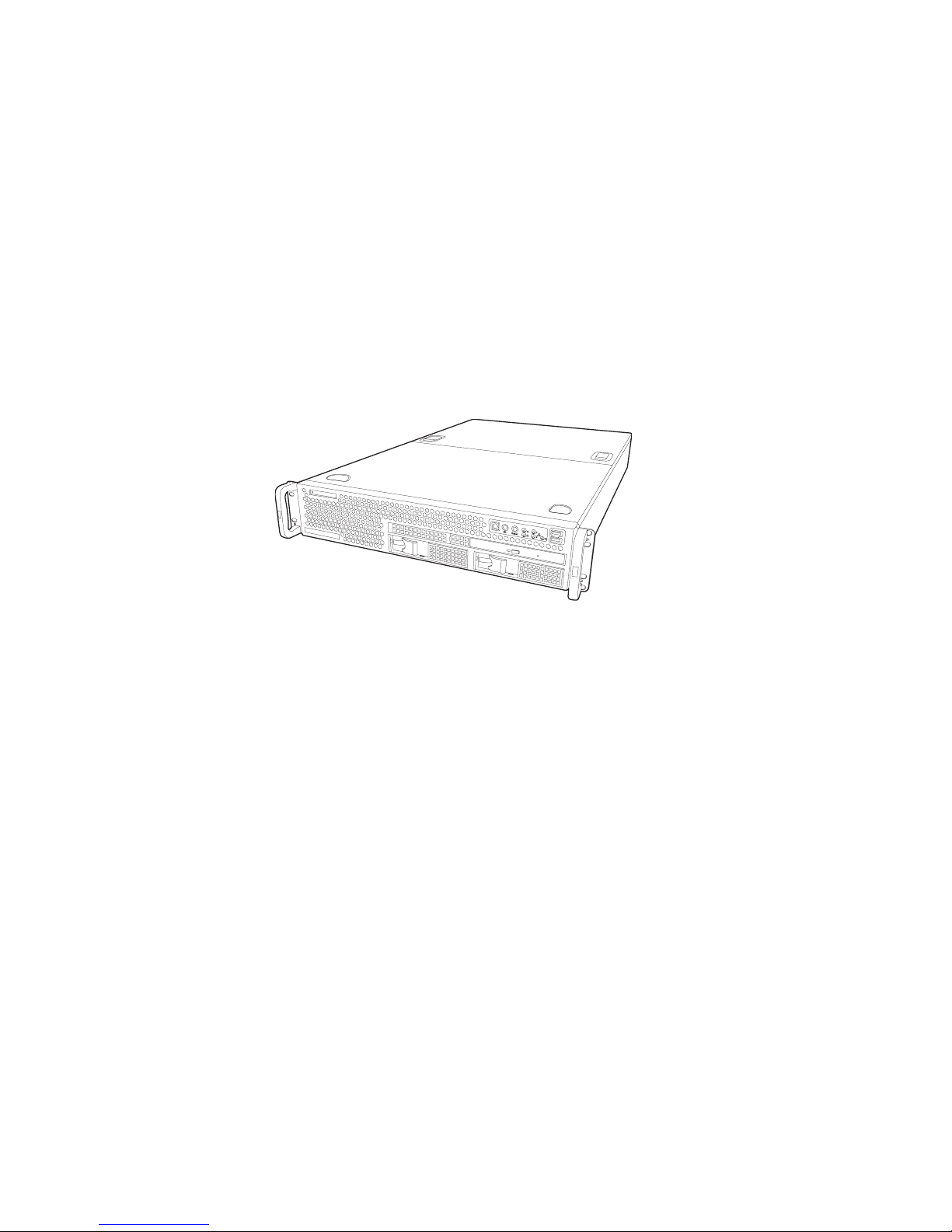
Transport TX46
B4882
User’s Manual
Document part number: D1614-100
Page 2

Preface
Copyright
This publication, including all photographs, illustrations, and software, is protected under international copyright laws, with all rights
reserved. Neither this manual, nor any material contained herein,
may be reproduced without written consent of the manufacturer.
Copyright 2004
Version 1.00
Disclaimer
Information contained in this document is furnished by TYAN
Computer Corporation and has been reviewed for accuracy and reliability prior to printing. TYAN assumes no liability whatsoever, and
disclaims any express or implied warranty, relating to sale and/or
use of TYAN products including liability or warranties relating to fitness for a particular purpose or merchantability. TYAN retains the
right to make changes to product descriptions and/or specifications
at any time, without notice. In no event will TYAN be held liable for
any direct or indirect, incidental or consequential damage, loss of
use, loss of data or other malady resulting from errors or inaccuracies of information contained in this document.
Trademark recognition
All registered and unregistered trademarks and company names
contained in this manual are property of their respective owners
including, but not limited to the following.
TYAN, TYAN S4882T46U2H, Transport TX46, and Thunder K8QS
Pro are trademarks of TYAN Computer Corporation.
AMD, Opteron, and combinations thereof are trademarks of
Advanced Micro Devices Corporation.
Phoenix BIOS, is a trademark of Phoenix Technology.
Broadcom is a trademark of Broadcom Corporation and/or its subsuduries.
Win bond is a trademark of Win bond Electronics Corporation.
ATI, Rage XL, and combinations thereof are trademarks of ATI Corporation.
Silicon Image is a trademark of Silicon Image Inc.
LSI Logic, Fusion MPT™, and LSI are trademarks of LSI Logic Corporation.
Page 3
ii
Federal Communications Commission
Notice for the USA Compliance Information State-
ment (Declaration of Conformity Procedure) DoC
FCC Part 15: This device complies with part 15 of the
FCC Rules
Operation is subject to the following conditions:
1) This device may not cause harmful interference, and
2) This device must accept any interference received including interference that may cause undesired operation. If this equipment does
cause harmful interference to radio or television reception, which
can be determined by turning the equipment off and on, the user is
encouraged to try one or more of the following measures:
• Reorient or relocate the receiving antenna.
• Increase the separation between the equipment and the
receiver.
• Plug the equipment into an outlet on a circuit different from
that of the receiver.
Consult the dealer on an experienced radio/television technician for
help.
Notice for Canada
This apparatus complies with the Class B limits for radio interference as specified in the Canadian Department of Communications
Radio Interference Regulations. (Cet appareil est conforme aux
norms de Classe B d’interference radio tel que specifie par le Ministere Canadien des Communications dans les reglements d’ineteference radio.)
Notice for Europe (CE Mark) This product is in conformity
with the Council Directive 89/336/EEC, 92/31/EEC
(EMC).
CAUTION: Lithium battery included with this board. Do not puncture,
mutilate, or dispose of battery in fire. Danger of explosion if battery
is incorrectly replaced. Replace only with the same or equivalent
type recommended by manufacturer. Dispose of used battery
according to manufacturer instructions and in accordance with your
local regulations.
Page 4

iii
About this manual
This manual provides you with instructions on installing your Transport TX46 (B4882) and consists of the following sections
Overview:
Provides an introduction to the Transport TX46 (B4882) bare bones,
shows a packing list, describes the external components, shows a
table of key components, and provides a block diagram of the system.
Setting up:
Covers procedures for installing the CPUs, memory modules,
optional PCI card, and hard drives.
Replacing pre-installed components:
Covers removal and replacement procedures for pre-installed components.
Appendix:
Provides detailed specifications, maintenance and troubleshooting
procedures, an explanation of BIOS, and technical diagrams.
Page 5

iv
Safety information
Before installing and using the Transport TX46, take note of the following precautions:
• Read all instructions carefully.
• Do not place the unit on an unstable surface, cart, or stand.
• Do not block the slots or openings on the unit which are
provided for ventilation.
• Only use the power source indicated on the marking label.
If you are not sure, contact the power company.
• The unit uses a three-wire grounded cable, which is sup-
plied with a third pin to ground the unit and prevent electric
shock. Do not defeat the purpose of this pin. If your outlet
does not support this type of plug, contact an electrician to
replace the obsolete outlet.
• Do not place anything on the power cord. Place the power
cord where it will not be stepped on.
• Follow all warnings and cautions in this manual and on the
unit case.
• Do not push objects in the ventilation slots as they may
touch high voltage components and result in shock and
damage to the components.
• When replacing parts, ensure that you use parts specified
by the manufacturer.
• When service or repairs have been carried out, perform
routine safety checks to verify that the system is operating
correctly.
• Avoid using the system near water, in direct sunlight, or
near a heating device.
• Cover the unit when not in use.
Page 6

Table of Contents
Chapter 1: Overview
1.1 About the Transport TX46 (B4882)............................................. 1
1.2 Features ........................................................................................ 2
1.3 Unpacking .................................................................................... 4
1.3.1 Box contents .......................................................................... 4
1.3.2 Accessories ............................................................................ 5
1.3.3 Opening the box..................................................................... 6
1.4 About the product......................................................................... 7
1.4.1 System front view and front panel......................................... 7
1.4.2 System rear view.................................................................... 7
1.4.3 System internal view.............................................................. 8
1.4.4 Block diagram........................................................................ 9
Chapter 2: Setting up
2.1 Before you begin .......................................................................... 11
2.1.1 Work area............................................................................... 11
2.1.2 Tools ...................................................................................... 11
2.1.3 Precautions............................................................................. 12
2.2 Installing motherboard components............................................. 13
2.2.1 Removing the chassis cover................................................... 13
2.2.2 Installing CPUs...................................................................... 14
2.2.3 Installing memory.................................................................. 17
2.2.4 Installing a PCI-X/PCI card................................................... 19
2.3 Installing a SCSI hard drive ......................................................... 20
2.4 Rack mounting ............................................................................. 23
Chapter 3: Replacing pre-installed components
3.1 Introduction .................................................................................. 27
3.2 Replacing motherboard components............................................ 27
3.2.1 Disconnecting all motherboard cables ................................... 27
3.2.2 Replacing the motherboard.................................................... 31
3.3 Replacing the slim CD-ROM drive.............................................. 32
3.4 Replacing the floppy disk drive ................................................... 34
3.5 Replacing the LED control board ................................................ 36
3.6 Replacing the storage backplane.................................................. 37
3.7 Replacing the power supply ......................................................... 39
3.8 Replacing the cooling fans ........................................................... 40
3.8.1 Pin header diagram ................................................................ 41
Page 7

Appendix
BIOS.................................................................................................. 43
Introduction.................................................................................... 43
BIOS setup utility .......................................................................... 43
BIOS menu bar .............................................................................. 45
BIOS legend bar............................................................................. 46
BIOS Main Menu........................................................................... 47
System Time .................................................................................. 47
System Date ................................................................................... 48
Legacy Diskette ............................................................................. 48
Primary/Secondary Master/Slave Sub-Menu................................. 48
Extended Memory Testing............................................................. 49
Boot Summary Screen ................................................................... 49
System Memory............................................................................. 49
Extended Memory.......................................................................... 49
BIOS advanced menu .................................................................... 50
Hardware Monitor Sub-Menu........................................................ 50
SMBIOS(DMI) Event Logging Sub-Menu ................................... 51
Reset Configuration Data............................................................... 52
Multiprocessor Specification ......................................................... 52
Use PCI Interrupt Entries in MP Table.......................................... 53
ACPI SRAT Table ......................................................................... 53
HPET Timer................................................................................... 53
Halt on Error .................................................................................. 53
GART Error Reporting .................................................................. 54
4GB Memory Hole Adjust............................................................. 54
Chipset Configuration Sub-Menu.................................................. 54
Keyboard Configuration Sub-Menu .............................................. 56
I/O Device Configuration Sub-Menu ............................................ 56
PCI Configuration Sub-Menu........................................................ 58
Watchdog Timer Option Sub-Menu .............................................. 58
BIOS Security Menu...................................................................... 59
BIOS Power Menu......................................................................... 59
Resume On Time ........................................................................... 59
Intruder Support............................................................................. 60
After Power Failure ....................................................................... 60
BIOS Boot Menu ........................................................................... 60
BIOS Exit Menu ............................................................................ 61
Exit Saving Changes...................................................................... 61
Exit Discarding Changes ............................................................... 61
Load Setup Defaults....................................................................... 61
Discard Changes ............................................................................ 61
Save Changes................................................................................. 62
Page 8

Technical support .............................................................................. 63
Help resources: .............................................................................. 63
Returning merchandise for service ................................................ 63
Page 9
Chapter 1: Overview 1
Chapter 1: Overview
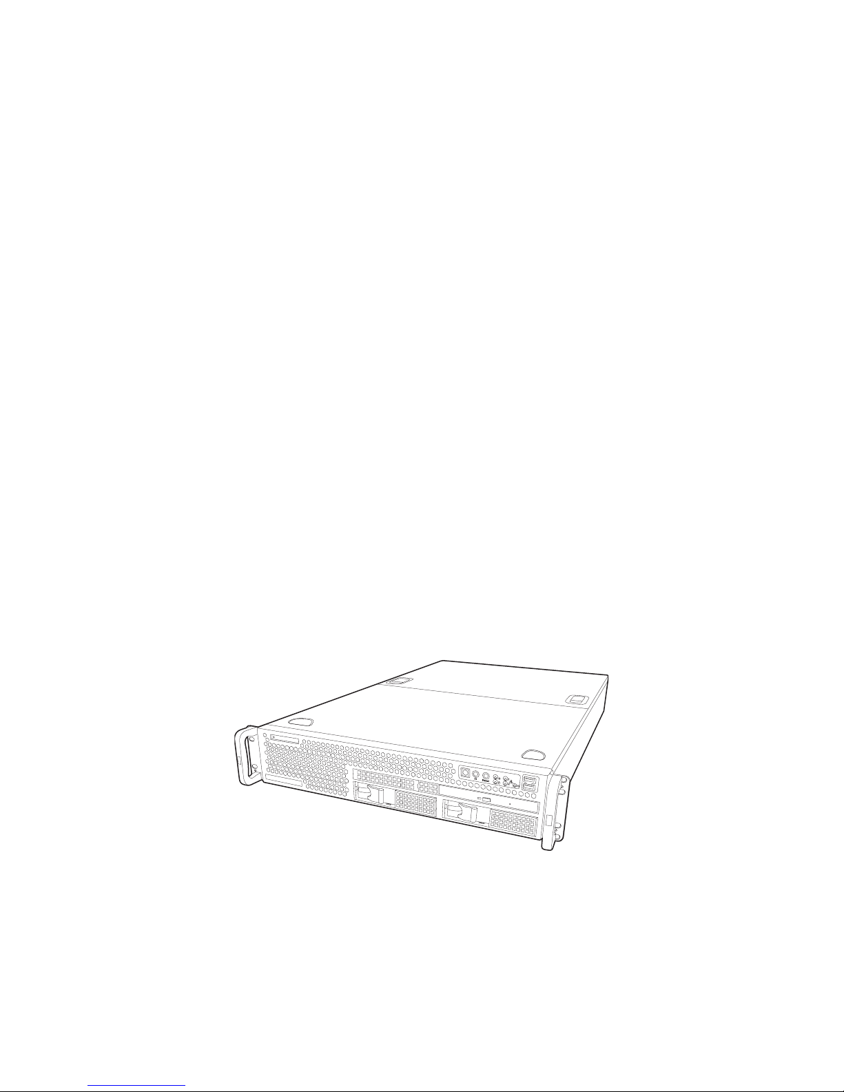
1.1 About the Transport TX46 (B4882T46)
Congratulations on your purchase of the Transport TX46
(B4882T46), the latest in 4-way AMD64 technology available
in a rackmount form factor. Using AMD's revolutionary 64-bit
AMD Opteron™ processor technology, along with a highbandwidth, low-latency memory implementation and a direct
point-to-point HyperTransport™ architecture, the Transport
TX46 offers exceptional computing power and simultaneous
support for 32-bit and 64-bit applications.
Externally-accessible hot-swap SCSI hard drive bays provide
high storage flexibility, while dual Gigabit Ethernet ports
deliver excellent network connectivity, and a slim CD-ROM
drive comes as standard. These features, plus support for
quad AMD Opteron™ 800 Series Processors, up to 32GB of
DDR400 (PC3200) Registered Memory with ECC, onboard
ATI
®
RAGE XL™ video, and PCI-X 133MHz I/O performance, make the TX46 a totally flexible solution for a wide
range of advanced processing applications.
Page 10

1.2 Features
2 Chapter 1: Overview
1.2 Features
Enclosure
• Industry standard, 19-inch rack
mountable, 2U chassis
• (2) External access 3.5-inch HDD
bays
• (1) slim CD-ROM bay
• (1) slim FDD bay
• 701 x 435 x 88 mm (27.5 x 17 x 3.5inch)
Storage
• Supports two hot-swappable SCSI
Ultra 320/160 SCSI hard-disk drives
• Slim 24x CD-ROM drive
• Slim FDD (optional)
• Integrated Storage controller
-Dual channel Ultra 320 SCSI con-
troller (LSI 53C1030) with ZCR support
-4-port SATA I controller (Silicon
Image SiI 3114 with RAID 0,1,10
support)
-(2) IDE channels supported by
South bridge
Processors
• (4) mPGA 940-pin ZIF socket
• Supports up to four AMD
®
Opteron™ 800 series processors
• (4) onboard 3-phase VRMs
• 128 bit DDR dual channel memory
controller integrated into CPU
Networking
• Two Gbit Ethernet ports (Broadcom
®
BCM5704C dual-channel GbE LAN
controller connected to PCI-X bridge
A)
Memory
• 128-bit dual channel memory bus
• (16) 184-pin 2.5V DDR DIMM sockets (Each CPU controls 4 sockets)
• Up to 32 GB of registered DDR
• ECC type memory module support
• Supports PC1600, PC2100,
PC2700, and PC3200 DDR memory
modules
Motherboard
• Tyan Thunder K8QS S4882 Pro
motherboard (13 x 16-inch)
Chipset
• AMD-8131™ HyperTransport PCI-X
Tunnel
• AMD-8111™ HyperTransport I/O
Hub
• Winbond W83627HF Super I/O chip
• (4) Analog Devices LM63 and (1)
ADM1027
BIOS
• Phoenix BIOS on 4MB LPC flash
ROM
• Watchdog timer
• USB boot support
• 48-bit LBA support
• Supports PXE via Ethernet
Page 11

1.2 Features
Chapter 1: Overview 3
Expansion slots
• (2) independent PCI-X buses for
AMD-8131 and (1) legacy PCI bus
for AMD-8111
• (2) 64-bit 133/100 / 66/33 MHz 3.3v
PCI-X slots (Bridge B)
• (2) 64-bit 66/ 33 MHz 3.3 V PCI-X
slots
• (1) 32-bit 33Mhz 5 V PCI slot
• Supports a total of (5) PCI/PCI-X low
profile cards
Server Management
• Optional TYAN SMDC (Server Management Daughter Card), IPMI 1.5
compliant. Supports console redirect
feature.
Power supply
• EPS 12V, 700W with PFC
• 90~264 VAC Full Range Active
PFC; 47~63Hz
Back I/O ports
• Stacked PS/2 mouse and keyboard
ports
• (2) USB 2.0 ports
• (1) 9-pin UART serial port
• (2) RJ-45 LAN ports
• (1) 15-pin VGA port
Front panel Features
• (2) USB 1.1 ports
• HDD activity, LAN
activity, and power LEDs
• Power and reset switches
• System ID switch and LED
Video
•ATI
®
Rage™ XL PCI Graphics con-
troller with 8MB video memory
Regulatory
• FCC Class B
(declaration of conformity)
• CE (declaration of conformity)
Page 12

1.3 Unpacking
4 Chapter 1: Overview
1.3 Unpacking
1.3.1 Box contents
This section describes the TX46 package contents and
accessories.
Component Description
Industry standard 2U chassis, (2) swappable
HDD bays
Tyan Thunder K8QS S4882 Pro motherboard (pre-installed)
24x slim CD-ROM drive (pre-installed)
SCSI backplane and holding bracket (preinstalled)
LED and USB control board (pre-installed)
EPS 12V 700W PSU (pre-installed)
(4) Fans (80 mm x 80 mm)
Page 13

1.3 Unpacking
Chapter 1: Overview 5
1.3.2 Accessories
(2) mounting ears
(1) 34-pin FDD cable
(4) CPU heat sinks with fans
(2) Sliding rails
Tyan K8QS (S4882) Pro motherboard
user manual and Transport TX46
(B4882T46) hardware installation guide
Driver CD and diskettes
S2882
K8S Pro AJS
#D 1528 - 100
Revision 1.0
High Performance Motherboard
User's Manual
2U Server Platform
B2882
Transport TA26
ID : 1540 - 100
Revision 1.0
Hardware
Installation Guide
Adaptec
Window
48-10
Silicon
R
Driver
Windows
XP
V
V
Disk
Image
SiI3114
2000/
bit
( 32 )
/2003
1.2.0.5
OSE P N:
/
48-1000-132
Silicon
IDE
Driver
Windows
XP
V
V
Disk
Image
SiI3114
2000/
bit
( 32 )
/2003
1.2.0.5
OSE P N:
/
48-1000-132
WWW.tyan.com
01010
Basic
Driver
Version
WWW.tyan.com
M2.0
CD
01010
Page 14
1.3 Unpacking
6 Chapter 1: Overview
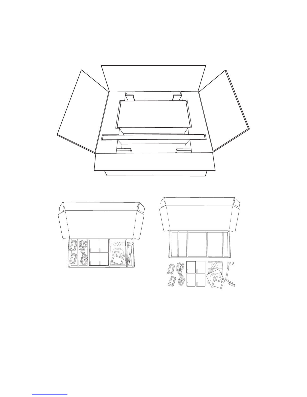
1.3.3 Opening the box
Open the box carefully and ensure that all components are
present and undamaged. The product should arrive packaged as illustrated below.
Contact your distributor if anything is missing or appears
damaged.
1
U
2
-W
a
y
S
e
r
v
e
r
P
la
tfo
r
m
B
4
8
8
2
T
r
a
n
s
p
o
r
t
T
X
4
6
I
D
:
1
5
4
0
-
1
0
0
R
e
v
i
s
i
o
n
1
.
0
Hard
w
are
In
stalla
tion
G
uide
h
t
t
p
:
//
ww
w
.
t
y
a
n
.
c
o
m
1U
2
-Wa
y Ser
ver Pla
tfo
r
m
B
4
8
8
2
T
ransport
TX46
I
D
:
1
5
4
0
1
0
0
Revision 1.0
H
a
r
d
w
a
r
e
In
s
t
a
lla
t
io
n
G
u
id
e
ht
t
p
:
//
ww
w
.ty
a
n
.c
o
m
Packaged box contents
Accessory pack
Packaged accessories
Page 15

1.4 About the product
Chapter 1: Overview 7
1.4 About the product
This section contains hardware diagrams and a block diagram of the TX46 (B4882) system.
1.4.1 System front view and front panel
See the diagram below for details of the front panel indicators
and switches.
1.4.2 System rear view
ID ID
1
2
Reset
disc
ID ID
1
2
Reset
Power indicator
Reset button
Power button
ID button
IDE activity
indicator
LAN activity
indicator
ID indicator
USB
ports
HDD access/busy
indicator
(Flashes green during
read/write process)
AC in socket
Stacked PS/2 mouse and
keyboard ports
USB ports
Serial port
Gbit LAN ports
VGA port
ID LED
Page 16

1.4 About the product
8 Chapter 1: Overview
1.4.3 System internal view
1 Slim CD-ROM drive 2 Slim FDD drive bay (option)
3 EPS 12V 700W power supply 4 System fans
5 IDE connector 6 FDD connector
7 SCSI connectors 8 PCI-X/PCI slots
9 Parallel port connector 10 CPU sockets
11 Memory slots 12 SCSI cable
13 SCSI backplane 14 Front panel cable
2
3
4
5
6
7
8
9
10
11
14
13
12
1
Page 17

1.4 About the product
Chapter 1: Overview 9
1.4.4 Block diagram
DIMM0
DIMM1
DIMM2
DIMM3
DIMM3
DIMM2
DIMM1
DIMM0
DIMM3
DIMM2
DIMM1
DIMM0
DIMM0
DIMM1
DIMM2
DIMM3
CPU1
CPU0
PCI-X
8131
8111
CPU3
CPU2
I/O Hub
PCI-X SLOT
PCI-X SLOT
PCI SLOT
PCI-X SLOT
PCI-X SLOT
SATA port
SATA port
SATA port
SATA port
USB2.0 x 2port
SATA SIL3114
ATI RAGE XL
VT6212 USB2.0
LPC ROM
ADM1027
SMDC
LPC Super I/O
w83627HF
LSI1030
U320 SCSI
Broadcom
5704C
ATA ports X 2
USB1.1x2 header
USB1.1x2 header
Floppy
PS/2
Parallel
Serial x 2
200-33MT/s
144-Bit
200-33MT/s
144-Bit
200-33MT/s
144-Bit
200-33MT/s
144-Bit
16x16 HT
1600MT/s
16x16 HT
1600MT/s
16x16 HT
1600MT/s
16x16 HT
1600MT/s
16x16 HT
1600MT/s
64-bit 133MHz
PCI-X Bus
64-bit 133MHz
PCI-X Bus
32-bit
33MHz
LPC
8X8 HT
400 MT/s
Page 18

Memo
Page 19

Chapter 2: Setting up 11
Chapter 2: Setting up
2.1 Before you begin
This chapter explains how to install motherboard components
including CPUs, memory modules, and PCI cards. There are
also instructions in this section for installing SATA, SCSI, and
IDE hard drives.
Careful attention should be given to the precautions mentioned in this section when setting up your system.
2.1.1 Work area
Make sure you have a stable, clean working environment.
Dust and dirt can get into components and cause malfunctions. Use containers to keep small components separated.
Putting all small components in separate containers prevents
them from becoming lost. Adequate lighting and proper tools
can prevent you from accidentally damaging the internal
components.
2.1.2 Tools
The following tools will be required to complete the installations described in this chapter.
• A cross head (Phillips) screwdriver
• A grounding strap and/or anti static pad
Most of the electrical and mechanical connectors in your system can be disconnected using your fingers. It is recommended that you do not use needle-nosed pliers to remove
connectors as these can damage the soft metal or plastic
parts of the connectors.
Page 20

2.1 Before you begin
12 Chapter 2: Setting up
2.1.3 Precautions
Components and electronic circuit boards can be damaged
by static electricity. Working on a system that is connected to
a power supply can be extremely dangerous. Follow the
guidelines below to avoid damage to the Transport TX46 or
injury to yourself.
• Disassembly of this system should only be attempted
by experienced engineers.
• Ground yourself properly before removing the top
cover of the system. Unplug the power from the
power supply and then touch a safely grounded
object to release static charge (i.e. power supply
case). If available, wear a grounded wrist strap. Alternatively, discharge any static electricity by touching
the bare metal chassis of the unit case, or the bare
metal body of any other grounded appliance.
• Avoid touching motherboard components, IC chips,
connectors, memory modules, and leads.
• The motherboard is pre-installed in the system.
When removing the motherboard, always place it on
a grounded anti-static surface until you are ready to
reinstall it.
• Hold electronic circuit boards by the edges only. Do
not touch the components on the board unless it is
necessary to do so. Do not flex or stress circuit
boards.
• Leave all components inside the static-proof packag-
ing that they ship with until they are ready for installation.
• After replacing optional devices, make sure all
screws, springs, or other small parts are in place and
are not left loose inside the case. Metallic parts or
metal flakes can cause electrical shorts.
• Always use the correct size screws and fixings when
installing or replacing components.
Note: All connectors are designed to fit
one way only, no force should be required to
make a connection.
Page 21
2.2 Installing motherboard components
Chapter 2: Setting up 13
2.2 Installing motherboard components
This section describes how to install CPUs, memory modules, and PCI cards in the Transport TX46.
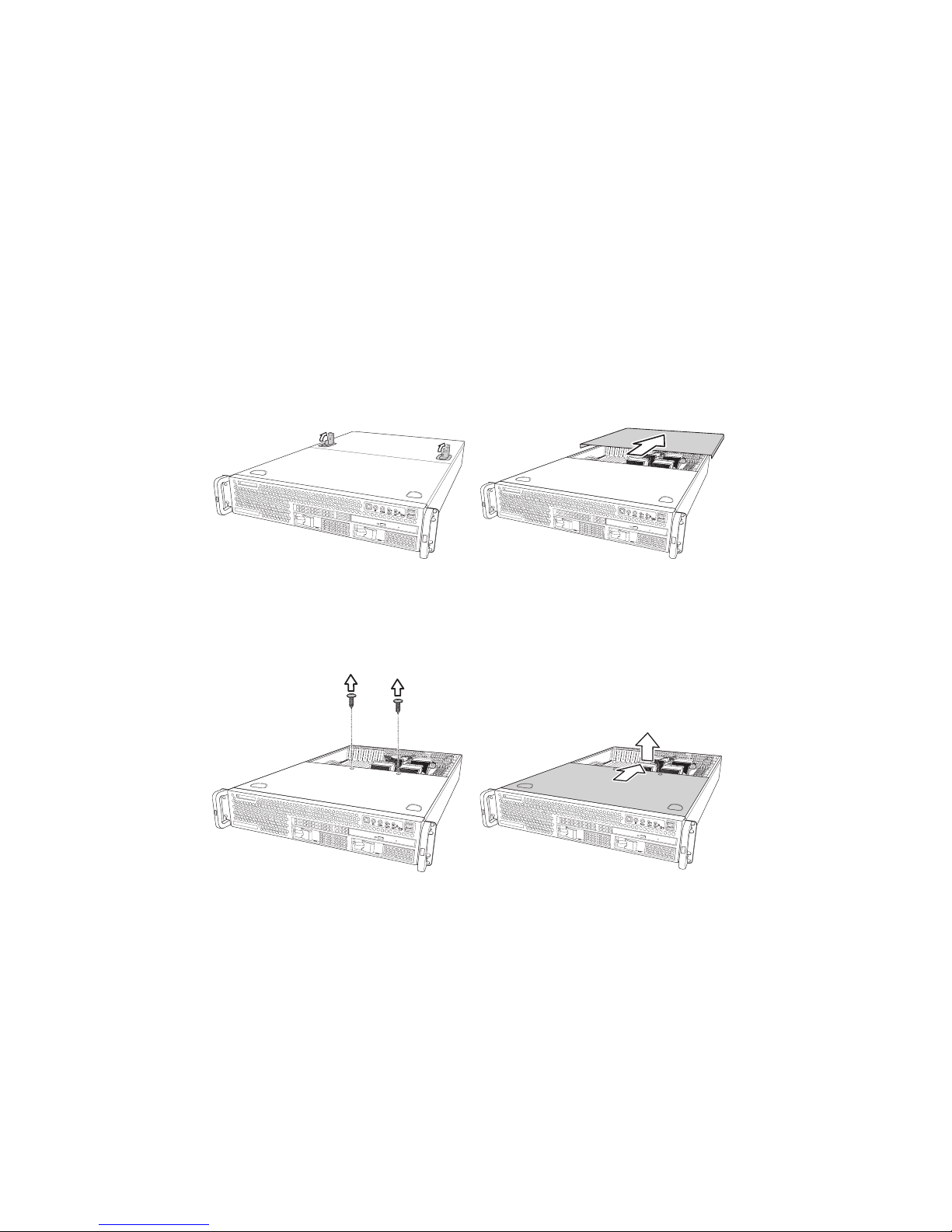
2.2.1 Removing the chassis cover
Follow these instructions to remove the TX46 chassis cover.
This step is required before any other procedures in this
chapter can be undertaken.
To remove the rear cover and expose motherboard
components:
1. Pull up the two retaining clips, and lift off the cover.
To remove the front cover and expose storage media, cooling
fans and power supply:
1. Remove the two screws and lift off the cover.
Note: The front cover cannot be removed
without first removing the rear cover.
Page 22
2.2 Installing motherboard components
14 Chapter 2: Setting up
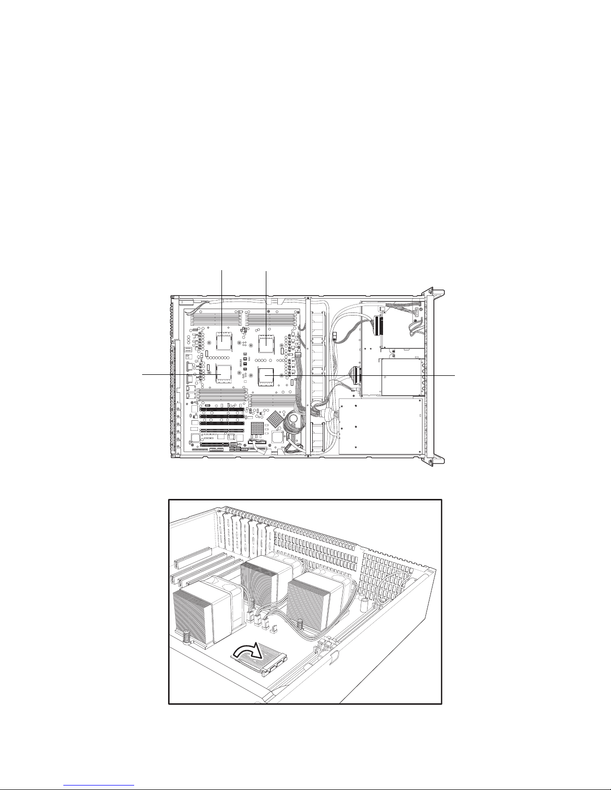
2.2.2 Installing CPUs
This section describes how to install AMD Opteron processors and heat sinks in your TX46 system.
Note: The system supports up to four
CPUs. CPU0 must be installed first followed
by 1, 2, and 3.
1. Remove the rear chassis cover as described in section
2.2.1 Removing the chassis cover.
2. Locate the processor sockets on the motherboard.
3. Lift the locking lever as shown.
CPU0
CPU1CPU3
CPU2
Page 23

2.2 Installing motherboard components
Chapter 2: Setting up 15
4. Place the processor in the socket, making sure that pin 1
is correctly located.
Note: The processor will only fit in the
socket one way. No force should be required
to insert the processor.
5. Push the locking lever back down into the locked position
as shown.
6. Apply some thermal grease to the top of the processor
Note: It is essential that thermal grease
(heat sink compound) is applied to the processors before the heat sink is installed to
ensure that the heat sink works efficiently.
Page 24

2.2 Installing motherboard components
16 Chapter 2: Setting up
7. Place the heat sink on top of the processor with the fan to
the rear of the chassis as shown.
Note: All heat sinks must be installed with
fans facing the rear of the chassis to ensure
efficient cooling.
8. Tighten the two screws on the heat sink to secure them in
place.
Note: Each heat sink should be secured
with two screws, each with a spring beneath
them. When installing or removing heat sinks
the two screws should be turned alternately,
a little at a time, to prevent the heat sink form
springing up on one side, or being tightened
down unevenly.
9. Connect the fan to the appropriate pin header as shown.
Page 25

2.2 Installing motherboard components
Chapter 2: Setting up 17
2.2.3 Installing memory
Follow the instructions in this section to install memory modules in your TX46 system.
1. Remove the rear chassis cover as described in section
2.2.1 Removing the chassis cover.
2. Locate the memory slots on the motherboard.
3. Press the memory slot locking levers in the direction of
the arrows as shown below.
4. The module will fit only one way in the slot. Ensure that
indentations in the memory module line up with corresponding notch in the memory slot.
Memory slots
Page 26

2.2 Installing motherboard components
18 Chapter 2: Setting up
5. Insert the memory module into the slot as shown.
The locking levers will fall into position.
Note: You may have to push one end of
the memory slot firmly into place before easing the other end into position.
6. Ensure that the locking levers are firmly in place and that
the memory module is properly seated in the slot.
Note: Each bank memory of sockets is
associated with one CPU. Memory will be
recognized only when installed in a socket
associated with an installed CPU.
Note: When installing memory, install the
first module in CPU0_DIMM_0 or
CPU0_DIMM2. For best performance, balance memory modules equally between
CPUS.
Page 27

2.2 Installing motherboard components
Chapter 2: Setting up 19
2.2.4 Installing a PCI-X/PCI card
Follow the instructions in this section to install a PCI-X/PCI
card in your TX46 system.
1. Remove the rear chassis cover as described in section
2.2.1 Removing the chassis cover.
2. Remove the blanking plate from the slot you wish to use.
3. Insert a PCI-X/PCI card into the slot, making sure it is
firmly seated.
Page 28

2.3 Installing a SCSI hard drive
20 Chapter 2: Setting up
4. Replace the screw as shown.
Note: PCI-X slots B0 and B1 can support
up to 133 MHz (also 100 and 66 MHz). Set
jumpers J39 and J24 accordingly. (See
motherboard manual). PCI-X slots A0 and
A1 can support 66 MHz only.
2.3 Installing a SCSI hard drive
Follow these instructions to install a hot-swappable SCSI
hard drive in your TX46 system.
1. Pull out the locking lever and pull the tray out of the chassis.
PCI-X B0
PCI-X A0
PCI-X A1
PCI-X B1
Page 29

2.3 Installing a SCSI hard drive
Chapter 2: Setting up 21
2. Remove the four screws holding the plastic spacer in the
tray and remove the spacer from the tray.
.
3. Place a SCSI hard drive in the drive trayand secure with
four screws.
Note: The TX46 supports SCSI drives with
80 pin interfaces only.
80-pin SCA II interface
Page 30

2.3 Installing a SCSI hard drive
22 Chapter 2: Setting up
4. Slide the drive tray back into the chassis and press the
locking lever into place.
Note: The TX46 is shipped with SCSI
backplane and cables pre-installed.
Note: Care should be taken not to damage
the delicate light pipe when handling the
HDD trays.
Light pipe
Page 31

2.4 Rack mounting
Chapter 2: Setting up 23
2.4 Rack mounting
Follow these instructions to mount the TX46 into an industry
standard 19-inch rack.
Note: Before mounting the Transport TX46
in a rack, ensure that all internal components
have been installed and that the unit has
been fully tested. Maintenance can be performed on the unit while in a rack but it is
preferable to install the device in a fully operational condition.
1. Attach the mounting ears to the TX46 as shown using
four screws from the supplied nuts, screws, and washers
kit.
2. Attach the sliding rail mounting brackets to the sliding
rails as shown, using the short black screws from the
supplied nuts, screws, and washers kit.
3. Fully extend the sliding rails until they lock.
Page 32

2.4 Rack mounting
24 Chapter 2: Setting up
4. Attach each sliding rail to the side of the TX46 as shown,
using three short, silver colored screws from the supplied
nuts, screws, and washers kit, for each rail.
5. Return the sliding rails to their shortest position.
6. With the rails in their shortest position, adjust both front
mounting brackets so that they are flush with the front of
the unit.
Page 33

2.4 Rack mounting
Chapter 2: Setting up 25
7. Accurately measure the depth of your rack and adjust the
rear brackets accordingly.
8. When all brackets are positioned correctly, tighten them.
9. Lift the unit into place in the rack and screw it into place
as shown.
Note: To avoid injury, it is strongly recom-
mended that two people lift the TX46 into
place while a third person install it in the
rack.
Page 34

Memo
Page 35

Chapter 3: Replacing pre-installed components 27
Chapter 3: Replacing pre-installed
components
3.1 Introduction
This chapter describes how to replace all the pre-installed
components of your TX46, including PCI card, motherboard,
CD-ROM drive, optional floppy disk drive, and LED control
board. There is also a section covering the replacement of
the 2-port SCSI backplane.
Before you attempt to replace any components, make sure
you have read section 2.1 Before you begin, which describes
the precautions you need to take and the tools you will
require.
3.2 Replacing motherboard components
Follow these instructions to remove motherboard
components and replace the motherboard.
3.2.1 Disconnecting all motherboard cables
When replacing the motherboard or certain motherboard
components, it may be necessary to remove cables connected to the motherboard. Follow these instructions to
remove all motherboard cabling. See Technical support in the
Appendix for detailed diagrams of cable locations.
Page 36

3.2 Replacing motherboard components
28 Chapter 3: Replacing pre-installed components
1. Disconnect the power cables.
2. Disconnect the CD-ROM drive IDE cable.
Note: If there is an FDD or IDE HDD
installed in the bay beneath the CD-ROM
drive, disconnect the FDD/HDD cables
before removing the motherboard.
Page 37

3.2 Replacing motherboard components
Chapter 3: Replacing pre-installed components 29
3. Disconnect the front panel LED and USB connectors.
4. Disconnect the SCSI cable from the motherboard.
Page 38

3.2 Replacing motherboard components
30 Chapter 3: Replacing pre-installed components
5. Disconnect optional floppy drive cable (if installed).
Page 39

3.2 Replacing motherboard components
Chapter 3: Replacing pre-installed components 31
3.2.2 Replacing the motherboard
Follow these instructions to remove the motherboard from
your TX46.
Note: Before proceeding, you must
remove all cable connections to the motherboard. See section 3.2.1 Disconnecting all
motherboard cables.
1. Remove the rear chassis cover. See 2.2.1 Removing the
chassis cover
2. Remove the heat sinks and processors if installed. See
2.2.2 Installing CPUs.
3. Remove the ten screws that secure the motherboard to
the chassis.
Page 40

3.3 Replacing the slim CD-ROM drive
32 Chapter 3: Replacing pre-installed components
4. Carefully lift the motherboard from the chassis.
Note: The motherboard is too large to lift
straight out. Lift the front edge of the motherboard up to an angle of about 45°. Then slide
the motherboard out, front end first.
3.3 Replacing the slim CD-ROM drive
This section describes how to remove and replace the CDROM drive in your TX46 system.
1. Remove the front and rear chassis covers as described
in section 2.2.1 Removing the chassis cover.
2. Locate the drive bay housing the slim CD-ROM drive and
remove the power and data cables from the backplane.
Page 41

3.3 Replacing the slim CD-ROM drive
Chapter 3: Replacing pre-installed components 33
3. Remove the two screws that secure the CD-ROM backplane to the CD-ROM drive.
4. Remove the single screw that secures the drive bay to
the chassis and lift the drive bay free.
5. Remove the 4 screws that secure the CD ROM drive in
the drive bay and remove it.
6. Install a new CD-ROM in the drive bay and secure with
four screws.
Page 42

3.4 Replacing the floppy disk drive
34 Chapter 3: Replacing pre-installed components
7. Replace the CD-ROM backplane and secure with two
screws.
8. Replace the drive bay in the chassis and secure with a
single screw.
9. Replace the power and data cables.
3.4 Replacing the floppy disk drive
Follow these instructions to replace the FDD in your TX46.
1. Remove the front and rear chassis covers as described
in section 2.2.1 Removing the chassis cover.
2. Locate the FDD drive bay and remove the power and
data cables from the backplane.
3. Remove the single screw that secures the drive bay to
the chassis.
Page 43

3.4 Replacing the floppy disk drive
Chapter 3: Replacing pre-installed components 35
4. Slide the drive housing back and lift it free from the chassis.
5. If no FDD is installed, you will need to remove the blanking plate from the front panel and the grill from the front of
the drive bay as shown.
6. Install a new FDD in the bay and secure with four screws.
7. Replace the drive tray in the chassis and secure with a
single screw.
8. Replace the power and data cables.
Front panel blanking plate
Page 44

3.5 Replacing the LED control board
36 Chapter 3: Replacing pre-installed components
3.5 Replacing the LED control board
Follow these instructions to replace the LED control board.
1. Remove the front and rear chassis covers as described
in section 2.2.1 Removing the chassis cover.
2. Remove all the cables from the LED control board.
3. Remove the three screws that secure the board to the
chassis and lift it free.
Page 45

3.6 Replacing the storage backplane
Chapter 3: Replacing pre-installed components 37
3.6 Replacing the storage backplane
This section describes how to replace the SATA backplane
on your TX46.
1. Remove the front and rear chassis covers as described
in section 2.2.1 Removing the chassis cover.
2. Remove the power and data cables from the SCSI backplane as shown.
3. Remove the three screws that secure the backplane in
place.
Page 46

3.6 Replacing the storage backplane
38 Chapter 3: Replacing pre-installed components
4. Remove the backplane from the chassis.
5. Secure a new backplane in place with three screws.
6. Reconnect the power and data cables.
Page 47

3.7 Replacing the power supply
Chapter 3: Replacing pre-installed components 39
3.7 Replacing the power supply
Follow these instructions to replace the power supply in your
TX46 system.
1. Remove the front and rear chassis covers as described
in section 2.2.1 Removing the chassis cover.
2. Remove the single screw that secures the grounding wire
to the chassis as shown.
3. Pull the two spade connectors off the terminals on the
back of the AC power socket.
4. Remove the two screws that secure the power supply to
the chassis and lift the unit free.
5. Secure the new unit in place with two screws, reconnect
the spade connectors on the AC power socket and
reconnect the grounding wire to the chassis.
Note: For safety reasons, it is essential
that the grounding wire is connected to the
chassis.
Page 48

3.8 Replacing the cooling fans
40 Chapter 3: Replacing pre-installed components
3.8 Replacing the cooling fans
Follow these instructions to replace the cooling fans in your
TX46 system.
1. Remove the front and rear chassis covers as described
in section 2.2.1 Removing the chassis cover.
2. Locate the power supply for the fan you wish to replace
on the motherboard and unplug it.
3. Remove the two screws that secure the fan to the chassis.
4. Pull the fan away from the mounting point and lift it free.
Page 49

3.8 Replacing the cooling fans
Chapter 3: Replacing pre-installed components 41
3.8.1 Pin header diagram
The diagram below shows the motherboard pin headers that
supply power to the cooling fans.
CPU cooling fan pin headers
Chassis cooling fan pin headers
Page 50

Memo
Page 51

43
Appendix
BIOS
Introduction
Your Transport TX46 (B4882) system includes a powerful
TYAN Thunder K8QS S4882 motherboard with Phoenix
BIOS on 4 MB LPC flash ROM.
The BIOS is the motherboard’s basic input/output system.
The BIOS contains all the settings required to control the keyboard, display, disk drives, serial communications, and a
number of miscellaneous functions. This section of the
appendix describes the various BIOS settings that can be
used to configure your system.
BIOS setup utility
With the BIOS setup utility, you can modify BIOS settings and
control the special features of your computer. The setup utility uses a number of menus for making changes and turning
the special features on or off.
Note: All menus are based on a typical
system. The actual menus displayed on your
screen may be different and depend on the
hardware and features installed in your computer.
To start the BIOS setup utility:
1. Turn on or reboot your system.
2. Press <F2> during POST to start the BIOS setup utility.
Page 52

44
BIOS setup utility
To select an item
Use the left/right (
ÅÆ) arrow keys to make a selection.
To display a sub-menu (A pointer
X marks all sub menus)
Use the arrow keys to move the cursor to the sub menu you
want. Then press <Enter>.
Main Advanced Security Power Boot Exit
System Time
System Date
Legacy Diskette A:
XPrimary Master
XPrimary Slave
XSecondary Master
XSecondary Slave
HDD Post Write Buffer:
Large Disk Access Mode:
Extended Memory Testing
Boot Summary Screen:
System Memory:
Extended Memory:
[12:59:59]
[11/01/2002]
[1.44/1.25MB 3”]
[None]
[None]
[None]
[None]
[Enabled]
[DOS]
[Just zero it]
[Disabled]
624 KB
5024 MB
Item Specific Help
<Tab>, <Shift-Tab>, or
<Enter> selects field
F1 Help
ÇÈSelect Item -/+ Change Values F9 Setup Defaults
ESC Exit
ÅÆ Select Menu Enter Select XSub-Menu F10 Save and Exit
Page 53

45
BIOS menu bar
The menu bar at the top of the window lists the following
selections:
Menu bar selections
Note: Options written in bold type repre-
sent the BIOS setup default.
Main To configure basic system setups
Advanced To configure the chipset features
Security To configure user and supervisor passwords
Power To configure power management features
Boot To configure system boot order
Exit To exit setup utility
Page 54

46
BIOS legend bar
The following chart describes the legend keys and their functions.
BIOS legend bar
Key Function
<F1> or <Alt-H> General help window
<ESC> Exit current menu
ÅÆ arrow keys Select a different menu
ÇÈ arrow keys Move cursor up/down
<Tab> or <Shift-Tab> Cycle cursor up/down
<Home> or <End> Move cursor to the top or bottom of the window
<PgUp> or <PgDn> Move cursor to the next or previous page
<F5>, or <-> Select the previous value/setting of the field
<F6>, <+>, or <Space> Select the next value/setting of the field
<F9> Load the default configuration values
<F10> Save and exit
<Enter> Execute command or select submenu
<Alt-R> Refresh screen
Page 55

47
BIOS Main Menu
The Main BIOS menu is the first screen that appears when
you enter BIOS setup. The menu has two main frames. The
left frame displays all the options that can be configured.
"Grayed-out" options cannot be configured, and options in
blue can be changed.
The right frame displays the key legend. Above the key legend is an area reserved for a text message. When an option
is selected in the left frame, it is highlighted in white. Often, a
text message will accompany it.
BIOS main menu
System Time
Main Advanced Security Power Boot Exit
System Time
System Date
Legacy Diskette A:
XPrimary Master
XPrimary Slave
XSecondary Master
XSecondary Slave
HDD Post Write Buffer:
Large Disk Access Mode:
Extended Memory Testing
Boot Summary Screen:
System Memory:
Extended Memory:
[12:59:59]
[11/01/2002]
[1.44/1.25MB 3”]
[None]
[None]
[None]
[None]
[Enabled]
[DOS]
[Just zero it]
[Disabled]
624 KB
5024 MB
Item Specific Help
F1 Help
ÇÈSelect Item -/+ Change Values F9 Setup Defaults
ESC Exit
ÅÆ Select Menu Enter Select XSub-Menu F10 Save and Exit
Feature Option Description
HH: MM: SS - Set the system time.
Page 56

48
System Date
Legacy Diskette
Primary/Secondary Master/Slave Sub-Menu
Feature Option Description
MM: DD: YYYY - Set the system date.
Feature Option Description
Legacy Diskette 360 KB
1.3 MB
720 KB
1.44/1.25 MB
2.88 MB
This setting selects the
type of the floppy disk
drive installed in the
system.
Feature Option Description
Type Auto Auto - The BIOS auto-
matically determines
the IDE drive type.
Multi-Sector Transfers -- When enabled, the
hard drive can transfer
data from multiple sectors at a time.
LBA Mode Control -- When enabled, this
allows the BIOS to
support hard drives
larger than 8GB.
32 Bit I/O Enabled
Disabled
This setting enables or
disables 32 bit IDE
data transfers.
Transfer Mode: -- Displays the Transfer
Mode of the plugged in
IDE device.
Ultra DMA Mode -- Displays the Ultra DMA
modes, which the IDE
device supports.
Page 57

49
Extended Memory Testing
Boot Summary Screen
System Memory
Extended Memory
Feature Option Description
Extended Memory Testing
Disable
Just zero it
Enable
Determines the type of
tests that will be performed on extended
memory.
Feature Option Description
Boot Summary Screen Disable
Enable
Displays system
configuration on boot.
Feature Option Description
System Memory -- Displays the size of
system memory.
Feature Option Description
Extended Memory -- Displays the size of
extended memory.
Page 58

50
BIOS advanced menu
You can select any item in the left frame of the screen, such
as Super I/O Configuration, to go to the submenu for that
item. You can display an Advanced BIOS Setup option by
highlighting it using the <Arrow> keys. All Advanced BIOS
Setup options are described in this section. The Advanced
BIOS Setup screen is shown below.
BIOS advanced menu
Hardware Monitor Sub-Menu
Main Advanced Security Power Boot Exit
XHardware Monitor
XSMBIOS(DMI) Event Logging
XConsole Redirection
Installed O/S:
Reset Configuration Data:
Multiprocessor Specification:
Use PCI Interrupt Entries in MP Table:
ACPI SRAT Table:
RSDT FADT Revision:
HPET Timer:
Halt on Error:
GART Error Reporting
4GB Memory Hole Adjust
4GB Memory Hole Size
XChipset Configuration
XKeyboard Configuration
XI/O Device Configuration
XPCI Configuration
XWatchdog Timer Option
[Other]
[No]
[1.4]
[Yes]
[Enable]
[1]
[Enable]
[Yes]
[Disable]
[Auto]
[64 MB]
Item Specific Help
F1 Help
ÇÈSelect Item -/+ Change Values F9 Setup Defaults
ESC Exit
ÅÆ Select Menu Enter Select XSub-Menu F10 Save and Exit
Description
This screen contains information from motherboard hardware monitor sensors,
such as temperature, fan speed and voltage.
Page 59

51
SMBIOS(DMI) Event Logging Sub-Menu
Feature Option Description
View DMI event log -- Displays the contents
of the DMI event log.
Clear all DMI event logs No
Yes
Setting this to ‘Yes’ will
clear the DMI event log
after rebooting
Event Logging Enable
Disable
Select ‘Enable’ to allow
logging of
DMI events.
ECC Event Logging Enable
Disable
Select ‘Enable’ to allow
logging of
ECC events.
Mark DMI events as read -- Press Enter to mark all
DMI events in
the event log as read.
Com Port Address Disabled
On-board COM port A
If the console redirection function is
enabled, it will use the
COM A port on the
motherboard.
Console connection Direct
Via modem
Indicates whether the
console is
connected directly to
the system or a
modem is used to connect.
Baud Rate 300 /1200 /2400
/9600 /19.2k
/38.4k /57.6k
/115.2k
Selects the baud rate
of transfer
Flow Control None
XON/XOFF
CTS/RTS
Selects the Flow Control mode
Console Type vt100
vt100 8bit
ANSI 7bit
ANSI
Vt100 plus
UTF8
Selects the console
type.
Page 60

52
Reset Configuration Data
Multiprocessor Specification
Continue C.R. after
POST
Off
on
Enables Console Redirection after the OS
has loaded.
Installed O/S [other]
Win95
Win98
WinMe
Win2000
Selects the operating
system installed
on your system, which
you will use
most commonly. Note.
An incorrect
setting can cause
some operating
systems to display
unexpected
behavior.
Feature Option Description
Reset Configuration
Data
Yes
No
This setting erases all
configuration data in a
section of memory for
ESCD (Extended
System Configuration
Data) that stores the
configuration settings
for non-PnP plug-in
devices. Select Yes
when required to
restore
the manufacturer's
defaults.
Feature Option Description
Multiprocessor Specification
1.4
1.1
Configures the MP
Spec revision
level. Some OS will
require 1.1 for compatibility reasons.
Feature Option Description
Page 61

53
Use PCI Interrupt Entries in MP Table
ACPI SRAT Table
HPET Timer
Halt on Error
Feature Option Description
Use PCI Interrupt Entries
in MP
Table
Yes
No
Configures the MP
Table with PCI
interrupt entries.
Feature Option Description
ACPI SRAT Table Enable
Disable
Enables ACPI 2.0
static resources
affinity table for
ccNUMA systems.
RSDT FADT Revision 1
2
Configures the MP
Table with PCI
interrupt entries.
Feature Option Description
HPET Timer Enable
Disable
Enables the HPET high
precision event
timer.
Feature Option Description
Halt on Error Yes
No
BIOS will halt POST
and wait for user
input in case of POST
errors.
Page 62

54
GART Error Reporting
4GB Memory Hole Adjust
Chipset Configuration Sub-Menu
Feature Option Description
GART Error Reporting Enable
Disable
This option should
remain disabled for
normal operation. The
driver
developer may enable
it for the purposes of
testing.
Feature Option Description
4GB Memory Hole
Adjust
Auto
Manual
Auto – Adjusts the
memory hole size
automatically according to the memory
space used by PCI
devices.
Manual – Memory hole
size is determined
manually.
Feature Option Description
DRAM Bank Interleave Auto
Disable
Interleave memory
blocks across DRAM
chip selects. BIOS will
AUTO detect
capability on each
Node.
Page 63

55
Node memory Interleave Disable
AUTO
Interleave memory
blocks across
processor nodes BIOS
will AUTO detect capability of Memory System.
Note: This cannot be
enabled if ACPI
SRAT table is also
enabled. Changing one
value will also toggle
the other.
ECC Enable
Disable
ECC check/correct
mode. This enables
function for all blocks
within the
core and North Bridge.
DRAM ECC Enable
Disable
If all memory in the
system supports ECC,
enabling this will scrub
DRAM and enable the
system requests to
DRAM to be checked
and/or corrected.
ECC Scrub Redirection Enable
Disable
Enables ECC Scrubber
to correct errors
detected in DRAM during normal CPU
requests.
4-bit ECC Enable
Disable
Enables 4-bit ECC
mode on Nodes with
ECC capable dims.
DCACHE ECC Scrub
CTL
Disable
40ns/80ns/
160ns/320n
s/640ns/1.2
8us/2.56us
Sets the rate of background scrubbing for
DCACHE lines.
L2 ECC Scrub CTL Disable
40ns/80ns/
160ns/320n
s/640ns/1.2
8us/2.56us
Sets the rate of background scrubbing for
L2 cache lines.
Feature Option Description
Page 64

56
Keyboard Configuration Sub-Menu
I/O Device Configuration Sub-Menu
DRAM ECC Scrub CTL Disable
1.31ms
/2.62ms/5.2
4ms/10.49
ms/20.97m
s/42ms/84
ms
Sets the rate of BACKGROUND scrubbing
for DRAM.
Speculative TLB Reload Enable
Disable
Enables / Disables
Speculative TLB
Reloads.
Feature Option Description
NumLock Auto
On
Off
Selects Power-on state
for NumLock.
Keyboard auto-repeat
rate
30/sec
26.7/sec
....
Selects the key repeat
rate.
Keyboard auto-repeat
delay
1/4 sec
1/2 sec
3/4 sec
1 sec
Selects the delay
before key repeat.
Feature Option Description
PS/2 Mouse Enable
Disable
Disable – prevents any
installed
PS/2 mouse from functioning, but frees up
IRQ 12.
Enable – forces the
PS/2 mouse port to be
enabled regardless if a
mouse is present or
not.
Feature Option Description
Page 65

57
USB Host Controller Enable
Disable
Enables or disables the
USB hardware.
USB BIOS Legacy Support
Disable
Enable
Enables or disables
support for
USB Keyboards and
Mice with a non-USB
aware OS such
as DOS or UNIX.
Onboard PCI IDE Disable
Primary
Secondary
Both
Enables the integrated
local bus IDE adapter.
Serial Port A Enable
Disable
AUTO
Configures serial port
A.
Serial Port A Base I/O
Address
3F8/2F8/3E8/
2E8
Serial Port A Interrupt IRQ4 / IRQ3
Serial Port B Enable
Disable
AUTO
Configures serial port
B.
Serial Port B Base I/O
Address
3F8/2F8/3E8/
2E8
Serial Port B Interrupt IRQ4 / IRQ3
Parallel port Disable
Enable
Auto
Configures Parallel
ports.
Parallel Port Mode Output only
Bi-directional
EPP
ECP
Parallel Port Base I/O
Address
378/278/3BC
Parallel Port Interrupt IRQ5 / IRQ7
Feature Option Description
Page 66

58
PCI Configuration Sub-Menu
* Enabling Broadcom LAN Port 2 PXE may lead to option ROM overflow.
Watchdog Timer Option Sub-Menu
Feature Option Description
IOMMU
Size
Enable
Disable
32MB/64MB/128
MB/256MB/512
MB/1GB/2GB
Enables / Disables
IOMMU and selects
its size.
Onboard
SATA/LSI/BroadCom
Enable
Disable
Enables or disables the
Onboard devices.
Onboard USB 2.0 Enable
Disable
Enables or disables the
Onboard USBdevices.
Onboard
SATA/LSI/Broadcom
Option Rom Scan
Enable
Disable
Enables or disables the
initial expansion ROM
of Onboard devices.
Broadcom LAN Port 2
PXE *
Enable
Disable
Enables or disables
PXE support.
XPCI/PNP IRQ
Exclusion
XPCI/PNP UMB
Exclusions
Reserves specific IRQs
for use by
legacy ISA devices.
Reserves specific
upper memory
blocks for use by legacy ISA devices.
Feature Option Description
Watchdog Timer Disable
Enable
Enables/Disables the
Watchdog Timer.
Time_Out Minutes --- Watchdog Time_out
configuration in
minutes(1-255).
Page 67

59
BIOS Security Menu
BIOS Power Menu
Resume On Time
Main Advanced Security Power Boot Exit
Supervisor Password Is:
User Password Is:
Clear Supervisor Password
Set User Password
Password on boot:
Fixed disk boot sector
XXXX
XXXX
[ENTER]
[Disabled]
[NORMAL]
Item Specific Help
<Tab>, <Shift-Tab>,
or<Enter> selects field
F1 Help ÇÈSelect Item -/+ Change Values F9 Setup Defaults
ESC Exit
ÅÆ Select Menu Enter Select XSub-Menu F10 Save and Exit
Main Advanced Security Power Boot Exit
ACPI Enabled
Resume On Time:
Resume Time:
Resume Date:
Intruder Support
After Power Failure:
[Yes]
[Off]
[00:00:00]
[00/00/0000]
[Disabled]
[Last State]
Item Specific Help
<Tab>, <Shift-Tab>, or
<Enter> selects field
F1 Help
ÇÈSelect Item -/+ Change Values F9 Setup Defaults
ESC Exit
ÅÆ Select Menu Enter Select XSub-Menu F10 Save and Exit
Feature Option Description
Resume On Time Off
On
Enables the system to
be woken up at a
specific time.
Page 68

60
Intruder Support
After Power Failure
Feature Option Description
Intruder Support Disable
Enable
Enables/Disables the
Intruder Function.
Feature Option Description
After Power Failure Stay Off
Last State
Power On
This setting specifies
whether your
system will reboot after
a power failure
or when an interruption occurs.
Set to stay off to leave
the computer in the
power off state.
Set to last state to
restore the system
to the previous status
before power
failure or when an
interruption occurred.
Set to power on to
leave the computer
in the power on state.
Page 69

61
BIOS Boot Menu
The boot menu will list all bootable devices. Use <Enter> to
expand or collapses devices with a + or -, Use <+> or <-> to
arrange the priorities of all bootable devices.
BIOS Exit Menu
Main Advanced Security Power Boot Exit
CD-ROM Drive
+Removable Devices
+Hard Drive
Network Boot
MBA V6.1.2 SLOT 0248
MBA V6.1.2 SLOT 0249
Item Specific Help
F1 Help
ÇÈSelect Item -/+ Change Values F9 Setup Defaults
ESC Exit
ÅÆ Select Menu Enter Select XSub-Menu F10 Save and Exit
Main Advanced Security Power Boot Exit
XExit Saving Changes
XExit Discarding Changes
XLoad Setup Defaults
XDiscard Changes
XSave Changes
Item Specific Help
<Tab>, <Shift-Tab>,
or<Enter> selects field
F1 Help ÇÈSelect Item -/+ Change Values F9 Setup Defaults
ESC Exit
ÅÆ Select Menu Enter Select XSub-Menu F10 Save and Exit
Page 70

62
Exit Saving Changes
Use this option to exit the setup utility and re-boot.
All new selections you have made are stored in CMOS.
System will use the new settings to boot up.
Exit Discarding Changes
Use this option to exit the setup utility and re-boot.
All new selections you have made are not stored into CMOS
and are discarded.
System will use the old settings to boot up.
Load Setup Defaults
Use this option to load all default setup values.
Use this option when to recover the system when the system
CMOS values have been corrupted or modified incorrectly.
Discard Changes
Use this option to restore all new setup values that you have
made but not saved in CMOS.
Save Changes
Use this option to store all new setup values in CMOS.
Page 71

63
Technical support
If a problem arises with this system, you should consult your
dealer first for help. The system is likely to have been configured by your dealer, making him the most appropriate choice
when seeking technical advice. Your dealer may also be
close enough to visit with the hardware for servicing or testing.
Help resources:
1. See the beep codes section in the motherboard manual
2. See the TYAN website for FAQs, bulletins, driver updates
and other information: http://www.tyan.com
3. Only contact TYAN after first speaking with your dealer
4. Check the TYAN user group:
alt.comp.periphs.mainboard.TYAN
Returning merchandise for service
If any problems occur during the product’s warranty period,
consult your system vendor or distributor before contacting
TYAN. The warranty covers normal customer use of the
product. The warranty does not cover damages sustained
during shipping or failure due to alteration, misuse, abuse, or
improper maintenance of the unit.
Note: A receipt or copy of your invoice,
marked with the date of purchase, is required
before any warranty service can be provided.
You may obtain service by calling the manufacturer for a Return Merchandise Authorization (RMA) number. The RMA number
should be displayed prominently on the outside of the shipping carton, and the package
should be mailed prepaid. TYAN will pay to
have the product shipped back to you.
Transport TX46 (B4882) User’s Manual.
Document part number: D1614-100
Page 72

Memo
 Loading...