

TYAN Transport GT24 (B2932, Transport GT24, B2932 Service Manual

Transport GT24
B2932
Service Engineer’s Manual


i
PREFACE
Copyright
This publication, including all photographs, illustrations, and software, is protected under international copyright laws, with all rights
reserved. Neither this manual, nor any material contained herein,
may be reproduced without written consent of the manufacturer-.
Copyright 2007
Version 1.0
Disclaimer
Information contained in this document is furnished by TYAN Computer Corporation and has been reviewed for accuracy and reliability
prior to printing. TYAN assumes no liability whatsoever, and disclaims any express or implied warranty, relating to sale and/or use of
TYAN products including liability or warranties relating to fitness for
a particular purpose or merchantability. TYAN retains the right to
make changes to product descriptions and/or specifications at any
time, without notice. In no event will TYAN be held liable for any
direct or indirect, incidental or consequential damage, loss of use,
loss of data or other malady resulting from errors or inaccuracies of
information contained in this document.
Trademark Recognition
All registered and unregistered trademarks and company names
contained in this manual are property of their respective owners
including, but not limited to the following.
TYAN, Transport GT24 B2932, and Thunder n3600M are trademarks of TYAN Computer Corporation.
AMD, Opteron, and combinations thereof are trademarks of AMD
Corporation.
Microsoft, Windows are trademarks of Microsoft Corporation.
Marvell is a trademark of Broadcom Corporation and/or its
subsidiaries.
nVIDIA and nForce are trademarks of NVIDIA Corporation.
IBM, PC, AT, and PS/2 are trademarks of IBM Corporation.
Winbond is a trademark of Winbond Electronics Corporation.
Portable Document Format (PDF) is a trademark of Adobe Corporation.

ii
Federal Communications Commission (FCC)
Notice for the USA Compliance Information State-
ment (Declaration of Conformity Procedure) DoC FCC
Part 15: This device complies with part 15 of the FCC
Rules
Operation is subject to the following conditions:
1) This device may not cause harmful interference, and
2) This device must accept any interference received including interference that may cause undesired operation. If this equipment does
cause harmful interference to radio or television reception, which
can be determined by turning the equipment off and on, the user is
encouraged to try one or more of the following measures:
– Reorient or relocate the receiving antenna.
– Increase the separation between the equipment and the
receiver.
– Plug the equipment into an outlet on a circuit different from
that of the receiver.
Consult the dealer on an experienced radio/television technician for
help.
Notice for Canada
This apparatus complies with the Class B limits for radio interference
as specified in the Canadian Department of Communications Radio
Interference Regulations. (Cet appareil est conforme aux norms de
Classe B d’interference radio tel que specifie par le Ministere Canadien des Communications dans les reglements d’ineteference
radio.)
Notice for Europe (CE Mark) This product is in conformity
with the Council Directive 89/336/EEC, 92/31/EEC
(EMC).
CAUTION: Lithium battery included with this board. Do not puncture,
mutilate, or dispose of battery in fire. Danger of explosion if battery
is incorrectly replaced. Replace only with the same or equivalent
type recommended by manufacturer. Dispose of used battery
according to manufacturer instructions and in accordance with your
local regulations.

iii
About this Manual
This manual provides you with instructions on installing your
Transport GT24, and consists of the following sections:
Chapter 1: Provides an Introduction to the Transport GT24
B2932 barebones, packing list, describes the
external components, gives a table of key components, and provides block diagrams of the system.
Chapter 2: Covers procedures on installing the CPU, mem-
ory modules, an optional PCI-E card, and hard
drives.
Chapter 3: Covers removal and replacement procedures for
pre-installed components.
Appendix: Describes the differences between mainboard
BIOS and system BIOS. The cable connection
tables are also provided for reference of system
setup.
Conventions
The following conventions are used in the manual:
Note: Calls attention to important information.
Warning: Provides information to prevent harm
to user or damage to equipment.

iv
SAFETY INFORMATION
Before installing and using the Transport GT24, take note of the following precautions:
– Read all instructions carefully.
– Do not place the unit on an unstable surface, cart, or stand.
– Do not block the slots and opening on the unit, which are pro-
vided for ventilation.
– Only use the power source indicated on the marking label. If
you are not sure, contact the Power Company.
– The unit uses a three-wire ground cable, which is equipped
with a third pin to ground the unit and prevent electric shock.
Do not defeat the purpose of this pin. If your outlet does not
support this kind of plug, contact your electrician to replace
your obsolete outlet.
– Do not place anything on the power cord. Place the power
cord where it will not be in the way of foot traffic.
– Follow all warnings and cautions in this manual and on the
unit case.
– Do not push objects in the ventilation slots as they may touch
high voltage components and result in shock and damage to
the components.
– When replacing parts, ensure that you use parts specified by
the manufacturer.
– When service or repairs have been done, perform routine
safety checks to verify that the system is operating correctly.
– Avoid using the system near water, in direct sunlight, or near
a heating device.
– Cover the unit when not in use.

v
Table of Contents
Chapter 1:Overview
1.1 About the TYAN Transport GT24 B2932 . . . . . . . . . . . . . . . . . . . 1
1.2 Product Models . . . . . . . . . . . . . . . . . . . . . . . . . . . . . . . . . . . . . . . . 2
1.3 Features . . . . . . . . . . . . . . . . . . . . . . . . . . . . . . . . . . . . . . . . . . . . . .3
1.4 Unpacking . . . . . . . . . . . . . . . . . . . . . . . . . . . . . . . . . . . . . . . . . . . . 5
1.4.1 Accessories . . . . . . . . . . . . . . . . . . . . . . . . . . . . . . . . . . . . .5
1.4.2 FRU Parts. . . . . . . . . . . . . . . . . . . . . . . . . . . . . . . . . . . . . . .7
1.5 About the Product . . . . . . . . . . . . . . . . . . . . . . . . . . . . . . . . . . . . . . 9
1.5.1 System Front View . . . . . . . . . . . . . . . . . . . . . . . . . . . . . . .9
1.5.2 System Rear View . . . . . . . . . . . . . . . . . . . . . . . . . . . . . . . . 9
1.5.3 LED Definition . . . . . . . . . . . . . . . . . . . . . . . . . . . . . . . . . 10
1.5.4 System Internal View. . . . . . . . . . . . . . . . . . . . . . . . . . . . . 12
1.5.5 GT24-B2932 System Block Diagram . . . . . . . . . . . . . . . . 14
1.5.6 S2932 Board Parts, Jumpers, and Connectors . . . . . . . . . . 15
Chapter 2:Setting Up
2.0.1 Before You Begin . . . . . . . . . . . . . . . . . . . . . . . . . . . . . . . 17
2.0.2 Work Area . . . . . . . . . . . . . . . . . . . . . . . . . . . . . . . . . . . . . 17
2.0.3 Tools . . . . . . . . . . . . . . . . . . . . . . . . . . . . . . . . . . . . . . . . . 17
2.0.4 Precautions. . . . . . . . . . . . . . . . . . . . . . . . . . . . . . . . . . . . . 18
2.1 Rack Mounting . . . . . . . . . . . . . . . . . . . . . . . . . . . . . . . . . . . . . . . 19
2.1.1 Installing the Server in a Rack. . . . . . . . . . . . . . . . . . . . . . 19
2.2 Installing Motherboard Components. . . . . . . . . . . . . . . . . . . . . . . 24
2.2.1 Removing the Chassis Cover. . . . . . . . . . . . . . . . . . . . . . . 24
2.2.2 Installing the CPU, Heatsink and Air Duct . . . . . . . . . . . .25
2.2.3 Installing the Memory . . . . . . . . . . . . . . . . . . . . . . . . . . . . 28
2.2.4 Installing a PCI-E Card . . . . . . . . . . . . . . . . . . . . . . . . . . . 31
2.3 Installing the Hard Drives . . . . . . . . . . . . . . . . . . . . . . . . . . . . . . . 33
2.4 Installing the Slim FDD (Option) . . . . . . . . . . . . . . . . . . . . . . . . .35
Chapter 3:Replacing Pre-Installed Components
3.1 Introduction. . . . . . . . . . . . . . . . . . . . . . . . . . . . . . . . . . . . . . . . . . 37
3.1.1 Work Area . . . . . . . . . . . . . . . . . . . . . . . . . . . . . . . . . . . . . 37
3.1.2 Tools . . . . . . . . . . . . . . . . . . . . . . . . . . . . . . . . . . . . . . . . . 37
3.1.3 Precautions. . . . . . . . . . . . . . . . . . . . . . . . . . . . . . . . . . . . . 38
3.2 Disassembly Flowchart . . . . . . . . . . . . . . . . . . . . . . . . . . . . . . . . . 39
3.3 Removing the Cover . . . . . . . . . . . . . . . . . . . . . . . . . . . . . . . . . . . 40
3.4 Replacing Motherboard Components . . . . . . . . . . . . . . . . . . . . . . 41
3.4.1 Disconnecting All Motherboard Cables . . . . . . . . . . . . . . 41
3.4.2 Removing the Motherboard. . . . . . . . . . . . . . . . . . . . . . . . 43

vi
3.5 Replacing the Slim DVD-ROM . . . . . . . . . . . . . . . . . . . . . . . . . . 44
3.6 Replacing the LED Control Board . . . . . . . . . . . . . . . . . . . . . . . . 46
3.6.1 M1003 LED Control Board Features. . . . . . . . . . . . . . . . . 48
3.6.2 M1003 LED Control Board Connector Pin Definition . . . 49
3.7 Replacing the M1012 Adapter Board . . . . . . . . . . . . . . . . . . . . . . 50
3.7.1 M1012 Adapter Board Features. . . . . . . . . . . . . . . . . . . . . 51
3.7.2 M1012 Adapter Board Connector Pin Definition . . . . . . . 52
3.8 Replacing the SAS/SATA Backplane. . . . . . . . . . . . . . . . . . . . . . 57
3.8.1 SAS/SATA Backplane (M1208) Features. . . . . . . . . . . . . 59
3.9 Replacing the Power Supply . . . . . . . . . . . . . . . . . . . . . . . . . . . . . 61
Appendix I: BIOS Differences
Appendix II: Cable Connection Tables
Appendix III: Installing SMDC Cards
Technical Support

Chapter 1: Overview 1
Chapter 1: Overview
1.1 About the TYAN Transport GT24 B2932
Congratulations on your purchase of the TYAN TransportTM
GT24 B2932, a highly-optimized rack-mountable barebone
system. The TYAN Transport GT24 B2932 offers the latest in
dual processor server systems, providing a rich feature set
and incredible performance. Leveraging advanced technol-
ogy from AMD
®
, the TYAN Transport GT24 B2932 based
server system are capable of offering scalable 32 and 64-bit
computing, high-bandwidth memory design, and a lightning-
fast PCI-X bus implementation. The TYAN Transport
TM
GT24
B2932 not only empowers your company in today’s demanding IT environment but also offers a smooth path for future
application usage.
The TYAN Transport
TM
GT24 B2932 uses TYAN’s latest tooling-made chassis featuring a robust structure, tool-less and
modularized design, and a solid mechanical enclosure. All of
this provides the TYAN Transport
TM
GT24 B2932 the power
and flexibility to meet the needs of nearly any server application.
2 Chapter 1: Overview
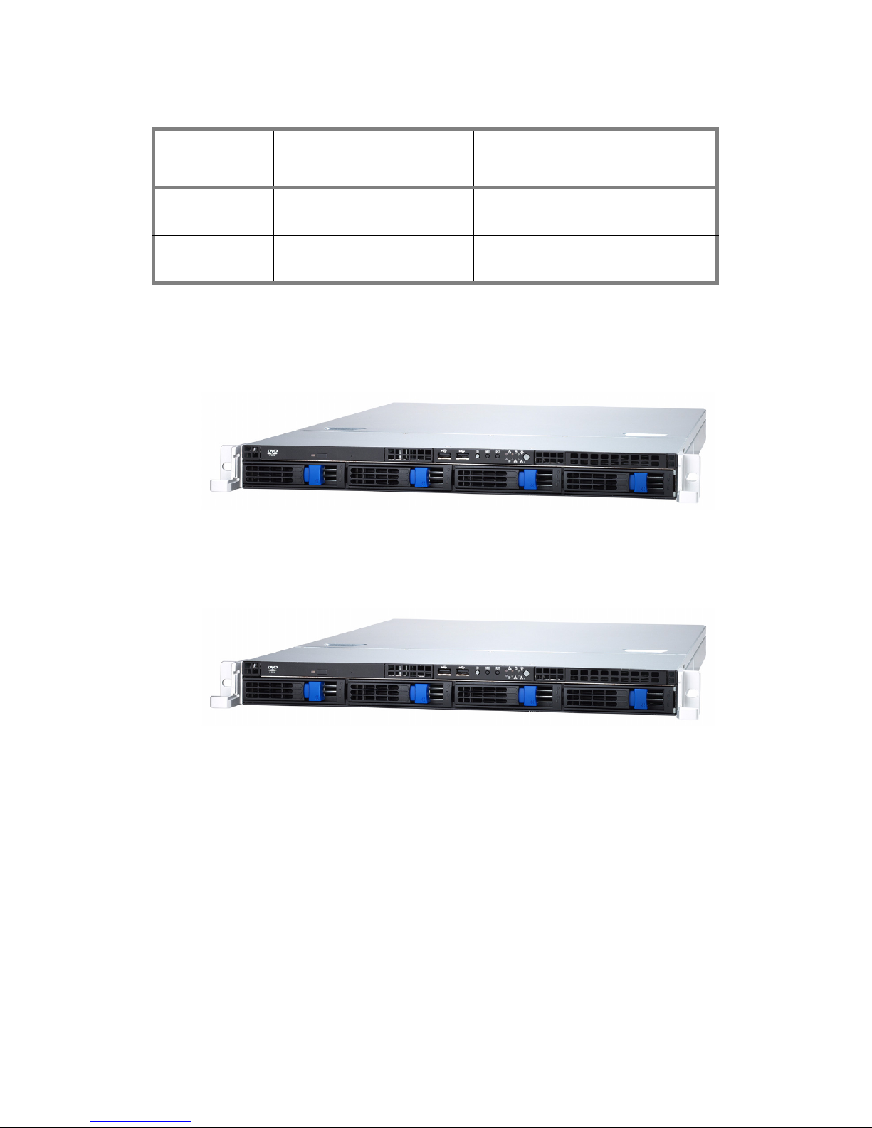
1.2 Product Models
B2932G24W4H
B2932G24V4H
Model HDD Bays
HDD
Supported
HDD
Backplane
Motherboard
B2932G24W4H
Removable,
4 HDDs
SAS/SATA
4-port
SAS/SATA
S2932WG2NR
B2932G24V4H
Removable,
4 HDDs
SATA
4-port
SAS/SATA
S2932WG2NR-L-B

Chapter 1: Overview 3
1.3 Features
Enclosure
• Industry 19” rack-mountable 1U
chassis
• Storage bay
– (1) slim CD-ROM bay
– (4) 3.5” HDD bays
• Dimension:
D 25.4 x W 17.2 x H 1.72 inch
(645x436x43.6mm)
Processors
• Dual 1207-pin ZIF L1 sockets
• Supports up to two AMD Opteron
TM
2000/8000 series processors
Chipset
• nVIDIA nForce Pro 3600
• NEC nPD720400
• SMSC DME5017
• LSI 1068E
Memory
• Sixteen (16) 240-pin DDRII DIMM
sockets (8 on CPU1 and 8 on
CPU2).
• Supports up to 64GB of Registered
of DDRII 667/553/400 memory
Expansion Slots
• One (1) x8 PCI-E with riser (preinstalled)
Back I/O Ports
• One (1) PS/2 Keyboard and one (1)
mouse ports
• One (1) 9-pin UART Serial port
• One 15-pin VGA port
• Two USB 2.0 ports
• Two RJ45 10/100/1000 Base-T port
w/ activity LED
Front Panel Features
•I/O
– (2) USB 2.0 ports
•LED indicators
– Power LED
– (2) LAN LEDs
– HDD active LED
– Warning LED
–ID LED
•Switches
– Power switch
– NMI switch
– Reset switch
– ID switch
Storage
• Model B2932G24V4H
– Serial ATA II Host controllers
embedded
– Supports six (6) serial ports run-
ning at 3.0Gb/s
– NV RAID 0, 1, 0+1, 5, and JBOD
support
• Model B2932G24W4H
– LSI 1068E SAS controller
– Supports eight (8) SAS ports run-
ning at 3.0Gb/s
– NV RAID 0, 1 and JBOD support
Networking
• lTwo 10/100/1000 Base-T LAN
(nForce Pro 3600 integrated MAC
with Marvell 88E1121 Gigabit Ethernet PHY)
Video
• ATI® ES1000TM PCI graphics controller
• 32MB DDR Frame Buffer of video
memory
Motherboard
• B2932G24V4H
– TYAN Thunder n3600M
2932G2NR-L-B
• B2932G24W4H
– TYAN Thunder n3600M
2932GWG2NR
• E-ATX footprint (13” x 12”)
BIOS
• AMI BIOS on 8Mbit LPC Flash ROM
• Supports ACPI 2.0
• PnP, DMI2.0, WfM2.0 power management
Power Supply
• EPS 12V, 1U, 650W/600W High
efficiency PSU
• 100V~240V AC input

4 Chapter 1: Overview
Server Management
• Automatic fan speed control
• Support Tyan Server Management
(TSM)
• Option TYAN SMDC M3291, IPMI
v2.0 compliant remote server management kit
System Cooling
• (2) 40*40*56mm 15000rpm heavyduty fans with fan speed monitor/control
• (3) 40*40*28mm 15000rpm heavyduty fans with fan speed monitor/control
• (2)Passive CPU Heatsink
Regulatory
• FCC Class B (Declaration of Conformity)
• CE (Declaration of Conformity)
Environment Temperature
• Operating temperature (5oC~35oC)
• Non-operating temperature (-40
o
C~
70
o
C)
Chapter 1: Overview 5
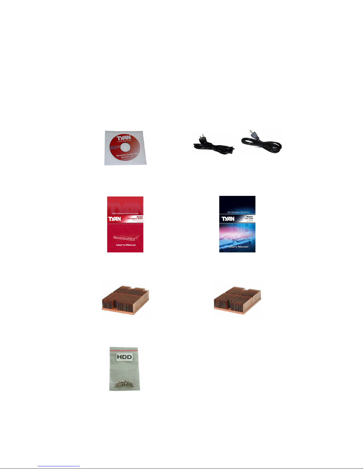
1.4 Unpacking
1.4.1 Accessories
If any items are missing or appear damaged, contact your
retailer or browse to TYAN’s Web site for service:
http://www.tyan.com.
The Web site also provides information on other TYAN products, plus FAQs, compatibility lists, BIOS settings, and more.
1 x Tyan driver CD
Power Cords
Left to right: Europe, US
HDD Screws
Mainboard ManualBarebone Manual
CPU1 Heatsink
CPU2 Heatsink
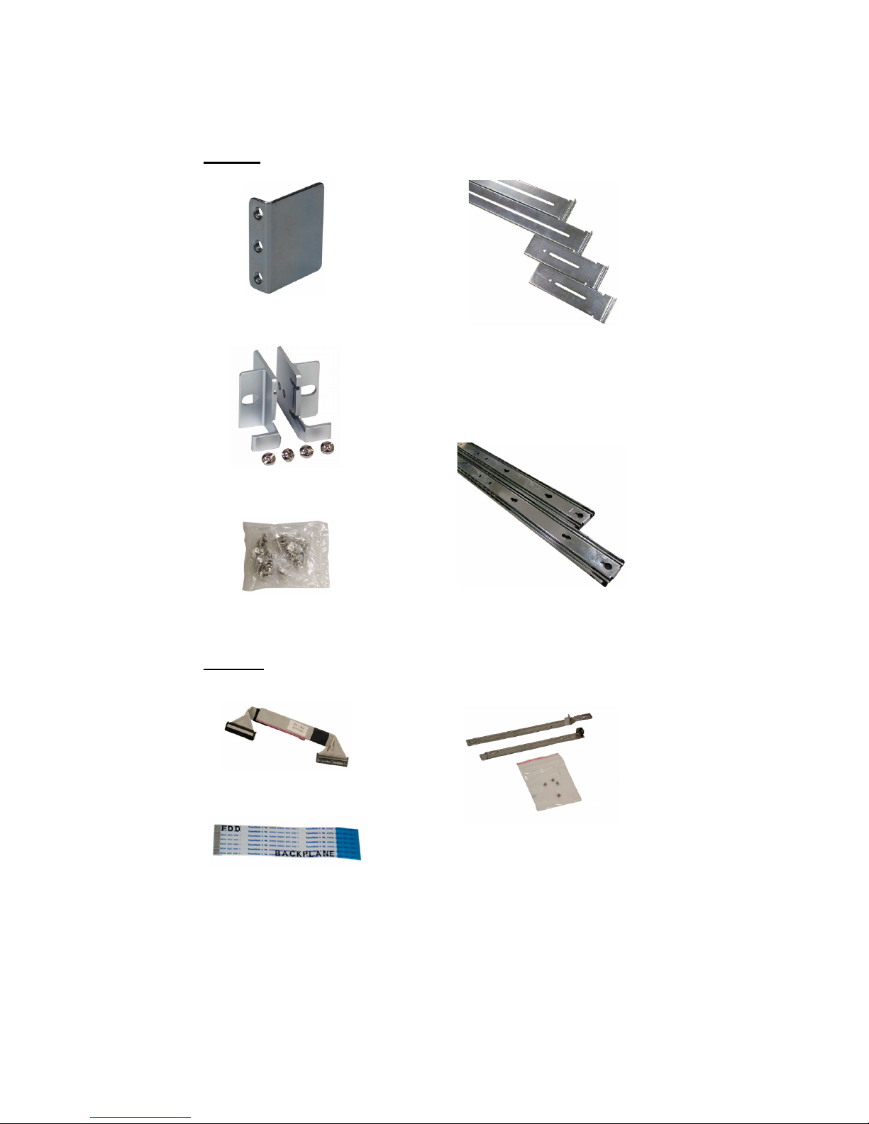
6 Chapter 1: Overview
Mounting Ears & Screws
Rail Kit
Mounting Bracket x 4
Sliding Brackets
Front L-Bracket x 2
Rear L-Bracket x 2
Screws Kit
Rear
Front
Sliding Rails x 2
FDD Kit
FDD Cable
FDD Backplane Cable
FDD Installing Rails & Screws
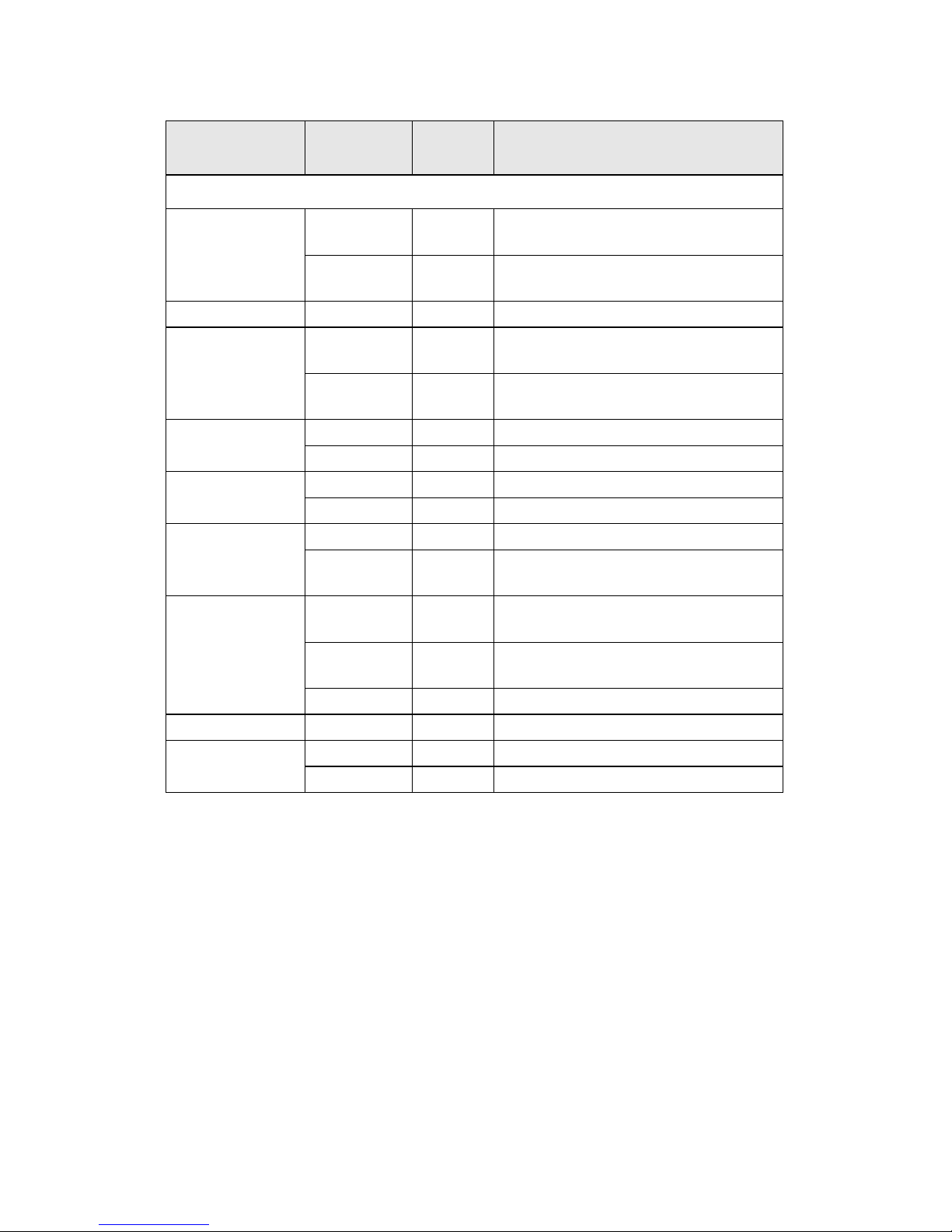
Chapter 1: Overview 7
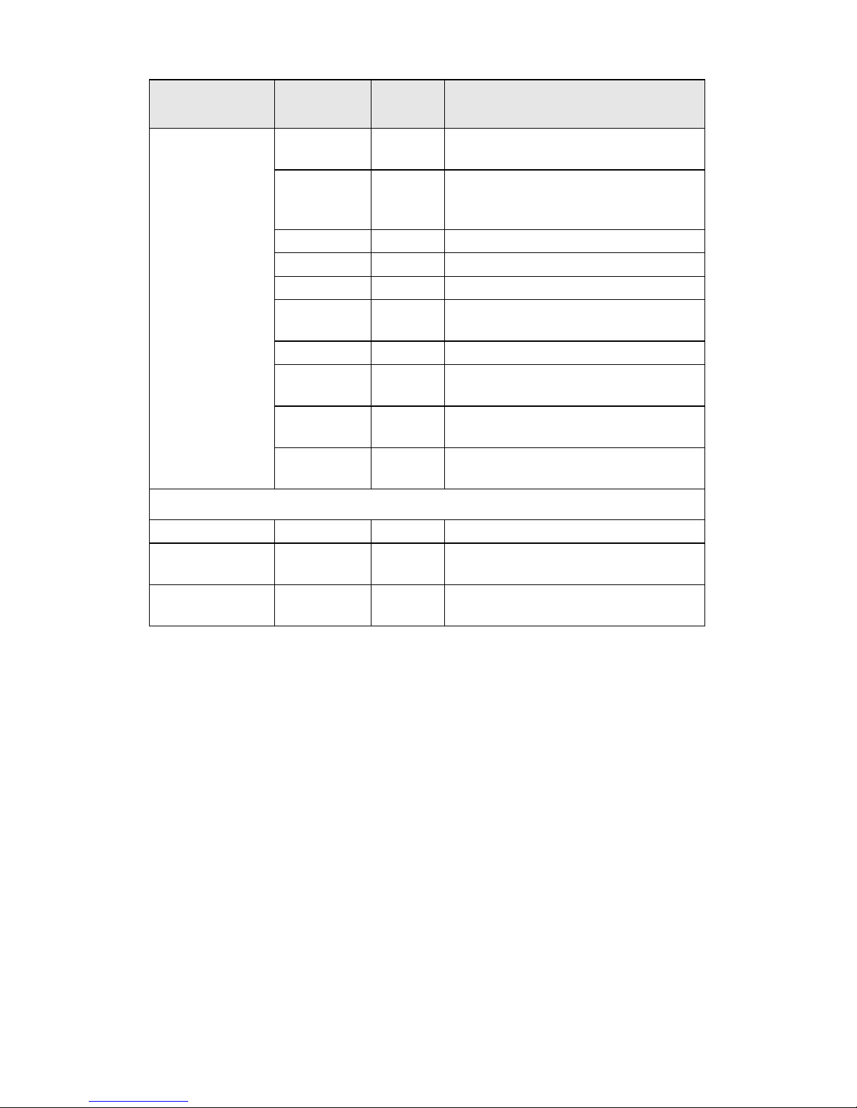
1.4.2 FRU Parts
Item
Model
Number
Quantity Description
Standard Parts
Motherboard
S2932G2NR
-L-B
1
TF-Motherboard Tyan S2932G2NR-LB(B2932G24V4H SKU)
S2932WG2
NR
1
TF-Motherboard Tyan S2932WG2NR
(B2932G24W4H SKU)
Chassis Unit CCHA-0030 1 TF-CHASSIS UNIT;GT24
Power Supply
CPSU-0112 1
TF-Delta 650W TDPS -650CB C 1U
PSU
CPSU-0260 1
TF-Delta 600W TDPS -600CB 1U
PSU
FAN
CFAN-0066 2 TF-Fan Assy; SanyoDenki 40x40x56
CFAN-0171 3 TF-Fan Assy; Sunon 40x40x28
Heat Sink &
Cooler
CHSB-0053 1 TF-Heatsink CPUO
CHSK-0052 1 TF-Heatsink CPU1
Peripheral Drives
& Parts
CDVD-0020 1 TF-DVD DRIVE; DV-28E-R93,TEAC
CPCA-0230 1
TF-CD-ROM Adapter board with
screw
Backplane
M1208 1
TF-PWA;PWA-GT24-M1208,
SATA/SAS BD
M1012-RS 1
TF-Front Panel Adaptor Board,
M1012-RS
M1003-RS 1 TF-LED Board, M1003-RS
Riser Card M2083-RS 1 TF-PCI-E Riser Card M2083-RS
Rack Mounting
Parts
CRAL-0031 1 TF-RAIL ASSY KIT;24",GT24
CEAR-0050 1 TF-Mounting Ear Kit, for GT20/GT24
8 Chapter 1: Overview
Cable Set
CCBL-0326 4
TF-SATA data cable, L=250mm
HS/180-HS/180
CCBL-0340 1
TF-Front panel Control Board Cable
HS2*14Pins/HS2*14 L=250mm(Flat
Cable)
CCBL-0409 1 TF-TYFP I Cable
CCBL-0419 1 TF-TYFP II Cable
CCBL-0433 1 TF-CD-ROM ATA66 FLAT CABLE
CCBL-0420 1
TF-CD-ROM Power cable S4P/S4P
L=80mm
CCBL-0652 1 TF-FAN CABLE L=160mm
CCBL-0493 1
TF- SAS HDD Fail Cable
(B2932G24W4H SKU)
CCBL-0310 1
TF-PWR CORD; US, 125V,
18AWGX3C
CCBL-0300 1
TF-PWR CORD; EU, 250V, H05VVFX3C
Optional Parts
Riser Card M2061 1 TF-PCI-E Riser Card M2061
LCD Module CLCM-0040 1
LCD module kit for GT series 1U
chassis
Chassis Front
Bezel
CFBZ-0070 1
Front bezel assembly for GT series 1U
chassis
Item
Model
Number
Quantity Description
Chapter 1: Overview 9
1.5 About the Product
This section contains the hardware diagrams and a block diagram of the GT24 system.
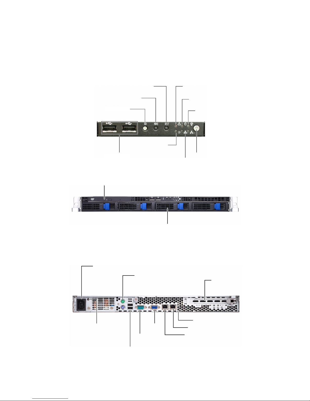
1.5.1 System Front View
1.5.2 System Rear View
HDD activity LED
Power switch
Power LED
Reset switch
USB ports
Warning LED
2 x LAN LEDs
ID Switch
NMI switch
ID LED
DVD-ROM Drive
Hard Drive Bay x 4
Power Supply
Socket
PS/2 Mouse/Keyboard Ports
Serial Port
VGA Port
LAN Port (NIC1)
PCI-E Slot
ID LED
LAN Port (NIC2)
LAN Port (NIC3)
Power Supply LED
2 USB ports

10 Chapter 1: Overview
1.5.3 LED Definition
Front Panel
LED Color State Description
Power Green
OFF
ON
OFF
Power ON
Power OFF
HDD Activity Amber
OFF
Random Blinking
OFF
HDD access activity
No disk activity
LAN1/LAN2 Activity Green
Green
OFF
ON
Blinking
OFF
LAN linked
LAN accessing
No LAN linked
Warning Red
OFF
ON
OFF
Fan fails / Abnormal shut
down
Normal
ID LED Blue
OFF
ON
OFF
System is identified
System is not identified
Hot Swappable HDD
Tray Power LED
Green
OFF
ON
OFF
Power connected
Power disconnected
Hot Swappable SATA
HDD Access LED
Amber
OFF
Random Blinking
OFF
HDD access activity
No disk activity
Hot Swappable SAS
HDD Access LED
Amber
Amber
OFF
ON
Random Blinking
OFF
HDD ready
HDD access activity
HDD not ready

Chapter 1: Overview 11
Rear I/O LED
LED Color State Description
LAN1/LAN2 Linkage/ Activity (Left Side)
Green
Green
OFF
ON
Blinking
OFF
10Mb/100Mb/1000Mb
linked
10Mb/100Mb/1000Mb
activity
No LAN linked and activity
LAN1/LAN2 Linkage/ Activity (Right Side)
Yellow 1 Blinking
2 Blinking
3 Blinking
OFF
10Mb mode
100Mb mode
1000Mb mode
NO LAN linked and activity
Note: In 10 Mbps, the Right LED blinks yellow once in repeat and continuous action.
In 100 Mbps, the Right LED blinks yellow twice in repeat and continuous action.
So does the condition in 1000 Mbps.
ID LED Blue
OFF
ON
OFF
System is identified
System is not identified
Delta Power
Supply LED
Green
Green
Amber
Amber
OFF
ON
1Hz Blinking
ON
1Hz Blinking
OFF
Output ON and OK
AC present/Only 5Vsb ON
Power supply critical event
causing a shutdown:
failure, OCP, OVP, fan fail
Power supply warning
event where the power
supply continues to
operate: high temp., high
power, high current, slow
fan
No AC power
12 Chapter 1: Overview
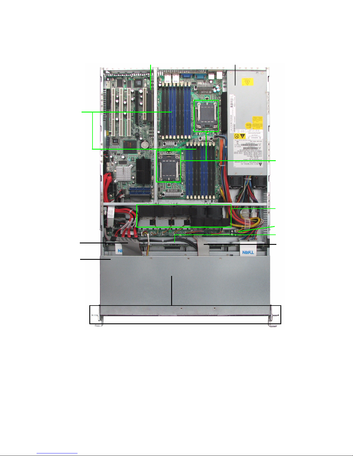
1.5.4 System Internal View
B2932G24W4H
8
10
9
3
4
5
6
7
1. PCI-Slot (with riser card
M2083)
2. EPS 12V Power Supply
3. CPU Sockets
4. System Fans (Top-Right to
left: FAN1, FAN2, FAN3,
FAN4, FAN5; Bottom-Right to
left: FAN6, FAN7)
5. Adapter Board
6. SAS/SATA Backplane
7. LED Control Board Cable
8. Four SATA HDDs
9. Slim DVD-ROM
10. DVD-ROM Cable
11. Memory Slots
11
1
2
FAN5 FAN4 FAN3 FAN2 FAN1
FAN7 FAN6
Chapter 1: Overview 13
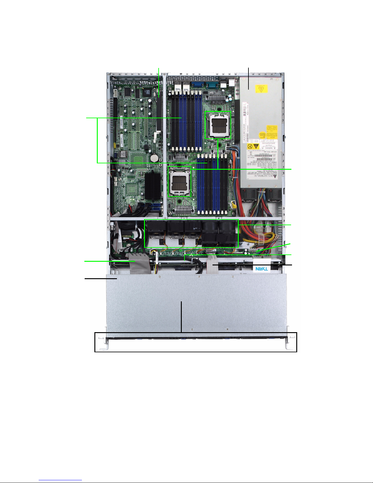
B2932G24V4H
8
10
9
3
4
5
6
7
1. PCI-Slot (with riser card
M2083)
2. EPS 12V Power Supply
3. CPU Sockets
4. System Fans (Top-Right to
left: FAN1, FAN2, FAN3,
FAN4, FAN5; Bottom-Right to
left: FAN6, FAN7)
5. Adapter Board
6. SAS/SATA Backplane
7. LED Control Board Cable
8. Four SATA HDDs
9. Slim DVD-ROM
10. DVD-ROM Cable
11. Memory Slots
11
1
2
FAN5 FAN4 FAN3 FAN2 FAN1
FAN7 FAN6
14 Chapter 1: Overview
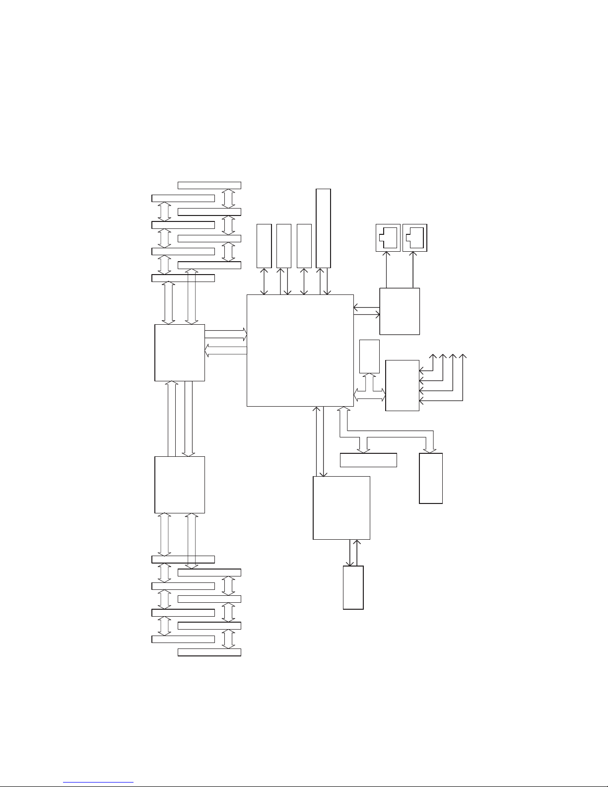
1.5.5 GT24-B2932 System Block Diagram
DDR2 SDRAM 7
DDR2 SDRAM 5
DDR2 SDRAM 3
DDR2 SDRAM 1
DDR2 SDRAM 6
DDR2 SDRAM 4
DDR2 SDRAM 2
Channel A
DDR2 SDRAM
Interface
16 x 16
HyperTransport
16 x 16
HyperTransport
AMD Socket F
Processor
Secondary CPU
CPU2
DDR2 SDRAM
Interface
Channel B
Channel A
LPC
PCI Bus
DDR2 SDRAM
Interface
DDR2 SDRAM
Interface
Channel B
DDR2 SDRAM 0
DDR2 SDRAM 0
DDR2 SDRAM 2
DDR2 SDRAM 4
DDR2 SDRAM 6
DDR2 SDRAM 1
DDR2 SDRAM 3
DDR2 SDRAM 5
DDR2 SDRAM 7
L1
AMD Socket F
Processor
Primary CPU
CPU1
L1
L0
RegisteredRegistered
MCP55 Pro
SAS1068E
LSI
SAS * 8
USB * 4
IDE * 1
SATA * 4
PCI-E X8 (X16 Slot)
PCI-Express X8
PCI 32/33
Marve11
88E1121
RJ45
GBLAN
RGMII
RJ45
GBLAN
PCI slot
BIOS
KB/MS
FLOPPY
COM1
COM2
Super IO
SCH5017
VGA
ATI ES1000
B2932 G24 W4H
SKU Only

Chapter 1: Overview 15
1.5.6 S2932 Board Parts, Jumpers, and Connectors
J64 Front Panel Header
J18 IPMB Pin Header J39/J63 TYAN Front Panel 2 Connector
(for Barebone)
J17 SMDC Connector J38 LCM Pin Header (for Barebone)
J41 Front Panel USB2.0 Connector J65 SGPIO Header (for Barebone)
J8 COM Port Pin Header J66 SAS Fault LED Pin Header
(for Barebone)
HDDLED+
1 2
PWR LED+
HDDLED-
3 4
PWR LED-
Reset Switch
5 6
Power Switch
Reset Switch
7 8
Power Switch
NMI
9 10
Warning LED+
NMI
11 12
Warning LED-
5Vsb
13 14
Key
SMBus Data
15 16
GND
SMBus Clock
17 18
Chassis Intr#
JP7
- Clear CMOS Jumper
Pin 1-2 closed: Normal (Default)
Pin 2-3 closed: Clear CMOS
JP1/JP2
- PCI-X1/PCI-X2 Speed Setting
Jumper
Pin 1-2 closed: 133MHz
Pin 2-3 closed: 100MHz
JP3/JP4
- ASF2.0/SMDC Select Jumper
Pin 1-2 closed: ASF2.0 (Default)
Pin 2-3 closed: SMDC
JP5
- VGA Enable/Disable Jumper
Pin 1-2 closed: Enable (Default)
Pin 2-3 closed: Disable
JP6
- SAS Enable/Disable Jumper
Pin 1-2 closed: Enable (Default)
Pin 2-3 closed: Disable
Power Supply
The S2932 is EPS12V compatible.
3 power connectors: EPS12V
(24-pin + 8-pin + 4-pin)
Check User’s Manual for details

16 Chapter 1: Overview

Chapter 2: Setting Up 17
Chapter 2: Setting Up
2.0.1 Before You Begin
This chapter explains how to install the CPU, CPU heatsink,
memory modules, and hard drives. Instructions on inserting a
PCI-E card are also given.
Take note of the precautions mentioned in this section when
installing your system.
2.0.2 Work Area
Make sure you have a stable, clean working environment.
Dust and dirt can get into components and cause malfunctions. Use containers to keep small components separated.
Putting all small components in separate containers prevents
them from becoming lost. Adequate lighting and proper tools
can prevent you from accidentally damaging the internal
components.
2.0.3 Tools
The following procedures require only a few tools, including
the following:
• A cross head (Phillips) screwdriver
• A grounding strap or an anti-static pad
Most of the electrical and mechanical connections can be disconnected using your fingers. It is recommended that you do
not use needle-nosed pliers to remove connectors as these
can damage the soft metal or plastic parts of the connectors.
 Loading...