

TYAN Transport GX15 B2723T15, Transport GX15 B2723T15M, B2723T15, Transport GX15, B2723T15M User Manual
Page 1

B2723T15 /// Transport GX15
B2723T15M
Revision 1.0
Copyright © TYAN Computer Corporation, 2002-2003. All rights reserved. No
part of this manual may be reproduced or translated without prior written
consent from TYAN Computer Corp.
All registered and unregistered trademarks and company names contained in
this manual are property of their respective owners including, but not limited to
the following.
TYAN, Tiger i7501 S2723, Transport B2723T15, Tran sport B2723T15M,
Transport GX15 are trademarks of TYAN Computer Corpo ration.
Intel, Xeon and combinations thereof are trademarks of Intel Corporation.
AMI, AMIBIOS are trademarks of AMI Software Incorporated.
Microsoft, Windows are trademarks of Microsoft Corporation..
QLogic, Zircon, and combinations thereof are trademarks of QLogic
Corporation.
IBM, PC, AT, PS/2 are trademarks of IBM Corporation.
Winbond is a trademark of Winbond Electronics Corporation.
Portable Document Format (PDF) is a trademark of Adobe Corporation.
Information contained in this document is furnished by TYAN Computer
Corporation and has been reviewed for accuracy and reliability prior to printing.
TYAN assumes no liability whatsoever, and disclaims any express or implied
warranty, relating to sale and/or use of TYAN products including liability or
warranties relating to fitness for a particular purpose or merchantability. TYAN
retains the right to make changes to product descriptions and/or specifications
at any time, without notice. In no event will TYAN be held liable for any direct or
indirect, incidental or consequential damage, loss of use, loss of data or other
malady resulting from errors or inaccuracies of information contained in this
document.
1
http://www.tyan.com
Page 2

Table of Contents
Before you begin…
Chapter 1: Introduction
1.1 Congratulations
1.2 Hardware Specifications
1.3 Front View
1.4 Top View
Chapter 2: Hardware Installation
2.0 Installation Procedures
2.1 Opening the Chassis
2.2 Installing HDD
2.3 Installing Processor(s) and
heatsink(s)
2.4 Installing Add-on PCI Card
2.5 Installing Memory Modules
2.6 Installing Vent Duct
2.7 Finishing up
Chapter 3: Installing Into A Cabinet
or Telco Rack
3.0 Before you begin
3.1 Installing single system into a
19” cabinet
Chapter 4: Server Management Daughter
Card ( SMDC)
4.1 Summary
4.2 Features at a glance
4.3 Jumper setting
4.4 Specification
4.5 SMDC Features
4.6 Tyan System Operator (TSO)
summary
Appendix
Safety Document of system
Safety Document of SMDC
...……………………………………..Page 3
...……………………………………..Page 4
...……………………………………..Page 4
..….…………………………………..Page 5
...……………………………………..Page 6
.....………………………………… ..Page 7
...………………………………… ..Page 8
.…………………………………… ..Page 8
.…………………………………… ..Page 9
...………………………………… ..Page 10
...………………………………… ..Page 11
...………………………………… ..Page 12
...………………………………… ..Page 13
....…………………………………..Page 14
.....………………………………….Page 15
..……………………………………Page 16
..…..………………………………..Page 16
…...…..…………………………….Page 17
..………………………………..Page 18
….….….……..…………………….Page 18
..……..……………………………..Page 19
...……………………………………Page 20
…...…………………………………Page 20
….…………………………………..Page 25
…..………………………………….Page 31
…..………………………………….Page 32
.….………………………………….Page 32
.….………………………………….Page 33
2
http://www.tyan.com
Page 3
Before you begin…
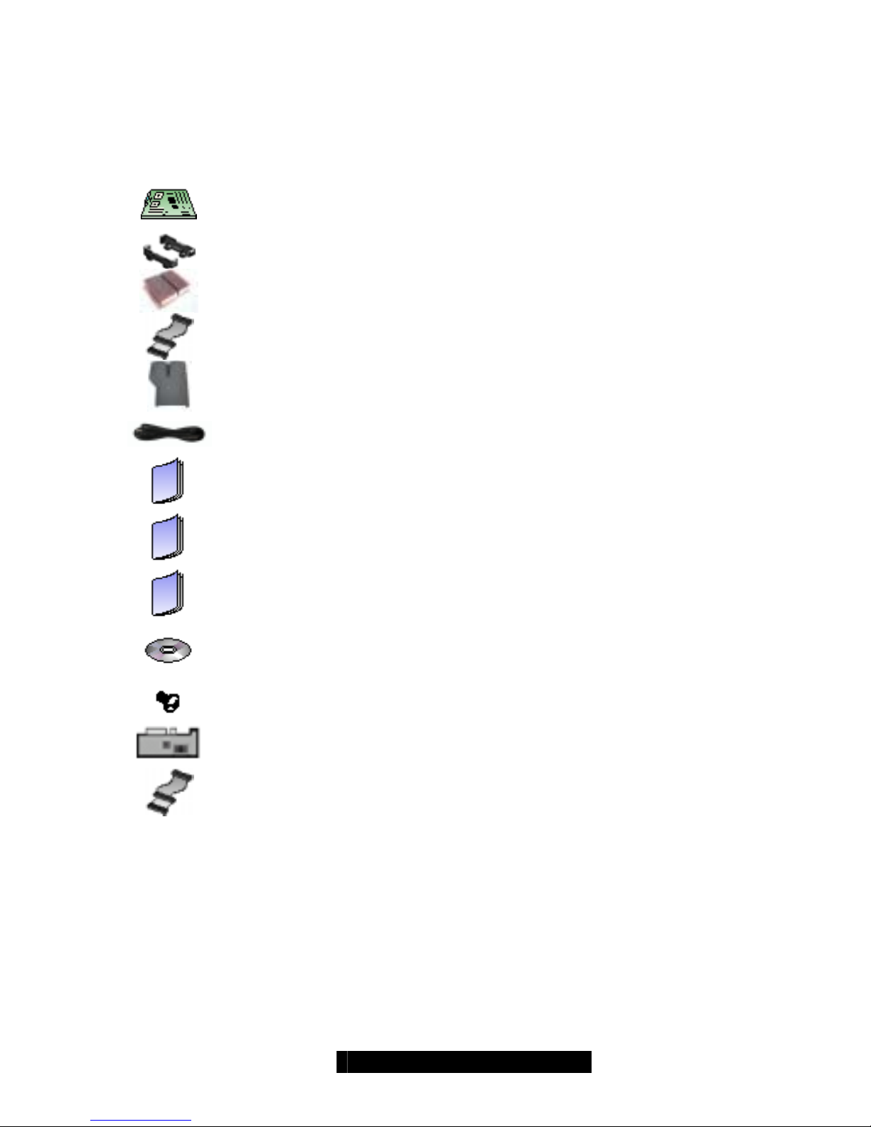
Check the box contents!
The barebone system package should contain the followin g:
1 x Tiger i7501 (S2723) motherboard (preinstalled)
2 sets x CPU retentions and clips
2 x Xeon Heatsink
1 x ATA 100 cable for HDD (pre-installed)
1 x Vent duct
2 x power cords (1 x compatible for standard US voltage, 1 x
compatible for standard German voltage)
1 x Tiger i7501 (S2723) User’s Manual
1 x Transport B2723T15/B2723T15M User’s Manual
1 x Tiger i7501 (S2723) Quick Reference
1 x TYAN driver CD
1 x screw
1x Tyan M3289 SMDC (optional item for B2723T15M)
1x 50-pin SMDC cable (optional item for B2723T15M)
If any of these items are missing, please contact your vendor/dealer for replacement
before continuing with the installation process.
3
http://www.tyan.com
Page 4

Chapter 1: Introduction
1.1 – Congratulations!
Thank you for choosing the TYAN B2723T15/B2723T15M, the most compact Dual
Intel
®
Xeon processor platform for flexibility and productivit y. Based on Intel’s E7501
chipset, this powerful system is Hyper-Threading ready - utilizing onbo ard resources
so that a second thread of data can be processed in a single processor. Special
features of this system include IPMI Server Management, PCI-X support, one
10/100/1000 and one 10/100 Ethernet ports and onboard video.
Remember to visit TYAN’s Website at http://www.tyan.com
. There you can find
information on all of TYAN’s products with FAQs, distributors list and BIOS setting
explanations.
4
http://www.tyan.com
Page 5

1.2 – Hardware Specifications
Form Factor:
• Optimized 1U form factor
• 14.5” inch in depth
• Dimensions (W x H x D):
482.6mm x 44mm x368.3mm
(19” x 1.73” x 14.5”)
Drive bays:
• 1 x internal 3.5” drive bay
Cooling Fans:
• 3 pcs 40x40x28 mm system fans with
tachometer monitoring
• Specially-designed CPU fan duct
Switch and LED Indicators:
• 1 x power switch
• 1 x reset switch
• 1 x power LED
• 1 x HDD LED
PSU:
• 300W EPS12V PSU (w/ active PFC)
System board:
• Tyan Tiger i7501 (S2723GNN)
Processor
• Dual mPG604 ZIF Socket
• Supports up to 2 x Intel
®
XEON
processors with 512KB of integrated L2
cache
• Supports processor speed up to 2.8GHz
• Front-Side Bus support for 533MHz
Chipset
• Intel
®
E7501 server chipset
• MCH + ICH3 + P64H2 + FWH
I/O Expansion
• 1x PCI-X expansion slot on riser card
Memory
• Four 184-pin 2.5-Volt DDR DIMM
sockets
• Supports up to 8GB of Registered DDR
RAM
• Supports only Registered ECC type
memory modules
Integrated LAN
• Two RJ-45 LAN Connectors with LEDs
• One 10/100
• One 10/100/1000
Server Management Daughter Card
(Option)
• Tailored for IPMI highest 1.5
specifications
• Supports flexible Windows and Linux
based
Management Solution
• Supports remote Power on/off and reset
support (IPMI-over-LAN)
BIOS
• AMI BIOS 8.0 on 4Mbit Flash ROM
• LAN remote boot (PXE) and SMBIOS
v2.3 support
• BIOS Boot Specification v3.1(BBS)
support
• Auto configuration of IDE hard disk
types
Regulatory
• FCC Class A certified
• European CE certified
(Declaration of Conformity)
Packing information
• Barebone weight: 11 kg
• Complete system weight: 11.5 kg
TYAN reserves the right to add support
or discontinue support for any OS
without notice.
5
http://www.tyan.com
Page 6
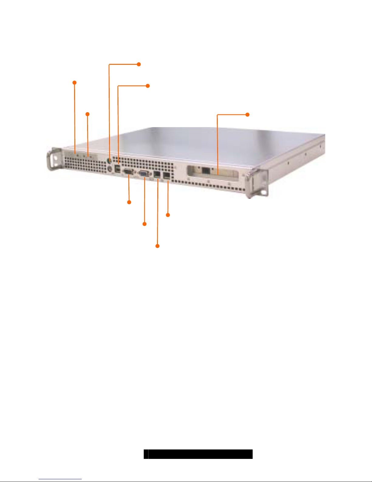
1.3 – Front View
Powe
r
/HDD
LEDs
Power/
Reset
Switches
PS/2 Mouse and Keyboard
Double-deck USB 1.1 Port
A
dd-on PCI
Expansion Slot
Fast Ethernet w/ LED
VGA Port
Gigabit Ethernet w/ LED
6
http://www.tyan.com
Page 7

1.4– Top View
Cooling Fans
CPU 2
EPS 12V
PSU
CPU 1
HDD
Riser card
Memory
Slots
SMDC
( Server
Management
Daughter Card)
7
http://www.tyan.com
Page 8

Chapter 2: Hardware Installation
2.0 Introduction
You are now ready to install your system.
The first thing you should do is read this user’s manual. It contains important
information that will make installation and setup much easier. Here are some
precautions you should take when installing your system:
(1) Ground yourself properly before removing the top cover of the system. Unplug
the power from your computer power supply and then touch a safel y grounded
object to release static charge (i.e. power supply case). For the safest
conditions, Tyan recommends wearing a static safety wrist strap.
(2) Avoid touching the motherboard components, IC chips, connectors, memory
modules, and leads.
(3) Motherboard is pre-installed in the system, if, under any circumstances, it is
removed from the system, place the motherboard on a grounded antistatic
surface.
(4) Inspect the board and system for damage.
The following pages include details on how to install the processor, memory, disk drive
and cables.
NOTE
DO NOT APPLY POWER TO THE SYSTEM IF ANY PART OF THE
SYSTEM COMPONENTS HAS BEEN DAMAGED
8
http://www.tyan.com
Page 9
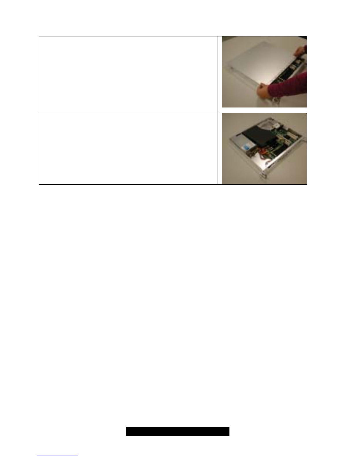
2.1 Opening the chassis
2.1.1 Push the top cover toward back.
2.1.2 Lift up the top cover and remove it
from the chassis.
2.1.3 Top cover removed.
9
http://www.tyan.com
Page 10
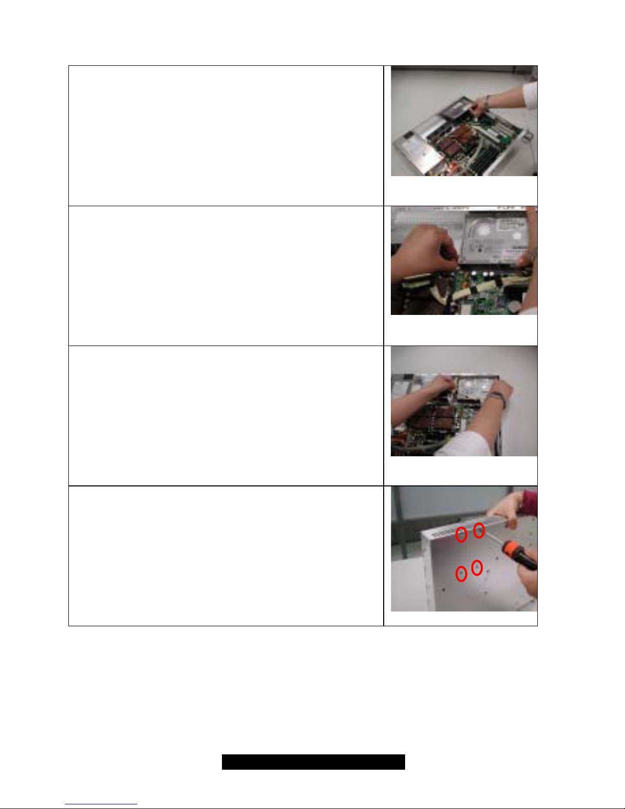
2.2 Installing HDD
2.2.1 Slide the HDD into place.
2.2.2 Connect the Power cable to HDD.
2.2.3 Connect ATA cable to HDD.
Note: ATA cable is pre-connected to M/B (J23).
2.2.4 Secure the drive with 4 screws from
the bottom of the chassis.
10
http://www.tyan.com
Page 11

2.3 Installing Processor (s) and Heatsink(s)
2.3.1 Lift the lever on the CPU socket until
it is approximately 130
o
or as far
back as possible to the socket.
2.3.2 Align the processor with the socket.
There are keys underneath the
processor just like on memory
modules to ensure that they insert
the correct way.
2.3.3 Seat the processor firmly into the
socket by gently pressing down until
the processor sits flush with the
socket.
2.3.4 Place the socket lever back down
until it snaps into place.
2.3.5 Your processor is installed
2.3.6 Repeat these steps for any
additional processors if you are
using more than one processor.
2.3.7 Seat heatsinks between brackets
(pre-installed) on the processor and
attach heatsinks clips to secure.
11
http://www.tyan.com
Page 12

2.4 – Installing Add-on PCI Card
2.4.1 Loosen the screw and remove PCI slot
cover.
2.4.2 Plug your PCI/PCI-X add-on card into
the PCI socket slot on the riser card.
2.4.3 Secure Add-on card by tightening the
screw from the side.
12
http://www.tyan.com
Page 13

2.5 Installing Memory Modules
Note: Please make sure to read through M/B User’s Manual before your
start installing memory modules.
2.5.1 Insert the DIMM modules into the
memory slots, starting with memory
slot B1+B2 or A1+A2.
2.5.2 Press down on the memory modules
until it locks into place.
2.5.3 The B2723T15/B2723T15M requires
that memory modules be installed IN
PAIRS. Please refer to S2723/Tiger
i7501 M/B User’s Manual page
16~18 for exact details.
2.5.4 To ensure thermal performance,
LOW PROFILE memory modules are
recommended.
13
http://www.tyan.com
Page 14

2.6 Installing Vent Duct
2.6.1 Attach the vent duct on the CPU area.
2.6.2 Place the vent duct on the top of CPU
area, in between the capacitors as
shown in pictures.
14
http://www.tyan.com
Page 15

2.7 Finishing Up
2.7.1 Put the top cover back on and fasten
the thumb screws in the back of the
chassis.
Congratulations on making it this far! You’re finished setting up the har dware aspect of
your computer. Before closing up your chassis, make sure that all cables and wires are
connected properly, especially IDE cables and most importantly, jumpers. You may
have difficulty powering on your system if the motherboard jumpers are not set
correctly. For detailed M/B jumper settings, please refer to S2723/ Tiger i7501 M/B
user’s manual.
In the rare circumstance that you have experienced difficulty, you can find help by
asking your vendor for assistance. If they are not available for assistance, please find
setup information and documentation online at our website or by calling your vend or’s
support line.
15
http://www.tyan.com
Page 16

Chapter 3: Installing Into A 19” Cabinet/ Telco Rack
3.0 Before you begin ….
The system is both light and easy-to-install into cabinets and racks, so we suggest that
you use the mounting brackets (on both sides of the system) to directly attach and
secure this rackmount system.
Should you still prefer to have rails in order to slide the system in and out from the
cabinet, you may purchase a separate rail kit from Tyan. Please contact your local
Tyan office for more details.
Note:
1. When installing two systems back-to-back, please choose:
a. 19” cabinet of 1000mm and above in depth.
b. 4-post telco rack (open-air rack).
16
http://www.tyan.com
Page 17

3.1 Installing system into a cabinet or telco rack
3.1.1 Place the system between the poles
inside the cabinet.
3.1.2 Secure the system to the desired
location using screws provided by
cabinet manufacturer.
3.1.3 Finished look.
17
http://www.tyan.com
Page 18

Chapter 4: Server Management Daughter Card / SMDC
(pre-installed in B2723T15M)
Warning:
DO NOT INSERT SMDC INTO ANY PCI SLOT.
4.1 – Summary
The Tyan Server Management Daughter Card (SMDC) is a powerful yet cost-efficient
solution for high-end server management hardware packages. The SMDC provides
remote system monitoring and control even when the operating system is absent or
simply fails, and empowers server boards with advanced industry standard features. It
effectively enables IT Managers to have remote and multi-interface access to monitor,
control, and diagnose activities.
The Tyan SMDC is powered by an intelligent controller known as the Baseboard
Management Control (BMC). The BMC is a standalone mini-CPU that runs on its own
Real Time Operating System (RTOS) to complete a variety of tasks. Backed by
QLogic’s reliable ARM7 technology, systems are consistently monitored and supp orted.
Unlike regular cards such as AGP cards, network cards or SCSI cards, the SMDC is
not a peripheral card that requires any hardware specific driver. As long as standby
power supports the system, the SMDC will monitor the system.
The Tyan SMDC provides many diverse methods to communicate with the hardware.
There is flexibility to choose among Keyboard Controller St yle (KCS), Block Transfer
(BT) style, Intelligent Platform Management Bus (IPMB), Emergency Management Port
(EMP) and standard IPMI-Over-LAN communication as defined in latest IPMI 1.5
specification. The Tyan SMDC is compatible with all IPMI-compliant software as well
as with the Tyan System Operator™ (TSO) software package. The SMDC hardware is
OS-dependent and is fully compatible with all major Operating Systems.
18
http://www.tyan.com
Page 19

4
.2 – Features at a Glance
Feature Description
BMC QLogic Zircon V2 based on ARM7 technology
IPMI Version 1.5 Spec
FRU “Field Replaceable Unit” Information Storage
SDR Sensor Data Record
SEL Sensor Event Log
GPIO “General Purpose Input and Output” lines for future expansion.
IPMB Intelligent Platform Management Bus
EMP Emergency Management Port
RTC Real Time Clock
IPMI-Over-LAN Remote sensor monitor, host control and system diagnose
Remote Host
Control
Power up, down, reset, power cycle or NMI through LAN port
Remote Sensor
Monitor
SMDC provides sensor information as long as BMC receives
enough operating power.
Remote
Diagnostic
SMDC allows for system diagnostic when the system is not in
operation (either intentionally or accidental ly) through remote IPMI
command execution.
BMC Firmware
Update
SMDC supports onboard update of the BMC firmware.
ASF Alert Standard Forum
TSO Tyan System Operator™
19
http://www.tyan.com
Page 20

4.3 – Jumper Setting
Label Header Type/Part Description Pin Layout
J1 HDR25X2_SVM_A SVM Edge
Connector A
Reserved
Pin 1 GND J10 HDR2 Zircon Firmware
Reset
Pin 2 BMC_RESET#
Pin 1 DCD
Pin 2 RXD
Pin 3 TXD
Pin 4 No Connection
Pin 5 GND
Pin 6 No Connection
Pin 7 RTS
Pin 8 CTS
Pin 9 RI
J28 HDR5X2 UART /
Emergency
Management Port
Pin 10 No Connection
Pin 1 SDA
Pin 2 GND
Pin 3 SCL
J41 HDR4X1 BMC Private I2C
Pin 4 5VSB
4.4 – Specifications
The following specifications are described below in detail.
Hardware Monitoring
Protocol and Standard
Auxiliary Communication Interface
Auxiliary SMBus / I
2
C buses
Teamed with other IPMB Devices (PMCs and EMCs)
Remote Monitor, Control and Diagnostics
Sensor Repository
System Event Log
Field Replaceable Unit Information Storage
Emergency Management Port Console
Real Time Clock
Upgrade firmware
Front Panel LED and Buzzer
“Always Ready”
TYAN System Operator ™ (TSO)
OEM Drivers
20
http://www.tyan.com
Page 21

Hardware Monitoring
The latest hardware from TYAN is equipped with Baseboard Management Controller
(BMC) from QLogic Zircon, which provides not only system monitoring but also remote
manageability. The BMC can always monitor the hard ware r egardless of how the
operating system is running. With the BMC onboard, any IPMI-compliant software can
monitor, control or diagnose the hardware locally, or from a remote site.
Protocol and Standard
• Intelligent Platform Mana gement Interface (IPMI)
• Remote Manageme nt and C ontrol Protocol (RMCP) for IPMI-Over-LAN
• Alert Standard Forum (ASF)
Auxiliary Communication Interface
Other standard devices that the SMDC communicates with:
• IPMB = Intelligent Platform Management Bus
• EMP = Emergency Management Port
• LAN = Local Area Network
Auxiliary SMBus / I
2
C buses
The SMDC provides 4 dedicated and independent buses for user expansion. A lot of
devices including Northbridge, Southbridge, Super I/O, Hardware Monitor, LAN
controller, etc. provide I
2
C communication. These I2C buses bridge the proper
communication between these devices.
Teaming with other IPMB Devices (PMCs and EMCs)
Numerous devices in the market already support IPMB communication. BMC
facilitates the control and management of these mentioned devices. PMC stands
for Peripheral Management Controller and EMC stands for Enclosure
Management Controller.
Depending on the overall set up of the system, the SMDC could initialize and
communicate with other PMC/EMC residing on the same IPMB bus. Simply connect
the devices to designated IPMB connector.
Examples of PMC/EMC Devices include:
• Satellite controller - SCSI RAID controller unit
• Power supply - power supply unit that has a hardware monitoring chip inside
21
http://www.tyan.com
Page 22

Remote Monitor, Control and Diagnostics
Sensor Monitor
• Voltage
• Temperature
• Tachometers
• Fan Speed Control / PWM
• Chassis Intrusion
Control Command Set
• Power Up
• Power Down
• System Reset
• System Power cycle
• System NMI
• Watchdog Timer
Diagnostic Command Set
• Power-Good Detection
• CPU Voltage Identification (CPU VID)
• ACPI State Detection
• Request Message Redirection through IPMB and ICMB
Sensor Repository
Detailed sensor information including sensor types and measuring units are available
on the Intel website regarding IPMI: www.intel.com.
System Event Log (SEL)
Complete history of system events such as POST events are stored and secured in
non-volatile memory. SEL records critical events when BMC detects a critical event
within the server. Certain pre-programmed actions may take place such as system
reboot or system shutdown.
Field Replaceable Unit Information Storage (FRU)
Chassis, Board, Product and other important service information are stored and
secured in an area generally known as FRU.
22
http://www.tyan.com
Page 23

Emergency Management Port Console (EMP)
The EMP console is a type of remote management method. The SMDC provides a
control console to designated serial port.
BMC firmware supports EMP console through RS232 as additional level of system
management. It communicates with remote station via VT100 emulation and
provides following functionalities with menu-driven user interface:
• Event Log Viewer/Maintenance
• FRU Viewer
• SDR Viewer
• Sensor Reading Viewer
• BMC firmware/IPMB controller firmware information
• System Power on/off, system, and BMC reset
* Header J28 on the SMDC provides a serial console that accesses BMC directly.
Use the Header-to-Serial connector (included) and a null modem cable (not included)
to hook up to the serial/COM port of any PC. Use HyperTerminal in Windows to view
the EMP console.
HyperTerminal™ Settings:
• Terminal Type: VT100 or ANSI
• Baud rate: 38400bps
• Parity: N-8-1
• Flow control: None
Real Time Clock (RTC)
SMDC maintains its own RTC for scheduling events and keeps it in sync with
system RTC
Upgrade firmware
The BMC supports Firmware Flash through IPMI firmware commands. The Firmware is
stored in boot block flash part. The boot block section code is normally programmed in
factory and it provides protection against accidental flash failure or power loss.
Front Panel LED and Buzzer (Optional)
In additional to standard BMC functionalities, BMC firmware controls Front Panel LED
and motherboard Buzzer for error warning and display.
23
http://www.tyan.com
Page 24

“Always Ready”
SMDC runs on stand-by power; all monitoring and alerting operations of BMC can
begin full operation by using only standby power.
Tyan System Operator™ (TSO)
TSO is a software tool created specifically for IPMI-compliant systems with SMDC. It
intends to provide IT managers the ability to monitor, control and diagnose their Tyan
server boards with ease and flexibility in a re mote control configuration. Consult Tyan
System Operator™ user manual for details.
OEM Drivers
Tyan may provide driver support for other third party software at request. Contact your
Tyan support representative for more details.
24
http://www.tyan.com
Page 25

4.5 SMDC Features
Note: If the administrating machine is running Windows 2000, please inst all Windows
2000 Service Pack 2 or above to correct a know issue with HyperTerminal.
The following examples are what you shoul d see on your screen after connecting the
necessary components to your SMDC and motherboard.
Note: If the following windows do not appear on your screen, press CTRL-L to refresh
the system.
When the window titled “COM1 Properties” appears, choose the following settings:
1. Select 38400 for Bits per second
2. Select 8 for Data bits
3. Select None for Parity
4. Select 1 for Stop bits
5. Select None for Flow control
6. Press OK
25
http://www.tyan.com
Page 26

Next, click on the Settings tab on the window titled “SMDC EMP Properties”.
1. Select Terminal keys under “Function, arrow, and ctrl keys act as”
2. Select Ctrl + H under “Backspace key sends”
3. Select Auto detect for Emulation
4. Type in ANSI for “Telnet terminal ID”
5. Select 500 for Backscroll buffer lines
6. Leave the box for “Play sound when connecting or disconnecting” unchecked
7. Press OK
26
http://www.tyan.com
Page 27

The ASCII Setup window will then appear.
1. Uncheck the “Wrap lines that exceed terminal width” option.
2. Enter 0 in the “Line delay” and “Character delay” options.
(EMP continued on the next page)
27
http://www.tyan.com
Page 28

(EMP continued)
The examples below depict what you see when in the EMC Main Menu. To check
and/or alter the current status of your system, you can select a specific category under
the Main Menu and access the specific settings there.
Keyboard Definitions
The table below shows how to navigate in the setup program using the keyboard.
Key Function
Tab Moves from one selection to the next
Left/Right Arrow Keys Change from one menu to the next
Up/Down Keys More between selections, go to
submenu
Enter Open highlighted section
Esc Go back to previous menu
Note: Remember to use CTRL-L to refresh the terminal screen if there is a display
problem.
28
http://www.tyan.com
Page 29

Note: Please open flash.exe on the TSO CD and follo w the directions on h ow to flash.
The file extensions end with .mhx and .bin.
29
http://www.tyan.com
Page 30

The example above shows an event log of your system’s activity since the last time the
log was cleared. Up to 512 possible event entries can be listed. These events stay
within the hardware until cleared by IPMI instructions.
The column under the State category shows you the condition of your running system.
The table below is a key of the possible conditions that your system can be in.
Status Description
Lwer_N_Crtcl Below Lower Non-Critical Threshold
Lwer_Crtcl Below Lower Critical Threshold
Lwer_N_Rcvbl Below Lower Non-Recoverable
Threshold
Uper_N_Crtcl Above Upper Non-Critical Threshold
Uper_Crtcl Above Upper Critical Threshold
Uper_N_Rcvbl Above Upper Non-Recoverable
Threshold
O.K. Sensor is running within Thresholds
30
http://www.tyan.com
Page 31

4.6 TYAN System Operator™ (TSO) Summary
TSO Summary
General Features
• Sensor Monitor Service
• System Control and Diagnose Panel
• System Up/Down/Power Cycle/NMI
• FRU Browser
• SDR Browser
• SEL Browser
• SNMP Architecture
• Watchdog Timer Activation/Deactivation
• Remote BIOS Flash
• Remote BMC Firmware Flash
Platform Support
Management Console
• Windows 2000/XP
• RedHat Linux 7.3
TSO Agent (Server Side)
• Windows 2000
• RedHat Linux 7.3
31
http://www.tyan.com
Page 32

Appendix 1: Safety document of Tyan B2723T15/B2723 T15M
Notice for the USA
Compliance Information Statement (Declaration of Conformity Procedure) DoC
FCC Part 15: This device complies with part 15 of the FCC Rules
Operation is subject to the following conditions:
1) This device may not cause harmful interference, and
2) This device must accept any interference received including interference that may
cause undesired operation. If this equipment does cause harmful interference to radio
or television reception, which can be determined by turning the equipment off and on,
the user is encouraged to try one or more of the following measures:
• Reorient or relocate the receiving antenna.
• Increase the separation between the equipment and the receiver.
• Plug the equipment into an outlet on a circuit different from that of the receiver.
• Consult the dealer on an experienced radio/television technician for help.
Notice for Canada
This apparatus complies with the Class B limits for radio interference as specified in the Canadian
Department of Communications Radio Interference Regulations. (Cet appareil est conforme aux
norms de Classe B d’interference radio tel que specifie par le Ministere Canadien des
Communications dans les reglements d’ineteference radio.)
Notice for Europe (CE Mark)
This product is in conformity with the Council Directive 89/336/EEC,
92/31/EEC (EMC).
CAUTION: Lithium battery included with this board. Do not puncture, mutilate, or dispose of
battery in fire. Danger of explosion if battery is incorrectly replaced. Replace only with the same or
equivalent type recommended by manufacturer. Dispose of used battery according to
manufacturer instructions and in accordance with your local regulations.
Report Number: A03031202
32
http://www.tyan.com
Page 33

Appendix2: Safety document of Tyan SMDC (Server Management Daughter Card)
Notice for the USA
Compliance Information Statement (Declaration of Conformity Procedure) DoC
FCC Part 15: This device complies with part 15 of the FCC Rules
Operation is subject to the following conditions:
3) This device may not cause harmful interference, and
4) This device must accept any interference received including interference that may
cause undesired operation. If this equipment does cause harmful interference to radio
or television reception, which can be determined by turning the equipment off and on,
the user is encouraged to try one or more of the following measures:
• Reorient or relocate the receiving antenna.
• Increase the separation between the equipment and the receiver.
• Plug the equipment into an outlet on a circuit different from that of the receiver.
• Consult the dealer on an experienced radio/television technician for help.
Notice for Canada
This apparatus complies with the Class B limits for radio interference as specified in the Canadian
Department of Communications Radio Interference Regulations. (Cet appareil est conforme aux
norms de Classe B d’interference radio tel que specifie par le Ministere Canadien des
Communications dans les reglements d’ineteference radio.)
Notice for Europe (CE Mark)
This product is in conformity with the Council Directive 89/336/EEC,
92/31/EEC (EMC).
CAUTION: Lithium battery included with this board. Do not puncture, mutilate, or dispose of
battery in fire. Danger of explosion if battery is incorrectly replaced. Replace only with the same or
equivalent type recommended by manufacturer. Dispose of used battery according to
manufacturer instructions and in accordance with your local regulations.
Document #: D1524-102
33
http://www.tyan.com
 Loading...