

Page 1

Technical Publication
TR-1005R4
Troubleshooting
HF Series Generators
with Low or High Speed Starter
Page 2
REVISION HISTORY
REVISION DATE REASON FOR CHANGE
0 JAN 24, 2000 First edition
2 NOV 1, 2000 New edition
3 FEB 17, 2005 New error codes and procedures
HF Series Generators
Troubleshooting
4
This Document is the English original version, edited and supplied by the manufacturer.
The Revision state of this Document is indicated in the code number shown at the bottom of this page.
APR 15, 2005 New Battery Charger
ADVISORY SYMBOLS
The following advisory symbols will be used throughout this manual. Their
application and meaning are described below.
DANGERS ADVISE OF CONDITIONS OR SITUATIONS THAT
IF NOT HEEDED OR AVOIDED WILL CAUSE SERIOUS
PERSONAL INJURY OR DEATH.
ADVISE OF CONDITIONS OR SITUATIONS THAT IF NOT
HEEDED OR AVOIDED COULD CAUSE SERIOUS PERSONAL
INJURY, OR CATASTROPHIC DAMAGE OF EQUIPMENT OR
DATA.
TR-1005R4
Advise of conditions or situations that if not heeded or
avoided could cause personal injury or d amage to equipment
or data.
Note . Alert readers on pertinent facts and conditions. Notes represent
information that is important to know but which do not necessarily
relate to possible injury or damage to equipment.
Page 3

HF Series Generators
Troubleshooting
TABLE OF CONTENTS
Section Page
1 INTRODUCTION 1.........................................................
1.1 Tools and Equipment Required 2.......................................
1.2 General Cautions 2...................................................
2 GENERAL PROCEDURES 5................................................
2.1 Low DC Voltage Power Supplies Test 5..................................
2.2 Microprocessors and General Operation 6...............................
2.3 Replacement of Memory in ATP Console CPU Board
and/or HT Controller Board 7...........................................
2.4 Procedures Related to the Push-button Consoles 7.......................
2.4.1 APR Operation 7..............................................
2.4.2 APR Re-initialization 8..........................................
2.4.3 APR Backup 8................................................
2.4.4 APR Restore 8................................................
2.5 Procedures Related to the Touch Screen Consoles 9......................
2.5.1 Software Upgrade 10............................................
2.5.2 Touch Screen Sensor Calibration 10...............................
2.5.3 External Backup of the APR Techniques 11........................
2.6 Procedures Related to the Battery Powered Generators 13..................
2.6.1 Battery Charger Test 13.........................................
2.6.2 Identifying and Replacing Defective Batteries 14....................
2.7 Procedures Related To the Capacitor Assisted Generators 23...............
2.7.1 Procedure for Storage Capacitors Discharging and Voltage Testing 23.
3 SELF-DIAGNOSIS INDICATORS 25..........................................
4 ERROR CODES 27.........................................................
5 CENTRAL LISTING 107......................................................
5.1 HT Controller Board 107.................................................
5.1.1 HT Controller Board (A3000--10/20) 107............................
5.1.2 HT Controller Board (A3000--30/33/34/35/36 & so) 108...............
TR-1005R4
i
Page 4

HF Series Generators
Troubleshooting
Section Page
5.2 Filament Control Board 109..............................................
5.3 Interface Control Board 109..............................................
5.4 LVDC Power Supply 111................................................
5.5 Charge/Discharge Monitor Board 111.....................................
5.6 Locks Board 111.......................................................
5.7 ATP Console CPU Board 112............................................
5.8 Fluoro CPU Board 113..................................................
5.9 Fluoro -- RF Adaptation Board 114........................................
5.9.1 RF Adaptation Board (A3514--03) 114..............................
5.9.2 RF Adaptation Board (A3514--04) 115..............................
5.10 AEC Control Board 116.................................................
5.10.1 AEC Control Board (A3012--01/02/05) 116..........................
5.10.2 AEC Control Board (A3012--06/07/09) 117..........................
5.11 AEC Adaptation Board 118..............................................
5.12 LF-RAC Board (Low Speed Starter) 119...................................
5.13 LV-DRAC (High Speed Starter) 120.......................................
5.13.1 Delayed Switch-off Board 120.....................................
5.13.2 Control DRAC Board 120.........................................
5.13.3 Interface DRAC--HF Board 121....................................
5.13.4 DRAC Miscellaneous 121.........................................
5.14 Cabinet Miscellaneous for Line Powered Generators 122....................
5.15 Boards Related to Battery Powered Generators 123.........................
5.15.1 Battery Charger Board (A3285--02) 123.............................
5.15.2 Isolated Stand-Alone Control Board (A3138--01) 123.................
5.15.3 Energy Guard Board (A3264--01) 124..............................
5.15.4 Line Monitor Board (A3139--01) 124................................
5.16 Boards Related to Capacitor Assisted Generators 126.......................
5.16.1 Capacitor Charger Board (A3517--01) 126...........................
5.16.2 Line Selector Board ( A3525--01) 126...............................
5.16.3 Line Selector Board ( A3525--02) 127...............................
5.16.4 Brake Board (A3567--01/02) 127...................................
ii
TR-1005R4
Page 5
SECTION 1 INTRODUCTION
The Generator contains many self-diagnostic routines which greatly facilitate
troubleshooting. Self-diagnostic functions require that all microprocessors
function correctly. Each microprocessor contains LEDs that indicate its correct
operation.
As a general rule, the first step in any troubleshooting procedure is to verify
correct Power Supply Voltages and perform a visual inspection of all Boards
and Cable connections.
On arrival in the X-ray Room, the Service Engineer should carry out the
following operations:
• If the Generator cannot be Powered up, run the troubleshooting for Error
Code E01.
HF Series Generators
Troubleshooting
• If the Generator can be Powered up:
G Check which Error Code is displayed on the Console and run the
troubleshooting routines for the last Error Code displayed.
G If it is not, try to reproduce the failure in the conditions reported by
the Operator. It is possible that the Error Code displayed is
different from either that indicated by the Operator. In all cases,
run the troubleshooting routines for the last Error Code displayed.
When any major component, such as a X-ray Tube,
HV Transformer or Circuit Board, is replaced in the system,
perform the respective Configuration and Calibration
procedures.
If the HT Controller Board or the ATP Console CPU Board are
replaced, check specifically that the Extended Memory data
have not been lost or modified with the Board change.
Compare Extended Memory data displayed on the Console
with the values noted in the Data Book.
If the HT Controller Board is replaced in the Power Module,
transfer U3-EEPROM from the old Board to th e new Board.
U3-EEPROM contains calibration data and if U3-EEPROM is
not transferred a complete Calibration must be performed.
TR-1005R4
Also, make some exposures using different techniques and
Focal Spots to verify that mA stations are calibrated
correctly, if not perform Calibration procedures.
Update and record in the Data Book any new data entered in
the Extended Memory Locations.
1
Page 6
HF Series Generators
Troubleshooting
1.1 TOOLS AND EQUIPMENT REQUIRED
• Standard service engineers tool kit.
• Configuration and Calibration test equipment (refer to Installation
document).
• Antistatic Kit.
• Oscilloscope (Tektronics 486 or similar).
1.2 GENERAL CAUTIONS
MAKE SURE THAT THE MAIN CAPACITORS OF THE HIGH
VOLTAGE INVERTER DO NOT CONTAIN ANY RESIDUAL
CHARGE. WAIT UNTIL THE LIGHT EMITTING DIODES ON
THE CHARGE-DISCHARGE MONITOR BOARDS ARE OFF,
APPROX. 3 MINUTES AFTER THE UNIT IS TURNED OFF.
ALWAYS
THE GENERATOR PREVIOUS TO MAINS POWER IS
ACTIVATED IN IT. IF THE “IPM DRIVER BOARD” IS NOT
CONNECTED, PERMANENT DAMAGE WILL OCCUR TO
IGBTS.
LINE POWERED GENERATOR
THIS GENERATOR IS PERMANENTLY CONNECTED TO THE
POWER LINE, AND POWERED ON UNLESS THE SAFETY
SWITCH INSTALLED IN THE ROOM ELECTRICAL CABINET
IS OFF. WHEN THE GENERATOR IS POWERED, THE NEON
LAMP (GREEN) LOCATED ON THE TRANSFORMER 6T2
(GENERATOR CABINET) IS ON.
HA VE THE “IPM DRIVER BOARD” CONNECTED IN
:
INTERNAL PARTS OF THE GENERATOR (ALL FUSES, LINE
CONTACTOR (6K5), INPUT TRANSFORMER (6T2), ON/OFF
RELAY (3K3) AND LF-RAC MODULE) ARE PERMANENTLY
POWERED ON THROUGH POWER LINE ALTHOUGH THE
CONTROL CONSOLE IS OFF. BE SURE THAT THE SAFETY
SWITCH IS OFF BEFORE HANDLING ANY INTERNAL PART
OF THE EQUIPMENT.
2
TR-1005R4
Page 7
HF Series Generators
Troubleshooting
BATTERY POWERED GENERATOR:
THIS GENERATOR IS PERMANENTLY CONNECTED TO THE
POWER LINE THROUGH A LINE PLUG.
WHEN IT DOES NOT WORK WITH STAND-ALONE, IT IS
POWERED ON UNLESS THE SAFETY SWITCH INSTALLED
IN THE ROOM ELECTRICAL CABINET IS OFF. WHEN THE
UNIT IS POWERED, THE NEON LAMP (GREEN) LOCATED
ON THE TRANSFORMER 6T2 IS ON.
WHEN IT WORKS WITH OPTIONAL STAND-ALONE IT IS
POWERED ON IN ALL SITUATIONS. WHEN THE UNIT IS
TURNED ON, THE NEON LAMP (GREEN) LOCATED ON THE
TRANSFORMER 6T2 IS ON.
KEEP THE PROTECTION COVERS IN PLACE ALL THE TIME,
ONLY REMOVE THE COVERS TO PERFORM SERVICE
OPERATIONS. INTERNAL PARTS (CONTACTOR 6K5, LINE
FUSES, BATTERY CHARGER BOARD, LINE MONITOR
BOARD, BATTERY MONITOR BOARD, ENERGY GUARD
BOARD AND STAND-ALONE BOARD) ARE PERMANENTLY
POWERED ON AND HAVE THE FULL VOLTAGE POTENTIAL
OF THE BATTERIES (APPROX. 400 VDC) ALTHOUGH THE
UNIT IS DISCONNECTED FROM THE LINE OR THE
CONTROL CONSOLE IS OFF. USE CAUTION WHEN
WORKING IN THIS AREA.
CAPACITOR ASSISTED GENERATOR
:
THIS GENERATOR IS PERMANENTLY CONNECTED TO THE
POWER LINE THROUGH A LINE PLUG. IT IS POWERED ON
UNLESS THE SAFETY SWITCH INSTALLED IN THE ROOM
ELECTRICAL CABINET IS OFF. WHEN THE UNIT IS
POWERED, THE NEON (GREEN) LOCATED ON THE
TRANSFORMER 6T2 IS ON.
KEEP THE PROTECTION COVERS IN PLACE ALL THE TIME,
ONLY REMOVE THE COVERS TO PERFORM SERVICE
OPERATIONS. INTERNAL PARTS (CAPACITOR OF HV
INVERTER, STORAGE CAPACITORSMODULE, LINEFUSES,
DC BUS FUSES, ETC.) ARE PERMANENTLY POWERED ON
AND HAVE THE FULL VOLTAGE POTENTIAL OF THE
CAPACITORS (APPROX. 800 VDC), ALTHOUGH THE UNIT IS
DISCONNECTED FROM THE LINE OR THE CONTROL
CONSOLE IS OFF . USE CAUTION WHEN WORKING IN THIS
AREA.
TR-1005R4
3
Page 8

HF Series Generators
Troubleshooting
This page intentionally left blank.
4
TR-1005R4
Page 9
SECTION 2 GENERAL PROCEDURES
2.1 LOW DC VOLTAGE POWER SUPPLY TEST
The Generator operates from a Low DC V oltage Power Supply located in the
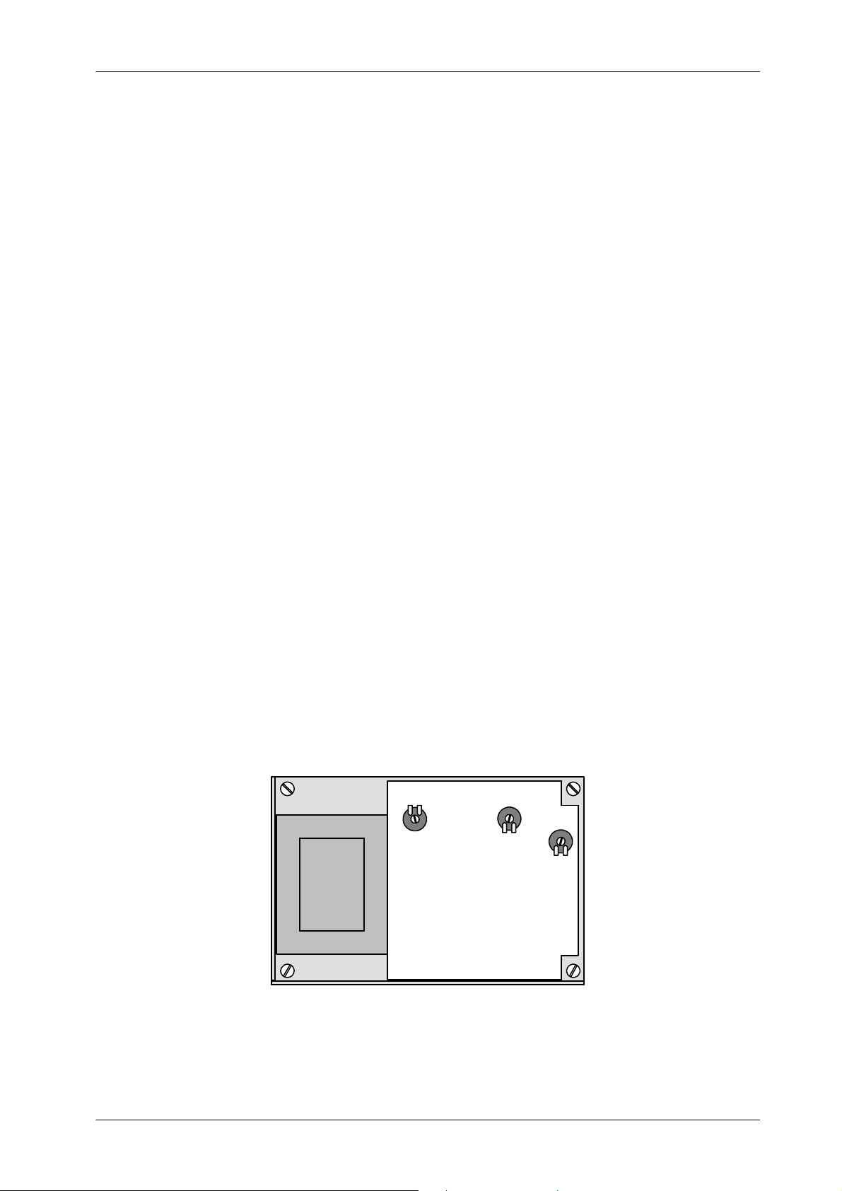
Front Panel (MOD. 3) of the Generator Cabinet. (Refer to Illustration 2-1).
Turn the Generator ON and with a Digital Multimeter measure between:
• P2-3 (+) and P2-4 on the HT Controller Board. Check that the voltage
at this point is +5 ±0.2 VDC. If required, adjust voltage with the +5 VDC
Adjustment Potentiometer on the Power Supply Board.
HF Series Generators
Troubleshooting
• P2-2 (+) and P2-4 on the HT Controller Board. Check that the voltage
• P2-1 (-- ) and P2-4 on the HT Controller Board. Check that the voltage
Illustration 2-1
Power Supply in the Front Panel
at this point is +12 ±0.1 VDC. If required, adjust voltage with the
+12 VDC Adjustment Potentiometer on the Power Supply Board.
at this point is --12 ±0.1 VDC (this voltage must be --12.7 ±0.1 VDC if
the Console is provided with a Graphic Display). If required, adjust
voltage with the --12 VDC Adjustment Potentiometer on the Power
Supply Board.
R26
ADJ. +12 VDC
R25
ADJ. -- 12 VDC
ADJ. +5 VDC
R12
TR-1005R4
POWER SUPPLY BOARD
5
Page 10

HF Series Generators
Troubleshooting
The ATP Console CPU Board operates from a 12 VDC Non-Regulated Supply
located in the Generator Cabinet that supplies to a 5 VDC Switching Regulator
located in the ATP Console CPU Board.
Turn the Generator ON and with a Digital Multimeter measure between:
• TS1-30 (GND) and TS1-29 (+12 V Unr.) on the Generator Cabinet.
Check that the voltage at this point is +12 ±1.5 VDC.
• TP GND and TP +5 on the ATP Console CPU Board. Check that the
voltage at this point is +5 ±0.2 VDC.
Note .
No adjustments are required for both voltage measurements. The
ATP Console CPU Board may be located inside the Console or
inside the Generator Cabinet.
2.2 MICROPROCESSORS AND GENERAL OPERATION
The following LEDs indicate the proper operation of each Microprocessor in the
Generator:
• The LED DS1 located on the HT Controller Board blinks fast during
power up, then slows to a steady blink of about 2 per second, indicating
that the Microprocessor U5 is operating normally.
• The LED DS2 located on the ATP Console CPU Board normally blinks
at the same rate as LED DS1 on the HT Controller Board, indicating that
the Console Microprocessor U30 is operating correctly.
• The LED DS1 located on the Fluoro CPU Board only blinks in Fluoro
mode indicating that the Fluoro Microprocessor is operating correctly.
Also observe the following LEDs to facilitate general troubleshooting:
• When LED DS1 located on the Interface Control Board is ON (lit), it
indicates that the Generator is ON.
• The LED DS1 located on the ATP Console CPU Board is normally ON
(lit), indicating that the Watch-Dog Timer of the Console is operating and
insuring thecorrect timing of data communications with the HT Controller
Board.
6
TR-1005R4
Page 11
HF Series Generators
Troubleshooting
2.3 REPLACEMENT OF MEMORY IN ATP CONSOLE CPU BOARD AND/OR
HT CONTROLLER BOARD
Before starting up the system, you have to set ON the switch A3024SW2--3 at
the ATP Console CPU Board to enable Service Mode. A few seconds after
pressing the ON button on theConsole, you will see E10 (this is shown because
the EPROM U24 has been replaced).
Reset the error indication by pressing the respective button on the Console and
keep it pressed until the Error 10 disappears.
After this, the normal start up will take place.
We recommend setting this switch back to OFF once the installation has been
completed. This will not enable the operator to enter in Configuration or in
Calibration Mode (Service Modes).
2.4 PROCEDURES RELATED TO THE PUSH-BUTTON CONSOLES
2.4.1 APR OPERATION
APR techniques are factory pre-programmed to standard techniques sets. All
parameters of APR techniques may be manually rewritten as required by the
operator and stored in the”APR working file”forlateruse(refer to therespective
Operator Manual).
Note .
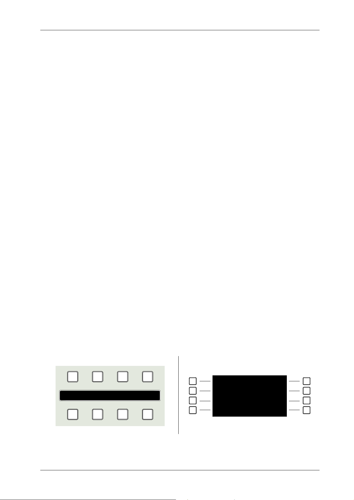
Illustration 2-2
APR Module version in Push-buttons Consoles
1
2 3 4
Display APR
This section only applies to Consoles equipped with Anatomical
Programmer (APR).
2
3
8765
4 8
Display APR
51
6
7
TR-1005R4
7
Page 12
HF Series Generators
Troubleshooting
2.4.2 APR RE-INITIALIZATION
The APR re-initialization makes a new copy of the factory pre-programmed
parameters of theAPR techniquesin the U23-NVRAM of the ATP Console CPU
Board.
APR re-initialization set the APR techniques only for the selected workstation.
To re-initialize the APR techniques, exit the APR mode and press
simultaneously the push-buttons 5-6-7-8 on the APR module. (Refer to
Illustration 2-2).
The APR re- initialization deletes all the APR parameters and
related selections previously modified and stored by the
operator for both X-ray Tubes.
2.4.3 APR BACKUP
2.4.4 APR RESTORE
The APR backup makes a copy of the parameters and selections of the APR
techniques stored in the U23-NVRAM to the U18-E2PROM of the ATP Console
CPU Board. This action make a copy of all the APR techniques stored in the
“APR working file”tothe“APR backup file”.
The APR backup is automatically performed when the equipment is turned
OFF/ON, whenever any APR technique has been modified and stored in the
U23-NVRAM by the operator.
To backup the APR techniques, exit the APR mode and press simultaneously
push-buttons 1-5-6 of the APR module. (Refer to Illustration 2-2).
The APR Restore makes a copy of the parameters and selections of the APR
techniques stored in the U18-E2PROM to the U23-NVRAM of the ATP Console
CPU Board. This action replaces the data stored in the “APR working file”by
thedatastoredinthe“APR backup file” for all the APR techniques.
The APR Restore is automatically performed when the Console is turned
OFF-ON, whenever any problem had been detected during the U23-NVRAM
checksum.
To restore the APR techniques, turn the Console ON and with the APR mode
OFF press simultaneously the push-buttons 4-7-8 of the APR module. (Refer
to Illustration 2-2).
8
TR-1005R4
Page 13
HF Series Generators
T
heC
dtheG
TheConsolebeepsbeforestar
t
p
perf
p
p
Upperfansarestopped
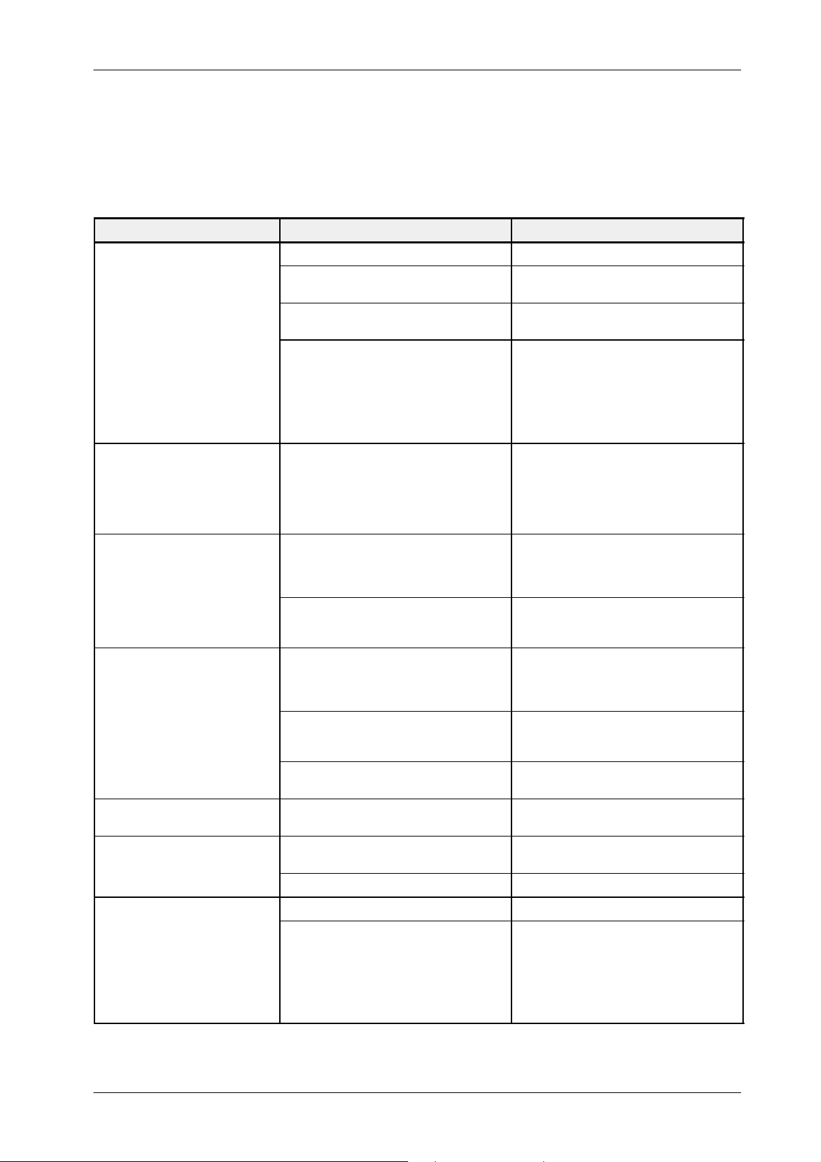
2.5 PROCEDURES RELATED TO THE TOUCH SCREEN CONSOLES
DESCRIPTION POSSIBLE CAUSES ACTIONS
Malfunction of the Power-ON button. Check if the button works properly.
Troubleshooting
onsolean
do not start up.
The Console starts but the
Generator do not start.
The Console beepsbefore start.
enerator
Cable connection or cable status.
Generator / Console is not connected to
mains.
Power Supply does not work properly.
Cable A7067--xx is not properly connected
BIOS error. If there is a problem with the
video chipset the beep code will consist of a
single long beep followed by three short
beeps
.
BIOS error. If there is a problem with the
DRAM, the beep code will consist of a single
long beep repeatedly.
The TFT inverter is not working properly.
Check that all the internal cable are
connected. (A7031--xx Cable)
Power ON the Generator / Console.
Check all the power connectors from/to the
power supply (power values are +5V and
+12V).
Check the power input selector, change the
power supply (Kit Power Supply) if the
selector is wrong.
Connect again this cable.
Check all the cables to the board. If the
problem persist, change the A3515--02
board (you should also check the
connection to the Generator)
Disconnect the power connector. Wait ten
seconds and connect it again. Push the
power button and if the problem persists,
replace the mainboard.
Check that the DRAM is connected right. If
so, try to reboot the system, and if the
problem persists, replace the mainboard.
First check that the fans are working. If so,
check that cable 55001042 is right
connected. Replace the inverter if the
problem persists.
There is no image on the screen.
The operator application is not
launched
U
ans are sto
Touch panel. If you push a button,
and nothing happens, or another
button is selected
ed
TR-1005R4
Try to move the cable. If the screen
Cable 55001042 is broken.
Mainboard is broken.
The operating system is not working
properly.
Power cable is broken
Fan broken Change the kit fans Console
Calibration error of the touch panel controller Check the calibration process.
Touch panel controller is broken.
suddenly bright, replace Kit TFT Screen
TPC 12”.
Replace the mainboard. If the problem
persists, replace the whole Console.
Replace the Compact Flash Card.
Check the power cable. If it is broken,
replace the power supply
Check that there is a blinking led in the
controller. If not, check the power supply.
If it is correct, replace the Controller.
When the panel is pushed, the led is on
continuously. If not, replace the kit TFT
Screen TPC 12”. If the problem persists,
replace the Kit PC GESPAC.
9
Page 14

HF Series Generators
Troubleshooting
2.5.1 SOFTWARE UPGRADE
If the Touch Screen Application is provided with a “Software Upgrade” button
on the Service Mode Menu, it is used to close the Application Program without
turning OFF the System. After pressing this button, the Console shows the PC
Desktop to enable the Application Software Upgrade, Language Configuration
of the PC Operating System or Touch Screen Sensor Calibration.
Note .
To perform any of these operations, it is necessary to connect a
Keyboard to the connector labelled “Kb” on the back side of the
Touch Screen Console.
Please, make sure that the Keyboard connector is suitable
(MiniDin type).
2.5.2 TOUCH SCREEN SENSOR CALIBRA TION
If required to calibrate the Sensor of the Touch Screen because the buttons can
not be properly selected or because the Compact Flash has been changed,
perform the next procedure:
1. Enter in “Service Mode” and press the “Software Upgrade” button.
2. On the PC Desktop, press the“Start--Windows” button on the keyboard
connected to the Touch Screen Console, then select: “Programs / UPDD
/ Calibrate”.
10
3. Execute the “Calibrate” program and follow the process clicking on the
indicated places.
4. When finish this calibration, come back to the Application by entering
again in “Start” and select: “Programs / Start up (select the first one) /
Console”.
TR-1005R4
Page 15

2.5.3 EXTERNAL BACKUP OF THE APR TECHNIQUES
1. Connect a Laptop (PC) to the Touch Screen Console with a serial cable
(DB9 with female pins on both ends; on one end Pin 2 connected with
Pin 3; on the other end Pin 2 connected with Pin3; Pin 5 connected with
Pin 5). Connect the serial cable to port “COM4” of the Touch Screen
Console and any free port on the Laptop (PC).
2. On the Laptop (PC):
a. Select: “StartMenu / Programs / Accessories / Communications
/ Hyperterminal / hypertrm.exe”.
b. Once the Hyperterminal is opened on the Laptop (PC), configure
the connection. For that select on the Menu bar:
HF Series Generators
Troubleshooting
File --> Properties --> Connect using: COM *
(selected free port)
Configure --> Bits per second: 115200
Data Bits: 8
Parity: None
StopBits: 1
Flow Control: None
c. Then press “OK” and “OK”.
d. Select on the Menu bar: Transfer --> Receive File
on this window select:
Place received file in the following folder:
(choose a folder in the Laptop)
Use receiving protocol:
Xmodem
e. Let that window open without pressing “Receive”, by the moment.
TR-1005R4
3. On the Touch Screen Console:
a. Enter in “Service Mode” and press the “Software Upgrade” button.
b. Press the “Start--Windows” button on the keyboard connected to
the Touch Screen Console, then select: “Programs / accessories
/ hyperterminal / PORT4.ht”.
11
Page 16

HF Series Generators
Troubleshooting
c. Once the Hyperterminal is opened on the Touch Screen Console,
configure the connection. For that select on the Menu bar:
File --> Properties --> Connect using: COM4
Configure --> Bits per second: 115200
Data Bits: 8
Parity: None
StopBits: 1
Flow Control: None
d. Then press “OK” and “OK”.
e. Select on the Menu bar: Transfer --> Send File
on this window select:
Filename:
C:\ program files\Rad_Console (this name can be different)
\APR_English.ini (or APR_French.ini, or APR_Spanish.ini,
or APR_German.ini, or APR_Italian.ini, or
APR_Portuguese.ini, according to the APR language
previously selected on the Settings / Settings Menu.)
Use sending protocol:
Xmodem
f. Let that window open without pressing “Send”, by the moment.
4. Press “Reveice” on the Laptop (PC) window. It will ask for the name to
save the file: Type “APR_English.ini” (or APR_French.ini, or
APR_Spanish.ini, or APR_German.ini, or APR_Italian.ini, or
APR_Portuguese.ini, according to the APR language previously
selected on the Settings / Settings Menu.)
5. Press “Send” on the Touch Screen window.
6. Wait until the transference is complete (this can take a few minutes)
12
7. When the transference is complete, close the Hyperterminal application
in the Laptop and Touch Screen Console. Disconnect the serial cable.
8. On the Touch Screen, press the“Start--Windows” button on the keyboard
and select: “Programs / Start up (select the first one) / Console”, to come
back to the Application.
TR-1005R4
Page 17
HF Series Generators
Troubleshooting
2.6 PROCEDURES RELATED TO THE BATTERY POWERED GENERATORS
CAREFULLY HANDLE ALL INTERNAL PARTS OF THE
EQUIPMENT, SPECIFICALLY PARTS UNDER COVERS.
DANGEROUS DC VOLTAGE IS PRESENT IN THE UNIT EVEN
IF IT IS UNPLUGGED FROM THE AC LINE.
THE HEAT SINKS ON THE BATTERY CHARGER BOARD ARE
NOT ELECTRICALL Y ISOLATED. DANGEROUS VOLTAGE IS
PRESENT. DO NOT TOUCH OR SHORT THESE HEAT SINKS
TO ONE ANOTHER NOR TO ANY OTHER CIRCUIT
COMPONENTS.
KEEP IN MIND THE GENERAL CAUTIONS FOR BATTERY
POWERED GENERATORS INDICATED IN SECTION 1.2.
Note .
2.6.1 BATTERY CHARGER TEST
Before performing the following procedure, be sure that the unit
has been connected to mains enough time (recommended eight
hours) for a full charging of all the Batteries.
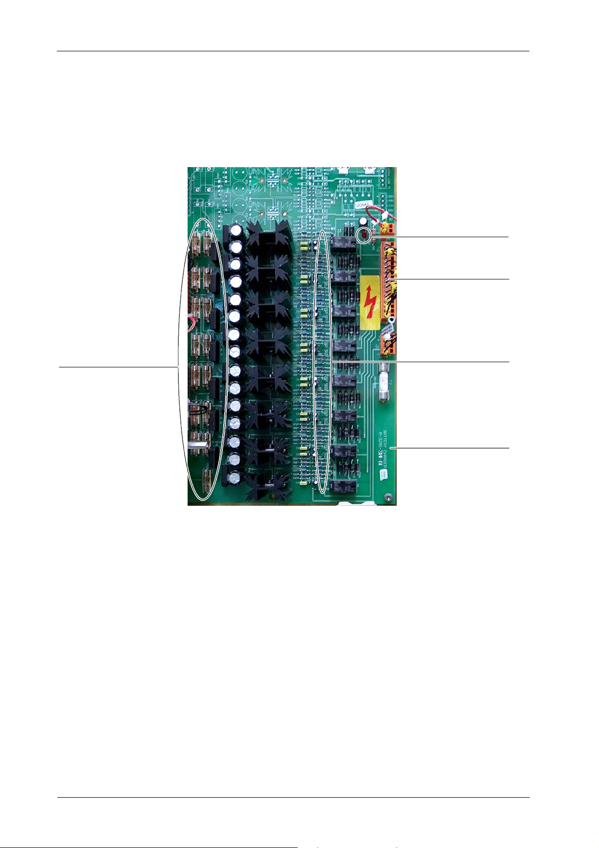
The Battery Charger Board consists of several Battery Chargers or Sectors.
Each Sector charges two 12 volt Batteries and has one green LED which is
used to provide a visual indication of the Charger and Battery status.
All green LEDs and the LED DS1 on the Battery Charger Board should be
lighting when the line power is being supplied. It indicates that the chargers
(sectors) are operating correctly. Also the external Power Line Indicator Lamp
(green Neon) is On (charging). (Refer to Illustration 2-3).
TR-1005R4
13
Page 18
HF Series Generators
Troubleshooting
Illustration 2-3
Battery Charger Board
LED DS1
Connector J1
Fuses of Battery Sectors
Row of Green LEDs
Charger Board
If all of the green LEDs are not lighting and the “Line Present” external Lamp
is off, check that the Input Line Magnetothermic 1SW1 is in ON position. If it is
in ON position and all of the green LEDs are not lighting, check that Yellow LED
DL1 on the Line Monitor Board is blinking. if LED DL1 is not blinking check:
• If the Line Monitor Board is working properly (refer to Error Code E25 in
this document) and replace it if necessary.
14
• If one of the Red LEDs DL2 or DL3 on the Line Monitor Board is lighting.
It means that the Input Line is too high (DL3) or too Low (DL2).
If the Line Monitor Board is working properly, then check primary and secondary
connections on Transformer 2T1. If some green LEDs are lighting and some
are not, check secondary connections on Transformer 2T1 and/or circuit
operation and fuse of each individual charger that are not lighting.
TR-1005R4
Page 19
HF Series Generators
Troubleshooting
If error “E25” is shown on the Console and exposures are inhibited, perform the
following procedures:
1. If the green LED of any sector is off, check the respective components
and power supply of that sector. If they are defective, replace the Battery
Charger Board.
2. Check that voltage supplied from the Battery Charger Board for charging
every couple of Batteries (one sector) is the correct voltage.
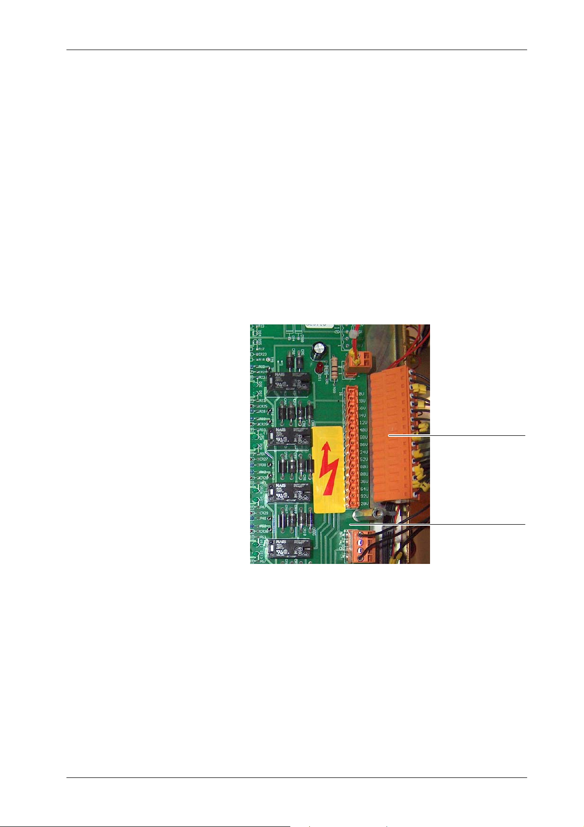
a. Turn OFF the Unit with the Input Line Magnetothermic 1SW1 in
OFF position.
b. Remove Connector J1 from the Battery Charger Board.
Connector J1
Charger Board
c. Turn ON the Unit with the Input Line Magnetothermic 1SW1 in ON
position.
d. At this moment check on the Battery Charger Board that all the
green LEDs and the LED DS1 are lighting. If not, replace the
Battery Charger Board.
TR-1005R4
15
Page 20
HF Series Generators
Troubleshooting
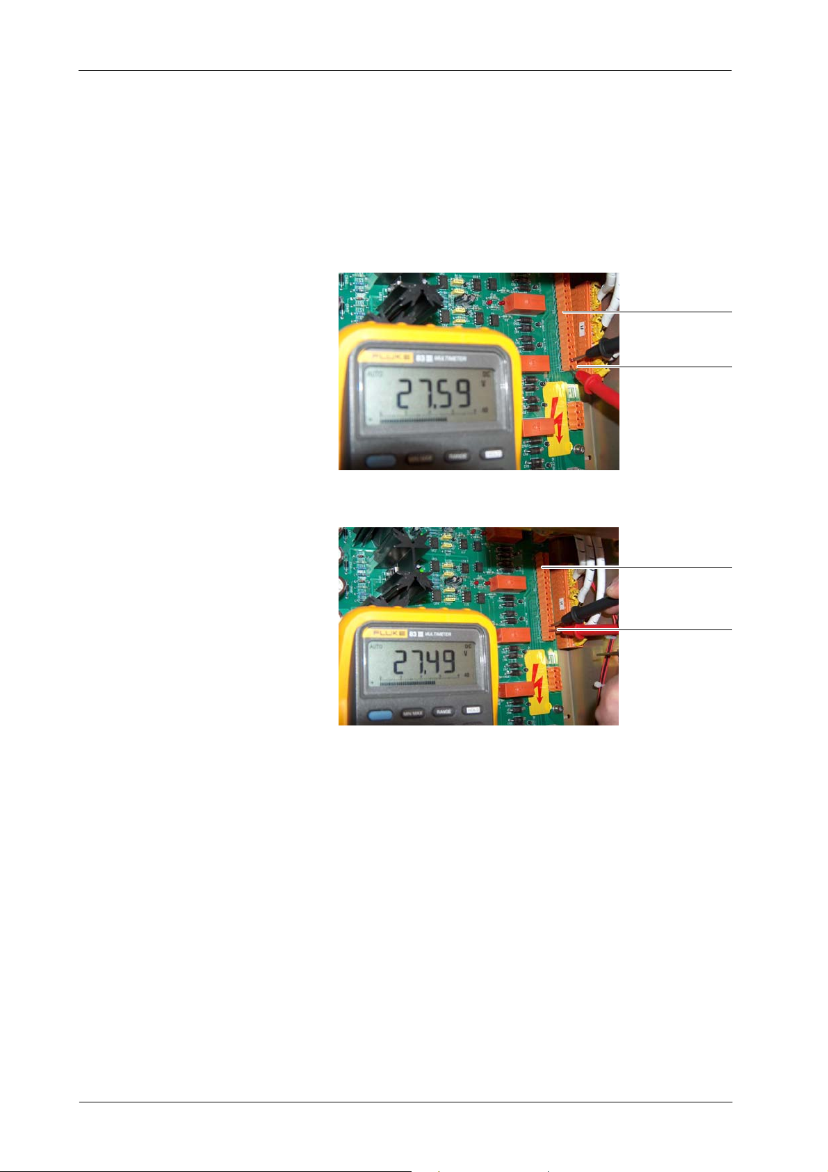
e. If the LED lights are correct, measure between all consecutive
pins of Connector J1 (base). Voltage between consecutive pins
should be around 27.5 V. If this measure is wrong it means that
the last charging sector in board is defective and the Battery
Charger Board must be replaced.
Base of Connector J1
Consecutive Pins
Measurement
Measurement at Pins 1--2
Base of Connector J1
Consecutive Pins
Measurement
Measurement at Pins 2--3
f. After checking it, turn OFF the Unit with the Input Line
Magnetothermic 1SW1 in OFF position. Replace the Battery
Charger Board if it is necessary and connect J1 and the rest of
connectors.
g. Turn ON the Unit with the Input Line Magnetothermic 1SW1 in ON
position.
16
3. Check always the Batteries status as described in Section 2.6.2 -Identifying and Replacing Defective Batteries.
TR-1005R4
Page 21
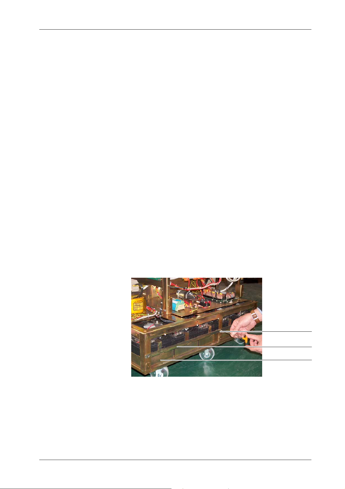
2.6.2 IDENTIFYING AND REPLACING DEFECTIVE BA TTERIES
Batteries have a life time after which they should be replaced as they go bad.
The problem arises at the moment of determining if the Battery is good or
defective and need to replace it.
Tools required to determine which Batteries are defective:
• Allen Screwdriver Set (Standard service tool).
• Digital Multimeter.
• Load Resistance of 3 Ohms, > 50 Watts.
HF Series Generators
Troubleshooting
Note .
Before performing the following procedure, be sure that the unit
has been connected to mains enough time (recommended eight
hours) for a full charging of all the Batteries.
1. Turn OFF the Unit with the Input Line Magnetothermic 1SW1 in OFF
position.
2. Remove the Protection Plate of the Battery Trays (3 Allen screws).
Allen Screws
Protection Plate
Battery Tray
TR-1005R4
17
Page 22
HF Series Generators
Troubleshooting
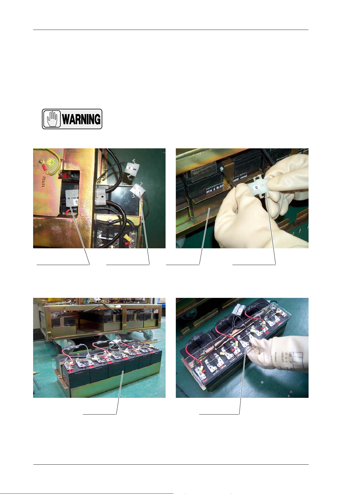
3. Take out the first Battery Tray disconnecting before the Anderson and
Molex Connectors of the Battery Tray. Remove the Protection Cover of
the Battery Tray.
USE PROTECTION GLOVES AGAINST ELECTRIC SHOCK
HAZARDS AND SAFETY GLASSES WHEN HANDLING
BA TTERIES DURING SERVICE TASKS.
Anderson Connectors
Molex Connector
Battery Tray Protection Cover
Battery Tray
Molex Connector
18
TR-1005R4
Page 23
Negative pole (black)
Battery to be Measured
HF Series Generators
Troubleshooting
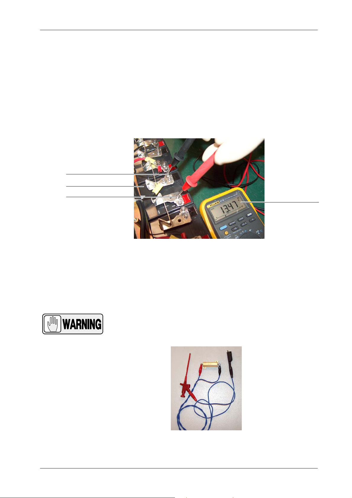
4. Identify the positive and negative poles of the Battery to be measured.
Measuring the output voltage of the Battery is not enough to determine
whether a Battery is OK. The image bellow shows the measurement of
a Battery which has good voltage (around 12V) as shown in the
Multimeter.
This measurement can lead us to the thought that the Battery is in good
condition, but this is a voltage without load.
Positive Pole (red)
without Load Resistance
Volts measured
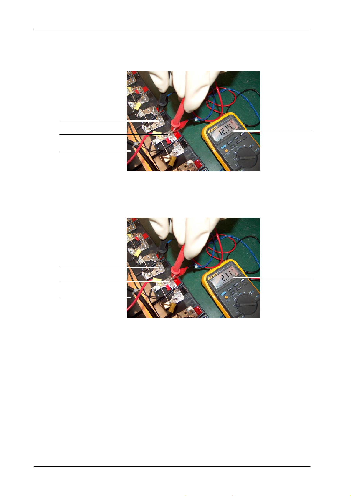
5. Connect the Load Resistance (3 Ohms, > 50 Watts) to the positive and
negative Battery poles. Repeat the voltage measurement with the Load
Resistance connected. If the voltage with load is less than 10 V (usually
close to 0 V), the Battery is not good since it will never be completely
loaded.
BE CAREFUL WITH THE LOAD RESISTANCE AS IT MAY GET
VERY HOT DURING THE TEST.
TR-1005R4
Load Resistance
19
Page 24
HF Series Generators
Troubleshooting
Negative pole (black)
Positive Pole (red)
Battery to be Measured
Negative pole (black)
Positive Pole (red)
Volts measured
with Load Resistance
Battery in good condition
Volts measured
with Load Resistance
Battery to be Measured
Battery in bad condition
20
TR-1005R4
Page 25
HF Series Generators
Troubleshooting
6. Follow the Battery testing with the rest of Batteries and after checking all
of them replace the defective Batteries as described in the next step.
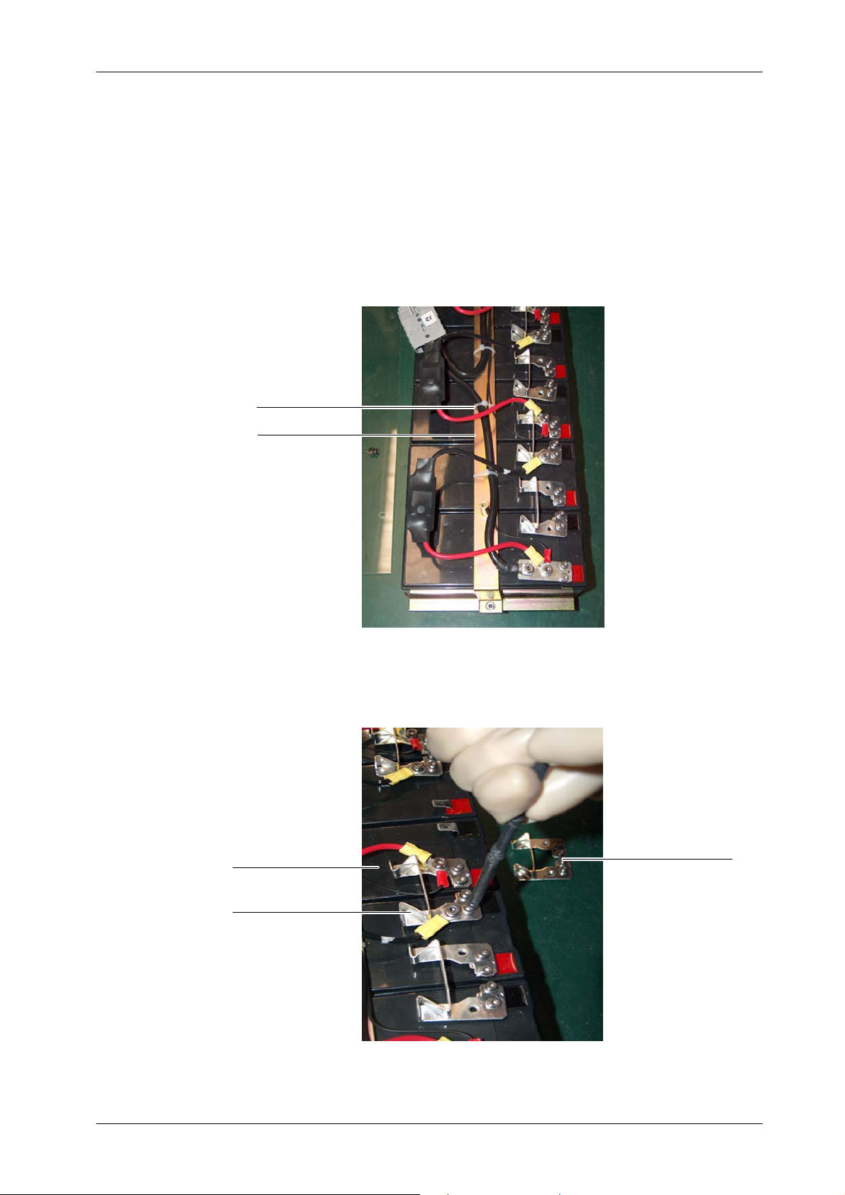
7. Battery replacement:
a. Cut the ty-straps needed to replace the Battery and remove the
Metallic Bar on the Battery Tray.
Ty--Straps
Metallic Bar
b. CAREFULLY, disconnect the contact terminals of the Battery
Battery to be replaced
Contact T erminals
(negative and positive poles) using an isolated Allen Screwdriver.
Contact T erminals
TR-1005R4
21
Page 26
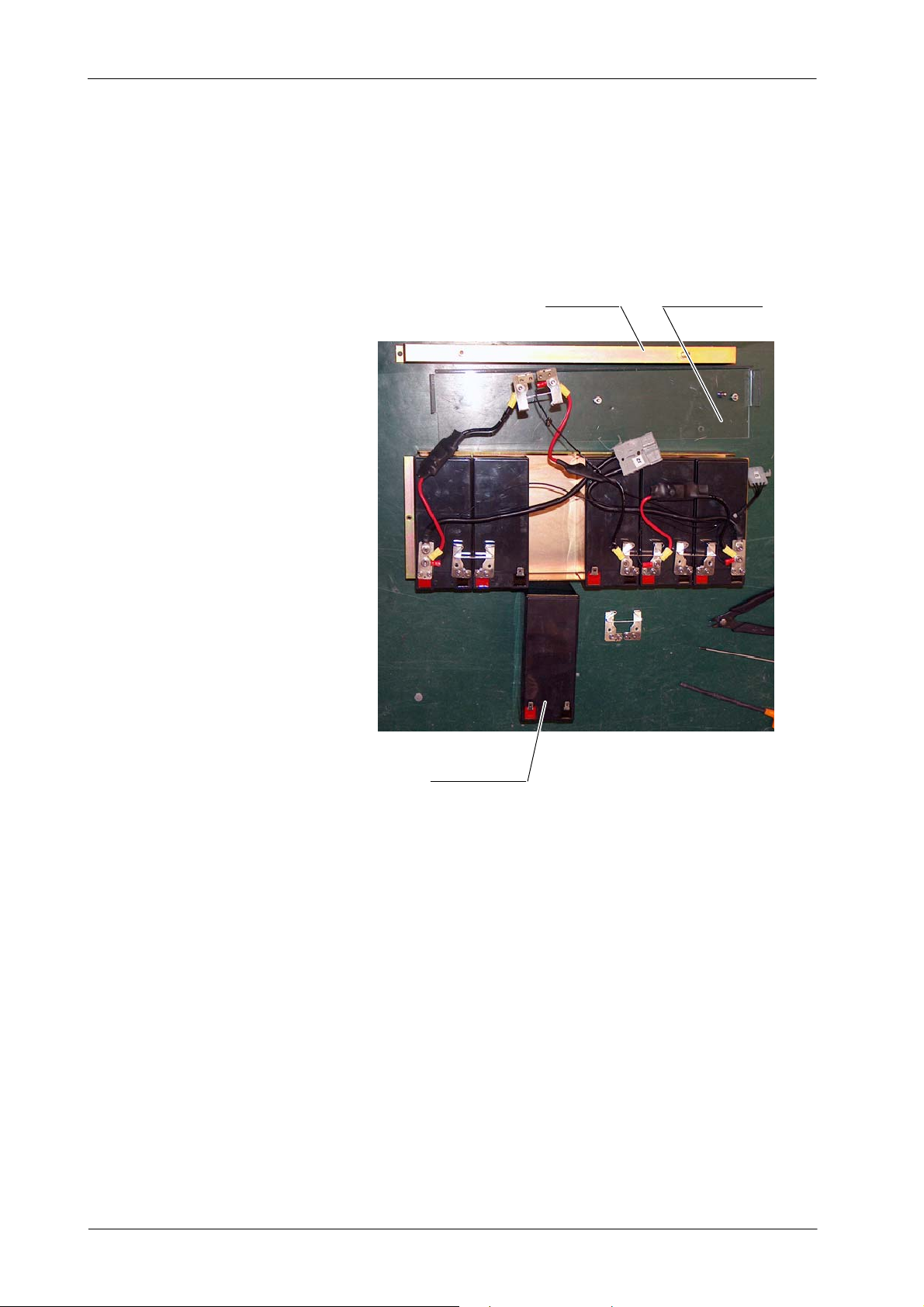
HF Series Generators
Troubleshooting
c. CAREFULLY, place the new Battery, connect the terminals of the
Battery again, and re-install the ty-straps, Metallic Bar and
Protection Cover over the Batteries.
Metallic Bar Protection Cover
New Battery
d. CAREFULLY, re-install the Battery Tray inside the Cabinet
connecting the respective Anderson and Mollex Connectors.
Screw the lateral Protection Plate of the Battery Trays.
22
TR-1005R4
Page 27
HF Series Generators
Troubleshooting
2.7 PROCEDURES RELATED TO THE CAPACITOR ASSISTED GENERATORS
CAREFULLY HANDLE ALL INTERNAL PARTS OF THE
EQUIPMENT, SPECIALLY PARTS UNDER COVERS.
DANGEROUS DC VOLTAGE IS PRESENT IN THE UNIT EVEN
IF IT IS UNPLUGGED FROM THE AC LINE.
NEVER TOUCH META L PARTS UNDER COVERS BEFORE
TESTING THAT VOLTAGE IS BELOW 10 VDC. PERFORMTHE
PROCEDURE FOR CAPACITORS DISCHARGING AND
VOLTAGE TESTING PREVIOUS TO MANIPULATE INSIDE
THE GENERATOR FOR SERVICE.
KEEP IN MIND THE GENERAL CAUTIONS FOR CAPACITOR
ASSISTED GENERATORS INDICATED IN SECTION 1.2.
2.7.1 PROCEDURE FOR STORAGE CAPACITORS DISCHARGING AND VOLTAGE TESTING
1. With the Generator turned OFF, be sure that the Power Supply Cable is
unplugged from the Mains socket.
2. Take away the Generator cover.
3. Carefully, remove the Protection Cover over the Capacitor Charger
Board (A3517--xx). DO NOT TOUCH ANY METAL PART UNDER
COVERS UNTIL THE CAPACITORS ARE FULLY DISCHARGED
AFTER THIS PROCEDURE.
4. Resistor 8R1 (1K5 ohms, 250 W) is assembles close to the Capacitor
Charger Board to allow the Capacitors discharging. Connector J4 (from
this resistor) must be disconnected for normal operation of the Unit, and
ONLY MUST BE CONNECTED to the J4 of the Capactitor Charger
Board for Capacitors discharging process.
5. Plug Connector J4 in the Capacitor Charging Board. Check that LEDs
D48 and D49 of this Board are blinking. When the Capacitors are fully
discharged, both LEDs will be OFF. Capacitors will be discharged from
800 VDC (fully charged) to 10 VDC in approximately 5 minutes.
TR-1005R4
+(060612)
23
Page 28
HF Series Generators
Troubleshooting
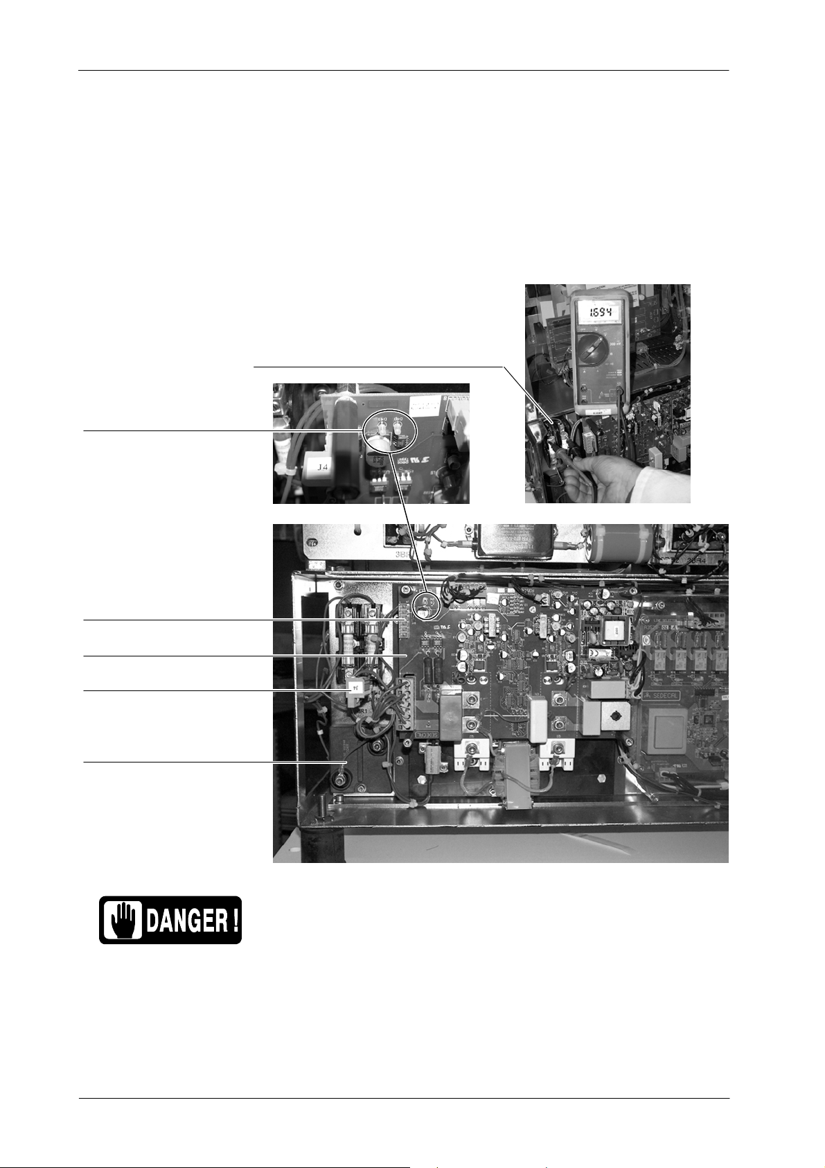
6. Check that the voltage stored in Capacitors is < 10 VDC (maximum
voltage for a safe service manipulation). It is recommended that voltage
will be close to 0 VDC. For that, check that LEDs D48 and D49 are OFF,
and then measure the voltage at the base of Fuses 8F3 and 8F4.
Illustration 2-4
Connection of J4 for Capacitor Discharging
Check that voltage on 8F3 and 8F4 is < 10 VDC
LEDs D48 & D49
Connector J4 (PCB Connector)
Capacitors Charging Board
Connector J4 (Aerial Connector)
Resistor 8R1
Note .
DO NOT MANIPULA TE INSIDE THE UNIT WITHOUT
CHECKING THAT VOLTAGE IN CAPACITORS MODULE HAS
BEEN DISCHARGED (LESS THAN 10 VDC).
Storage Capacitors are fully charged four seconds after turning
the Generator ON (for a line of 230 VAC with selection of 20 A in
the Generator, or maximum 40 seconds for a line of 110 VAC with
selection of 8 A in the Generator).
24
+(060612)
TR-1005R4
Page 29
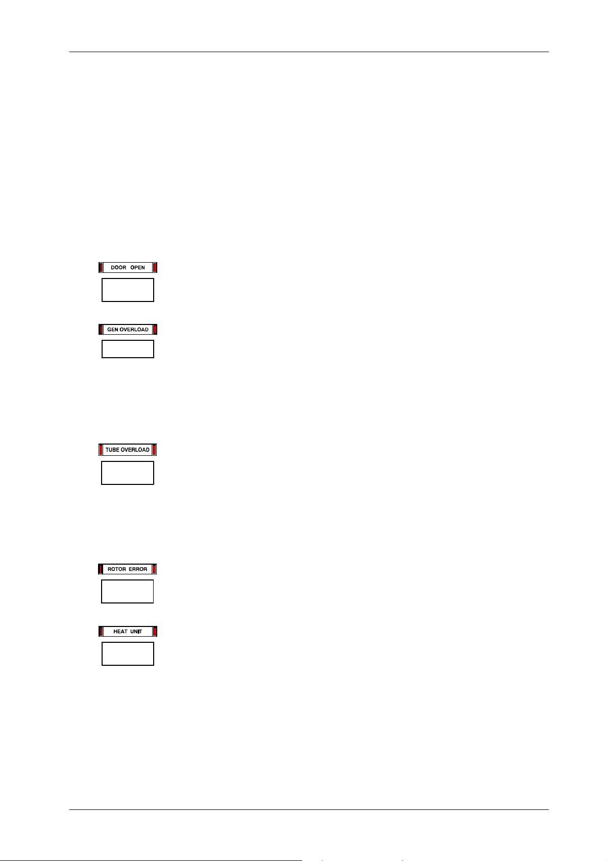
SECTION 3 SELF- DIAGNOSIS INDICATORS
Some Console are provided with Self-Diagnosis indicators that identify a
malfunction in the system alerting operator about error existence that inhibits
exposure. During normal operation of the system, these indicators are directly
shown on the Console (depending on the Console model they can be shown
on the APR Display, Console Indicators, Warning Messages Area, etc).
DOOR OPEN: Indicatesthe X-rayroom door is open when the X-ray equipment
DOOR
G.OVL
is in use. (Also refer to Error Code “E35”).
GENERATOR OVERLOAD: Indicates that the exposure has been interrupted
because during exposure has been produced arcing or bad function on the HV
circuitry (X-ray Tube, HV Transformer and/or HV Cables) or a failure of IGBT
module (overheated or defective IGBTs) has been detected. (Also refer to Error
Code “E09”).
HF Series Generators
Troubleshooting
T.OVL
ROTOR
HEAT
It can be also shown making a high power and long exposure with the X-ray tube
cool (X-ray Tube has not been warmed-up).
TUBE OVERLOAD: Indicates that either the technique selected is beyond the
X-ray tube ratings or the present conditions of the X-ray tube inhibit the
exposure (anode overheated). Parameters for next exposure may be
temporally limited by the Generator (change the exposure values or wait for the
X-ray tube to cool). (Also refer to Error Code “E37”).
Check that heat units available are lower than the calculated for the next
exposure. Reduce exposure factors or wait for the X-ray tube to cool.
ROTOR ERROR: Indicates that the X-ray tube anode is not rotating while
“Prep” is active, then exposures are inhibited. (Also refer to Error Code “E18”).
HEAT: Indicates that the X-ray Tube thermostat / pressurestat is open due to
overheating of the tube housing (housing is too hot, wait for the housing to cool)
or to a thermostat / pressurestat mal-function (housing is cool). Heat units may
raise to any value. (Also refer to Error Code “E36”).
TR-1005R4
25
Page 30
HF Series Generators
Troubleshooting
TECH
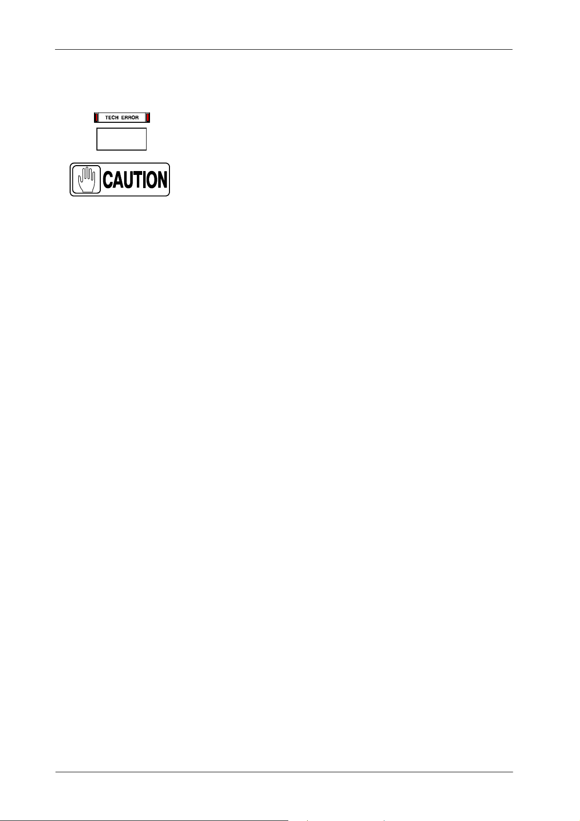
TECHNIQUE ERROR: If it activates during exposure it means that:
The exposure has been interrupted by the “Security Timer”
because of a system failure. Call Field Service. (Also refer
to Error Code “E34”).
This error can also be shown:
• after an APR technique selection to advise that exposure parameters
displayed on the Console are not the values stored for this APR
technique. Exposure parameters are adapted by the Generator to
another enable values. (Also refer to Error Code “E34”).
• after the “ABC” selection, when ABC is not enable. (Also refer t o Error
Code “E34”).
• if a failure on the Automatic Collimator has been detected (blades are full
open or in movement during exposure, etc.). In this case the indicator
light is constant (not blinking). (Also refer to Error Code “E48”).
26
TR-1005R4
Page 31
SECTION 4 ERROR CODES
ERROR CODE LIST
ERROR CODE DESCRIPTION
“------------” SYSTEM FAILURE. FATAL ERROR.
HF Series Generators
Troubleshooting
E01
E02
E03 FAILURE IN POWER UP ROUTINE. ALL WORKSTATIONS ARE UNCONFIGURED.
E04 “PREP” SIGNAL RECEIVED WITHOUT CONSOLE ORDER.
E05 “FLUORO” SIGNAL ACTIVE WITHOUT REQUEST.
E06 “PREP” OR/AND “EXPOSURE” ORDERS ACTIVATED DURING POWER UP ROUTINE.
E07 WRONG DATA FOR X-RAY TUBE-2.
E08 WRONG DATA FOR X-RAY TUBE-1.
E09 GENERATOR OVERLOAD. ARCING OR IGBT FAULT.
E10
E11 NO VOLTAGE IN CAPACITOR BANK.
E12 NO mA DURING EXPOSURE OR mA OUT OF TOLERANCE. WRONG FILAMENT CURRENT.
E13 NO kVp DURING EXPOSURE OR kVp OUT OF TOLERANCE.
E14 EXPOSURE SIGNAL WITHOUT X-RAY EXPOSURE CONSOLE COMMAND.
E15 NO CURRENT ON FILAMENT. WRONG SELECTION OF FOCAL SPOT DETECTED DURING “PREP”.
E16 INVALID VALUE OF: kVp, mA OR kW.
FAILURE IN POWER UP ROUTINE.
NO COMMUNICATION LINK BETWEEN HT CONTROLLER BOARD AND ATP CONSOLE CPU BOARD.
FAILURE IN POWER UP ROUTINE. RAD GENERATOR CONFIGURED AS R&F GENERATOR.
NO COMMUNICATION LINK BETWEEN ATP CONSOLE CPU BOARD AND FLUORO CPU BOARD.
EEPROM CORRUPTED OR NO INITIALIZED ON ATP CONSOLE CPU BOARD OR ON HT CONTROLLER
BOARD. WRONG DATA CALIBRATION.
E17 COMMUNICATION ERROR BETWEEN ATP CONSOLE CPU BOARD AND HT CONTROLLER BOARD.
E18 ROTOR RUNNING WITHOUT ORDER OR ROTOR ERROR.
E19 mA DETECTED WITHOUT “EXPOSURE” ORDER.
E20 kVp DETECTED WITHOUT “EXPOSURE” ORDER.
E21 WRONG TUBE-1 SELECTION.
E22 WRONG TUBE-2 SELECTION.
E23 CALIBRATION DATA NOT STORED.
E24 THE BUCKY HAS NOT BEEN DETECTED TO BE MOVING.
E25 BATTERY FAILURE IN BATTERY POWERED GENERATORS.
E26 VOLTAGE FAILURE IN BATTERY POWERED GENERATORS WITH STAND-ALONE.
E27 FAILURE IN CONSOLE EPROM. BAD CHECKSUM.
TR-1005R4
27
Page 32
HF Series Generators
Troubleshooting
ERROR CODE LIST
ERROR CODE DESCRIPTION
E29 ALL CLEAR SIGNAL NOT ACTIVE -- NUCLETRON GENERATOR.
E30 RELAY K1 NOT ACTIVE -- NUCLETRON GENERATOR.
E31 LONG EXPOSITION IS NOT INITIATED -- NUCLETRON GENERATOR.
E32 LONG EXPOSITION IS NOT CUT AFTER 3.2 SECONDS -- NUCLETRON GENERATOR.
E33 NO COMMUNICATION LINK BETWEEN GENERATOR AND SERIAL CONSOLE OR PC UNIT.
E34 TECHNIQUE ERROR.
E35 DOOR OPEN.
E36 HEAT UNITS. OVERHEATING.
E37 TUBE OVERLOAD.
E41 DOSIMETER -- COMMUNICATION FAILURE BETWEEN TUBE-1 DOSIMETER AND GENERATOR.
E42 DOSIMETER -- AUTOTEST ERROR ON TUBE-1 DOSIMETER.
E43 DOSIMETER -- TUBE-1 ION CHAMBER STATUS CHECK ERROR.
E44 DOSIMETER -- COMMUNICATION FAILURE BETWEEN TUBE-2 DOSIMETER AND GENERATOR.
E45 DOSIMETER -- AUTOTEST ERROR ON TUBE-2 DOSIMETER.
E46 DOSIMETER -- TUBE-2 ION CHAMBER STATUS CHECK ERROR.
E47 CAPACITOR ASSITED GENERATOR -- CAPACITOR NOT CHARGED WHEN “PREP”.
E48 COLLIMATOR ERROR.
E49 EXPOSURE CYCLE ERROR.
E50 INTERRUPTED EXPOSURE.
E51 DRAC -- CHECKSUM FAILURE OR EPROM CORRUPTED.
E52 DRAC -- MICROCONTROLLER RAM FAILURE.
E53 DRAC -- INSUFFICIENT DC BUS VOLTAGE AT LOW LEVEL VOLTAGE (220 VAC).
E54 DRAC -- INSUFFICIENT DC BUS VOLTAGE AT HIGH LEVEL VOLTAGE (480 VAC).
E55 DRAC -- EXCESSIVE DC BUS VOLTAGE AT HIGH LEVEL VOLTAGE (480 VAC OR 380 VAC).
E56 DRAC -- EXCESSIVE REFERENCE VOLTAGE.
E58 DRAC -- EXCESSIVE CURRENT IN MAIN WINDING DURING ACCELERATION UP TO 3300 RPM.
E59 DRAC -- EXCESSIVE CURRENT IN AUXILIAR WINDING DURING ACCELERATION UP TO 3300 RPM.
E60 DRAC -- INSUFFICIENT CURRENT IN AUXILIAR WINDING DURING ACCELERATION UP TO 3300 RPM.
E61 DRAC -- INSUFFICIENT CURRENT IN MAIN WINDING DURING ACCELERATION UP TO 3300 RPM.
E62 DRAC -- EXCESSIVE CURRENT IN MAIN WINDING DURING ACCELERATION UP TO 10000 RPM.
E63 DRAC -- EXCESSIVE CURRENT IN AUXILIAR WINDING DURING ACCELERATION UP TO 10000 RPM.
E64 DRAC -- INSUFFICIENT CURRENT IN AUXILIAR WINDING DURING ACCELERATION UP TO 10000 RPM.
E65 DRAC -- INSUFFICIENT CURRENT IN MAIN WINDING DURING ACCELERATION UP TO 10000 RPM.
28
TR-1005R4
Page 33
ERROR CODE LIST
ERROR CODE DESCRIPTION
E66 DRAC -- EXCESSIVE CURRENT IN MAIN WINDING RUNNING AT 3300 RPM.
E67 DRAC -- EXCESSIVE CURRENT IN AUXILIAR WINDING RUNNING AT 3300 RPM.
E68 DRAC -- INSUFFICIENT CURRENT IN AUXILIAR WINDING RUNNING AT 3300 RPM.
E69 DRAC -- INSUFFICIENT CURRENT IN MAIN WINDING RUNNING AT 3300 RPM.
E70 DRAC -- EXCESSIVE CURRENT IN MAIN WINDING RUNNING AT 10000 RPM.
E71 DRAC -- EXCESSIVE CURRENT IN AUXILIAR WINDING RUNNING AT 10000 RPM.
E72 DRAC -- INSUFFICIENT CURRENT IN AUXILIAR WINDING RUNNING AT 10000 RPM.
E73 DRAC -- INSUFFICIENT CURRENT IN MAIN WINDING RUNNING AT 10000 RPM.
E74 DRAC -- EXCESSIVE CURRENT IN MAIN WINDING BRAKING AT 3300 RPM.
E75 DRAC -- EXCESSIVE CURRENT IN AUXILIAR WINDING BRAKING AT 3300 RPM.
HF Series Generators
Troubleshooting
E76 DRAC -- INSUFFICIENT CURRENT IN AUXILIAR WINDING BRAKING AT 3300 RPM.
E77 DRAC -- INSUFFICIENT CURRENT IN MAIN WINDING BRAKING AT 3300 RPM.
E78 DRAC -- EXCESSIVE CURRENT IN MAIN WINDING BRAKING AT 10000 RPM.
E79 DRAC -- EXCESSIVE CURRENT IN AUXILIAR WINDING BRAKING AT 10000 RPM.
E80 DRAC -- INSUFFICIENT CURRENT IN AUXILIAR WINDING BRAKING AT 10000 RPM.
E81 DRAC -- INSUFFICIENT CURRENT IN MAIN WINDING BRAKING AT 10000 RPM.
E82 DRAC -- WRONG X-RAY TUBE SELECTION.
E83 DRAC -- EXCESSIVE CURRENT IN DC BRAKE.
E84 DRAC -- INCORRECT TUBE SELECTION SIGNAL.
E85 DRAC -- INCORRECT TUBE SELECTION SIGNAL.
E86 DRAC -- INCORRECT TUBE SELECTION SIGNAL.
E87 DRAC -- INSUFFICIENT CURRENT IN COMMON WIRE DURING ACCELERATION UP TO 3300 RPM
E88 DRAC -- INSUFFICIENT CURRENT IN COMMON WIRE RUNNING AT 3300 RPM
E89 DRAC -- INSUFFICIENT CURRENT IN COMMON WIRE DURING ACCELERATION UP TO 10000 RPM
E90 DRAC -- INSUFFICIENT CURRENT IN COMMON WIRE RUNNING AT 10000 RPM
E91 DRAC -- INCORRECT MEASURE AT IPRINC (CH2)
E92 DRAC -- INCORRECT MEASURE AT IAUX (CH3)
E93 DRAC -- INCORRECT MEASURE AT ICOM (CH4)
E95 RAPID TERMINATION
E96 CAPACITOR ASSISTED GENERATOR -- VOLTAGE MISSING
E97 CAPACITOR ASSISTED GENERATOR -- VOLTAGE IN CAPACITORS NOT BALANCED
E98
DIP SWITCH 3024SW2-3 ON ATP CONSOLE CPU BOARD SET FOR CONFIGURATION AND CALIBRATION MODE ACTIVE (SERVICE MODE).
TR-1005R4
29
Page 34
HF Series Generators
Troubleshooting
ERRORCODE: “------------”
DESCRIPTION : System failure.
ERROR TYPE : Fatal error. Generator must be switched off.
APPLICABLE TO : All Generators
APPEARS WHEN : This indication may appear at any time together with another Error Code on the Console.
INFORMATION / SYMPTOM : This Error Code needs to turn OFF/ON the Generator to be fixed.
ACTIONS
1. Turn the Generator OFF, wait a few seconds and turn it ON.
ERROR CODE : E01
DESCRIPTION : Failure in power up routine.
No communication link between HT Controller Board and ATP Console CPU Board.
ERROR TYPE : Fatal error. Generator can not continue with power up.
APPLICABLE TO : All Generators
APPEARS WHEN : Only during initialization phase. If it appears during normal functioning of equipment, it means that
INFORMATION / SYMPTOM : This Error Code needs to turn OFF/ON the Generator to be fixed.
POSIBLE CAUSES
ACTIONS
a problem has caused a power off in the Console.
It has not been possible to establish a correct communication link between ATP Console and HT
Controller Boards during power ON and the Generator is not able to make Exposures.
If Led 1 of the HT Controller remains lit, it means that HT Controller has not been started.
The Console has been suddenly switched OFF by operator or by a loss of the main power.
The Microprocessor U5 on the HT Controller Board has not started-up.
The communication link between ATP Console Board and HT Controller Board is not reliable.
1. Check DC supplies.
2. Check the software version in case of update or change the ATP Console or HT Controller
Boards. Check and replace if necessary U5 on HT Controller and U24 on ATP Console Board.
3. Check continuity between terminals 2, 3, 5 and 6 on J3 of ATP Console Board and P1-4, P1-11,
P1-15, P1-10 of HT Controller Board. Check with special care connector 6J3 of the Generator.
4. Switch OFF, wait a few seconds and switch ON again to reset the Error Code.
5. If not fixed after previous steps, check Led DS1 on HT Controller Board when powering the
equipment, if it has not turned off, replace HT Controller Board.
6. If Led DS1 is off, check with an oscilloscope the following signals: HT-C CLK, HT-C DAT,
C-HT CLK and C-HT DAT in order to find a possible defective component at any of both Boards
(HT Controller and ATP Console). Replace the Board where the defective component is found.
30
TR-1005R4
Page 35
HF Series Generators
Troubleshooting
ERROR CODE : E02
DESCRIPTION : Failure in power up routine. RAD Generator configured as R&F Generator.
No communication link between ATP Console CPU Board and Fluoro CPU Board.
ERROR TYPE : Fatal error. Generator can not continue with power up.
APPLICABLE TO : R&F Generators or Generators configured by mistake as R&F.
APPEARS WHEN : Only during initialization phase. If it appears during normal functioning of equipment, it means that
INFORMATION / SYMPTOM : This Error Code needs to turn OFF/ON the Generator to be fixed.
POSIBLE CAUSES
a problem has caused a power off in the Console.
It has not been possible to establish a correct communication link between ATP Console and Fluoro
CPU Boards during power ON and the Generator is not able to make exposures.
A RAD Generator has been configured by mistake as a R&F Generator. See Configuration Section.
The communication link between ATP Console Board and Fluoro CPU Board is not reliable.
The Fluoro CPU Board does not work properly.
ACTIONS
1. Check Communication Cable between J4 of ATP Console and J4 of Fluoro CPU Boards.
2. Check and replace if necessary U12 in Fluoro CPU Board.
3. If Fluoro values are not displayed on the Console, check DC supplies and Fluoro CPU Board.
Replace Fluoro CPU Board if necessary.
ERROR CODE : E03
DESCRIPTION : Failure in power up routine. All workstation are unconfigured.
ERROR TYPE : Fatal error. Generator can not continue with power up.
APPLICABLE TO : All Generators.
APPEARS WHEN : Only during initialization phase. If it appears during normal functioning of equipment, it means that
INFORMATION / SYMPTOM : This Error Code needs to turn OFF/ON the Generator to be fixed.
POSIBLE CAUSES
a problem has caused a power off in the Console.
It has not been possible to establish a correct communication link between ATP Console and HT
Controller Boards during power ON and the Generator is not able to make Exposures.
All workstations have been configured as tube=0.
The EEPROM (U18) on ATP Console Board is defective.
The ATP Console Board is not able to communicate with U18.
ACTIONS
TR-1005R4
1. Configure the workstations as referred in Service Manual.
2. Change U18 and configure the workstations as referred in Service Manual.
3. If not fixed after previous steps, replace ATP Console Board and configure the workstations.
31
Page 36
HF Series Generators
Troubleshooting
ERROR CODE : E04
DESCRIPTION : “Prep” signal received without Console order.
ERROR TYPE : Informative. Generator re-start automatically once error is solved.
APPLICABLE TO : All Generators.
APPEARS WHEN : At any moment once initialization phase is over.
INFORMATION / SYMPTOM : This Error Code needs to turn OFF/ON the Generator to be fixed.
It has not been possible to establish a correct communication link between ATP Console and HT
Controller Boards.
POSIBLE CAUSES
The Generator receives the “Prep” signal without a Console command.
ACTIONS
1. Check continuity between P1-3 on HT Controller Board and J3-4 on ATP Console Board. Check
with special care connector 6J3 of the Generator.
2. If all is correct, check signal from P1-3 to U5 on HT Controller Board.
3. If the signal is OK, replace HT Controller Board.
ERROR CODE : E05
DESCRIPTION : “Fluoro” signal active without request.
ERROR TYPE : Fatal error. Generator can not continue with Power up.
APPLICABLE TO : R&F Generators or Generators configured by mistake as R&F.
APPEARS WHEN : Only during initialization phase.
INFORMATION / SYMPTOM : This Error Code needs to turn OFF/ON the Generator to be fixed.
It has not been possible to establish a correct communication link between ATP Console and Fluoro
CPU Boards during power ON and the Generator is not able to make exposures.
POSIBLE CAUSES
The Generator receives the “Fluoro” signal without Console command.
“Exp” has been pressed in a Workstation not configured for standard R&F.
ACTIONS
1. Check an unwilling press on the Fluoro pedal.
2. If not the case, check continuity between TS1-37 and J2-17 on ATP Console Board.
3. Then, check signal -FL EXP on ATP Console Board.
4. If the Signal is OK, replace the ATP Console Board.
32
TR-1005R4
Page 37
ERROR CODE : E06
DESCRIPTION : “Prep” or/and “Exposure” orders activated during power-up routine.
ERROR TYPE : Informative. Generator re-start automatically once error is solved.
APPLICABLE TO : All Generators
APPEARS WHEN : At any moment once initialization phase is over.
INFORMATION / SYMPTOM : This Error Code needs to turn OFF/ON the Generator to be fixed.
It has not been possible to establish a correct communication link between ATP Console and HT
Controller Boards.
POSIBLE CAUSES
The Generator has been detected “Prep”or“Exposure” signals during initialization.
ACTIONS
1. In Generators equipped with “Prep” and “Exposure” keys on the Console, check that not object
is activating the function. Also check for possible damages on keys.
2. Check damages on flat cable with connector J9.
3. In Generators with external Handswitch, check contacts, cable and connectors.
4. If the error remains, check continuity between TS1-37 and J2-17 on ATP Console Board and
TS1-36 and J2-4 also on ATP Console Board.
5. If not solved yet, replace the ATP Console Board.
HF Series Generators
Troubleshooting
ERROR CODE : E07
DESCRIPTION : Wrong data for X-ray Tube-2.
ERROR TYPE : Fatal error. Generator can not continue with power up.
APPLICABLE TO : All Generators
APPEARS WHEN : Only during initialization phase.
INFORMATION / SYMPTOM : This Error Code needs to turn OFF/ON the Generator to be fixed.
It has not been possible to establish a correct communication link between ATP Console and HT
Controller Boards during power ON.
POSIBLE CAUSES
Wrong configuration of X-ray Tube-2.
Corrupted calibration data.
Data on Extended Memory Location E18 are larger than the maximum allowed.
ACTIONS
1. Check data in Extended Memory Location E18.
2. If it is OK, replace U3 on HT Controller Board.
TR-1005R4
33
Page 38
HF Series Generators
Troubleshooting
ERROR CODE : E08
DESCRIPTION : Wrong data for X-ray Tube-1.
ERROR TYPE : Fatal error. Generator can not continue with power up.
APPLICABLE TO : All Generators
APPEARS WHEN : Only during initialization phase.
INFORMATION / SYMPTOM : This Error Code needs to turn OFF/ON the Generator to be fixed.
It has not been possible to establish a correct communication link between ATP Console and HT
Controller Boards during power ON.
POSIBLE CAUSES
Wrong configuration of X-ray Tube-1.
Corrupted calibration data.
Data on Extended Memory Location E02 are larger than the maximum allowed.
ACTIONS
1. Check data in Extended Memory Location E02.
2. If it is OK, replace U3 on HT Controller Board.
ERROR CODE : E09 -- GENERATOR OVERLOAD
DESCRIPTION : Generator overload. Arcing or IGBT fault.
ERROR TYPE : Informative.
APPLICABLE TO : All Generators
APPEARS WHEN : During the exposure
INFORMATION / SYMPTOM : This error may appear at the Console as “E09” Error Code or as a “Generator Overload”
indication.
During exposure
may be produced by and arc or mal-function on the HV Circuitry.
In stand-by
or overheated IGBTs Module.
, the Console is continuously displaying “E09” or “Generator Overload” due to a defective
POSIBLE CAUSES
Symptom-1:
G Defective X-ray Tube.
G Defective HV Transformer or HV Cable.
G Defective IGBT module.
G Defective HT Controller.
Symptom-2:
G Extremely high Duty Cycle on Rad and Fluoro operation.
and In Stand-by,
an over current on the IGBT‘s of the HV Inverter Module has been detected. This
34
TR-1005R4
Page 39

ACTIONS
HF Series Generators
Troubleshooting
A. PRELIMINARY
1. Select minimum kVp , minimum mA, and 80 ms (for example 40 kVp, 10mA, and 80 ms). Make
preparation and check that anode rotates in the X-ray Tube. If the anode is not rotating correctly,
check the starter and the Stator connections.
2. In case the anode is rotating correctly, make an exposure:
G If “09” or “Generator Overload” appears follow procedurein paragraph B (Inverter Module
Test) .
G If not, follow step-3.
3. Increment kVp in 10 kVp steps, select the same mA and time. Make an exposure:
G If “E09” or “Generator Overload” appears, or the exposure is cut before 80 ms, then follow
procedure in paragraph C (HV Transformer Test).
G If not, keep on increasing the kVp in 10 kVp steps (60, 70, 80, 90, 100, 110, 120 and 125
kVp for 125 kVp HV Transformers; and 130, 140, 150 kVp for 150 kVp HV Transformers)
making Exposures at each kVp selected.
-- If “E09” or “Generator Overload” appears or the exposure is cut before 80 ms at any
kVp selected, follow procedure in paragraph C (HV Transformer Test).
-- If “E09” or “Generator Overload” has not appeared at the maximum kVp or the
exposure was not cut before 80 ms , it means that HV Transformer and HV Cables are
OK. Then follow the procedure in paragraph E. In this case high mA causes E09 or
“Generator Overload”.
B. INVERTER MODULE TEST
1. Power off Generator and mains.
2. Remove the cover from the Generator Cabinet.
3. Wait for the DC Bus of the Inverter to be fully discharged. When it is fully discharged the Leds
on the Charge-Discharge Monitor Board will be completely turned off.
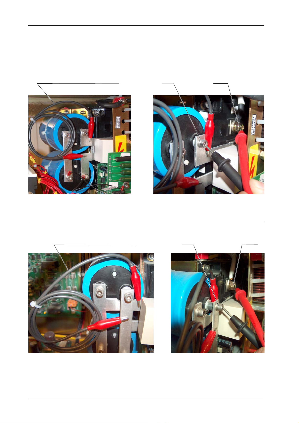
4. When Leds are off make a jumper between DC-BUS+ and DC--BUS-- . Make sure that there is
less than 10 VDC across the BUS. (Refer to Illustration 4-1 to see where to make the jumper).
5. Measure with a Multimeter in Diode (or ohms) between C2E1 (positive polarity) and E2 or C1
(negative polarity) in both IGBTs (refer to Illustration 4-1 for more details). Repeat the measure
with different polarity between C2E1 (negative polarity) and E2 or C1 (positive polarity).
Voltage should be around 0.3 V (or the resistance must be a high impedance) for the IGBT to
be OK. Normally when an IGBT is broken the voltage is = 0 volts (or theresistance is zeroOhms)
or very close.
TR-1005R4
35
Page 40
HF Series Generators
Troubleshooting
Illustration 4-1
Jumper and Measurement Points
C2E1E2Jumper between DC-BUS+ and DC-BUS--
3-- PHASE LINE POWERED GENERATOR
Jumper between DC-BUS+ and DC-BUS--
C2E1E2
1--PHASE LINE POWERED GENERATOR, BATTERY POWERED GENERATOR OR CAPACITOR ASSISTED GENERATOR
36
TR-1005R4
Page 41

6. Repeat the measurements done in step 5 for the other IGBT.
HF Series Generators
Troubleshooting
Note .
Don’t forget to remove the jumper across the DC Bus after all measurements are
made, otherwise the Inverter will suffer serious damage.
7. If any of the IGBTs are short-circuited, replace the IGBT.
8. If both IGBTs are OK, remove both shielded cable that connect the Inverter to the HV
Transformer: P1, P3 and SHLD (P2) . Isolate the three wires completely from each other and
from the metal sheet or ground. Make sure that wires are perfectly isolated and that no
short-circuit is made otherwise serious damages could result.
9. Set Dip-switch 3000SW2--2 in ON position at the HT Controller Board.
10. Turn ON mains and Generator.
11. Make an exposure:
G If “E09” or “Generator Overload” appear or the exposure has not been cut before 80ms,
change (if possible) the whole Inverter. If it is not possible check capacitor C9 and choke
L1 of the inverter (normally placed at the backside of the inverter). If both seem OK, change
both IGBTS and IPM Drivers (Do not forget to re--connect both shielded cables to the HV
Transformer (P1, P2 and P3).
G If “E09” or “Generator Overload“ does not appear and the exposure has not been cut before
80 ms, re--connect both shielded cables to the H. Voltage Transformer (P1, P2 and P3).
Follow the procedure in paragraph C (High Voltage Transformer Test).
Note .
At the end of an Exposure and right after releasing the Handswitch, error “E13” is
shown on the Console (this is normal, reset and continue
12. Turn OFF mains and Generator.
13. Set Dip-switch 3000SW2-2 in OFF position at the HT Controller Board. Re-connect both
shielded cables that connect the Inverter to the HV Transformer P1, P3 and SHLD (P2).
).
TR-1005R4
37
Page 42
HF Series Generators
Troubleshooting
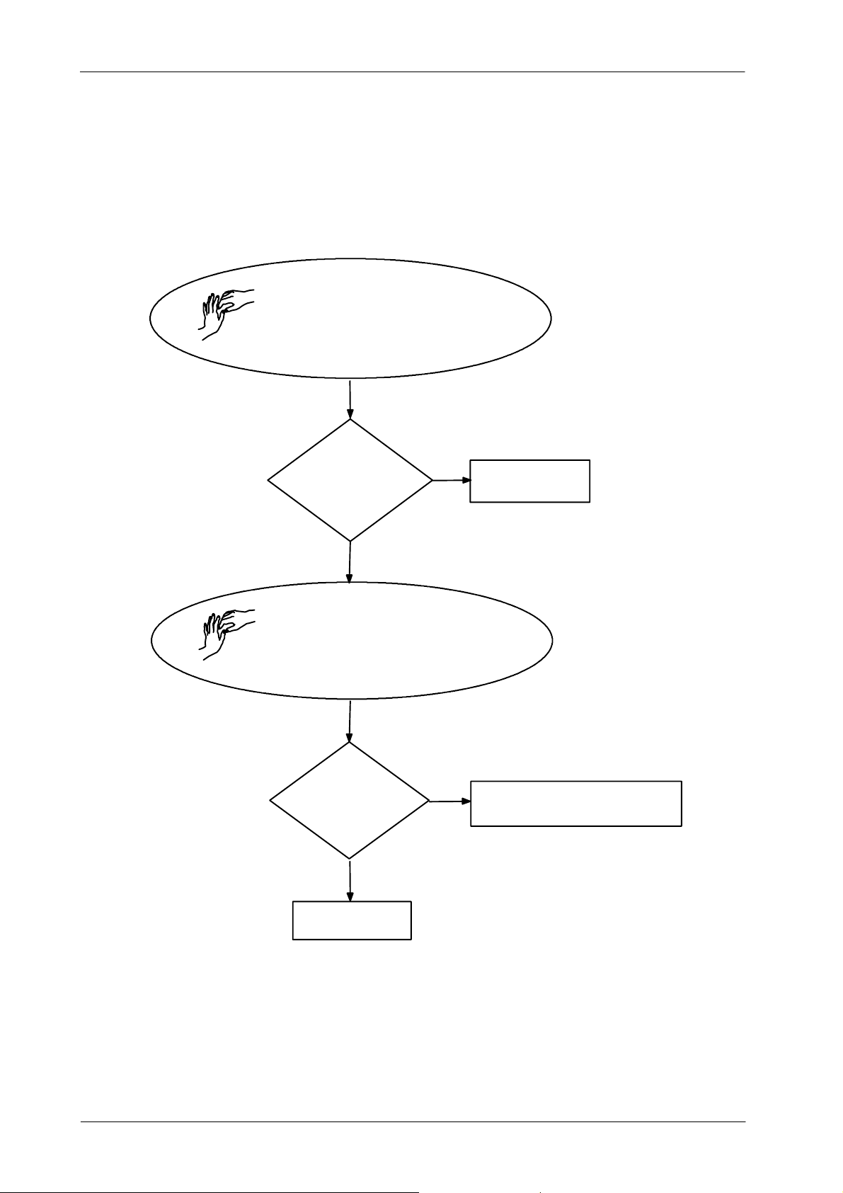
Illustration 4-2
Flowchart for B: Inverter Module Test
TURN OFF GENERATOR
WAIT TILL INVERTER IS DISCHARGED
MAKE A JUMPER DC--BUS+ AND DC--BUS--
MEASURE AND CHECK
V¶ 0,3V
YES
REMOVE JUMPER DC--BUS
REMOVE SHIELDED CABLES THAT CONNECT
INVERTER TO THE HV TRANSFORMER
SET 3000SW2-2=ON
TURN ON GENERATOR & MAKE EXPOSURE
NO
E09 OR
EXPOSITION CUT ?
NO
REPLACE IGBT
RE--CONNECT H V TRANSFORMER AND IN-
VERTER PERFORM C:HV TRANSFORMER TEST
38
YES
REPLACE INVERTER
TR-1005R4
Page 43
HF Series Generators
Troubleshooting
C. HV TRANSFORMER TEST
1. Connect the scope as follows:
G CH.1 on + mA (TP14) on HT Controller Board.
G CH.2 on - mA (TP13) on HT Controller Board.
G Base Time in 10 ms per division and 1 V per division
2. Turn ON mains and Generator. Set Dip-switch 3000SW2-4 in ON position at the HV Controller
Board. Select 50 kVp, 25 mA and 50 ms.
3. Make an exposure and check that both waveforms are almost symmetric (a difference of ±10%
is normal).
G If it is OK, follow procedure in step-4.
G If it is not OK, check:
-- that in the mA Test Point of the HV Transformer the jumper is correctly placed and
secure.
-- that connector J1 is correctly placed and secure in the HV Transformer.
-- continuity between J1-D and P4-7, J1-E and P4-6, J1-BandP4-2, and J1-C and P4-1.
Check that they are correctly connected and secure.
-- if after these actions the waveform is not OK, replace HV Transformer.
4. Turn OFF Generator and mains.
5. Remove HV Cables from the HV Transformer (anode and cathode) and fill the HV Receptacles
with oil.
6. On the HT Controller Board, make a jumper FIL (TP8) and + 5 V (TP2).
7. Turn ON mains and Generator. Select 50 kVp, 50 mA and 50 ms.
8. Connect the scope as following:
G CH.1 on + kV (TP11) on HT Controller Board.
G CH.2 on -- kV (TP12) on HT Controller Board.
G Base time in 10 msec. per division and 2 V per division.
9. Make an Exposure and check that both waveforms are symmetric.
10. Make exposures from 50 kVp to 110 kVp with the same Exposure Time and check that all kVp
waveform are symmetric and the values are similar according the table below.
TP11 & TP12
Select
50 kVp 2.1 V
on the HT Controller
(Compact Generators)
TR-1005R4
70 kVp 2.9 V
90 kVp 3.7 V
110 k Vp 4.5 V
130 kVp (only for 150 kVp HV Transf.) 5.3 V
39
Page 44

HF Series Generators
Troubleshooting
11. Select the maximum kVp allowed (depending on the tube type) and maximum Exposure Time
allowed but NEVER
waveforms are correct. If the waveforms are not symmetric within ± 10% at any point, replace
the HV Transformer.
12. Repeat the above procedure for the X-ray Tube-2 if the room has two tubes.
13. If everything is OK, it means that HV Transformer is OK and the problem could be in the X-ray
Tube or in the HV Cables. To know when the Tube begins to arc follow procedure in parragraph
D. At any case, X-ray Tube must be replaced.
14. Set on the HT Controller Dip-switch SW2 position 4 in OFF and remove jumper between FIL
(TP8) and + 5 V (TP2).
D. X-RAY TUBE TEST
After the performance of the above referred test everything is found OK, the Service Engineer may
want to know the actual status of the tube. Perform the following procedure in order to determine the
point in which the X-ray Tube begins to arc, it is strongly recommended to replace the tube as soon
as possible to prevent potential damage to the Generator.
1. Select minimum kVp and minimum mA and 100 ms.
2. Make an exposure.
3. Increment kVp in 10 kVp steps, select same mA and time. Make an exposure.
G If “E09” or “Generator Overload” appears follow procedure in step C.1 (HV Transformer
Test) .
G If not, keep on incrementing the kVp in steps of 10 kVp (60, 70, 80, 90, 100, 110, 120 and
125 kVp for 125 kVp HV Transformers; and 130, 140, 150 kVp HV Transformers) making
exposures at each kVp selected.
-- If “E09” or “Generator Overload” appears at any kVp selected it means that the tube
has dielectric problems above the selected kVp.
• If “E09” or “Generator Overload” does not appear up to maximum kVp, it means that arcing may
be due to mA or kW, follow procedure in step-4.
4. Select minimum kVp and minimum mA. Increment the mA one station and make an Exposure.
Keep on incrementing the mA station (making exposures) until “E09” or “Generator Overload”
appears. This will give an idea of the maximum mA allowed by the tube without arcing. If “E09”
or “Generator Overload” does not appear follow step-5.
5. If the tube still does not arc, the problem is related to kW=KV*mA. Make selections on the
Console at 100 ms incrementing kVand mA. A point will be reached in which “E09” or “Generator
Overload” will appear. This will give an idea on the approximate value of kVp and mA that can
be handled by the X-ray Tube. Also, this value may change when the tube heats up.
go over the 110-- 130 kVp limit. Make several Exposures and check that
40
E. RANDOM “E09” OR “GENERATOR OVERLOAD”
If everything is OK and random “E09” or “Generator Overload” appears, check:
1. That the signal IGBT FAULT on Pin 3 of P5 on the HT Controller Board is not low (logic 0) in
stand-by and during the exposure. If there is noise, check loose connection between Pin 3 of
P5 on HT Controller Board, and Pin 4 of J2 in both IPM Driver Boards
2. If IGBT FAUL T is active during an exposure, try to isolate when it occurs. It may be due to noise
coming from any device outside the Generator (Bucky, Fluoro devices, etc.). Or it may occur
when selecting a high power Exposure and the voltage of the main line goes down more than
10% (in this case check the part number of the IPM DriverBoard, it must be A3063-03 or greater).
TR-1005R4
Page 45

HF Series Generators
Troubleshooting
ERROR CODE : E10
DESCRIPTION : EEPROM corrupted or not initialized on ATP Console CPU Board or on HT Controller Board.
Wrong data calibration.
ERROR TYPE : Fatal Error during power up (when EEPROM U3 on HT Controller Board is corrupted or not
APPLICABLE TO : All Generators.
APPEARS WHEN : Only during initialization phase.
INFORMATION / SYMPTOM : Generator does not continue with start up.
POSIBLE CAUSES
initialized).
Informative error during power up (when EEPROM U18 on ATP Console Board is corrupted or not
initialized or when EPROM U24 on ATP Console Board has been changed). In both cases, “E10”
appears together with “E34” Error Code or “T echnique Error” indication.
EEPROM U3 on HT Controller Board corrupted or no initialized.
EEPROM U18 on ATP Console Board corrupted or no initialized.
EPROM U24 on ATP Console Board has been changed.
ACTIONS
1. If EPROM U24 in the ATP Console Board has been replaced, reset the Error Code to
acknowledge that the NVRAM has been initialized.
2. If the error does not reset, turn the Generator OFF and set Dip-switch A3024SW2-3 in ON
position to allow Service Mode. Turn the Generator ON and enter in workstations configuration
and check as referred in Service Manual (do not forget to exit from Configuration mode to store
the workstation configuration).
3. If the problem is still present, and “E10” error appears together with “E34” Error Code or
“Technique Error” indication, replace ATP Console Board.
4. If the problem is still present and only “E10” error appears on the Console, replace HT Controller
Board.
TR-1005R4
41
Page 46

HF Series Generators
Troubleshooting
ERROR CODE : E11
DESCRIPTION : No voltage in the Capacitor Bank.
ERROR TYPE : Informative. “Prep” is not allowed.
APPLICABLE TO : All Generators
APPEARS WHEN : Only during initialization phase or when pressing “PREP”.
INFORMATION / SYMPTOM : It was not possible to perform “Prep” or “Exp”.
POSIBLE CAUSES
No voltage in the Capacitor Bank (5C1, 5C2, 5C3, 5C4) of the Generator Cabinet.
Defective Charge/Discharge Monitor Board.
Precharge K6 contactor located inside the Generator Cabinet is not energized.
Main line fuses F3 and/or F4 are blown.
“--CHRG” signal of Pin 7 on connector P1 on HT Controller Board is not present.
Exposition parameters selected above IGBT maximum current (only software versions before
V2.R06)
Cables disconnected accidentally or damaged connectors.
Test Switch SW1 of the Generator Cabinet is in “Test” position (only for Factory use). This is only
applicable to old Generators.
ACTIONS
A. IF LED DS1 IN CHARGE/DISCHARGE MONITOR LIGHTS
Check Capacitors Voltage,
• If it is OK, check that P1-7 on HT Controller is at logic level “0”. (0.75 V for Generators with 1
Charge/ Discharge Monitor Board and 1.5 V for Generators with 2 Charge/Discharge Monitor
Boards).
G If it is OK (logic level 0), replace HT Controller Board.
G If it is not OK, check links between P1-7 on HT Controller Board and P1-2 in
Charge/Discharge Monitor Board #1 and P1-1 in Charge/Discharge Monitor Board #1 and
P1-2 in Charge/Discharge Monitor Board #2,
-- If it is OK, replace defective Charge/Discharge Monitor Board.
-- If it is not OK, repair connection.
• If voltage in capacitors is not OK, check VAC on AC1, AC2 and AC3 at Input Rectifier Board (for
Battery Powered Generators check battery voltage).
G If VAC is not OK, verify input connections and input fuses.
G If VAC is OK, disconnect BUS+ and BUS-- at Input Rectifier Board and check VDC.
-- If VDC is not OK, replace defective component (CR1, CR2, CR3) at Input Rectifier
Board.
-- If VDC is OK, check and replace defective component at Generator Cabinet.
42
TR-1005R4
Page 47

HF Series Generators
Troubleshooting
B. IF LED DS1 DOES NOT LIGHT AND IT IS NOT A BATTERY POWERED GENERATOR.
• Check input VAC on 6LF1,
G If VAC is OK, replace a defective component at Input Rectifier Board (CR2, CR3 or CR1).
G If VAC on 6LF1 is not OK, check that contactor 6K5 is ON.
-- If 6K5 is ON, check VAC on T1,T2 and T3 (in 6K5).
-- If voltage is OK, replace defective 6R1.
-- If voltage is not OK, replace the defective fuse (F3, F4 or F5).
• If Contactor 6K5 is not ON, check if signal +24VPSU is OK.
G If it is not OK, check and/or replace 3F6 and 6T2.
G If +24VPSU is OK, check that signal -- LINE CONT is at 0 VDC,
-- if --LINE CONT is OK, replace 6K5.
-- If --LINE CONT is not OK, check continuity in J3-10 at ATP Console Board.
-- If --LINE CONT is OK at ATP Console Board, repair connection between J3-10
and “A” in 6K5.
-- If -- LINE CONT is not OK at ATP Console Board, replace ATP Console Board.
C. IF LED DS1 LIGHTS AND IT IS A BATTERY POWERED GENERATOR.
Check Contactor 6K5,
• If 6K5 is ON, check output voltage of 6K5.
G If 6K5 output voltage is OK, replace defective 6R1.
G If 6K5 output voltage is not OK, check and replace 6F1, 6J1 and Andersen connectors.
• If 6K5 is not ON, check if signal +24VPSU is OK.
G If it is not OK, check and/or replace 3F6 and 6T2.
G If +24VPSU is OK, check that signal -- LINE CONT is at 0 VDC on J3-10 at ATP Console
Board,
-- if --LINE CONT is OK, replace 6K5.
-- If --LINE CONT is not OK, check continuity in J3-10 at ATP Console Board.
-- If --LINE CONT is OK at ATP Console Board, repair connection between J3-10
and “A” in 6K5.
-- If -- LINE CONT is not OK at ATP Console Board, replace ATP Console Board.
D. IF LED DS1 DOES NOT LIGHT AND IT IS A BATTERY POWERED GENERATOR.
Check Contactor 6K5,
• If 6K5 is ON, check output voltage of 6K5.
G If 6K5 output voltage is OK, replace defective 6R1.
G If 6K5 output voltage is not OK, check and replace 6F1, 6J1 and Andersen connectors.
TR-1005R4
• If 6K5 is not ON, check if signal +24VPSU is OK.
G If it is not OK, check and/or replace 3F6 and 6T2.
G If +24VPSU is OK, check that signal -- LINE CONT is at 0 VDC on J3-10 at ATP Console
Board,
-- If --LINE CONT is OK at ATP Console Board, repair connection between J3-10 and
“A” in 6K5.
-- If -- LINE CONT is not OK at ATP Console Board, replace ATP Console Board.
43
Page 48

HF Series Generators
Troubleshooting
ERROR CODE : E12
DESCRIPTION : No mA during exposure or mA out of tolerance. Wrong filament current.
ERROR TYPE : Informative.
APPLICABLE TO : All Generators
APPEARS WHEN : After exposition.
INFORMATION / SYMPTOM : Error 12 appears after the Exposure to alert the operator that the mA at the start of the exposure has
POSIBLE CAUSES
not been correct. During the first 10 ms the Generator applies constant filament current to the tube.
This current is proportional to the current already calibratedfor that mA station at the kVp selected for
that Exposure (filament numbers). Near the end of these10 ms, the HT Controller reads the mA and if
they are found to be 30% under or over what has been selected, it sends error 12 to the Console.
Calibration data for kVp and mA is not correct causing error E12.
The mA jumper on the HV Transformer is open, or it is not making good contact. The mA read at the
beginning of the exposure is 50% of the correct value (because one branch is open).
There is a problem on the reading of the mA.
No correct heating prior to the Exposure. The filament has not reached its correct temperature and
the mA at the start of the exposure is low. It usually occurs when the “Prep” and “Exp” buttons are
pressed down at the same time.
Making an exposure immediately after getting out of calibration mode in extended memory.
+5 VDC , +12 VDC or --12VDC Power Supplies of HT Control Board (mesured at TP2, TP3 and TP4
of this Board) have excesive ripple or VDC measured is not correct.
ACTIONS
1. Connect a scope to thefollowing Test Points on the HT Control Boardand check that the voltage
is correct, if not adjust it with the respective Potentiometer in the Power Supply Board (refer to
Section 2.1 -- Low DC Voltage Power Supply Test):
TP2 (+5 VDC) on HT Control Board is adjusted with R12 Pot. in the Power Supply Board.
TP3 (+12 VDC) on HT Control Board is adjusted with R26 Pot. in the Power Supply Board.
TP4 (--12 VDC) on HT Control Board is adjusted with R25 Pot. in the Power Supply Board.
2. Check calibration data for the mA Open Loop (filament numbers) as stated in the Service Manual
for all combinations of kVp and mA when this error appears.
With a scope connected to the Test Point TP5 (mA) on the HT Control Board check that the mA
read is within the ratio of 1V=100 mA (± 5%) for V2 and V3 software versions, for V4 and up the
ratio is 1V=10mA from minimum mA to 80 mA and 1V=100mA from 100 mA to the maximum
rating. If it is not, the cause could be that the mA second test is not measuring correctly, or a
wrong measurement performed in the Generator. (Refer to step 3).
3. Check that the jumper in the mA Test Point of the HV Transformer is correctly placed and secure.
4. With a scope check thatduring the entire Exposure signals on TestPoints TP13 (-- mA) and TP14
(+mA) on the HT Control Board connectors are symmetrical (± 10%). If one is found missing or
not symmetrical, measure on Pin 6 and 7 of J4 on the HT Control Board. If they are symmetrical
on both Points, the problem could be on the HT Control Board. If they are not correct, check that
the connections made on the HV Transformer in J1-E, D, K terminals for Compact Generators
(in TB1, terminals 1, 4 and 5 for no Compact Generators) are correctly connected and secure.
Also check that the GND wire is connected to GND stud. If connections are correct the problem
is in the HV Transformer.
44
TR-1005R4
Page 49
ERROR CODE : E13
HF Series Generators
Troubleshooting
5. Connect a scope to Test Point TP5 (mA) on the HT Control Board. Check that when an exposure
is made by pressing at the same time the “Prep” and “Exp” controls, the mA at the beginning of
exposure is low. Check that when the exposure is made by pressing first the “Prep” control and
then the “Exp” control, the mA at the beginning of exposure is correct.
6. For Low Speed Generators:
G Reprogram the “Rotor Acceleration and Filament Setting Time” as stated in the Service
Manual, one step over the time as it was before (a.e.: if it was 1.2 seconds, reprogram for
1.8 seconds) and check if boosting is correctly configured.
7. For High Speed Generators:
G When performing the test for High Speed Generators check that the self-maintaining mode
is not active. In order to check if the problem disappears, select the highest mA station for
Small Focus and the lowest kVp allowed for this mA station (a.e. 40 kVp, 150 mA, SF).
Make an Exposure by pressing at the same time the ”Prep” and “Exp” controls; check that
the mA reading at the beginning of the Exposure is correct. Do the same for Large Focus
(a.e. 50 kVp, 500 mA, LF). If it is not correct, reprogram a step over at the time for each case,
and test again.
DESCRIPTION : No kVp during exposure or kVp out of tolerance.
ERROR TYPE : Informative. May abort exposition.
APPLICABLE TO : All Generators
APPEARS WHEN : During and after exposures.
INFORMATION / SYMPTOM : No kVp during exposure.
POSIBLE CAUSES
Note .
This error assumes that the fault is not on the IGBT and is not due to arcing in the
X-ray Tube.
Defective HV Transformer.
Defective HT Controller Board.
Defective IPM Driver Boards.
Poor connection on the IPM Driver Boards.
ACTIONS
1. Check 5 VDC between P1-4 and P1-3 (GND) in both IPM Driver Boards.
2. Check 115 VAC between Pins 1 and 2 of connector P2 on the same Boards.
3. If it is OK, check if the -kVp (TP12) and +kVp (TP 11) Test Points on the HT Controller Board
are symmetrical. If they are not, check signals -- kV and + kV (in Compact Generators between
P4-1 and J1-B at HV Transformer and also between P4-2 and J1-C at HV Transformer) (in no
Compact Generators between P4-1 and TB1-3 at HV Transformer and also between P4-2 and
TB1- 4at HV Transformer) if they are OK, replace the HV Transformer.
4. Check the connectors on the IPM Driver Boards. Check continuity in P3-1 (-kV DR1), P3-2
(-- kVDR2) and those signals in IPM Driver Boards. Check with a scope in TP17 (1V=33.33kVp),
if value is OK, replace HT Controller Board; if value is not OK, replace IPM Driver Boards.
5. If kVp value and time is OK and “E13” appears, check that for software version V3 and up the
Dip-switches of A3024SW3 are all in OFF position at ATP Console Board.
TR-1005R4
45
Page 50

HF Series Generators
Troubleshooting
ERROR CODE : E14
DESCRIPTION : Exposure signal without X-ray Exposure Console command.
ERROR TYPE : Informative.
APPLICABLE TO : All Generators
APPEARS WHEN : During and after exposition.
INFORMATION / SYMPTOM : Exposure signal without X-ray Exposure Console command.
POSIBLE CAUSES
The “Exp” signal is grounding on the HT Controller Board.
ACTIONS
1. Remove the connector J1 on HT Controller Board and check grounding of Pin 6 of P1.
2. If so, replace the HT Controller Board.
3. If it is not, remove the connector J3 on the Console, and check Pin 1 on connector J3 on the
Generator Cabinet.
4. If GND, replace the communication cable J3; if not, replace the ATP Console Board.
ERROR CODE : E15
DESCRIPTION : No current on Filament. Wrong selection of Focal Spot detected during “Prep”.
ERROR TYPE : Informative. Does not allow “Prep”.
APPLICABLE TO : All Generators
APPEARS WHEN : At any moment.
INFORMATION / SYMPTOM : No current detected on Focal Spot (Filaments Off).
POSIBLE CAUSES
A -- There is no power supplied to the Filament Board or poor connection on the Cathode HV Cable
or defective Filament Transformer inside the HV Transformer or defective HV Switch inside the HV
Transformer (if the system is equipped with two tubes)
B -- Wrong signal --FIL1 ACK
46
TR-1005R4
Page 51

ACTIONS
HF Series Generators
Troubleshooting
A. THERE IS NOT SUPPLY IN FILAMENT BOARD, OR POOR CONNECTION ON THE
CATHODE HV CABLE, OR DEFECTIVE FILAMENT TRANSFORMER, OR DEFECTIVE HV
SWITCH.
Note .
For Generators with two tubes:
-- if the error appears in both tubes, go to step 1.
-- if the error appears in only one tube, interchange HV Cables.
-- if error remains when selecting the same tube from Console, replace HV
Transformer, if does not appear go to step 8.
1. Check through the X-ray tube window to see if the selected filament is On. Check both circuits
to detect which one is causing the error code.
2. If none lit when selected, check in the DC output on the BR1 rectifier (324 Dc approx.) or input
voltage (220 VAC approx.). If input voltage is OK and output voltage is not OK, replace rectifier.
If it is OK go to step 3.
3. Check if the Led’s DS1 and DS2 are lit ON in the Filament Board. If they are not, replace the
Board.
4. If everything is OK, check DC voltage between P2-4 and P2-1 (324 DC approx.). If not enough
voltage detected, review circuit between BR1 and T2 transformer. Replace Filament Board if
defective.
5. If it is OK, check the AC voltage between Pin 4 on connector P3 (on Filament Board Fil. Sup.)
and Pins 15 or 16 (depends on filament selection) on connector P4 on Interface Control Board.
The range should be between 90 and 200 VAC.
6. If not, check the voltage on Pin 17 of connector P4 at Interface Control Board and Pin 4 of
connector P3 at Filament Board, also Check P14 of connector P4. If no voltage present, replace
the Interface Control Board.
7. If it is OK, check continuity between HV Transformer connector and Interface Board.
8. If it is OK, check continuity of HV Cable connector (between common C and S (Small Focus)
and between common C and L (Large focus). The OHM value should be very low in both cases
( 0.01 approx.)
9. If it is OK, replace the HV Transformer. If it is not OK, check all connections from HV Cable to
the tube. Replace cable if necessary.
10. If HV Cable is OK, check tube filaments. Replace Tube if necessary.
TR-1005R4
47
Page 52
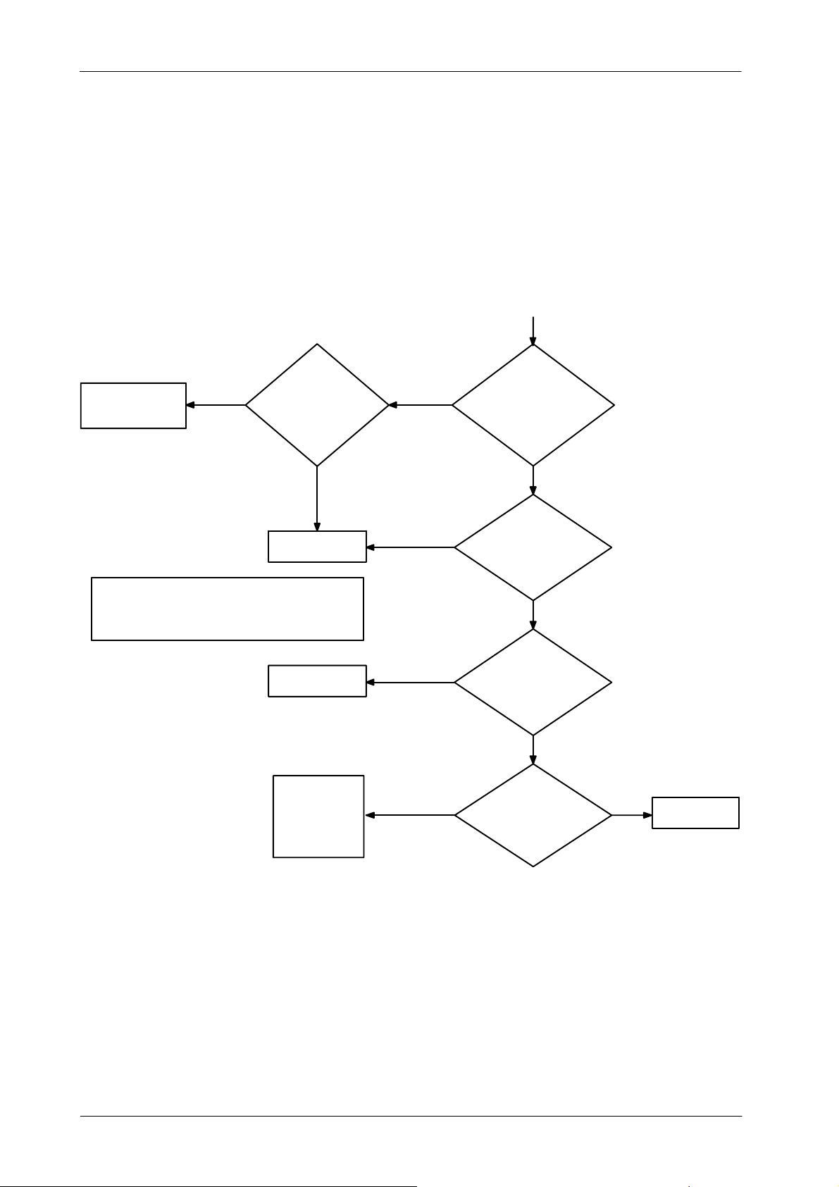
HF Series Generators
Troubleshooting
B. WRONG SIGNAL -- FIL1 ACK
Perform the following diagnosis if after pressing “Prep” the Error Code “E15” appears on the Console
and after reseting it, the Console displays Error Code “E04”.
START
Check and REPAIR
link P1-8 HT Controller
& P4-22 Interface Board
NOTES
1) FIL1 is Small Focus in Tube1 and it is Large Focus in Tube2.
2) FIL1 S LC is activated when selecting FIL1 during Stand by
for RAD Tubes. For R&F Tubes it is activated at “Prep”.
NO
Check -- FIL1 ACK
at Interface Board in
P1-8 at HT Controller.
Is it ok?
Replace
HT Controller Board
Replace
Interface Board
Check and fix
link P1-13 in
HT Controller
with P4 --19 in
Interface Board
YES
YES
YES
YES
YES
Press “Prep”
and check -- FIL1 ACK at
Interface Board (P4-22).
Is it Low Level?
NO
Check if K7
is ac ti ve when
selecting FIL1*.
Press Prep?
Is it active?
NO
Check signal
FIL1 SLC at P4-19
Interface Board.
Is it at Low Level when
selecting FIL1*?
NO
Check Si gnal -- FIL1
SCL in P1-13 at HT
Controll. Is it OK?
NO
Replace
HT Controller Board
48
TR-1005R4
Page 53
ERROR CODE : E16
DESCRIPTION : Invalid value of : kVp, mA or kW.
ERROR TYPE : Informative. Does not allow “Prep”or“Exp”.
APPLICABLE TO : All Generators
APPEARS WHEN : In “Prep”
INFORMATION / SYMPTOM : Selected mA or kVp are not correct.
POSIBLE CAUSES
Wrong maximum kVp configuration.
Wrong software compatibility on the Generator Cabinet and Console.
When pressing “Prep” during calibration of Open Loop mA with a technique that overpasses the
Generator power kVp/mA.
HF Series Generators
Troubleshooting
ACTIONS
1. Check switch 5 of SW2 on HT Controller Board (125 kVp in open position and 150 kVp in closed
position).
2. Check the software version on U5 of HT Controller Board and U24 of ATP Console Board.
3. Set calibration data manually as per calibration procedure table “mA calibration number change”
at calibration section in this manual.
ERROR CODE : E17
DESCRIPTION : Communication error between ATP Console CPU Board and HT Controller Board.
ERROR TYPE : Fatal Error. Generator opens line contactor that remains in a endless loop.
APPLICABLE TO : All Generators
APPEARS WHEN : Once initialization phase is over at any moment.
INFORMATION / SYMPTOM : No communication link between Console and Generator Cabinet.
POSIBLE CAUSES
Defective communication cable between Console and Generator Cabinet (J3).
Noise on the bucky circuitry.
Defective HT Controller Board or defective ATP Console Board.
The “Prep” signal from Console to HT Controller is short--circuited to ground.
ACTIONS
TR-1005R4
1. Turn Generator OFF/ON.
2. If E01 appears, follow procedure for E01.
3. If E01 does not appear, it is an intermittent error due an external device, install a R--C filter in the
power supply and at bucky start circuitry.
4. If error persists, replace HT Controller or ATP Console Boards.
49
Page 54
HF Series Generators
Troubleshooting
ERROR CODE : E18 OR ROTOR ERROR
DESCRIPTION : Rotor running without order or Rotor error.
ERROR TYPE : Fatal Error. Generator opens line contactor that remains in a endless loop.
APPLICABLE TO : All Generators
APPEARS WHEN : At any moment.
INFORMATION / SYMPTOM : The X-ray tube is not rotating while “Prep” is active, then the exposures are inhibited or the X-ray
POSIBLE CAUSES
tube anode is rotating without Console command.
Defective relay K1 (solid State) on the low speed module.
Signal –RTR on HT Controller Board is active.
Defective HT Controller or Low Speed Control Boards.
± 12 VDC power supplies missing on HT Controller Board.
ACTIONS
In Stand-by:
1. Check if the signal RTR Test Point (TP6 on HT Controller ) is logic “0”. If yes, check if K1 works
properly.
2. If it is OK, check if the ± 12 VDC power supplies are correct.
3. If it is OK, replace the H. T. Controller.
4. If not logic “0” check K1 at Low Speed Module.
5. If K1 defective, replace.
In “Prep”:
When Console has not “ Rotor Error” indication , E18 Appears.
(Rotor error/E18).
50
TR-1005R4
Page 55
IF E18 OR ROTOR ERRORAPPEARS IN “PREP”(ONLYFOR LF-RAC
)
VISUALLY CHECK
CHECK
TUBE STATOR
THAT ANODE IS
TURNING WHEN
PRESSING “PREP”
DOES IT TURN?
NO
YES
HF Series Generators
Troubleshooting
VERIFY STARTER IS CONFIGURED TO
CORRECT TUBE AND CAPACITOR
INSTALLED.
+
VERIFY AT SIGNAL DELAYED +24V THAT
LINE VOLTAGE IS TOO LOW -- THAT MAY
CAUSE ROTOR ERROR OR E18.
+
CHECK WITH THE SCOPE SIGNAL RTRI
AT TP6 HT CONTROLLER. SEE
ILLUSTRATION BELOW.
YES
CHECK
LINK
FROM TS2
TO TU BE
STATOR
IS IT OK?
NO
REPAIR CONNECTIONS
REPLACE FUSE 6F6
YES
YES
CHECK VAC ON TS2 --
CONNECTIONSSTATOR
PRESSING “PREP” IS IT
OK?
NO
CHECK SIGNAL
+24 DELAYED
IS IT OK?
NO
2.2 V
PREP
0.8
running
t
tprep
REPLACE K1 OR
LF--RAC BOARD
YES
CHECK IF -START &--ACC
ARE AT LOW LOGIC LEVEL WHEN
NO
REPEAT CONFIGURATION OF
ROTOR ACCELERATION TIME
FOR LOW SPEED
PRESSING PREP
TR-1005R4
51
Page 56
HF Series Generators
Troubleshooting
ERROR CODE : E19
DESCRIPTION : mA detected without “Exp” command.
ERROR TYPE : Fatal Error. Generator opens line contactor that remains in a endless loop. It is necessary to turn
APPLICABLE TO : All Generators
APPEARS WHEN : In stand-by or during initialization.
INFORMATION / SYMPTOM : Current in tube without ”Prep” command.
POSIBLE CAUSES
off the equipment.
± 12 VDC power supplies missing on the H. T. Controller Board.
Defective H. T. Controller.
mA signal on H T Controller is active.
ACTIONS
1. Check ± 12 VDC power supplies.
2. Check a logic level “0” in TP5. Check also a level logic “0” in TP13, TP14 connector P4-6 y P4-7.
3. If it is OK, replace the HT Controller or Filament Drive Boards one by one.
ERROR CODE : E20
DESCRIPTION : kVp detected without “Exp” command.
ERROR TYPE : Fatal Error. Generator opens line contactor that remains in a endless loop.
APPLICABLE TO : All Generators.
APPEARS WHEN : In stand-by or during initialization.
INFORMATION / SYMPTOM : kVp detected without “Exp” command.
When E20 appears on Console (E20) means that the error can not be solved without turning off the
equipment.
POSIBLE CAUSES
--12 VDC power supply missing.
Defective HT Controller Board.
ACTIONS
52
1. Check -- 12 VDC power supply.
2. Check logic level “0” in TP7 and TP11, TP12, P4-1 and P4-2.
3. If it is OK, replace HT Controller Board.
TR-1005R4
Page 57

HF Series Generators
Troubleshooting
ERROR CODE : E21
DESCRIPTION : Wrong Tube-1 selection.
ERROR TYPE : Informative. Does not allow working unless the error is solved or other tube is selected.
APPLICABLE TO : All Generators.
APPEARS WHEN : At any moment mainly after initialization or when changing tube selection.
INFORMATION / SYMPTOM : Wrong tube 1 selection.
POSIBLE CAUSES
The –HT INTLK is not grounding (tube 1 selection).
Defective HV Switch inside the HV Transformer (two tubes option).
The --HT INTLK is missing.
ACTIONS
Only for one tube option (no Compact Generators):
1. Check signal –HT INTLK on Pin 9 of TB1 in the HV Transformer, it should be 0 VDC on tube 1
selection.
2. If it is not OK, check Pin 9 of TB1 and verify that ground is 0 Ω. If it is not, replace the HV
Transformer.
3. If it is OK, check signal -HT LINK on ATP Console Board (J3-13), if not “0” in J3-13, check link
between TB1-9 and J3-13, if voltage = “0” and E21 appears, replace ATP Console Board.
Only for one tube option (Compact Generators):
1. Check the –HT INTLK in 6J3-13 (Generator Cabinet), it should be “0” VDC on tube 1 selection.
2. If it is not OK, check Jumper between 6J3-13 and 6J3-16 (GND).
3. If 6J3-13 = 0, check 6J3--13 on ATP Console Board.
4. If not “0” in J3-13, checklink between TB1-9 and J3-13, if voltage = “0” and E21 appears, replace
ATP Console Board.
Only for two tubes option (no Compact Generators):
1. Check the –HT INTLK on Pin 9 of TB1 in the HV Transformer, it should be 0 VDC on tube 1
selection.
2. If it is not OK, check between Pin 9 of TB1 and verify that ground is 0 Ω. If not replace the HV
Transformer.
3. If it is OK, check 0V at J2-13 on ATP Console.
a. If it is not OK, check between J3-13 on ATP and TB1-9.
b. If it is OK, replace ATP Console Board.
TR-1005R4
Only for two tubes option (Compact Generators):
1. Check logic “0” in J3-13 on ATP Console Board, if “0” VDC, replace ATP Console Board.
2. If not “0”, turn off equipment, disconnect J1 of HV Transformer and check continuity between
J1-J and J3-13 on ATP Console Board.
3. If it is not OK, check cable and replace if necessary.
4. If connection is OK, replace HV Transformer.
53
Page 58

HF Series Generators
Troubleshooting
ERROR CODE : E22
DESCRIPTION : Wrong Tube-2 selection.
ERROR TYPE : Informative. Does not allow working unless the error is solved or other tube is selected.
APPLICABLE TO : All Generators.
APPEARS WHEN : At any moment mainly after initialization or when changing tube selection.
INFORMATION / SYMPTOM : Wrong tube 2 selection.
POSIBLE CAUSES
The –HT INTLK is not high logic level 5V (tube 2 selection).
Defective HV Switch inside the HV Transformer (two tubes option).
The --HT INTLK is grounding.
ACTIONS
Only for one tube option (no Compact Generators):
1. Check signal –HT INTLK on Pin 9 of TB1 in the HV Transformer, it should be 5 VDC on tube 2
selection.
2. If it is not OK, check Pin 9 of TB1 and verify that ground is infinite Ω. If it is not, replace the HV
Transformer.
3. If it is OK, check signal -HT LINK on ATP Console Board (J3-13), if not “1” in J3-13, check link
between TB1-9 and J3-13, if voltage = “5” and E22 appears, replace ATP Console Board.
Only for one tube option (Compact Generators):
1. Check the –HT INTLK in 6J3-13 (Generator Cabinet), it should be “5” VDC on tube 2 selection.
2. If it is not OK, check that 6J3-13 is not grounding.
3. If 6J3-13 = 5, check 6J3--13 on ATP Console Board.
4. If not “5” in J3-13, checklink between TB1-9 and J3-13, if voltage = “5” and E22 appears, replace
ATP Console Board.
Only for two tubes option (no Compact Generators):
1. Check the –HT INTLK on Pin 9 of TB1 in the HV Transformer, it should be 5 VDC on tube 2
selection.
2. If it is not OK, check between Pin 9 of TB1 and verify that ground is infinite Ω. If not replace the
HV Transformer.
3. If it is OK, check 0V at J2-13 on ATP Console.
a. If J2-13 is not OK, check 5V between J3-13 on ATP and TB1-9.
b. If it is OK, replace ATP Console Board.
54
Only for two tubes option (Compact Generators):
1. Check logic “5” in J3-13 on ATP Console Board, if “5” VDC, replace ATP Console Board.
2. If not “5”, turn off equipment, disconnect J1 of HV Transformer and check continuity between
J1-J and J3-13 on ATP Console Board.
3. If it is not OK, check cable and replace if necessary.
4. If connection is OK, replace HV Transformer.
TR-1005R4
Page 59

HF Series Generators
Troubleshooting
ERROR CODE : E23
DESCRIPTION : Calibration data not stored
ERROR TYPE : Indicative although it is almost impossible to find if not provoked.
APPLICABLE TO : All Generators.
APPEARS WHEN : When trying to save a calibration data.
INFORMATION / SYMPTOM : Calibration data not stored. Calibration value intended to be stored has not been properly
POSIBLE CAUSES
recorded.
This problem may be shown randomly.
This problem is continuos or occurs frequently and the communication link between the Generator
Cabinet and the Console is too noisy .
ACTIONS
1. Store data again.
2. Check communication cables.
3. Route communication cables in a different way.
TR-1005R4
55
Page 60
HF Series Generators
Troubleshooting
ERROR CODE : E24
DESCRIPTION : The Bucky has not been detected to be moving.
ERROR TYPE : Indicative. Does not allow exposition.
APPLICABLE TO : All Generators.
APPEARS WHEN : At the beginning of exposition.
INFORMATION / SYMPTOM : Wrong Exposure signal from Buckies.
POSIBLE CAUSES
Malfunction of the bucky.
Wrong wiring of the bucky .
Wrong bucky selection.
ACTIONS
REPAIR
CONNECTION
REPLACE
INTERFACE BOARD
NO
YES
CHECK
-- DRCMA AT PREP
IS IT AT LOW
LEVEL?
YES
CHECK K2 FOR
BUCKY1&K3FOR
BUCKY 2
ARETHEYON?
YES
CHECK-BUCKY
MOTION 1&2 AT
INTERFACE BOARD
P4-11 & P4-10 AT LOW
LEVEL IS IT OK?
NO
REVIEW WORK STATION
CONFIGURATION
IS IT OK?
YES
CHECK
J3-14,J3-11 AT
ATP C ONS.
IS IT OK?
YES
CHECK AND REPAIR
LINK J3 --14 //P4-12 AT
INTERFACE BOARD
J3--11 / P4-13 AT
INTERFACE BOARD
NO
NO
CONFIGURE
CORRECTLY
REPLACE
ATP CONSOLE BOARD
56
NO
PROBLEM AT BUCKY
TR-1005R4
Page 61

HF Series Generators
Troubleshooting
ERROR CODE : E25
DESCRIPTION : Battery failure in Battery Powered Generators.
ERROR TYPE : Indicative. Does not allow exposition.
APPLICABLE TO : All Battery Powered Generators.
APPEARS WHEN : At “Prep” in any Battery Powered Generators and at any moment in Generators with Stand-Alone.
INFORMATION / SYMPTOM : Battery charge level is momentarily low or some batteries are discharged or damaged.
POSIBLE CAUSES
Batteries are discharged.
Some Battery Charger Sector is not working properly or some Batteries are damaged.
ACTIONS
A. PRELIMINARY
E25 appears when the Generator has not been used for a period of time, it usually allows 2 or 3
exposures and then E25 appears.
If this is the case, charge Batteries and perform exposures until the batteries are totally discharged,
then charge again and perform exposures again to discharge, repeat the procedure 5 or 6 times. This
is the way to charge batteries fully and safe.
B. BATTERIES FULLY CHARGED AND “E25” APPEARS
1. Check Corrosion in metal contacts of Batteries.
2. Check charger Leds on Battery Charger. Green Leds and LED DS1 should be ON.
3. Check vol ta ge in J1 of Battery Charger Board: J1-16 & J1-15, J1-14 & J1-13...... , J1-2 & J1-1.
• With Generator OFF and disconnected from Mains, the voltage to be found is: 26.6 VDC.
• With Stand-Alone mode, disconnected the Generator from Mains and with the Generator turned
On, the voltage should be: 25.4 VDC.
G If voltage is not OK, check the batteries status and replace defective batteries if needed
(refer to Section 2.6.2 -- Identifying and Replacing Defective Batteries).
G If total voltage is correct and E25 appears, check the measure circuit.
-- In Generators with Stand-Alone check links between J1-18 (HT Controller) & J3-5
(Stand-Alone), J1-19 (HT Controller) & J3-6 (Stand-Alone), J1-20 (HT Controller) &
J3-7 (Stand-Alone). If links are OK and batteries voltage is OK but signals are below
minimum required (that is --BA TST3 is “0”, BATST2 is “0” and BATST1 is “1”), check
HT Controller Board and Stand-Alone Board, replace the defective Board found.
-- For Generators without Stand-Alone check that signal -BAT FAULT at P5-2 of
HT Control Board is at “High Level”.
If -BAT FAULT is at “High Level”, replace HT Controller Board.
If -BAT FAULT is at “Low Level”, check J2-2 in Battery Charger Board. If not “Low
Level” replace cable. If “Low Level“ replace the Battery Charger Board.
TR-1005R4
57
Page 62

HF Series Generators
Troubleshooting
C. LEDs CHECKING ON THE BATTERY CHARGER BOARD
1. GREEN LEDS ARE ON BUT LED DS1 IS
OFF
Check that 24 V is present in J2-1 of Battery Charger Board.
• If it is OK, replace Battery Charger Board.
• If it is not OK, check 24V in J2-7 Line Monitor.
G If it is OK, repair links between J2-1 of Battery Charger Board & J2-7 of Line Monitor Board.
G If it is not OK, check 20 VAC between J2-5 and J2-6 at Line Monitor Board.
-- If it is OK, replace Line Monitor Board.
-- If it is not OK,check voltage from 2T1 Battery Charger Transformer to the Line Monitor
Board and replace it if necessary.
2. SOME GREEN LEDS ARE NOT ON AND DS1 IS
ON.
Check Fuses F7 to F21(2A, 250 VAC) (Charger Sectors) of the Battery Charger Board.
Check VAC at J6 and J4 in Battery Charger Board (connectors J6 and J4 must be plugged in the
Board), it should be 28 VAC (measure between: J6-1 & J6-2, J6-3 & J6-4........... until J6-15 & J6-16,
and also check J4-1 & J4-2 ........ until J4-13 & J4-14).
• If VAC is OK, replace Battery Charger Board.
• If VAC is not OK, unpplug connectors J6 and J4 from the Battery Charger Board and repeat the
measure checking VAC from 2T1 Battery Charger Transformer at connectors J6 and J4, it
should be 28 VAC (measure between: J6-1 & J6-2, J6-3 & J6-4........... until J6-15 & J6-16, and
also check J4-1 & J4-2 ........ until J4-13 & J4-14). Che ck 2T1 Battery Charger Transformer and
replace it if necessary.
3. NONE LED IS
ON
Check that Generator is Powered ON.
If DL1 is blinking (yellow) at Line Monitor Board and DL2 and DL3 are OFF
:
• Check VAC between J2-1 and J2-3 at Line Monitor Board.
G If no VAC found, replace Line Monitor Board.
G If VAC found, check VAC on 2T1 Battery Charger Transformer.
-- If no VAC found, check and fix connection at 2T1 Battery Charger Transformer.
-- If VAC found, check 2T1 Battery Charger Transformer.
If DL1 is blinking (yellow) at Line Monitor Board while DL2 and DL3 are ON (any of them)
:
• Check Line VAC +/- 15%.
G If Line VAC is not OK, it is an external problem.
G If Line VAC is OK, review the Line Monitor Board adjustment.
58
Line Monitor Boa rd Adjustment: Configure SW1 at Line Monitor Board according to
Power Line Voltage (refer to Installation chapter in Service Manual). Measure the Power
Line Voltage with a Digitalmeter and adjust VDC on TP2 with POT1 at Line Monitor Board
as per the following formula:
V
measured
V
nominal
× 2.5 = V
TP2
V
(measured:220V)
V
(nominal:230V)
× 2.5 = V
V measured is the real voltage obtained with polymeter.
V nominal is the SW1 configuration Voltage.
If all Leds are off at Line Monitor
Board:
• Check VAC on J2-1 / J2-2 at Line Monitor Board.
G If VAC is OK, review configuration of Jumper SW1.
G If VAC is not OK, check (Magnetothermic ) 1SW1 is ON and external VAC power.
(2.4VDC)Example:
TP2
TR-1005R4
Page 63
ERROR CODE : E26
DESCRIPTION : Voltage failure in Battery Powered Generators with Stand-Alone.
ERROR TYPE : Fatal error. System shut down.
APPLICABLE TO : All Battery Powered Generators with Stand-Alone.
APPEARS WHEN : At the beginning of exposition.
INFORMATION / SYMPTOM : System failure
POSIBLE CAUSES
No voltage detected at Stand Alone.
Shutdown
DC is below or over specifications
HT Controller cables are accidentally grounded.
HF Series Generators
Troubleshooting
ACTIONS
1. Check that DL4 is ON, if it is OFF, Stand Alone Board is not powered.
2. Check that DL3 is OFF, if it is ON, a shutdown has occurred.
3. Check that DL5 is OFF , if it is ON, DC is below or over specifications.
4. Check that battery voltage cables connected to HT Controller are not grounded.
ERROR CODE : E27
DESCRIPTION : Failure in Console EPROM. Bad checksum.
ERROR TYPE : Fatal Error. Generator does not start.
APPLICABLE TO : All Generators
APPEARS WHEN : During Console initialization.
INFORMATION / SYMPTOM : The Console performs a checksum procedure of EPROM when it has been configured to a
POSIBLE CAUSES
non-allowed calibration and it has found this value to be incorrect.
The Console has been configured in a non communication mode.
The non volatile RAM does not calculate and compare the Console checksum.
The EPROM (U24) has been corrupted.
ACTIONS
TR-1005R4
1. Check if dip-- switch SW2 on ATP Console is correctly configured per Service Manual.
2. If error remains, replace the non--volatile RAM (U23) on ATP Console.
3. If error remains, replace the EPROM (U24) on ATP Console.
59
Page 64
HF Series Generators
Troubleshooting
ERROR CODE : E29
DESCRIPTION : “ALL CLEAR” signal not active.
ERROR TYPE : Indicative. Does not allow “Prep”.
APPLICABLE TO : Nucletron Generators.
APPEARS WHEN : When pressing “Prep” in P00 mode.
INFORMATION / SYMPTOM : Exposure is not allowed.
POSIBLE CAUSES
“All Clear” signal is not ready after 5 seconds with “Prep” activated.
ACTIONS
Release the exposure controls, press the “System Reset” button and check the system.
ERROR CODE : E30
DESCRIPTION : Relay K1 not active.
ERROR TYPE : Indicative. Does not allow “Prep”.
APPLICABLE TO : Nucletron Generators.
APPEARS WHEN : When pressing “Prep” in P00 or P03 mode.
INFORMATION / SYMPTOM : Test--scan not started.
POSIBLE CAUSES
MOSTA signal is not received at system or relay K1 is not active.
ACTIONS
60
Release the exposure controls, press the “System Reset” push-button and check the system.
TR-1005R4
Page 65
ERROR CODE : E31
DESCRIPTION : Long exposition is not initiated.
ERROR TYPE : Indicative. Does not allow long “Exp”.
APPLICABLE TO : Nucletron Generators.
APPEARS WHEN : During exposition phase in P00 mode.
INFORMATION / SYMPTOM : Signal from K3 has not been detected after 1.6 seconds.
POSIBLE CAUSES
Signal from K3 has not been detected after 1.6 seconds.
The system is not ready to make the exposure or the operator has aborted the exposure.
ACTIONS
HF Series Generators
Troubleshooting
Release the exposure controls, press the “System Reset” push-button and check the system.
ERROR CODE : E32
DESCRIPTION : Long exposition is not cut (after 3.2 seconds) as relay K3 was not detected.
ERROR TYPE : Indicative. Cut exposition at 3.2 seconds of buckup.
APPLICABLE TO : Nucletron Generators.
APPEARS WHEN : During exposition phase in P00 mode.
INFORMATION / SYMPTOM : Signal from K3 is not received.
POSIBLE CAUSES
Signal from K3 is not received.
Exposure not completed, time is longer than 1.6 seconds.
ACTIONS
TR-1005R4
Release the exposure controls, press the “System Reset” push-button and check the system.
61
Page 66
HF Series Generators
Troubleshooting
ERROR CODE : E33
DESCRIPTION : No communication link between Generator and Serial Console or PC Unit.
ERROR TYPE : Indicative.
APPLICABLE TO : All Generators with Serial Console.
APPEARS WHEN : At any moment.
INFORMATION / SYMPTOM : Serial Communication Error.
POSIBLE CAUSES
Connecting cable between Console and Generator is loosen or damaged.
Damaged ATP Console CPU Board or Serial Console.
ACTIONS
1. Check connection cable between connector J7/J8 from ATP Console CPU Board to connector
J5 of Compatibility Module (as per Generator model) and then check cable from J5 to Serial
Console.
2. If error remains, check ATP Console CPU Board and Serial Console, replace defective part
found.
ERROR CODE : E34 -- TECHNIQUE ERROR
DESCRIPTION : Technique error.
ERROR TYPE : Informative without acoustic alarm or Fatal after exposition. It does not allow exposition.
APPLICABLE TO : All Generators.
APPEARS WHEN : At any moment after parameter selection or after exposition.
INFORMATION / SYMPTOM : Indicated with warning “Technique error” in Consoles with written indicators. For the rest of
POSIBLE CAUSES
ACTIONS
Consoles E34 appears in display.
The calibration for that parameters is wrong.
1. If it occurs with time parameters close to 1mS, it means that the cable capacity is excessive for
a short exposition. Also the calibration for that parameters is wrong. Check Service Manual
Section: Exposure Time Adjustment.
2. If it happens at Fluoroscopy mode with ABC, it means that the equipment is not able to perform
that operation. Perform Jumper W1 in Fluoro CPU.
3. If it happens after exposition, it means a failure in exposition timer and backup has been
cut. Dangerous. Reset APR and reconfigure values.
62
TR-1005R4
Page 67
HF Series Generators
Troubleshooting
ERROR CODE : E35 -- DOOR OPEN
DESCRIPTION : Door Open.
ERROR TYPE : Informative. It may inhibit Exposition depending on the configuration of SW1.2 at Console.
APPLICABLE TO : All Generators.
APPEARS WHEN : At any moment.
INFORMATION / SYMPTOM : Indicated with warning “Door Open” in Consoles with written indicators. For the rest of Consoles
POSIBLE CAUSES
ACTIONS
E35 appears in display. Does not allow “Prep” and “Exp”.
Door open or cable disconnected or cable not installed.
1. Close door.
2. If that is not the reason for the error, check Jumper TS1-22 & TS1-23. See Installation Manual
Section: Door Interlock Signal.
ERROR CODE : E36 -- HEAT UNITS
DESCRIPTION : Tube Overheating.
ERROR TYPE : Informative without acoustic alarm. Does not allow expositions.
APPLICABLE TO : All Generators.
APPEARS WHEN : At any moment.
INFORMATION / SYMPTOM : Indicated with warning “Heat Unit” in Consoles with written indicators. For the rest of Consoles
POSIBLE CAUSES
ACTIONS
E36 appears in display. Does not allow “Prep” and “Exp”.
The thermostat of the selected tube is opened due a housing overheating, the thermostat is
disconnected, or the thermostat does not exist but the respective signal is not connected to ground.
It also may appear during the calibration process due to the high number of starting.
1. Check correct installation of signal Thermostat/Presostat. If tube has not this signal, perform a
Jumper of the signal to ground.
2. Wait until temperature is lowered.
TR-1005R4
63
Page 68
HF Series Generators
Troubleshooting
ERROR CODE : E37 -- TUBE OVERLOAD
DESCRIPTION : Tube Overload.
ERROR TYPE : Informative without acoustic alarm. Does not allow Exposition.
APPLICABLE TO : All Generators.
APPEARS WHEN : After “Exp” due to Tube overheating. After changing radiographic parameters. In some Consoles
INFORMATION / SYMPTOM : Indicated with warning “Tube Overload” in Consoles with written indicators. For the rest of
POSIBLE CAUSES
this error may not appear as they are provide with an automatic blocking that disable parameters
above tube capacity.
Consoles E37 appears in display. Exposures are not allowed.
1. Parameters selected for a new exposition are above tube capacity. (Heat Units or Rating).
2. Capacity Line frequency is wrong. (see SW1.1 at Console) or Tube selectedinextended position
E02 or E18 is not correct.
ACTIONS
1. Wait for Tube to cool and Heat Units available increase or modify Exposition parameters.
2. If Heat Units of tube are 100% and E37 or “Tube Overload” warning appear: Check 3024SW1.1
on ATP Console. See Configuration Chapter in Service Manual and Test Switches or verify the
X-Ray Type Selection: E02 for Tube 1 and E18 for Tube 2 in Configuration Chapter of Service
Manual.
ERROR CODE : E41
DESCRIPTION : Dosimeter failure. Communication failure between Tube-1 Dosimeter and Generator.
ERROR TYPE : Indicative.
APPLICABLE TO : All Generators with Dosimeter.
APPEARS WHEN : Communication error starting the measuring for Tube-1.
INFORMATION / SYMPTOM : Communication error 18 seconds after Tube-1 selection.
POSIBLE CAUSES
Wrong Physical connection between Dosimeter and System for Tube-1.
ACTIONS
64
1. Check cable connections between Dosimeter and System.
2. Turn Off and On the Generator to reset the Radiation Measuring System.
TR-1005R4
Page 69
HF Series Generators
Troubleshooting
ERROR CODE : E42
DESCRIPTION : Autotest error on Tube-1 Dosimeter.
ERROR TYPE : Indicative.
APPLICABLE TO : All Generators with Dosimeter.
APPEARS WHEN : Communication error starting the measuring for Tube-1 or during regular operation.
INFORMATION / SYMPTOM : Communication error 18 seconds after Tube-1 selection. Failure test in Dosimeter .
POSIBLE CAUSES
Error during electronic checking of Counter Module for Tube-1.
ACTIONS
1. Check cable connections between Dosimeter and System.
2. Turn Off and On the Generator to reset the Radiation Measuring System.
3. If required, replace Counter Module for Tube-1.
ERROR CODE : E43
DESCRIPTION : Tube-1 Ion Chamber status check error.
ERROR TYPE : Indicative.
APPLICABLE TO : All Generators with Dosimeter.
APPEARS WHEN : Communication error starting the measuring for Tube-1 or during regular operation.
INFORMATION / SYMPTOM : Communication error 18 seconds after Tube-1 selection. Wrong Ion Chamber status request.
POSIBLE CAUSES
Error during Ion Chamber checking for Tube-1. Ion Chamber not operative.
ACTIONS
1. Check cable connections between Dosimeter and System.
2. Turn Off and On the Generator to reset the Radiation Measuring System.
3. If required, replace Ion Chamber for Tube-1.
TR-1005R4
65
Page 70
HF Series Generators
Troubleshooting
ERROR CODE : E44
DESCRIPTION : Dosimeter failure. Communication failure between Tube-2 Dosimeter and Generator.
ERROR TYPE : Indicative.
APPLICABLE TO : All Generators with Dosimeter.
APPEARS WHEN : Communication error starting the measuring for Tube-2.
INFORMATION / SYMPTOM : Communication error 18 seconds after Tube-2 selection.
POSIBLE CAUSES
Wrong Physical connection between Dosimeter and System for Tube-2.
ACTIONS
1. Check cable connections between Dosimeter and System.
2. Turn Off and On the Generator to reset the Radiation Measuring System.
ERROR CODE : E45
DESCRIPTION : Autotest error on Tube-2 Dosimeter.
ERROR TYPE : Indicative.
APPLICABLE TO : All Generators with Dosimeter.
APPEARS WHEN : Communication error starting the measuring for Tube-2 or during regular operation.
INFORMATION / SYMPTOM : Communication error 18 seconds after Tube-2 selection. Failure test in Dosimeter .
POSIBLE CAUSES
Error during electronic checking of Counter Module for Tube-2.
ACTIONS
1. Check cable connections between Dosimeter and System.
2. Turn Off and On the Generator to reset the Radiation Measuring System.
3. If required, replace Counter Module for Tube-2.
66
TR-1005R4
Page 71
HF Series Generators
Troubleshooting
ERROR CODE : E46
DESCRIPTION : Tube-2 Ion Chamber status check error.
ERROR TYPE : Indicative.
APPLICABLE TO : All Generators with Dosimeter.
APPEARS WHEN : Communication error starting the measuring for Tube-2 or during regular operation.
INFORMATION / SYMPTOM : Communication error 18 seconds after Tube-2 selection. Wrong Ion Chamber status request.
POSIBLE CAUSES
Error during Ion Chamber checking for Tube-2. Ion Chamber not operative.
ACTIONS
1. Check cable connections between Dosimeter and System.
2. Turn Off and On the Generator to reset the Radiation Measuring System.
3. If required, replace Ion Chamber for Tube-2.
ERROR CODE : E47
DESCRIPTION : Capacitors not charged when PREP.
ERROR TYPE : Informative. Does not allow exposition.
APPLICABLE TO : Capacitor Generators.
APPEARS WHEN : At any moment.
INFORMATION / SYMPTOM : Indicated with warning “E47“.
POSIBLE CAUSES
No power in line.
Defective Capacitor or circuit.
ACTIONS
1. Press the respective button on the Console to reset the Error indication.
2. Wait one minute for Capacitor Charging before activating “PREP” control.
TR-1005R4
67
Page 72
HF Series Generators
Troubleshooting
ERROR CODE : E48
DESCRIPTION : Collimator Error.
ERROR TYPE : Informative. Does not allow exposure.
APPLICABLE TO : All Generators.
APPEARS WHEN : At any moment.
INFORMATION / SYMPTOM : Showed as “Technique Error” in Consoles with this light indicator. For the rest of Consoles E48
POSIBLE CAUSES
ACTIONS
appears displayed.
Collimator blades closed or in motion during exposure.
Defective Collimator.
1. Check collimator blades.
2. If it is OK, check the TS3-20 is at low level.
• If it is not at low level : Problem in Collimator.
• If signal at low level, check J2-6 on ATP Console
G if it is at low level, replace ATP Console Board
G If is at high level, check and fix link between J2-6 and TS3-20.
ERROR CODE : E49
DESCRIPTION : Exposure Cycle Error.
ERROR TYPE : Informative. Does not allow exposure.
APPLICABLE TO : Generators with two X-ray Tubes for RAD only with “Exposure Cycle” feature (a.e. Brandis).
APPEARS WHEN : Exposure is not performed or it is aborted.
INFORMATION / SYMPTOM : E49 appears on Console.
POSIBLE CAUSES
Operator releases “EXP” button before exposure time has ended.
Exposure order is interrupted.
ACTIONS
1. Press the respective button on the Console to reset the Error indication.
2. Repeat the exposure.
3. If error remains, check Handswitch or “EXP” button and replace what is wrong.
68
TR-1005R4
Page 73
HF Series Generators
ERROR CODE : E50
DESCRIPTION : Interrupted Exposure.
ERROR TYPE : Indicative.
APPLICABLE TO : All Generators.
APPEARS WHEN : When operator releases “EXP” button before exposure time has ended.
INFORMATION / SYMPTOM : E50 appears on Console.
POSIBLE CAUSES
Operator releases “EXP” button before exposure time has ended.
ACTIONS
1. Press the respective button on the Console to reset the Error indication.
2. Repeat the exposure.
3. If error remains, check Handswitch or “EXP” button and replace what is wrong.
Troubleshooting
ERROR CODE : E51
DESCRIPTION : Checksum failure or EPROM corrupted.
ERROR TYPE : Indicative. System does not allow exposition.
APPLICABLE TO : Generators with DRAC or LV -DRAC.
APPEARS WHEN : After self-test.
INFORMATION / SYMPTOM : At power On, after the Generator autocheck, E51 is displayed and it is not possible to make
POSIBLE CAUSES
ACTIONS
Exposures.
DRAC program memory corrupted.
1. Replace U17 on Control DRAC Board.
TR-1005R4
69
Page 74
HF Series Generators
Troubleshooting
ERROR CODE : E52
DESCRIPTION : Microcrontroller RAM failure.
ERROR TYPE : Indicative. Exposure is not allowed.
APPLICABLE TO : Generators with DRAC or LV -DRAC
APPEARS WHEN : After self-test.
INFORMATION / SYMPTOM : At power On, after the Generator autocheck, E52 is displayed and it is not possible to make
POSIBLE CAUSES
ACTIONS
Exposures.
U17 on Control DRAC Board is defective.
1. Replace U17 on Control DRAC Board.
ERROR CODE : E53
DESCRIPTION : Insufficient DC BUS voltage at low level voltage (220 VAC).
ERROR TYPE : Indicative. System does not allow exposition.
APPLICABLE TO : Generators with DRAC or LV -DRAC
APPEARS WHEN :
INFORMATION / SYMPTOM : E53 is displayed and it is not possible to make Exposures.
POSIBLE CAUSES
Voltage between J2--1 and J2--2, on Control DRAC Board, is low or absent.
Voltage at TP18 is < 1.1 VDC.
ACTIONS
1. Check VDC on J2-1 and J2-2 on INTERFACE DRAC PCB, it must be higher than 200 VDC.
2. If it is not OK, perform Error 11 checking.
3. If it is OK, check FILT 1, F3 and F4 on INTERFACE DRAC PCB.
4. If it is not OK, replace F3 or F4 or INTERFACE DRAC PCB.
5. If it is OK, Check VDC on J2-1 and J2-2 on ContROL DRAC PCB.
6. If it is not OK, replace Cable betweenJ2 on INTERFACE DRAC PCB and J2 CONTROL DRAC
PCB.
7. If it is OK, replace CONTROL DRAC PCB.
70
TR-1005R4
Page 75
ERROR CODE : E54
DESCRIPTION : Insufficient DC BUS voltage at high level voltage (480 VAC).
ERROR TYPE : Indicative. System does not allow exposition.
APPLICABLE TO : Generators with DRAC or LV -DRAC
APPEARS WHEN :
INFORMATION / SYMPTOM : E54 is displayed and it is not possible to make Exposures.
POSIBLE CAUSES
Voltage between J2--1 and J2--2, on Control DRAC Board, is low (out of range).
Voltage at TP18 is < 2.48 VDC.
ACTIONS
1. Check VDC on J2-1 and J2-2 on INTERFACE DRAC PCB, it must be higher than 447 VDC.
2. If it is not OK, perform Error 11 checking.
3. If it is OK, check FILT 1, F3 and F4 on INTERFACE DRAC PCB.
4. If it is not OK, replace F3 or F4 or INTERFACE DRAC PCB.
5. If it is OK, Check VDC on J2-1 and J2-2 on ContROL DRAC PCB.
6. If it is not OK, replace Cable betweenJ2 on INTERFACE DRAC PCB and J2 CONTROL DRAC
PCB.
HF Series Generators
Troubleshooting
ERROR CODE : E55
DESCRIPTION : Excessive DC BUS voltage at 480 or 380 VAC.
ERROR TYPE : Indicative. System does not allow exposition.
APPLICABLE TO : Generators with DRAC or LV -DRAC
APPEARS WHEN :
INFORMATION / SYMPTOM : E55 is displayed and it is not possible to make Exposures.
POSIBLE CAUSES
Voltage between J2--1 and J2--2, on Control DRAC Board, is high (out of range).
Voltage at TP18 is > 4.92 VDC.
ACTIONS
1. Check the input voltage to the Generator at TS2--20, TS2--21 and TS2--22, it must be according
to specifications max. 480 VAC + 10%. If it is not OK, check Input Power Line.
2. If Power Input is OK, check the DC Voltage between J2--1 and J2-2 on ContROL DRAC PCB,
it should be less than 890 VDC.
3. If Voltage is < 890 VDC replace CONTROL DRAC PCB.
4. If voltage is > 890 VDC, switch OFF and disconnect J2-- 1 and J2-2 on ContROL DRAC . Switch
ON and measure voltage in DC BUS +/--.
5. If it is OK, replace CONTROL DRAC.
6. If not OK, check Power Module and FILT1 on INTERFACE DRAC PCB. Replace defective part.
( Power Module or FILT1 on INTERF ACE DRAC PCB).
TR-1005R4
71
Page 76

HF Series Generators
Troubleshooting
ERROR CODE : E56
DESCRIPTION : Excessive reference voltage.
ERROR TYPE : Indicative. Does not allow exposures.
APPLICABLE TO : All Generators with DRAC or LV-DRAC.
APPEARS WHEN :
INFORMATION / SYMPTOM : E56 is displayed and it is not possible to make Exposures.
POSIBLE CAUSES
Excessive reference voltage.
ACTIONS
1. Check voltage at TP15, it must be 0V.
2. If not 0V, replace CONTROL DRAC PCB.
72
TR-1005R4
Page 77

HF Series Generators
Troubleshooting
ERROR CODE : E58
DESCRIPTION : Excessive current in the main winding during acceleration up to 3300 RPM
ERROR TYPE : Indicative. Does not allow exposures.
APPLICABLE TO : All Generators with DRAC or LV-DRAC.
APPEARS WHEN : During Anode acceleration at Low Speed.
INFORMATION / SYMPTOM : During acceleration of the anode at low speed, E58 is displayed and it is not possible to make
POSIBLE CAUSES
ACTIONS
exposures.
Excessive current in the main winding is detected.
1. Check Switches configuration 324SW1 and 3243SW2 on ContROL DRAC PCB. Refer toTube
Family Selection in DRAC Documentation.
2. Check CR8, CR9, CR10 and CR11 on INTERFACE DRAC PCB. If any of them is found
defective, replace INTERFACE DRAC PCB.
3. Check Stator Tube Winding impedance (main or auxiliary) according to the X-ray Tube Stator
specifications.
4. Check correct Isolation between connections Main winding and auxiliary winding in TS2.
5. Check Winding impedance in transformers (main or auxiliary).
6. Turn off Generator, wait 3 minutes and check the PTR1 Module at the CONTROL DRAC PCB
in the following way:
Note .
G Connect a Multimeter in Capacitor or Resistor Mode between:
P+ and U,V,W in direct and inverse
N-- and U,V,W in direct and inverse
In case you decide to measure the Gate signals with the Oscilloscope and the
generator Turned On, disconnect cables J2--1 and J2--2 at Control DRAC as these
Points are High Voltage with respect to Ground.
G In the same PCB measure PTR1-2 , 3--4, 5--6, 7--8, 9-- 10, 11--12 in direct and inverse . If
any defective connection is found, replace CONTROL DRAC PCB.
7. Disconnect Stator Cables at X--ray Tube Side but keep cable connected to TS2. Press “PREP”
a. If any other Error message appears (Insufficient Current) replace the X-ray Tube.
b. If the same error remains, disconnect Stator Cable at TS2 Generator.
c. If any other Error message appears (Insufficient Current) replace Stator Cable.
d. If Error remains, disconnect Primary at Transformer (Main or Auxiliary) at J1 Connector of
Control DRAC and Press “PREP”.
e. If any other Error message appears (Insufficient Current) replace Transformer.
f. If the same error remains, replace CONTROL DRAC PCB.
TR-1005R4
73
Page 78

HF Series Generators
Troubleshooting
ERROR CODE : E59
DESCRIPTION : Excessive current in the auxiliary winding during acceleration up to 3300 RPM
ERROR TYPE : Indicative. Does not allow exposures.
APPLICABLE TO : All Generators with DRAC or LV-DRAC.
APPEARS WHEN : During Anode acceleration at Low Speed.
INFORMATION / SYMPTOM : During acceleration of the anode at low speed, E59 is displayed and it is not possible to make
POSIBLE CAUSES
ACTIONS
Exposures.
Excessive current in the auxiliary winding is detected.
1. Check Switches configuration 324SW1 and 3243SW2 on ContROL DRAC PCB. Refer toTube
Family Selection in DRAC Documentation.
2. Check CR8, CR9, CR10 and CR11 on INTERFACE DRAC PCB. If any of them is found
defective, replace INTERFACE DRAC PCB.
3. Check Stator Tube Winding impedance (main or auxiliary) according to the X-ray Tube Stator
specifications.
4. Check correct Isolation between connections Main winding and auxiliary winding in TS2.
5. Check Winding impedance in transformers (main or auxiliary).
6. Turn off Generator, wait 3 minutes and check the PTR1 Module at the CONTROL DRAC PCB
in the following way:
Note .
G Connect a Multimeter in Capacitor or Resistor Mode between:
P+ and U,V,W in direct and inverse
N-- and U,V,W in direct and inverse
In case you decide to measure the Gate signals with the Oscilloscope and the
generator Turned On, disconnect cables J2--1 and J2--2 at Control DRAC as these
Points are High Voltage with respect to Ground.
G In the same PCB measure PTR1-2 , 3--4, 5--6, 7--8, 9-- 10, 11--12 in direct and inverse . If
any defective connection is found, replace CONTROL DRAC PCB.
7. Disconnect Stator Cables at X--ray Tube Side but keep cable connected to TS2. Press “PREP”
a. If any other Error message appears (Insufficient Current) replace the X-ray Tube.
b. If the same error remains, disconnect Stator Cable at TS2 Generator.
c. If any other Error message appears (Insufficient Current) replace Stator Cable.
d. If Error remains, disconnect Primary at Transformer (Main or Auxiliary) at J1 Connector of
Control DRAC and Press “PREP”.
e. If any other Error message appears (Insufficient Current) replace Transformer.
f. If the same error remains, replace CONTROL DRAC PCB.
74
TR-1005R4
Page 79

HF Series Generators
Troubleshooting
ERROR CODE : E60
DESCRIPTION : Insufficient current in the auxiliary winding during acceleration up to 3300 RPM
ERROR TYPE : Indicative. Does not allow exposures.
APPLICABLE TO : All Generators with DRAC or LV-DRAC.
APPEARS WHEN : During Anode acceleration at Low Speed.
INFORMATION / SYMPTOM : During acceleration of the anode at low speed, E60 is displayed and it is not possible to make
POSIBLE CAUSES
ACTIONS
exposures.
Insufficient current in the auxiliary winding is detected.
1. Check Switches configuration 324SW1 and 3243SW2 on ContROL DRAC PCB. Refer toTube
Family Selection in DRAC Documentation.
2. Check Stator Tube Winding impedance (main or auxiliary) according to the X-ray Tube Stator
specifications.
3. Check correct cable connection between Stator and TS2.
4. Check Winding impedance in transformers (auxiliary).
5. Turn off Generator, wait 3 minutes and check the PTR1 Module at the CONTROL DRAC PCB
in the following way:
Note .
G Connect a Multimeter in Capacitor or Resistor Mode between:
P+ and U,V,W in direct and inverse
N-- and U,V,W in direct and inverse
In case you decide to measure the Gate signals with the Oscilloscope and the
generator Turned On, disconnect cables J2--1 and J2--2 at Control DRAC as these
Points are High Voltage with respect to Ground.
G In the same PCB measure PTR1-2 , 3--4, 5--6, 7--8, 9-- 10, 11--12 in direct and inverse . If
any defective connection is found, replace CONTROL DRAC PCB.
TR-1005R4
75
Page 80

HF Series Generators
Troubleshooting
ERROR CODE : E61
DESCRIPTION : Insufficient current in the main winding during acceleration up to 3300 RPM.
ERROR TYPE : Indicative. Does not allow exposures.
APPLICABLE TO : All Generators with DRAC or LV-DRAC.
APPEARS WHEN : During Anode acceleration at Low Speed.
INFORMATION / SYMPTOM : During acceleration of the anode at low speed, E61 is displayed and it is not possible to make
POSIBLE CAUSES
ACTIONS
Exposures.
Insufficient current in the main winding is detected.
1. Check Switches configuration 324SW1 and 3243SW2 on ContROL DRAC PCB. Refer toTube
Family Selection in DRAC Documentation.
2. Check Stator Tube Winding impedance (main or auxiliary) according to the X-ray Tube Stator
specifications.
3. Check correct cable connection between Stator and TS2.
4. Check Winding impedance in transformers (main).
5. Turn off Generator, wait 3 minutes and check the PTR1 Module at the CONTROL DRAC PCB
in the following way:
Note .
G Connect a Multimeter in Capacitor or Resistor Mode between:
P+ and U,V,W in direct and inverse
N-- and U,V,W in direct and inverse
In case you decide to measure the Gate signals with the Oscilloscope and the
generator Turned On, disconnect cables J2--1 and J2--2 at Control DRAC as these
Points are High Voltage with respect to Ground.
G In the same PCB measure PTR1-2 , 3--4, 5--6, 7--8, 9-- 10, 11--12 in direct and inverse . If
any defective connection is found, replace CONTROL DRAC PCB.
76
TR-1005R4
Page 81

HF Series Generators
Troubleshooting
ERROR CODE : E62
DESCRIPTION : Excessive current in the main winding during acceleration up to 10000 RPM.
ERROR TYPE : Indicative. Does not allow exposures.
APPLICABLE TO : All Generators with DRAC or LV-DRAC.
APPEARS WHEN : During Anode acceleration at High Speed.
INFORMATION / SYMPTOM : During acceleration of the anode at low speed, E62 is displayed and it is not possible to make
POSIBLE CAUSES
ACTIONS
exposures.
Excessive current in the main winding is detected.
1. Check Switches configuration 324SW1 and 3243SW2 on ContROL DRAC PCB. Refer toTube
Family Selection in DRAC Documentation.
2. Check CR8, CR9, CR10 and CR11 on INTERFACE DRAC PCB. If any of them is found
defective, replace INTERFACE DRAC PCB.
3. Check Stator Tube Winding impedance (main or auxiliary) according to the X-ray Tube Stator
specifications.
4. Check correct Isolation between connections Main winding and auxiliary winding in TS2.
5. Check Winding impedance in transformers (main or auxiliary).
6. Turn off Generator, wait 3 minutes and check the PTR1 Module at the CONTROL DRAC PCB
in the following way:
Note .
G Connect a Multimeter in Capacitor or Resistor Mode between:
P+ and U,V,W in direct and inverse
N-- and U,V,W in direct and inverse
In case you decide to measure the Gate signals with the Oscilloscope and the
generator Turned On, disconnect cables J2--1 and J2--2 at Control DRAC as these
Points are High Voltage with respect to Ground.
G In the same PCB measure PTR1-2 , 3--4, 5--6, 7--8, 9-- 10, 11--12 in direct and inverse . If
any defective connection is found, replace CONTROL DRAC PCB.
7. Disconnect Stator Cables at X--ray Tube Side but keep cable connected to TS2. Press “PREP”
a. If any other Error message appears (Insufficient Current) replace the X-ray Tube.
b. If the same error remains, disconnect Stator Cable at TS2 Generator.
c. If any other Error message appears (Insufficient Current) replace Stator Cable.
d. If Error remains, disconnect Primary at Transformer (Main or Auxiliary) at J1 Connector of
Control DRAC and Press “PREP”.
e. If any other Error message appears (Insufficient Current) replace Transformer.
f. If the same error remains, replace CONTROL DRAC PCB.
TR-1005R4
77
Page 82

HF Series Generators
Troubleshooting
ERROR CODE : E63
DESCRIPTION : Excessive current in the auxiliary winding during acceleration up to 10000 RPM.
ERROR TYPE : Indicative. Does not allow exposures.
APPLICABLE TO : All Generators with DRAC or LV-DRAC.
APPEARS WHEN : During Anode acceleration at High Speed.
INFORMATION / SYMPTOM : During acceleration of the anode at high speed, E63 is displayed and it is not possible to make
POSIBLE CAUSES
ACTIONS
Exposures.
Excessive current in the auxiliary winding is detected.
1. Check Switches configuration 324SW1 and 3243SW2 on ContROL DRAC PCB. Refer toTube
Family Selection in DRAC Documentation.
2. Check CR8, CR9, CR10 and CR11 on INTERFACE DRAC PCB. If any of them is found
defective, replace INTERFACE DRAC PCB.
3. Check Stator Tube Winding impedance (main or auxiliary) according to the X-ray Tube Stator
specifications.
4. Check correct Isolation between connections Main winding and auxiliary winding in TS2.
5. Check Winding impedance in transformers (main or auxiliary).
6. Turn off Generator, wait 3 minutes and check the PTR1 Module at the CONTROL DRAC PCB
in the following way:
Note .
G Connect a Multimeter in Capacitor or Resistor Mode between:
P+ and U,V,W in direct and inverse
N-- and U,V,W in direct and inverse
In case you decide to measure the Gate signals with the Oscilloscope and the
generator Turned On, disconnect cables J2--1 and J2--2 at Control DRAC as these
Points are High Voltage with respect to Ground.
G In the same PCB measure PTR1-2 , 3--4, 5--6, 7--8, 9-- 10, 11--12 in direct and inverse . If
any defective connection is found, replace CONTROL DRAC PCB.
7. Disconnect Stator Cables at X--ray Tube Side but keep cable connected to TS2. Press “PREP”
a. If any other Error message appears (Insufficient Current) replace the X-ray Tube.
b. If the same error remains, disconnect Stator Cable at TS2 Generator.
c. If any other Error message appears (Insufficient Current) replace Stator Cable.
d. If Error remains, disconnect Primary at Transformer (Main or Auxiliary) at J1 Connector of
Control DRAC and Press “PREP”.
e. If any other Error message appears (Insufficient Current) replace Transformer.
f. If the same error remains, replace CONTROL DRAC PCB.
78
TR-1005R4
Page 83

HF Series Generators
Troubleshooting
ERROR CODE : E64
DESCRIPTION : Insufficient current in the auxiliary winding during acceleration up to 10000 RPM.
ERROR TYPE : Indicative. Does not allow exposures.
APPLICABLE TO : All Generators with DRAC or LV-DRAC.
APPEARS WHEN : During Anode acceleration at High Speed.
INFORMATION / SYMPTOM : During acceleration of the anode at high speed, E64 is displayed and it is not possible to make
POSIBLE CAUSES
ACTIONS
exposures.
Insufficient current in the auxiliary winding is detected.
1. Check Switches configuration 324SW1 and 3243SW2 on ContROL DRAC PCB. Refer toTube
Family Selection in DRAC Documentation.
2. Check Stator Tube Winding impedance (main or auxiliary) according to the X-ray Tube Stator
specifications.
3. Check correct cable connection between Stator and TS2.
4. Check Winding impedance in transformers (auxiliary).
5. Turn off Generator, wait 3 minutes and check the PTR1 Module at the CONTROL DRAC PCB
in the following way:
Note .
G Connect a Multimeter in Capacitor or Resistor Mode between:
P+ and U,V,W in direct and inverse
N-- and U,V,W in direct and inverse
In case you decide to measure the Gate signals with the Oscilloscope and the
generator Turned On, disconnect cables J2--1 and J2--2 at Control DRAC as these
Points are High Voltage with respect to Ground.
G In the same PCB measure PTR1-2 , 3--4, 5--6, 7--8, 9-- 10, 11--12 in direct and inverse . If
any defective connection is found, replace CONTROL DRAC PCB.
TR-1005R4
79
Page 84

HF Series Generators
Troubleshooting
ERROR CODE : E65
DESCRIPTION : Insufficient current in the main winding during acceleration up to 10000 RPM.
ERROR TYPE : Indicative. Does not allow exposures.
APPLICABLE TO : All Generators with DRAC or LV-DRAC.
APPEARS WHEN : During Anode acceleration at High Speed.
INFORMATION / SYMPTOM : During acceleration of the anode at high speed, E65 is displayed and it is not possible to make
POSIBLE CAUSES
ACTIONS
Exposures.
Insufficient current in the auxiliary winding is detected.
1. Check Switches configuration 324SW1 and 3243SW2 on ContROL DRAC PCB. Refer toTube
Family Selection in DRAC Documentation.
2. Check Stator Tube Winding impedance (main or auxiliary) according to the X-ray Tube Stator
specifications.
3. Check correct cable connection between Stator and TS2.
4. Check Winding impedance in transformers (main).
5. Turn off Generator, wait 3 minutes and check the PTR1 Module at the CONTROL DRAC PCB
in the following way:
Note .
G Connect a Multimeter in Capacitor or Resistor Mode between:
P+ and U,V,W in direct and inverse
N-- and U,V,W in direct and inverse
In case you decide to measure the Gate signals with the Oscilloscope and the
generator Turned On, disconnect cables J2--1 and J2--2 at Control DRAC as these
Points are High Voltage with respect to Ground.
G In the same PCB measure PTR1-2 , 3--4, 5--6, 7--8, 9-- 10, 11--12 in direct and inverse . If
any defective connection is found, replace CONTROL DRAC PCB.
80
TR-1005R4
Page 85

HF Series Generators
Troubleshooting
ERROR CODE : E66
DESCRIPTION : Excessive current in the main winding running at 3300 RPM.
ERROR TYPE : Indicative. Does not allow exposures.
APPLICABLE TO : All Generators with DRAC or LV-DRAC.
APPEARS WHEN : During Anode acceleration at Low Speed.
INFORMATION / SYMPTOM : During running of the anode at low speed, E66 is displayed and it is not possible to make
POSIBLE CAUSES
ACTIONS
exposures.
Excessive current in the main winding is detected.
1. Check Switches configuration 324SW1 and 3243SW2 on ContROL DRAC PCB. Refer toTube
Family Selection in DRAC Documentation.
2. Check CR8, CR9, CR10 and CR11 on INTERFACE DRAC PCB. If any of them is found
defective, replace INTERFACE DRAC PCB.
3. Check Stator Tube Winding impedance (main or auxiliary) according to the X-ray Tube Stator
specifications.
4. Check correct Isolation between connections Main winding and auxiliary winding in TS2.
5. Check Winding impedance in transformers (main or auxiliary).
6. Turn off Generator, wait 3 minutes and check the PTR1 Module at the CONTROL DRAC PCB
in the following way:
Note .
G Connect a Multimeter in Capacitor or Resistor Mode between:
P+ and U,V,W in direct and inverse
N-- and U,V,W in direct and inverse
In case you decide to measure the Gate signals with the Oscilloscope and the
generator Turned On, disconnect cables J2--1 and J2--2 at Control DRAC as these
Points are High Voltage with respect to Ground.
G In the same PCB measure PTR1-2 , 3--4, 5--6, 7--8, 9-- 10, 11--12 in direct and inverse . If
any defective connection is found, replace CONTROL DRAC PCB.
7. Disconnect Stator Cables at X--ray Tube Side but keep cable connected to TS2. Press “PREP”
a. If any other Error message appears (Insufficient Current) replace the X-ray Tube.
b. If the same error remains, disconnect Stator Cable at TS2 Generator.
c. If any other Error message appears (Insufficient Current) replace Stator Cable.
d. If Error remains, disconnect Primary at Transformer (Main or Auxiliary) at J1 Connector of
Control DRAC and Press “PREP”.
e. If any other Error message appears (Insufficient Current) replace Transformer.
f. If the same error remains, replace CONTROL DRAC PCB.
TR-1005R4
81
Page 86

HF Series Generators
Troubleshooting
ERROR CODE : E67
DESCRIPTION : Excessive current in the auxiliary winding running at 3300 RPM.
ERROR TYPE : Indicative. Does not allow exposures.
APPLICABLE TO : All Generators with DRAC or LV-DRAC.
APPEARS WHEN : During Anode acceleration at Low Speed.
INFORMATION / SYMPTOM : During running of the anode at low speed, E67 is displayed and it is not possible to make
POSIBLE CAUSES
ACTIONS
Exposures.
Excessive current in the auxiliary winding is detected.
1. Check Switches configuration 324SW1 and 3243SW2 on ContROL DRAC PCB. Refer toTube
Family Selection in DRAC Documentation.
2. Check CR8, CR9, CR10 and CR11 on INTERFACE DRAC PCB. If any of them is found
defective, replace INTERFACE DRAC PCB.
3. Check Stator Tube Winding impedance (main or auxiliary) according to the X-ray Tube Stator
specifications.
4. Check correct Isolation between connections Main winding and auxiliary winding in TS2.
5. Check Winding impedance in transformers (main or auxiliary).
6. Turn off Generator, wait 3 minutes and check the PTR1 Module at the CONTROL DRAC PCB
in the following way:
Note .
G Connect a Multimeter in Capacitor or Resistor Mode between:
P+ and U,V,W in direct and inverse
N-- and U,V,W in direct and inverse
In case you decide to measure the Gate signals with the Oscilloscope and the
generator Turned On, disconnect cables J2--1 and J2--2 at Control DRAC as these
Points are High Voltage with respect to Ground.
G In the same PCB measure PTR1-2 , 3--4, 5--6, 7--8, 9-- 10, 11--12 in direct and inverse . If
any defective connection is found, replace CONTROL DRAC PCB.
7. Disconnect Stator Cables at X--ray Tube Side but keep cable connected to TS2. Press “PREP”
a. If any other Error message appears (Insufficient Current) replace the X-ray Tube.
b. If the same error remains, disconnect Stator Cable at TS2 Generator.
c. If any other Error message appears (Insufficient Current) replace Stator Cable.
d. If Error remains, disconnect Primary at Transformer (Main or Auxiliary) at J1 Connector of
Control DRAC and Press “PREP”.
e. If any other Error message appears (Insufficient Current) replace Transformer.
f. If the same error remains, replace CONTROL DRAC PCB.
82
TR-1005R4
Page 87

HF Series Generators
Troubleshooting
ERROR CODE : E68
DESCRIPTION : Insufficient current in the auxiliary winding running at 3300 RPM.
ERROR TYPE : Indicative. Does not allow exposures.
APPLICABLE TO : All Generators with DRAC or LV-DRAC.
APPEARS WHEN : During Anode acceleration at High Speed.
INFORMATION / SYMPTOM : During running of the anode at low speed, E68 is displayed and it is not possible to make
POSIBLE CAUSES
ACTIONS
exposures.
Insufficient current in the auxiliary winding is detected.
1. Check Switches configuration 324SW1 and 3243SW2 on ContROL DRAC PCB. Refer toTube
Family Selection in DRAC Documentation.
2. Check Stator Tube Winding impedance (main or auxiliary) according to the X-ray Tube Stator
specifications.
3. Check correct cable connection between Stator and TS2.
4. Check Winding impedance in transformers (auxiliary).
5. Turn off Generator, wait 3 minutes and check the PTR1 Module at the CONTROL DRAC PCB
in the following way:
Note .
G Connect a Multimeter in Capacitor or Resistor Mode between:
P+ and U,V,W in direct and inverse
N-- and U,V,W in direct and inverse
In case you decide to measure the Gate signals with the Oscilloscope and the
generator Turned On, disconnect cables J2--1 and J2--2 at Control DRAC as these
Points are High Voltage with respect to Ground.
G In the same PCB measure PTR1-2 , 3--4, 5--6, 7--8, 9-- 10, 11--12 in direct and inverse . If
any defective connection is found, replace CONTROL DRAC PCB.
TR-1005R4
83
Page 88

HF Series Generators
Troubleshooting
ERROR CODE : E69
DESCRIPTION : Insufficient current in the main winding running at 3300 RPM.
ERROR TYPE : Indicative. Does not allow exposures.
APPLICABLE TO : All Generators with DRAC or LV-DRAC.
APPEARS WHEN : During Anode acceleration at High Speed.
INFORMATION / SYMPTOM : During running of the anode at low speed, E69 is displayed and it is not possible to make
POSIBLE CAUSES
ACTIONS
Exposures.
Insufficient current in the main winding is detected.
1. Check Switches configuration 324SW1 and 3243SW2 on ContROL DRAC PCB. Refer toTube
Family Selection in DRAC Documentation.
2. Check Stator Tube Winding impedance (main or auxiliary) according to the X-ray Tube Stator
specifications.
3. Check correct cable connection between Stator and TS2.
4. Check Winding impedance in transformers (main).
5. Turn off Generator, wait 3 minutes and check the PTR1 Module at the CONTROL DRAC PCB
in the following way:
Note .
G Connect a Multimeter in Capacitor or Resistor Mode between:
P+ and U,V,W in direct and inverse
N-- and U,V,W in direct and inverse
In case you decide to measure the Gate signals with the Oscilloscope and the
generator Turned On, disconnect cables J2--1 and J2--2 at Control DRAC as these
Points are High Voltage with respect to Ground.
G In the same PCB measure PTR1-2 , 3--4, 5--6, 7--8, 9-- 10, 11--12 in direct and inverse . If
any defective connection is found, replace CONTROL DRAC PCB.
84
TR-1005R4
Page 89

HF Series Generators
Troubleshooting
ERROR CODE : E70
DESCRIPTION : Excessive current in the main winding running at 10000 RPM.
ERROR TYPE : Indicative. Does not allow exposures.
APPLICABLE TO : All Generators with DRAC or LV-DRAC.
APPEARS WHEN : During Anode acceleration at High Speed.
INFORMATION / SYMPTOM : During running of the anode at high speed, E70 is displayed and it is not possible to make
POSIBLE CAUSES
ACTIONS
exposures.
Excessive current in the main winding is detected.
1. Check Switches configuration 324SW1 and 3243SW2 on ContROL DRAC PCB. Refer toTube
Family Selection in DRAC Documentation.
2. Check CR8, CR9, CR10 and CR11 on INTERFACE DRAC PCB. If any of them is found
defective, replace INTERFACE DRAC PCB.
3. Check Stator Tube Winding impedance (main or auxiliary) according to the X-ray Tube Stator
specifications.
4. Check correct Isolation between connections Main winding and auxiliary winding in TS2.
5. Check Winding impedance in transformers (main or auxiliary).
6. Turn off Generator, wait 3 minutes and check the PTR1 Module at the CONTROL DRAC PCB
in the following way:
Note .
G Connect a Multimeter in Capacitor or Resistor Mode between:
P+ and U,V,W in direct and inverse
N-- and U,V,W in direct and inverse
In case you decide to measure the Gate signals with the Oscilloscope and the
generator Turned On, disconnect cables J2--1 and J2--2 at Control DRAC as these
Points are High Voltage with respect to Ground.
G In the same PCB measure PTR1-2 , 3--4, 5--6, 7--8, 9-- 10, 11--12 in direct and inverse . If
any defective connection is found, replace CONTROL DRAC PCB.
7. Disconnect Stator Cables at X--ray Tube Side but keep cable connected to TS2. Press “PREP”
a. If any other Error message appears (Insufficient Current) replace the X-ray Tube.
b. If the same error remains, disconnect Stator Cable at TS2 Generator.
c. If any other Error message appears (Insufficient Current) replace Stator Cable.
d. If Error remains, disconnect Primary at Transformer (Main or Auxiliary) at J1 Connector of
Control DRAC and Press “PREP”.
e. If any other Error message appears (Insufficient Current) replace Transformer.
f. If the same error remains, replace CONTROL DRAC PCB.
TR-1005R4
85
Page 90

HF Series Generators
Troubleshooting
ERROR CODE : E71
DESCRIPTION : Excessive current in the auxiliary winding running at 10000 RPM.
ERROR TYPE : Indicative. Does not allow exposures.
APPLICABLE TO : All Generators with DRAC or LV-DRAC.
APPEARS WHEN : During Anode acceleration at High Speed.
INFORMATION / SYMPTOM : During running of the anode at high speed, E71 is displayed and it is not possible to make
POSIBLE CAUSES
ACTIONS
Exposures.
Excessive current in the auxiliary winding is detected.
1. Check Switches configuration 324SW1 and 3243SW2 on ContROL DRAC PCB. Refer toTube
Family Selection in DRAC Documentation.
2. Check CR8, CR9, CR10 and CR11 on INTERFACE DRAC PCB. If any of them is found
defective, replace INTERFACE DRAC PCB.
3. Check Stator Tube Winding impedance (main or auxiliary) according to the X-ray Tube Stator
specifications.
4. Check correct Isolation between connections Main winding and auxiliary winding in TS2.
5. Check Winding impedance in transformers (main or auxiliary).
6. Turn off Generator, wait 3 minutes and check the PTR1 Module at the CONTROL DRAC PCB
in the following way:
Note .
G Connect a Multimeter in Capacitor or Resistor Mode between:
P+ and U,V,W in direct and inverse
N-- and U,V,W in direct and inverse
In case you decide to measure the Gate signals with the Oscilloscope and the
generator Turned On, disconnect cables J2--1 and J2--2 at Control DRAC as these
Points are High Voltage with respect to Ground.
G In the same PCB measure PTR1-2 , 3--4, 5--6, 7--8, 9-- 10, 11--12 in direct and inverse . If
any defective connection is found, replace CONTROL DRAC PCB.
7. Disconnect Stator Cables at X--ray Tube Side but keep cable connected to TS2. Press “PREP”
a. If any other Error message appears (Insufficient Current) replace the X-ray Tube.
b. If the same error remains, disconnect Stator Cable at TS2 Generator.
c. If any other Error message appears (Insufficient Current) replace Stator Cable.
d. If Error remains, disconnect Primary at Transformer (Main or Auxiliary) at J1 Connector of
Control DRAC and Press “PREP”.
e. If any other Error message appears (Insufficient Current) replace Transformer.
f. If the same error remains, replace CONTROL DRAC PCB.
86
TR-1005R4
Page 91

HF Series Generators
Troubleshooting
ERROR CODE : E72
DESCRIPTION : Insufficient current in the auxiliary winding running at 10000 RPM.
ERROR TYPE : Indicative. Does not allow exposures.
APPLICABLE TO : All Generators with DRAC or LV-DRAC.
APPEARS WHEN : During Anode acceleration at High Speed.
INFORMATION / SYMPTOM : During running of the anode at high speed, E72 is displayed and it is not possible to make
POSIBLE CAUSES
ACTIONS
exposures.
Insufficient current in the auxiliary winding is detected.
1. Check Switches configuration 324SW1 and 3243SW2 on ContROL DRAC PCB. Refer toTube
Family Selection in DRAC Documentation.
2. Check Stator Tube Winding impedance (main or auxiliary) according to the X-ray Tube Stator
specifications.
3. Check correct cable connection between Stator and TS2.
4. Check Winding impedance in transformers (auxiliary).
5. Turn off Generator, wait 3 minutes and check the PTR1 Module at the CONTROL DRAC PCB
in the following way:
Note .
G Connect a Multimeter in Capacitor or Resistor Mode between:
P+ and U,V,W in direct and inverse
N-- and U,V,W in direct and inverse
In case you decide to measure the Gate signals with the Oscilloscope and the
generator Turned On, disconnect cables J2--1 and J2--2 at Control DRAC as these
Points are High Voltage with respect to Ground.
G In the same PCB measure PTR1-2 , 3--4, 5--6, 7--8, 9-- 10, 11--12 in direct and inverse . If
any defective connection is found, replace CONTROL DRAC PCB.
TR-1005R4
87
Page 92

HF Series Generators
Troubleshooting
ERROR CODE : E73
DESCRIPTION : Insufficient current in the main winding running at 10000 RPM.
ERROR TYPE : Indicative. Does not allow exposures.
APPLICABLE TO : All Generators with DRAC or LV-DRAC.
APPEARS WHEN : During Anode acceleration at High Speed.
INFORMATION / SYMPTOM : During running of the anode at high speed, E73 is displayed and it is not possible to make
POSIBLE CAUSES
ACTIONS
Exposures.
Insufficient current in the main winding is detected.
1. Check Switches configuration 324SW1 and 3243SW2 on ContROL DRAC PCB. Refer toTube
Family Selection in DRAC Documentation.
2. Check Stator Tube Winding impedance (main or auxiliary) according to the X-ray Tube Stator
specifications.
3. Check correct cable connection between Stator and TS2.
4. Check Winding impedance in transformers (main).
5. Turn off Generator, wait 3 minutes and check the PTR1 Module at the CONTROL DRAC PCB
in the following way:
Note .
G Connect a Multimeter in Capacitor or Resistor Mode between:
P+ and U,V,W in direct and inverse
N-- and U,V,W in direct and inverse
In case you decide to measure the Gate signals with the Oscilloscope and the
generator Turned On, disconnect cables J2--1 and J2--2 at Control DRAC as these
Points are High Voltage with respect to Ground.
G In the same PCB measure PTR1-2 , 3--4, 5--6, 7--8, 9-- 10, 11--12 in direct and inverse . If
any defective connection is found, replace CONTROL DRAC PCB.
88
TR-1005R4
Page 93

ERROR CODE : E74
DESCRIPTION : Excessive current in the main winding braking at 3300 RPM.
ERROR TYPE : Indicative. Does not allow exposures.
APPLICABLE TO : All Generators with DRAC or LV-DRAC.
APPEARS WHEN : During Anode acceleration at Low Speed.
INFORMATION / SYMPTOM : During braking operation of the anode at low speed, E74 is displayed.
POSIBLE CAUSES
Excessive current in the main winding is detected.
ACTIONS
1. Check Switches configuration 324SW1 and 3243SW2 on ContROL DRAC PCB. Refer toTube
Family Selection in DRAC Documentation.
2. Check CR8, CR9, CR10 and CR11 on INTERFACE DRAC PCB. If any of them is found
defective, replace INTERFACE DRAC PCB.
3. Check Stator Tube Winding impedance (main) according to the X-ray Tube Stator
specifications.
4. Check correct Isolation between connections Main winding and auxiliary winding in TS2. If
winding in TS2 is not OK, replace TS2.
5. Turn off Generator, wait 3 minutes and check the PTR1 Module at the CONTROL DRAC PCB
in the following way:
HF Series Generators
Troubleshooting
Note .
G Connect a Multimeter in Capacitor or Resistor Mode between:
P+ and U,V,W in direct and inverse
N-- and U,V,W in direct and inverse
In case you decide to measure the Gate signals with the Oscilloscope and the
generator Turned On, disconnect cables J2--1 and J2--2 at Control DRAC as these
Points are High Voltage with respect to Ground.
G In the same PCB measure PTR1-2 , 3--4, 5--6, 7--8, 9-- 10, 11--12 in direct and inverse . If
any defective connection is found, replace CONTROL DRAC PCB.
6. Disconnect Stator Cables at X--ray Tube Side but keep cable connected to TS2. Press “PREP”
a. If any other Error message appears (Insufficient Current) replace the X-ray Tube.
b. If the same error remains, disconnect Stator Cable at TS2 Generator.
c. If any other Error message appears (Insufficient Current) replace Stator Cable.
d. If Error remains, disconnect Primary at Transformer (Main or Auxiliary) at J1 Connector of
Control DRAC and Press “PREP”.
e. If any other Error message appears (Insufficient Current) replace Transformer.
f. If the same error remains, replace CONTROL DRAC PCB.
TR-1005R4
89
Page 94

HF Series Generators
Troubleshooting
ERROR CODE : E75
DESCRIPTION : Excessive current in the auxiliary winding braking at 3300 RPM.
ERROR TYPE : Indicative. Does not allow exposures.
APPLICABLE TO : All Generators with DRAC or LV-DRAC.
APPEARS WHEN : During Anode acceleration at Low Speed.
INFORMATION / SYMPTOM : During braking operation of the anode at low speed, E75 is displayed.
POSIBLE CAUSES
Excessive current in the auxiliary winding is detected.
ACTIONS
1. Check Switches configuration 324SW1 and 3243SW2 on ContROL DRAC PCB. Refer toTube
Family Selection in DRAC Documentation.
2. Check CR8, CR9, CR10 and CR11 on INTERFACE DRAC PCB. If any of them is found
defective, replace INTERFACE DRAC PCB.
3. Check Stator Tube Winding impedance (auxiliary) according to the X-ray Tube Stator
specifications.
4. Check correct Isolation between connections Main winding and auxiliary winding in TS2. If
winding in TS2 is not OK, replace TS2.
5. Turn off Generator, wait 3 minutes and check the PTR1 Module at the CONTROL DRAC PCB
in the following way:
Note .
G Connect a Multimeter in Capacitor or Resistor Mode between:
P+ and U,V,W in direct and inverse
N-- and U,V,W in direct and inverse
In case you decide to measure the Gate signals with the Oscilloscope and the
generator Turned On, disconnect cables J2--1 and J2--2 at Control DRAC as these
Points are High Voltage with respect to Ground.
G In the same PCB measure PTR1-2 , 3--4, 5--6, 7--8, 9-- 10, 11--12 in direct and inverse . If
any defective connection is found, replace CONTROL DRAC PCB.
6. Disconnect Stator Cables at X--ray Tube Side but keep cable connected to TS2. Press “PREP”
a. If any other Error message appears (Insufficient Current) replace the X-ray Tube.
b. If the same error remains, disconnect Stator Cable at TS2 Generator.
c. If any other Error message appears (Insufficient Current) replace Stator Cable.
d. If Error remains, disconnect Primary at Transformer (Main or Auxiliary) at J1 Connector of
Control DRAC and Press “PREP”.
e. If any other Error message appears (Insufficient Current) replace Transformer.
f. If the same error remains, replace CONTROL DRAC PCB.
90
TR-1005R4
Page 95

ERROR CODE : E76
DESCRIPTION : Insufficient current in the auxiliary winding braking at 3300 RPM.
ERROR TYPE : Indicative. Does not allow exposures.
APPLICABLE TO : All Generators with DRAC or LV-DRAC.
APPEARS WHEN : During Anode acceleration at Low Speed.
INFORMATION / SYMPTOM : During braking operation of the anode at low speed, E76 is displayed.
POSIBLE CAUSES
Insufficient current in the auxiliary winding is detected.
ACTIONS
1. Check Switches configuration 324SW1 and 3243SW2 on ContROL DRAC PCB. Refer toTube
Family Selection in DRAC Documentation.
2. Check Stator Tube Winding impedance (auxiliary) according to the X-ray Tube Stator
specifications.
3. Check correct cable connection between Stator and TS2.
4. Check Winding impedance in transformers (auxiliary).
5. Turn off Generator, wait 3 minutes and check the PTR1 Module at the CONTROL DRAC PCB
in the following way:
HF Series Generators
Troubleshooting
Note .
G Connect a Multimeter in Capacitor or Resistor Mode between:
P+ and U,V,W in direct and inverse
N-- and U,V,W in direct and inverse
In case you decide to measure the Gate signals with the Oscilloscope and the
generator Turned On, disconnect cables J2--1 and J2--2 at Control DRAC as these
Points are High Voltage with respect to Ground.
G In the same PCB measure PTR1-2 , 3--4, 5--6, 7--8, 9-- 10, 11--12 in direct and inverse . If
any defective connection is found, replace CONTROL DRAC PCB.
TR-1005R4
91
Page 96

HF Series Generators
Troubleshooting
ERROR CODE : E77
DESCRIPTION : Insufficient current in the main winding braking at 3300 RPM.
ERROR TYPE : Indicative. Does not allow exposures.
APPLICABLE TO : All Generators with DRAC or LV-DRAC.
APPEARS WHEN : During Anode acceleration at Low Speed.
INFORMATION / SYMPTOM : During braking operation of the anode at low speed, E77 is displayed.
POSIBLE CAUSES
Insufficient current in the main winding is detected.
ACTIONS
1. Check Switches configuration 324SW1 and 3243SW2 on ContROL DRAC PCB. Refer toTube
Family Selection in DRAC Documentation.
2. Check Stator Tube Winding impedance (main) according to the X-ray Tube Stator
specifications.
3. Check correct cable connection between Stator and TS2.
4. Check Winding impedance in transformers (main).
5. Turn off Generator, wait 3 minutes and check the PTR1 Module at the CONTROL DRAC PCB
in the following way:
Note .
G Connect a Multimeter in Capacitor or Resistor Mode between:
P+ and U,V,W in direct and inverse
N-- and U,V,W in direct and inverse
In case you decide to measure the Gate signals with the Oscilloscope and the
generator Turned On, disconnect cables J2--1 and J2--2 at Control DRAC as these
Points are High Voltage with respect to Ground.
G In the same PCB measure PTR1-2 , 3--4, 5--6, 7--8, 9-- 10, 11--12 in direct and inverse . If
any defective connection is found, replace CONTROL DRAC PCB.
92
TR-1005R4
Page 97

ERROR CODE : E78
DESCRIPTION : Excessive current in the main winding braking at 10000 RPM.
ERROR TYPE : Indicative. Does not allow exposures.
APPLICABLE TO : All Generators with DRAC or LV-DRAC.
APPEARS WHEN : During Anode acceleration at High Speed.
INFORMATION / SYMPTOM : During braking operation of the anode at high speed, E78 is displayed.
POSIBLE CAUSES
Excessive current in the main winding is detected.
ACTIONS
1. Check Switches configuration 324SW1 and 3243SW2 on ContROL DRAC PCB. Refer toTube
Family Selection in DRAC Documentation.
2. Check CR8, CR9, CR10 and CR11 on INTERFACE DRAC PCB. If any of them is found
defective, replace INTERFACE DRAC PCB.
3. Check Stator Tube Winding impedance (main) according to the X-ray Tube Stator
specifications.
4. Check correct Isolation between connections Main winding and auxiliary winding in TS2. If
winding in TS2 is not OK, replace TS2.
5. Turn off Generator, wait 3 minutes and check the PTR1 Module at the CONTROL DRAC PCB
in the following way:
HF Series Generators
Troubleshooting
Note .
G Connect a Multimeter in Capacitor or Resistor Mode between:
P+ and U,V,W in direct and inverse
N-- and U,V,W in direct and inverse
In case you decide to measure the Gate signals with the Oscilloscope and the
generator Turned On, disconnect cables J2--1 and J2--2 at Control DRAC as these
Points are High Voltage with respect to Ground.
G In the same PCB measure PTR1-2 , 3--4, 5--6, 7--8, 9-- 10, 11--12 in direct and inverse . If
any defective connection is found, replace CONTROL DRAC PCB.
6. Disconnect Stator Cables at X--ray Tube Side but keep cable connected to TS2. Press “PREP”
a. If any other Error message appears (Insufficient Current) replace the X-ray Tube.
b. If the same error remains, disconnect Stator Cable at TS2 Generator.
c. If any other Error message appears (Insufficient Current) replace Stator Cable.
d. If Error remains, disconnect Primary at Transformer (Main or Auxiliary) at J1 Connector of
Control DRAC and Press “PREP”.
e. If any other Error message appears (Insufficient Current) replace Transformer.
f. If the same error remains, replace CONTROL DRAC PCB.
TR-1005R4
93
Page 98

HF Series Generators
Troubleshooting
ERROR CODE : E79
DESCRIPTION : Excessive current in the auxiliary winding braking at 10000 RPM.
ERROR TYPE : Indicative. Does not allow exposures.
APPLICABLE TO : All Generators with DRAC or LV-DRAC.
APPEARS WHEN : During Anode acceleration at Low Speed.
INFORMATION / SYMPTOM : During braking operation of the anode at high speed, E79 is displayed.
POSIBLE CAUSES
Excessive current in the auxiliary winding is detected.
ACTIONS
1. Check Switches configuration 324SW1 and 3243SW2 on ContROL DRAC PCB. Refer toTube
Family Selection in DRAC Documentation.
2. Check CR8, CR9, CR10 and CR11 on INTERFACE DRAC PCB. If any of them is found
defective, replace INTERFACE DRAC PCB.
3. Check Stator Tube Winding impedance (auxiliary) according to the X-ray Tube Stator
specifications.
4. Check correct Isolation between connections Main winding and auxiliary winding in TS2. If
winding in TS2 is not OK, replace TS2.
5. Turn off Generator, wait 3 minutes and check the PTR1 Module at the CONTROL DRAC PCB
in the following way:
Note .
G Connect a Multimeter in Capacitor or Resistor Mode between:
P+ and U,V,W in direct and inverse
N-- and U,V,W in direct and inverse
In case you decide to measure the Gate signals with the Oscilloscope and the
generator Turned On, disconnect cables J2--1 and J2--2 at Control DRAC as these
Points are High Voltage with respect to Ground.
G In the same PCB measure PTR1-2 , 3--4, 5--6, 7--8, 9-- 10, 11--12 in direct and inverse . If
any defective connection is found, replace CONTROL DRAC PCB.
6. Disconnect Stator Cables at X--ray Tube Side but keep cable connected to TS2. Press “PREP”
a. If any other Error message appears (Insufficient Current) replace the X-ray Tube.
b. If the same error remains, disconnect Stator Cable at TS2 Generator.
c. If any other Error message appears (Insufficient Current) replace Stator Cable.
d. If Error remains, disconnect Primary at Transformer (Main or Auxiliary) at J1 Connector of
Control DRAC and Press “PREP”.
e. If any other Error message appears (Insufficient Current) replace Transformer.
f. If the same error remains, replace CONTROL DRAC PCB.
94
TR-1005R4
Page 99

ERROR CODE : E80
DESCRIPTION : Insufficient current in the auxiliary winding braking at 10000 RPM.
ERROR TYPE : Indicative. Does not allow exposures.
APPLICABLE TO : All Generators with DRAC or LV-DRAC.
APPEARS WHEN : During Anode acceleration at Low Speed.
INFORMATION / SYMPTOM : During braking operation of the anode at high speed, E80 is displayed.
POSIBLE CAUSES
Insufficient current in the auxiliary winding is detected.
ACTIONS
1. Check Switches configuration 324SW1 and 3243SW2 on ContROL DRAC PCB. Refer toTube
Family Selection in DRAC Documentation.
2. Check Stator Tube Winding impedance (auxiliary) according to the X-ray Tube Stator
specifications.
3. Check correct cable connection between Stator and TS2.
4. Check Winding impedance in transformers (auxiliary).
5. Turn off Generator, wait 3 minutes and check the PTR1 Module at the CONTROL DRAC PCB
in the following way:
HF Series Generators
Troubleshooting
Note .
G Connect a Multimeter in Capacitor or Resistor Mode between:
P+ and U,V,W in direct and inverse
N-- and U,V,W in direct and inverse
In case you decide to measure the Gate signals with the Oscilloscope and the
generator Turned On, disconnect cables J2--1 and J2--2 at Control DRAC as these
Points are High Voltage with respect to Ground.
G In the same PCB measure PTR1-2 , 3--4, 5--6, 7--8, 9-- 10, 11--12 in direct and inverse . If
any defective connection is found, replace CONTROL DRAC PCB.
TR-1005R4
95
Page 100

HF Series Generators
Troubleshooting
ERROR CODE : E81
DESCRIPTION : Insufficient current in the main winding braking at 10000 RPM.
ERROR TYPE : Indicative. Does not allow exposures.
APPLICABLE TO : All Generators with DRAC or LV-DRAC.
APPEARS WHEN : During Anode acceleration at high Speed.
INFORMATION / SYMPTOM : During braking operation of the anode at high peed, E81 is displayed.
POSIBLE CAUSES
Insufficient current in the main winding is detected.
ACTIONS
1. Check Switches configuration 324SW1 and 3243SW2 on ContROL DRAC PCB. Refer toTube
Family Selection in DRAC Documentation.
2. Check Stator Tube Winding impedance (main) according to the X-ray Tube Stator
specifications.
3. Check correct cable connection between Stator and TS2.
4. Check Winding impedance in transformers (main).
5. Turn off Generator, wait 3 minutes and check the PTR1 Module at the CONTROL DRAC PCB
in the following way:
Note .
G Connect a Multimeter in Capacitor or Resistor Mode between:
P+ and U,V,W in direct and inverse
N-- and U,V,W in direct and inverse
In case you decide to measure the Gate signals with the Oscilloscope and the
generator Turned On, disconnect cables J2--1 and J2--2 at Control DRAC as these
Points are High Voltage with respect to Ground.
G In the same PCB measure PTR1-2 , 3--4, 5--6, 7--8, 9-- 10, 11--12 in direct and inverse . If
any defective connection is found, replace CONTROL DRAC PCB.
96
TR-1005R4
 Loading...