

Page 1

Technical Publication
CA-1004R4
Calibration
HF Series Generators
Page 2
REVISION HISTORY
REVISION DATE REASON FOR CHANGE
0 APR 1, 2001 First edition
1 JUL 4, 2001 Software update
2 FEB 1, 2003 New RF Adaptation Board
3 NOV 2, 2004 AEC Calibration
HF Series Generators
Calibration
4
This Document is the english original version, edited and supplied by the manufacturer.
The Revision state of this Document is indicated in the code number shown at the bottom of this page.
APR 1, 2005 Text revision
ADVISORY SYMBOLS
The following advisory symbols will be used throughout this manual. Their
application and meaning are described below.
DANGERS ADVISE OF CONDITIONS OR SITUATIONS THAT
IF NOT HEEDED OR AVOIDED WILL CAUSE SERIOUS
PERSONAL INJURY OR DEATH.
ADVISE OF CONDITIONS OR SITUATIONS THAT IF NOT
HEEDED OR AVOIDED COULD CAUSE SERIOUS PERSONAL
INJURY, OR CATASTROPHIC DAMAGE OF EQUIPMENT OR
DATA.
CA-1004R4
Advise of conditions or situations that if not heeded or
avoided could cause personal injury or damage to equipment
or data.
Note . Alert readers to pertinent facts and conditions. Notes represent
information that is important to know but which do not necessarily
relate to possible injury or damage to equipment.
Page 3

HF Series Generators
Calibration
TABLE OF CONTENTS
Section Page
1 INTRODUCTION 1.........................................................
1.1 Generator Specifications 2.............................................
1.1.1 Minimum Current Time Product (mAs) 2..........................
1.1.2 Accuracy of Radiographic and Fluoroscopic Parameters 2..........
1.1.3 Duty Cycle 2..................................................
2 CALIBRATION PROCEDURES 3............................................
2.1 Filament Stand-by Current 4...........................................
2.2 Exposure Time Adjustment 5...........................................
2.3 kV Loop 6...........................................................
2.4 Digital mA Loop Closed 9..............................................
2.5 Digital mA Loop Open (X-Ray Tube Calibration) 12........................
2.5.1 Autocalibration of Digital mA Loop Open 12........................
2.5.2 Manual Calibration of Digital mA Loop Open 15.....................
2.6 AEC Calibration 21....................................................
2.6.1 Previous Checks 22.............................................
2.6.2 Balance Adjustment for Three Field Detectors 23...................
2.6.3 Optical Density Adjustment 24....................................
2.6.4 kV Compensation 30............................................
2.6.5 PhotoMultiplier R AD-AEC (Digital RAD) Adjustment (optional) 33......
2.6.6 AEC Optical Density Scale 35....................................
2.7 Fluoro Calibration 36...................................................
2.8 ABC Calibration 40....................................................
2.8.1 ABC System with PhotoMultiplier Tube 40..........................
2.8.2 ABC System with TV Camera 45..................................
2.8.2.1 ABC System Adjustment with ABC Signal from TV Camera
Compatible with the Generator 47.........................
2.8.2.2 ABC System Adjustment with ABC Signal from TV Camera
Not Compatible with the Generator 49.....................
2.8.2.3 ABC System Adjustment with No ABC Signal
from TV Camera 51.....................................
CA-1004R4
2.9 Final Checks 54.......................................................
i
Page 4

HF Series Generators
Calibration
ii
CA-1004R4
Page 5
SECTION 1 INTRODUCTION
This Calibration document provides information and procedures to perform all
the adjustments required to establish an optimal performance of this Generator.
Calibrate the Generator immediately after Configuration is
completed.
DO NOT SUPPLY THE MAIN POWER UNTIL SPECIFICALLY
INSTRUCTED TO DO SO IN THIS DOCUMENT.
THE MAIN CAPACITORS OF THE HIGH VOLTAGE INVERTER
RETAIN A LARGE PORTION OF THEIR CHARGE FOR
APPROX. 3 MINUTES AFTER THE UNIT IS TURNED OFF.
HF Series Generators
Calibration
Note .
Calibration data is entered in digital form and stored in a non-volatile memory
chip (U3-EEPROM) located on the HT Controller Board, thus no battery
back-up is required.
Calibration procedures must be
document. Perform only the sections required to calibrate this
unit.
performed in the order listed in this
CA-1004R4
1
Page 6
HF Series Generators
Calibration
1.1 GENERATOR SPECIFICATIONS
1.1.1 MINIMUM CURRENT TIME PRODUCT (mAs)
• Minimum Current Time Product obtained at 0.1 s is 1 mAs.
• Minimum Current Time Product within the specified ranges of
compliance for linearity and constancy is 0.1 mAs.
1.1.2 ACCURACY OF RADIOGRAPHIC AND FLUOROSCOPIC PARAMETERS
Note .
1.1.3 DUTY CYCLE
Specified accuracy does not include test equipment accuracy.
ACCURACY
±(3%+1kV)
±(4%+1mA)
±(2%+0.1ms)
±(3%+1kV)
± 10%
±(1%+20ms)
RAD
FLUORO
PARAMETERS
Exposure Time
Exposure Time
(with 12 BITS HT Controller)
kV
mA
kV
mA
The Generator duty cycle is continuous, but limits should be set during
installation depending on the capacity of the X-ray tube.
2
CA-1004R4
Page 7

SECTION 2 CALIBRATION PROCEDURES
HF Series Generators
Calibration
Note .
Note .
Enter and store calibration data in the Extended Memory
Locations as described in Section 2.2 of the “Configuration”
document.
Record all the calibration data in the Data Book.
Before calibration, bear in mind that:
• For calibration and measure the kVp it is needed a Non-Invasive kVp
Meter.
• For calibration and measure mA or mAs it is needed a mAs Meter
plugged to the banana connections on the H V Transformer (connect the
mAs Meter for Digital mA Loops calibration).
Test points on the HT Controller Board can also be used to monitor
the kV and mA readings but should not be used
unit. These test points must be checked with scope:
- mA test point is TP-5 and the scale factor is:
- from10to80mA, 1volt=10mA
- from 100 mA, 1 volt = 100 mA
to calibrate the
CA-1004R4
- kV test point is TP-7 and the scale factor is 1 volt = 33.3 kV
(0.3 volt = 10 kV)
• Verify that dip switch 3024SW2-3 on the ATP Console CPU Board is in
“On” position to permit the service mode.
3
Page 8
HF Series Generators
Calibration
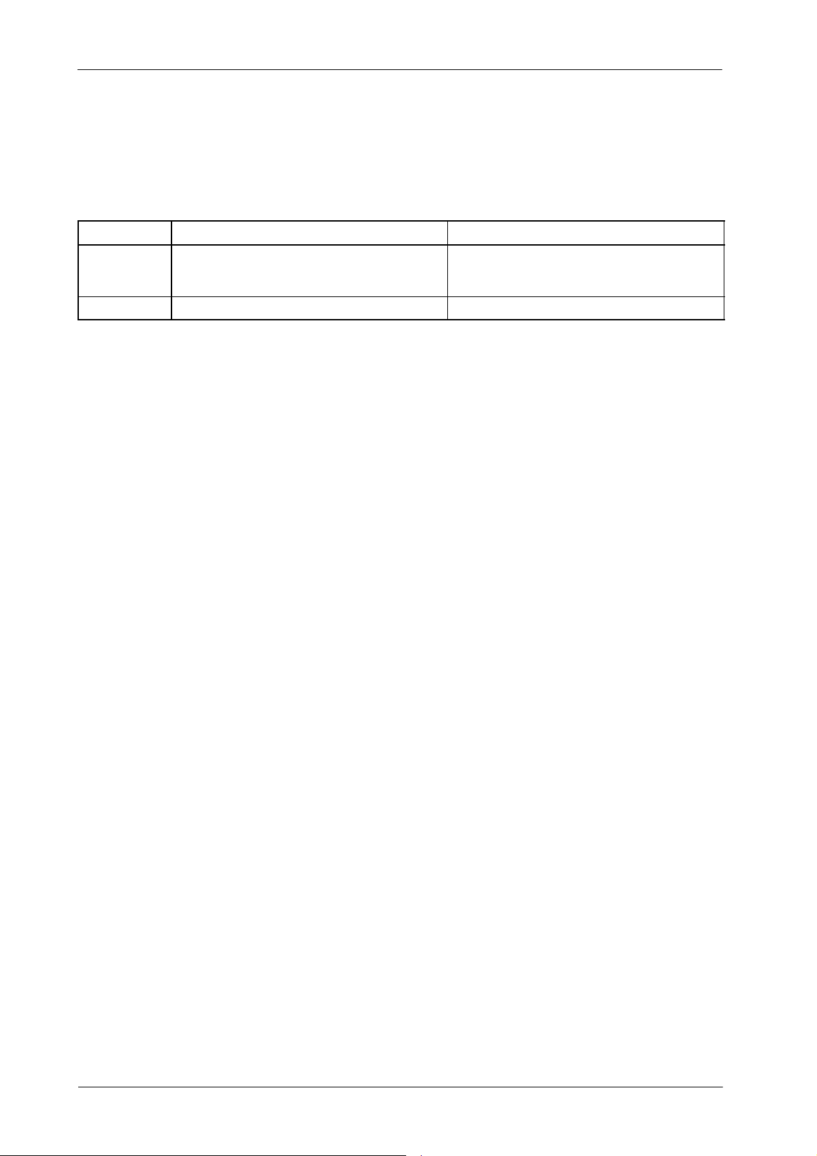
• Verify position of dip switches on the HT Controller Board during every
calibration procedure:
DIP SWITCH OPEN (OFF) CLOSED (ON)
3000SW2-2
3000SW2-4 Position during operation -- Digital mA Loop Closed Digital mA Loop Open / Filament Current Constant
Position during operation -- Enables Filament and
Rotor Interlocks
Note .
Only for Generators with Low Speed Starter (LF-RAC) (it does not
Disables Filament and Rotor Interlocks
(this turns off the filament so no radiation will
be produced during the exposure).
apply to Generators with High Speed Starter - LV-DRAC):
-- When the Digital mA Loop is open (dip switch 3000SW2-4 in
“On”), the rotor runs for two minutes after releasing the handswitch
button from “Preparation” position. After this time the rotor will
brake (unless DC Brake is removed).
-- When the Digital mA Loop is closed (dip switch 3000SW2-4 in
“Off”), the rotor will brake after releasing the handswitch button
from “Preparation” position (unless DC Brake is removed).
• Be sure that X-ray Tubes configured in E02 and E18 Memory Locations
correspond to X-ray Tubes installed (refer to Configuration document).
2.1 FILAMENT STAND-BY CURRENT
Note .
Note .
4
For RAD Only Generators, the Filament Stand-by value is
auto-calibrated by the Generator and automatically stored into the
respective Memory Locations (E01 and E17). Filament Stand -by
values are not field changeable.
For RAD and Fluoro Generators, E17 Memory Location (”Fluoro
Filament Setting”) sets maximum patient Entrance Skin Exposure
Dose Rate. (Refer to Section 2.7 “Fluoro Calibration”).
CA-1004R4
Page 9
2.2 EXPOSURE TIME ADJUSTMENT
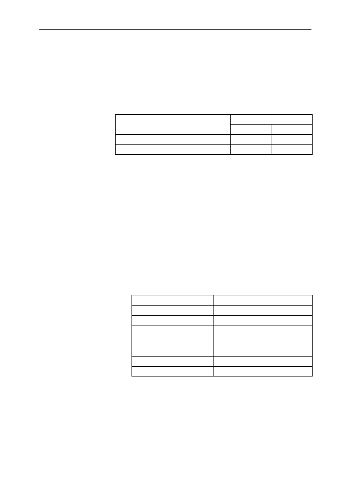
The values stored in these Extended Memory Locations only affect to Exposure
Times for techniques below 20 ms. The Memory Locations which affect short
exposure times are:
HF Series Generators
Calibration
FUNCTION
EXPOSURE TIME ADJUSTMENT - DELAY E13 E29
EXPOSURE TIME ADJUSTMENT - Ceq kV E15 E31
MEMORY LOCATION
TUBE-1 TUBE-2
The Generator has been optimized at the factory to produce correct exposures
at the lower times (<20 ms.) Therefore do not change the value factory set for
E13 and E29 Memory Locations and only adjust the value for E15 and E31
Memory Location according to the HV Cables length.
The Exposure Time adjustment is calibrated by performing the following steps:
1. Enter calibration mode.
2. Select the E13 (or E29) Memory Location. Value in this Memory Location
adjusts the time delay of the exposure. It is factory set for a value of 17,
18 or 19 (default v alue is “18”). Only read this value, do not change it.
3. Selectthe E15 (or E31) Memory Location. Valuein this Memory Location
is set in relation to the length in meters of one of the HV Cables
(1 ft = 0.3048 m). Verify the HV Cable length in meters and set the
following value:
CA-1004R4
HV CABLE LENGTH VALUE TO SET IN MEMORY
4m 27
6m 31
9m 38
12 m 45
14 m 49
16 m 54
For another HV Cable length value = (2.2711 x cable length) + 17.744
4. Store the new value of each Memory Location.
5. Exit from calibration mode and record the new values in the Data Book.
6. Repeat the above calibration process for the second tube (memory
locations E29 and E31).
5
Page 10

HF Series Generators
Calibration
2.3 KV LOOP
Extended Memory Location E06 contains the calibration factor for kV Loop.
Each number above or below of the indicated in the E06 memory location
increases or decreases respectively the kV gain value.
Note .
Value in E06 Memory Location is only related to the Generator
performance (it is not related to the X-ray Tube(s) or another
components installed), so value in this Memory Location is
factory adjusted. Only perform this procedure if the HT Controller
Board and/or HV Transformer have been replaced in the unit.
The kV Gain for kV Loop can be manually calibrated with a Non-Invasive kV
Meter (recommended procedure) or Auto-calibrated with HV Bleeder.
Manual Calibration of E06 Memory Location
1. With the Generator power OFF:
G Set Dip switch 3000SW2-2 on the HT Controller Board in “Off”
position (enables Filament and Rotor Interlocks).
G Set Dip switch 3000SW2-4 on the HT Controller Board in “On”
position (Digital mA Loop Open / Filament Current Constant).
G Remove the link between the banana plug connections on the HV
Transformer. Connect the mAs Meter to the banana plug
connections to measure mA or mAs.
G Place and center a Non-Invasive kVp Meter on the X-ray Tube
output at the required SID (refer to the Non-Invasive kVp Meter
documentation).
2. Enter in calibration mode.
3. Select the E06 Memory Location and read the calibration value by
pressing the “AEC Reset” push-button. Enter the value “200” and store
it by pressing the “AEC Reset” push-button.
6
CA-1004R4
Page 11

HF Series Generators
Calibration
4. Calibrate manually the Filament Current Number for 80 kV / 200 mA
combination, as indicated in the following steps (if it has not been
previously calibrated).
In calibration mode, Filament Current Numbers are shown on the kV
Display by pressing the “AEC Reset” push-button after selecting the
respective kV / mA combination. They can be changed by pressing the
“Increase” and “Decrease” (or “+1” and “ -- 1 ”) density push-buttons and
stored by pressing the “AEC Reset” push-button.
Select 80 kV, 200 mA and set value “344” on Filament Current Number.
Make an exposure. The mAs read on the mAs Meter must be the same
mAs displayed on the calibration screen with a tolerance of ±0.1 mAs
(tolerance of the parameter and mAs Meter).
If the mAs is low, increase the filament number. If the mA is high (or
“Generator Overload” Error is shown), decrease the filament number.
Press the “AEC Reset” push-button before making a new exposure.
Repeat until the mAs read is correct and the mA station is calibrated.
5. Exit from Calibration mode.
6. Select:80 kV, 200 mA, 100 ms. Make an exposure and note the kV value
at the end of the exposure.
7. If calibration of the kV Loop is correct (80 ±1 kV), record value “200”in
the Data Book.
8. If calibration of the k V Loop is not correct:
a. Enter in Calibration mode and select the E06 Memory Location.
Press the “AEC Reset” push-button to read the value stored.
b. Increase or decrease the value to increase or decrease the kV
respectively. Enter the new value and store it by pressing the “AEC
Reset” push-button.
c. Exit calibration mode and repeat the exposure (step-6.)to
determine if the new value has had the proper effect, if not repeat
step-8.
CA-1004R4
d. When it is correct, record the new value for E06 Memory Location
in the Data Book.
9. After calibration of E06 Memory Location, remove the Non-Invasive kVp
Meter.
7
Page 12

HF Series Generators
Calibration
Auto-Calibration of E06 Memory Location
1. With the Generator power OFF:
G Set Dip switch 3000SW2-2 on the HT Controller Board in “On”
position (disables Filament and Rotor Interlocks).
G Remove the HV Cables from the X-ray Tube and connect them to
the HV Bleeder, then connect a short couple of HV Cables from the
HV Bleeder to the X-ray Tube.
2. Enter in Calibration mode and select the E06 Memory Location.
EACH TIME THAT AUTO-CALIBRATION IS ACTIVATED IN
THIS MEMORY LOCATION, CALIBRATION DATA STORED IS
DELETED AND A NEW CALIBRATION FOR IT WILL BE
REQUIRED.
3. Enter in Auto-calibration mode pressing the “Power On” and
“kV Increase” push-buttons. After releasing both push-buttons, code
“222” is flashing on the Console accompanied of an alarm waiting
confirmation for entering in Auto-calibration mode.
Keep pressed the “kV increase” and “Power On” push-buttons again until
code “222” disappears on the Console to confirm Auto-calibration mode
or press only the “Power On” push-button to leave Auto-calibration mode
and return to manual calibration.
4. Make an exposure (technique parameters are pre-programmed at
100 kV, 200 mA and 32 ms and they can be shown when pressing the
“Prep” button).
5. Read the kVp measured with the HV Bleeder and enter this value on the
kV Display by pressing the “kV Increase” or “kV Decrease” buttons.
6. Exit from Auto-calibration mode pressing the “Power ON” and
“kV Decrease” push-buttons. At this moment, the Generator will
calculate and store the new value in E06 Memory Location.
Auto-calibration is deactivated and the process is finished when “E06”is
indicated on the Console again.
7. Read the new value stored in E06 Memory Location pressing the “AEC
Reset” push-button. Record this value in the Data Book.
8. Exit calibration mode.
9. After calibration of E06 Memory Location:
G Switch the Generator power OFF.
G Remove the HV Bleeder and connect the HV Cables from the
Generator directly to the X-ray Tube.
8
CA-1004R4
Page 13
2.4 DIGITAL mA LOOP CLOSED
Extended Memory Locations E03 and E05 contain the calibration factor for
Digital mA Loop Closed. Each number above or below the indicated in the
memory locations increases or decreases respectively the mA gain value.
HF Series Generators
Calibration
Note .
Values in E03 and E05 Memory Locations are only related to the
Generator performance (they are not related to the X-ray Tube(s)
installed), so values in these Memory Locations are factory
adjusted. Only perform this procedure if the HT Controller Board
and/or HV Transformer have been replaced in the unit.
The mA Gain for Digital mA Loop Closed is calibrated by performing the
following steps:
1. With the Generator power OFF, set:
G Dip switch 3000SW2-2 on the HT Controller Board in “Off” position
(enables Filament and Rotor Interlocks).
G Dip switch 3000SW2-4 on the HT Controller Board in “On” position
(Digital mA Loop Open / Filament Current Constant).
G Remove the link between the banana plug connections on the HV
Transformer. Connect the mAs Meter to the banana plug
connections to measure mA or mAs.
2. Select one available workstation (eg. “No Bucky”).
CA-1004R4
3. Calibrate E03 and E05 Memory Locations as described in the following
pages.
EACH TIME THAT AUTO-CALIBRATION IS ACTIVATED IN
ONE OF THESE MEMORY LOCATIONS, CALIBRATION DATA
STORED FOR THAT MEMORY LOCATION IS DELETED AND
A N EW CALIBRATION FOR IT WILL BE REQUIRED.
4. After calibration of E03 and E05 Memory Locations:
G Switch the Generator power OFF.
G Disconnect the mAs Meter to the banana plug connections.
G Re-install the link between the banana plug connections on the HV
Transformer.
9
Page 14

HF Series Generators
Calibration
For Low mA stations (from 10 mA to 80 mA) (E03 Memory Location):
1. Enter calibration mode and select the E03 memory location.
2. Enter Auto-calibration mode pressing the “Power On” and “kV increase”
push-buttons. After releasing both push-buttons, code “222” is flashing
on the Console accompanied of an alarm waiting confirmation for
entering in Auto-calibration mode.
Keep pressed the “kV increase” and “Power On” push-buttons again until
code “222” disappears on the Console to confirm Auto-calibration mode
or press only the “Power On” push-button to leave Auto-calibration mode
and return to manual calibration.
Auto-calibration is activated when the Console shows the value
“3.5 mAs”.
3. Perform the following steps:
a. Make an exposure (technique parameters are pre-programmed at
80 kV, 32 mA and 100 ms and they can be shown when pressing
the “Prep” push-button).
b. Read the mAs measured on the mAs Meter.
c. Read the Filament Current Number shown on the kV Display by
pressing the “Increase” and “Decrease” (or “+1” and “-- 1 ”) density
push-buttons. Since these push-buttons are also used to increase
or decrease the values one number should be added or subtracted
from the reading to obtain the correct value.
d. Increase or decrease the Filament Current Number to determine
the correction needed to obtain a value between 3.00 and 4.00
mAs in the mAs Meter after making a new exposure.
e. Repeat the above steps until a proper mAs value is obtained in the
mAs Meter.
4. Enter the mAs value read in the mAs Meter (it must be a value between
3.00 and 4.00 mAs) in the mAs Display pressing the “mAs increase”or
“mAs decrease” push-buttons.
5. Exit from Auto-calibration mode pressing the “Power On” and
“kV decrease” push-buttons. At this moment, the Generator will
calculate and store the new value in E03 memory location.
Auto-calibration is deactivated and the process is finished when “E03”is
indicated on the Console again.
10
6. Read the new value stored in E03 memory location pressing the
“AEC Reset” push-button. Record this value in the Data Book.
7. Exit calibration mode.
CA-1004R4
Page 15

HF Series Generators
Calibration
For High mA stations (from 100 mA) (E05 Memory Location):
1. Enter calibration mode and select the E05 memory location.
2. Enter Auto-calibration mode pressing the “Power On” and “kV increase”
push-buttons. After releasing both push-buttons, code “222” is flashing
on the Console accompanied of an alarm waiting confirmation for
entering in Auto-calibration mode.
Keep pressed the “kV increase” and “Power On” push-buttons again until
code “222” disappears on the Console to confirm Auto-calibration mode
or press only the “Power On” push-button to leave Auto-calibration mode
and return to manual calibration.
Auto-calibration is activated when the Console shows the value
“7.75 mAs”.
3. Perform the following steps:
a. Make an exposure (technique parameters are pre-programmed at
80 kV, 125 mA and 64 ms (
or 63 ms or 65 ms depending on Generator)
and they can be shown when pressing the “Prep” push-button).
b. Read the mAs measured on the mAs Meter.
c. Read the Filament Current Number shown on the kV Display by
pressing the “Increase” and “Decrease” (or “+1” and “-- 1 ”) density
push-buttons. Since these push-buttons are also used to increase
or decrease the values one number should be added or subtracted
from the reading to obtain the correct value.
d. Increase or decrease the Filament Current Number to determine
the correction needed to obtain a value between 7.00 and 8.50
mAs in the mAs Meter after making a new exposure.
e. Repeat the above steps until a proper mAs value is obtained in the
mAs Meter.
4. Enter the mAs value read in the mAs Meter (it must be a value between
7.00 and 8.50 mAs) in the mAs Display pressing the “mAs increase”or
“mAs decrease” push-buttons.
5. Exit from Auto-calibration mode pressing the “Power On” and
“kV decrease” push-buttons. At this moment, the Generator will
calculate and store the new value in E05 memory location.
Auto-calibration is deactivated and the process is finished when “E05”is
indicated on the Console again.
CA-1004R4
6. Read the new value stored in E05 memory location pressing the
“AEC Reset” push-button. Record this value in the Data Book.
7. Exit calibration mode.
11
Page 16

HF Series Generators
Calibration
2.5 DIGITAL mA LOOP OPEN (X-RAY TUBE CALIBRATION)
To achieve the most accurate calibration, this procedure has to be
automatically performed by the Generator (Auto-calibration). Calibration
procedure will be manually performed by the field engineer only if
Auto-calibration is not possible.
Two different methods are described in this section: Auto-calibration and
Manual Calibration.
Digital mA Loop Open is calibrated by performing the following steps:
1. With the Generator power OFF, set:
G Dip switch 3000SW2-2 on the HT Controller Board in “Off” position
(enables Filament and Rotor Interlocks).
G Dip switch 3000SW2-4 on the HT Controller Board in “On” position
(Digital mA Loop Open / Filament Current Constant).
2. Turn the Generator ON.
3. Enterin Calibration mode. Select the E17 Memory Location and store the
value “086”. Press the “AEC Reset” push-button to read the value stored.
Exit calibration mode.
4. Perform the Auto-calibration procedure as described in Section 2.5.1 for
each X-ray Tube in the system.
2.5.1 AUTO-CALIBRATION OF DIGITAL mA LOOP OPEN
Auto-calibration of the Filament Current Numbers is divided in two separated
procedures related to the mA stations configured for the Small or Large Focal
Spots.
It is recommended to start with the Small Focal Spot (first group) and continue
with the Large Focal Spot (second group).
EACH TIME THAT AUTO-CALIBRATION IS ACTIVATED IN A
mA STATION (OR IN “E01” MEMORY LOCATION), ALL THE
FILAMENT CURRENT NUMBERS OF THE SELECTED FOCAL
SPOT ARE AUTOMATICALLY SET TO “344”. SO A NEW
COMPLETE CALIBRATION OF THE FILAMENT CURRENT
NUMBERS FOR THIS FOCAL SPOT WILL BE REQUIRED.
12
CA-1004R4
Page 17
HF Series Generators
Calibration
Auto-calibration starts with the minimum available mA station for the selected
Focal Spot at 50 kV and follows with the other combinations of mA stations for
the selected Focal Spot at 80 kV, 120 kV and 40 kV.
1. Select one available workstation for the X-ray Tube selected. This
workstation has to be one of the previously configured as “Direct”.
2. Enter calibration mode and select one of the configured mA stations for
the Small Focal Spot.
3. Enter Auto-calibration mode pressing the “Power On” and “kV increase”
push-buttons. After releasing both push-buttons, code “222” is flashing
on the Console accompanied of an alarm waiting confirmation for
entering in Auto-calibration mode.
Keep pressed the “kV increase” and “Power On” push-buttons again until
code “222” disappears on the Console to confirm Auto-calibration mode
or press only the “Power On” push-button to leave Auto-calibration mode
and return to manual calibration.
Note .
Auto-calibration is activated after releasing both push-buttons. At this
moment, the Generator will check the mA stations available for the Small
Focal Spot. A “double-beep” will sound when the verification is
completed.
4. Check that the Heat Units available for the X-ray Tube are 100%
(kV Display shows “H -- --” on the Console).
BEFORE MAKING ANY EXPOSURE IN AUTO-CALIBRATION,
VERIFY THAT THE LINK BETWEEN THE BANANA PLUG
CONNECTIONS ON THE HV TRANSFORMER IS INSTALLED.
5. Keep fully pressed the Handswitch push-button or use the Exposure
Controls on the Console to perform continuous exposures.
In Auto-calibration mode, all technique parameters are factory
pre-programmed and they can not be changed.
Auto-calibration can be paused momentarily by releasing the
Handswitch push-button or the Exposure Controls. Do not
exit f rom Auto-calibration before the procedure has been
completed.
CA-1004R4
Note .
Auto-calibration can be cancelled by pressing the “Power On” and
“kV decrease” push-buttons. A double “double-beep” sound and
new values displayed on the Console indicates Auto-calibration is
deactivated.
13
Page 18

HF Series Generators
Calibration
If during Auto-calibration process, any error indication is shown
momentarily on the Console (such as “Tube Overload”, etc.), it means
that Generator can not calibrate in this moment the selected kV / mA
combination (because anode overheated, space charge, Generator
power limit, etc.). In this case, the Generator will continue with
Auto-calibration of the following available kV / mA combinations for the
selected Focal Spot. At the end of the process it will try to calibrate or
calculate the combinations previously uncalibrated.
If the Heat Units available for the X-ray Tube are less than 40%,
exposures are inhibited momentarily and code “111”will be flashed on the
Console accompanied of an alarm. The alarm will stop when the X-ray
Tubebegins to cool and recovers the Heat Units capacity, exposures can
be performed again even though code “111” is shown on the Console.
At this point, it is r ecommended to wait until the Heat Units available are
closed to the 80% of the X-ray Tube capacity without making any
exposure.
Generator tries to calibrate each kV / mA combination for ten (10)
attempts (maximum). If calibration is aborted (after ten attempts), code
“888” will be flashing on the Console until press the “Power On”
push-button. Calibration can be also aborted due to space charge during
calibration of the lowest kV at the highest mA stations for the Focal Spot
selected, so code “777” will be flashing on the Console until press the
“Power On” push-button.
IF AUTO-CALIBRATION IS ABORTED (CODE “888” OR
“777”), CONTINUE THE AUTO-CALIBRATION PROCEDURE
FOR THE OTHER FOCAL SPOT. CHECK AT THE END OF THE
AUTO-CALIBRATION PROCEDURE WHICH KV / MA
COMBINATIONS HAVE NOT BEEN AUTO-CALIBRATED FOR
EACH FOCAL SPOT (THESE COMBINATIONS HAVE THE
FILAMENT CURRENT NUMBER SET TO “344”). MANUALLY
CALIBRATE THESE KV / MA COMBINATIONS AS EXPLAIN IN
SECTION 2.5.2.
When Auto-calibration is successfully performed, code “999” will be
flashing on the Console until press the “Power On” push-button to exit
from Auto-calibration mode. A double “double-beep” sound and new
values displayed on the Console indicates Auto-calibration is
deactivated.
14
CA-1004R4
Page 19

HF Series Generators
Calibration
6. Repeat the s ame procedure for the Large Focal Spot selecting one of
the configured mA stations for the Large Focal Spot previous to enter in
Auto-calibration mode.
Before starting the exposures, it is recommended to wait until the Heat
Units available are closed to the 80% of the X-ray Tube capacity.
7. After performing both procedures (for Small and Large Focal Spots),
select in calibration mode each combination of the available mA stations
at the kV break points (40, 50, 80 and 120 kV). Press the “AEC Rese t”
push-button to read on the kV Display the new value of the Filament
Current Number stored for each combination and record the new values
in the Data Book.
Note that the highest mA station for Small Focal Spot may have numbers
larger than the lowest mA station for Large Focal Spot. This is normal.
8. Exit calibration mode.
9. Repeat the above calibration process for the second tube.
10. Turn the Generator power OFF and set Dip Switch 3000SW2-4 on the
HT Controller Board in “Off” position (Digital mA Loop Closed).
2.5.2 MANUAL CALIBRATION OF DIGITAL mA LOOP OPEN
This procedure describes the Manual calibration of all the Filament Current
Numbers. It has to be also used to calibrate the kV / mA combinations not
performed during Auto-calibration procedure because it has not been
completed. These combinations have the Filament Current Number set to
“344”, so only these combinations have to be manually calibrated as described
in this procedure.
Manual Calibration is initiated at the 80 kV break point by entering the
appropriate Filament Current Number for the proper tube current at each
selectable mA. Calibration at the other kV break points (40, 50, 80 and 120 kV)
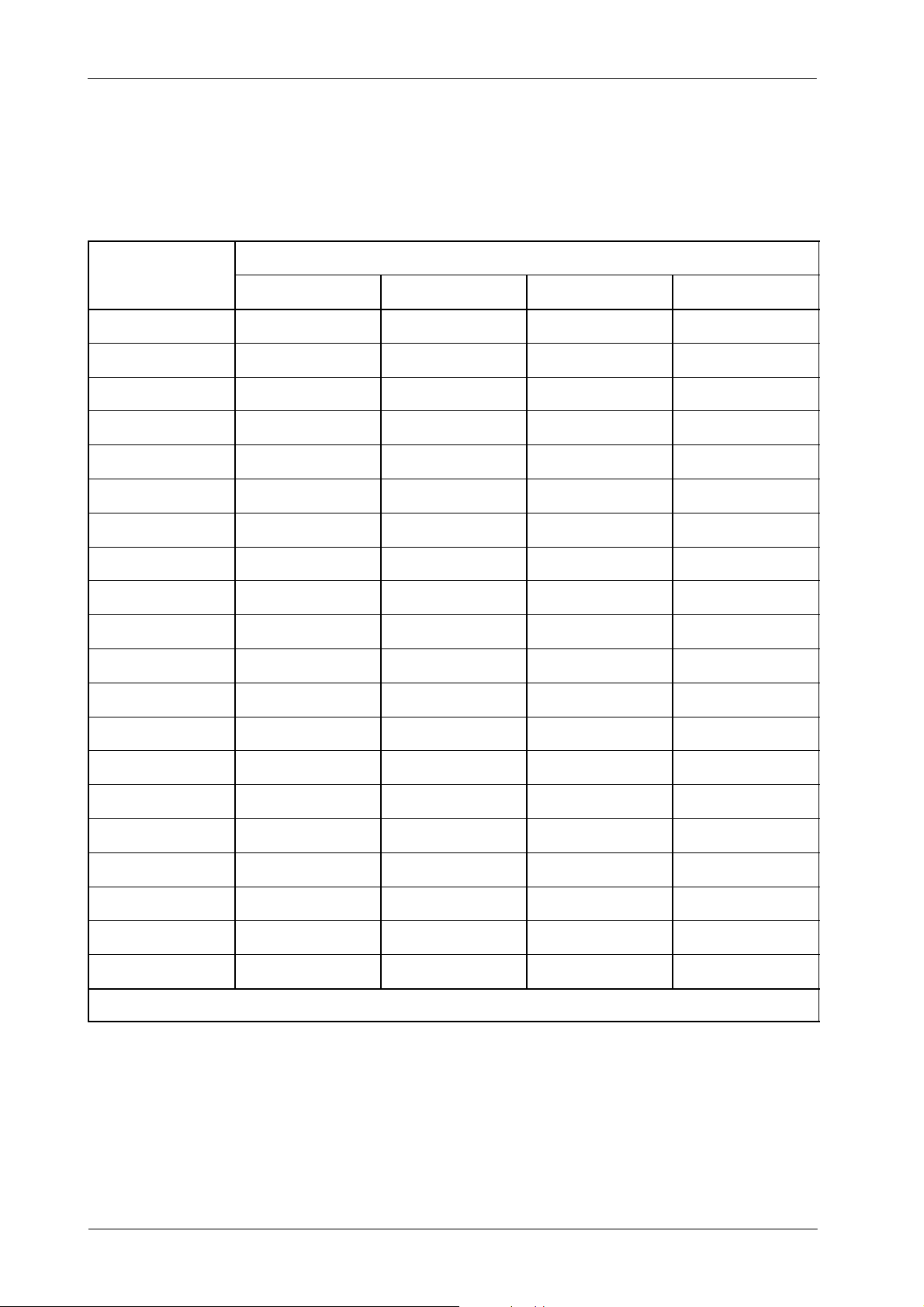
are obtained by adding or subtracting values as indicated in Table 2-1.
Although the suggested values (Table 2-1) could change depending on the
X-ray tube used, entering those values will approximate accurate calibration
without making excessive exposures.
CA-1004R4
15
Page 20
HF Series Generators
Calibration
Table 2-1
mA Calibration Numbers Change
mA STATION
40 50 80 120
FILAMENT CURRENT NUMBERS AT kV BREAK POINT
10 A1+7 A1+6 A
12.5 A2+7 A2+6 A
16 A3+7 A3+6 A
20 A4+7 A4+6 A
25 A5+7 A5+6 A
32 A6+7 A6+6 A
40 A7+7 A7+6 A
50 A8+7 A8+6 A
64 (or63or65) A9+7 A9+6 A
80 A10+7 A10+6 A
100 A11+10 A11+8 A
125 A12+10 A12+8 A
160 A13+10 A13+8 A
200 A14+10 A14+8 A
1
2
3
4
5
6
7
8
9
10
11
12
13
14
A1-- 5
A2-- 5
A3-- 5
A4-- 5
A5-- 5
A6-- 5
A7-- 5
A8-- 5
A9-- 5
A10-- 5
A11-- 7
A12-- 7
A13-- 7
A14-- 7
250 A15+10 A15+8 A
320 A16+14 A16+11 A
400 A17+14 A17+11 A
500 A18+14 A18+11 A
640 (or 630 or 650) A19+14 A19+11 A
800 A20+14 A20+11 A
15
16
17
18
19
20
A15-- 7
A16-- 9
A17-- 9
A18-- 9
A19-- 9
A20-- 9
Note.-- The mA station values depends on the Generator model. Some models do not contain all the mA stations listed above.
16
CA-1004R4
Page 21

HF Series Generators
Calibration
In calibration mode, Filament Current Numbers are shown on the kV Display by
pressing the “AEC Reset” push-button after selecting the respective kV / mA
combination. They can be changed by pressing the “Increase” and “Decrease”
(or “+1” and “-- 1 ”) density push-buttons and stored by pressing the “AEC Reset”
push-button.
The kV Display shows again the kV when the “AEC Reset” push-button is
released. Note that in calibration mode, only the mA stations and kV (at the
break points) can be selected.
Note .
If an exposure is made while displaying a Filament Current
Number, the kV of the exposure is the previously displayed kV.
1. With the Generator power OFF, set:
G Dip switch 3000SW2-2 on the HT Controller Board in “Off” position
(enables Filament and Rotor Interlocks).
G Dip switch 3000SW2-4 on the HT Controller Board in “On” position
(Digital mA Loop Open / Filament Current Constant).
G Remove the link between the banana plug connections on the HV
Transformer. Connect the mAs Meter to the banana plug
connections to measure mA or mAs.
2. Turn the Generator ON and select one available workstation for the X-ray
Tube selected. This workstation has to be one of the previously
configured as “Direct”.
3. Check that the Heat Units available for the X-ray Tube are 100%
(kV Display shows “H -- --” on the Console).
CA-1004R4
17
Page 22
HF Series Generators
Calibration
4. Enter calibration mode and according to X-ray Tube ratings or maximum
Generator power, check which kV / mA combinations in Table 2-1 are
allowed.
If error “Tube Overload” is shown on the Console after selection of a kV
/ mA combination, it means this combination is not allowed for the
selected X-ray Tube. In calibration mode, if Generator power is
exceeded by a kV / mA combination selection, error “E-16” is shown on
the Console after “Preparation”. To reset this error, press “AEC Reset ”
push-button.
Note which combinations in Table 2-1 can not be calibrated by making
exposures (combinations not allowed due to Tube rating, maximum
Generator power, space charge, etc.) and the Exposure Time assigned
to these combinations in calibration mode.
Exit calibration mode and select the mA station and Exposure Time of
each kV / mA combination not allowed. Increase or decrease the kV
value as required to determine the kV value allowed nearest to the kV
value of the combination. Note the kV value allowed in the respective cell
of Table 2-1.
Note .
5. Enter calibration mode and select 80 kV and the lowest mA station
available (first combination available). Enter a filament number of “344”
for this combination.
6. Make an exposure. The mAs read on the mAs Meter must be the mAs
displayed on the Console ±0.1mAs(tolerance of the parameter and
mAs Meter). If the mAs read is close to zero, increase the filament
number in big steps (a.e. increase values in 40). As the mAs read is close
to the mAs displayed on the Console, increase (or reduce) the filament
number in smaller steps (a.e. increase value in 30, 20, 10, ...).
If the mAs is low, increase the filament number. If the mA is high,
decrease the filament number. Press the “AEC Reset” push-button
before making a new exposure. Repeat until the mA station is calibrated.
Press the “AEC Reset” push-buttonto store the new data (filament
number) before selecting the next kV or mA stations.
Calibration data (presently in memory) may or may not be
close to your requirements. If it is not close, the potential
exists to damage the X-ray tube (i.e. too much mA). Thus, as
you start the mA calibration procedure note how close or how
far off the mA break points are. If a large adjustment (more
than 40 points) is required at the low mA stations, make
estimated adjustments to the high mA stations before
those
exposures are made.
18
CA-1004R4
Page 23

HF Series Generators
Calibration
7. Select the next mA station at 80 kV. Before making any exposure, enter
as filament number the value calibrated for the previous mA station
increased in 10.
If the mAs is low, increase the filament number. If the mA is high,
decrease the filament number. Press the “AEC Reset” push-button
before making a new exposure. Repeat until the mA station is calibrated.
8. Complete the calibration process for all mA stations at 80 kV as
described before. When select the first mA station for the Large Focal
Spot, enter as a filament number the value calibrated for the first mA
station for the Small Focal Spot. Note that the highest mA station for
Small Focal Spot may have numbers larger than the lowest mA station
for Large Focal Spot. This is normal.
Press the “AEC Reset” push-button to read on the kV Display the new
value of the Filament Current Number stored for each mA station at
80 kV. Record the new values in the Data Book.
Note .
When highest mA stations of the Generator can not be calibrated
at 80 kV due to insufficient filament current, perform the following
modification in the equipment:
Insufficient filament current:
reached the maximum number (999), replace on the Filament
Board (A3004--05) the Resistor R26 for another resistor with
1.5
Ω /
5 W, and place Jumper JP1 in position “A”. Then rename
the Filament Board as A3004--06.
ATTENTION: After doing the above modification reduce the
value of all the filament current numbers (column for 80 kV)
at the 25% and perform the calibration procedure again (from
step-4).
9. Completethe calibration process for the remaining kV / mA combinations
using Table 2-1 as a guide. It is not necessary to make exposures to do
this. Compute the value for all the kV break points of each available mA
station although the Generator power can not reach all the kV / mA
combinations. Select the corresponding kV / mA combination and enter
the computed value.
If the filament current number has
CA-1004R4
19
Page 24

HF Series Generators
Calibration
10. Check calibration at all allowed kV / mA combinations by making
exposures and correct any calibration points as needed.
Note .
If “Tube Overload” error is shown directly on the Console after
selection of an allowed combination (refer to step-4.), wait until the
X-ray tube anode cools down to permit the calibration of the mA
station.
11. Recalculate the values of the non-allowed combinations in accordance
to the new values obtained by the previous exposures. (Refer to
Table 2-1).
12. Exit calibration mode.
13. Select the mA station, Exposure Time and kV value noted for each
kV / mA combination not allowed (refer to step-4.). Check calibration at
these kV / mA combinations by making exposures. If needed, enter in
calibration mode and correct the Filament Current Number of the
respective kV / mA combination not allowed.
14. Incalibration mode, select each combination of the available mA stations
at the kV break points (40, 50, 80 and 120 kV). Press the “AEC Rese t”
push-button to read on the kV Display the new value of the Filament
Current Number stored for each combination. Record the new values in
the Data Book.
Note that the highest mA station for Small Focal Spot may have numbers
larger than the lowest mA station for Large Focal Spot. This is normal.
15. Exit calibration mode.
16. Repeat the above calibration process for the second tube.
17. After calibration of Filament Current Numbers:
G Switch the Generator power OFF.
G Disconnect the mAs Meter to the banana plug connections.
G Re-install the link between the banana plug connections on the HV
Transformer.
G Set Dip Switch 3000SW2-4 on the HT Controller Board in
“Off” position (Digital mA Loop Closed).
20
CA-1004R4
Page 25

2.6 AEC CALIBRATION
This section describes the adjustments needed to calibrate the AEC according
to the customer input. Therefore, AEC exposures will be made during the
calibration process in order to insure AEC functionality.
The Optical Density is controlled by the values stored in the respective memory
locations. These values are influenced by film speed, screen speed, dark room
procedures and customer requirements.
Use a homogeneous Phantom with enough density to produce an exposure of
100 ms, the AEC will be calibrated to produce a density of 1.0 (or the customer
preference Optical Density) at 70 kV, and then AEC tracking will be adjusted to
produce the same density at 55 kV, 90 kV and 110 kV.
HF Series Generators
Calibration
Note .
Note .
For AEC calibration, use the same Film and Cassettes used by the
customer. AEC calibration must be performed
using the Medium
Film/Screen speed combination. The Medium Film/Screen speed
has to be double of the Slow and half of the Fast (a.e. 200--Slow,
400--Medium, 800--Fast).
When using CR (Computer Radiography) or DR (Digital
Radiography) instead of measuring Optical Density:
-- measure the Image Gray level by using the needed software
tools inside each application (refer CR or DR documentation).
-- or measure the Dose level:
-- For CR, placing the Dosimeter as close as possible to the
Cassette and centered with the Central Area of the Ion Chamber.
-- For DR, placing the Dosimeter as close as possible to the
Panel, centered with the Central Area of the Ion Chamber and with
the Grid removed.
The following table indicates the Memory Locations related to AEC Calibration.
FUNCTION MEMORY LOCATION
AEC-1 CALIBRATION E04
AEC-1 TRACKING E08
AEC-2 CALIBRATION E09
AEC-2 TRACKING E10
AEC-3 CALIBRATION E20
AEC-4 CALIBRATION / PHOTOMULTIPLIER AEC CALIBRATION E23
AEC-3 and AEC-4 TRACKING (equal value for both) E24
AEC DENSITY SCALE E12
CA-1004R4
21
Page 26
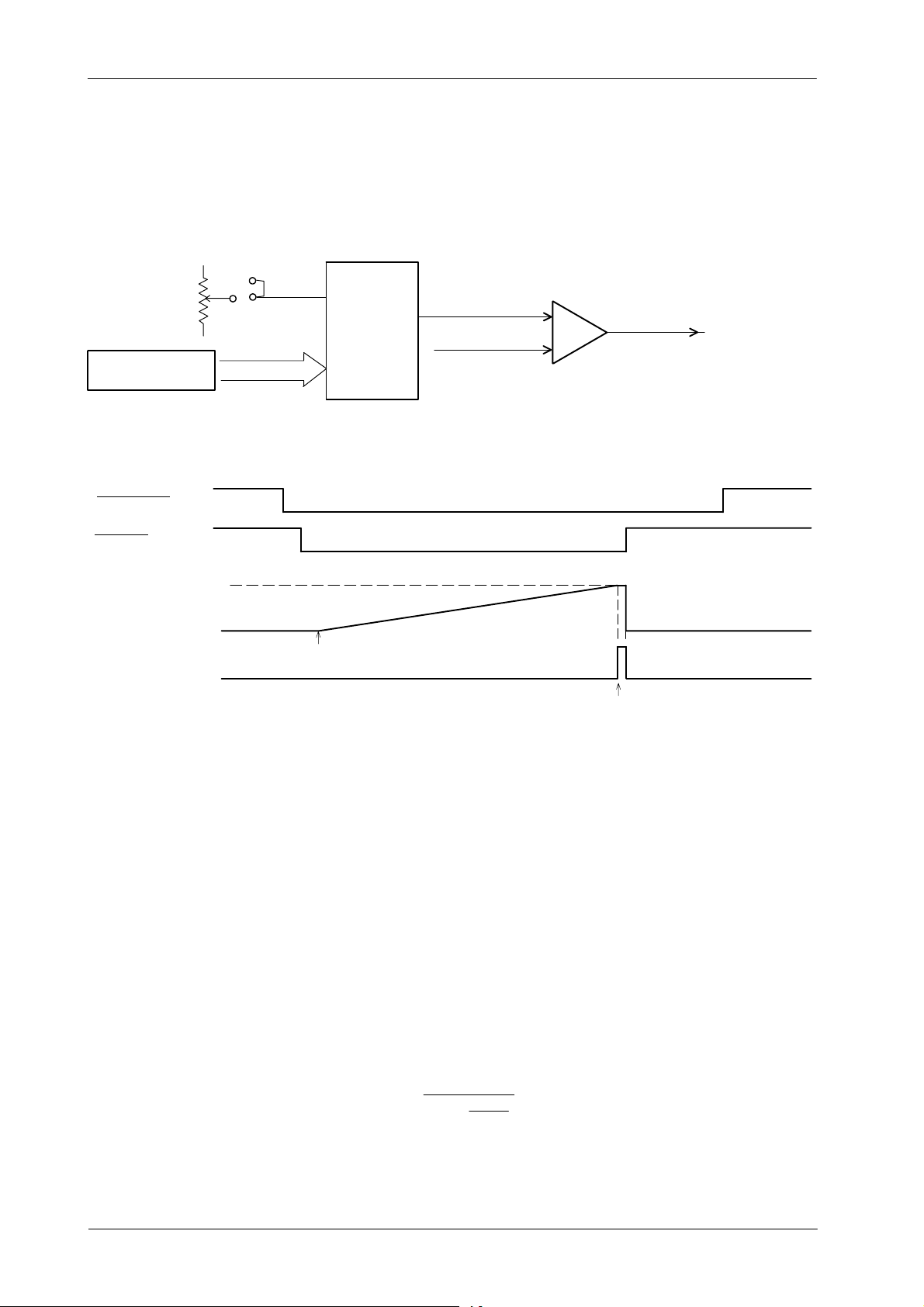
HF Series Generators
(
f1)
Calibration
Illustration 2-1
Automatic Exposure Control
Jumper
Adjustment
(Potentiomer)
ATP Console CPU
Microprocessor
EXP ORDER
Data Bus
Vref
DAC
V out
COMPARATOR
Reference
Ramp
(from Ion Chamber)
AEC STOP
to cut the exposure
STRT DR
DAC Vout (Reference)
(calibration data setting)
Ion Chamber Output
EXP Start
AEC STOP
(AEC CONTROL PCB)
2.6.1 PREVIOUS CHECKS
Make sure the automatic processor works correctly, and the concentration and
temperature of the solutions comply with manufacturer specifications.
Obtain a sensitometric curve to determine gamma (γ) of the film and the solution
quality. The procedure normally requires a sensitometer,but if it is not available
proceed as follows:
1. Make two exposures using the same kV and Film/Screen combination
AEC Function Waveform
EXP Stop
(medium is recommended) but with different mAs settings, mAs(f1) and
mAs(f2).
2. Develop and measure the Density (d) of each, d(f1) and d(f2).
3. Determine gamma (γ) by the formula:
d(f2) − d(f1)
γ =
log
10
mAs(f2)
mAs
Gamma (γ) must be between 2 and 3, if not change or renew solutions.
22
CA-1004R4
Page 27

2.6.2 BALANCE ADJUSTMENT FOR THREE FIELD DETECTORS
HF Series Generators
Calibration
Note .
Some Ion Chambers does not provide balance potentiometers for
Three Field Detectors. Continue calibration process in Section
2.6.3 “Optical Density Adjustment”.
1. Set the Master Gain potentiometer of the Ion Chambers to mid range
(refer to Ion Chamber documentation).
2. Set the following jumper on the AEC Control Board in position A: JP3 for
Board A3012--x1/x2/x5 or JP2 for Board A3012--x6/x7/x9.
3. Set SID at the Focal Distance of the Grid installed in the Table Bucky
(usually 100 cm) or in the Vertical Bucky Stand (usually 150 cm).
4. Collimate the X-ray beam so that it completely covers all three fields but
does not extend beyond limits of the phantom.
5. Place Copper plates (or equivalent homogeneous phantom) in the
Collimator Filter Holder: 1.5 mm for SID of 100 cm, 1 mm for SID 150 cm.
(1 mm Copper
6. Enter in calibration mode and verify that AEC Calibration number in E04,
E09, E20 and E23 Memory Locations is 70. The range for AEC
calibration numbers are from 20 to 120. Then exit from calibration mode.
≃
10 cm Plexiglass or Water).
7. Select on the Console:
G A Workstation configured for the Ion Chamber to be calibrated.
G RAD: 70 kV, 200 mA Large Focus (or the first mA station for Large
Focus if 200 mA station is set for Small Focus) and 1 second
back-up time.
G AEC: “Central Area”,“Density 0” and “Medium Film/Screen”.
8. Make an exposure without film in the cassette and note the Exposure
Time displayed on the Console, it should be approximately 100 ms. If
necessary, change the Copper thickness or mA station and make the
exposure again. (Last exposure parameters are displayed by pressing
the “AEC Reset” button of the Console.)
9. Deselect “Center Area” and select “Left Area”. Make an exposure
without film in the cassette and record the Exposure Time. If this time is
not equal to the “Center Area”time(± 7%), check that the Ion Chamber
is parallel to the X-ray Tube and make an exposure again. If it is parallel,
adjust “Left Area” balance potentiometer to increase or decrease
Exposure Time. Repeat this process until both Exposure Times for
“Center Area” and “Left Area” are equal.
CA-1004R4
23
Page 28
HF Series Generators
Calibration
10. Deselect “Left Area” and select “Right Area”. Make an exposure without
film in the cassette and record the Exposure Time. If this time is not equal
to the “Center Area”time(± 7%), adjust “Right Area” balance
potentiometer to increase or decrease Exposure Time. Repeat process
until both Exposure Times for “Center Area” and “Right Area” are equal.
11. Check that the three scan Areas have equal Exposure Time (± 7%):
G “Center Area”with“Left Area”, “Center Area”with“Right Area”,
and “Left Area”with“Right Area”.
G All three Areas.
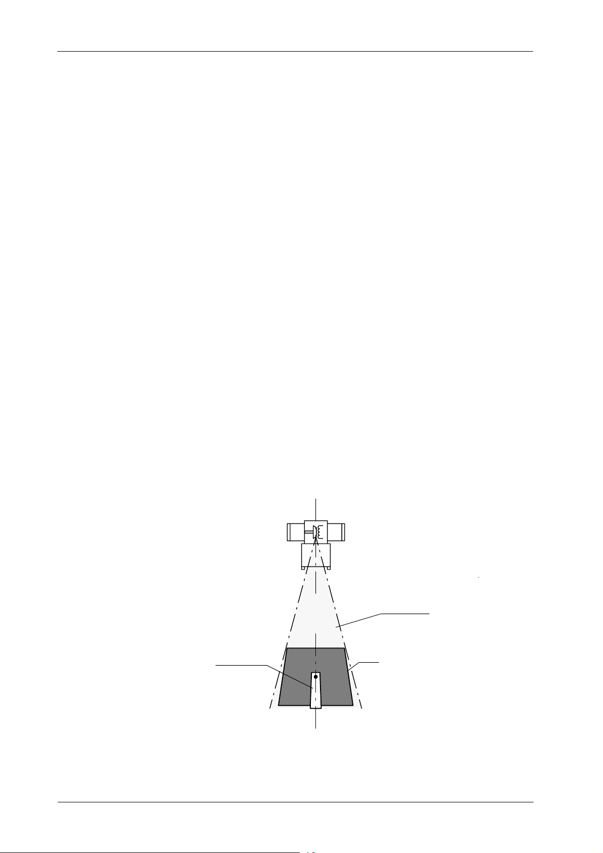
2.6.3 OPTICAL DENSITY ADJUSTMENT
Note .
The Film Optical Density must be measured always on the same
point for all the X-ray Films developed during this procedure.
The recommended point is on the central axis of the Film with
relation of the Anode and Cathode and as close as possible to
center of the Film.
Illustration 2-2
How to measure the Film Optical Density
AK
USEFUL BEAM
24
DENSITOMETER
FILM
R
CA-1004R4
Page 29
HF Series Generators
Calibration
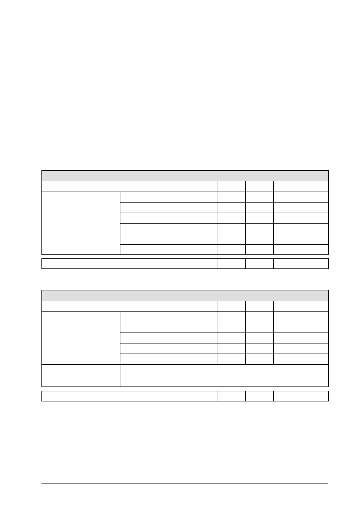
ION CHAMBERS WITH DETECTOR GAIN SWITCHES
OR WITH POTENTIOMETER
1. Set the Detector Gain switches (or gain potentiometer) of the Ion
Chamber to mid range (refer to Ion Chamber documentation). (If the Ion
Chamber is provided with the Generator, this adjustment is Factory set.)
The following tables indicate the switch position for the “Vacutec”Ion
Chamber ( Factory set).
VACUTEC ION CHAMBER -- BAK 70 151 with Amplifier 70 901
SWITCH POSITION SW1 SW2 SW3 SW4
0.1 V / µGy (10 V≃ 100 µGy)
GAIN
OUTPUT SIGNAL
NORMAL FACTORY SELECTION: 1 V / µGy (10 V≃10 µGy) - Positive
VACUTEC DIGITAL ION CHAMBER -- BAK 70 151 with Amplifier 70 902
SWITCH POSITION SW1 SW2 SW3 SW4
GAIN
OUTPUT SIGNAL
0.5 V / µGy (10 V≃ 20 µGy)
1V/µGy (10 V≃ 10 µGy)
2V/µGy (10 V≃ 5 µGy)
Positive ON
Negative OFF
0.1 V / µGy (10 V≃ 100 µGy)
0.5 V / µGy (10 V≃ 20 µGy)
1V/µGy (10 V≃ 10 µGy)
2V/µGy (10 V≃ 5 µGy)
4V/µGy (10 V≃ 2.5 µGy)
Positive or Negative polarity of the ramp signal is selected with a switch at the Ramp Module.
The Ramp Module is a 9-pin Sub-D connector plugged to the Ion Chamber cable.
Positive polarity of the ramp signal is factory set.
OFF OFF OFF
ON OFF OFF
OFF ON OFF
OFF OFF ON
OFF ON OFF ON
OFF OFF OFF OFF
OFF OFF OFF ON
OFF OFF ON OFF
OFF ON OFF OFF
ON OFF OFF OFF
NORMAL FACTORY SELECTION: 1 V / µGy (10 V≃10 µGy) - Positive
CA-1004R4
OFF OFF ON OFF
25
Page 30

HF Series Generators
Calibration
2. Set the following jumper on the AEC Control Board in position A: JP3 for
Board A3012--x1/x2/x5 or JP2 for Board A3012--x6/x7/x9.
3. Set SID at the Focal Distance of the Grid installed in the Table Bucky
(usually 100 cm) or in the Vertical Bucky Stand (usually 150 cm).
4. Collimate the X-ray beam so that it completely covers all three fields but
does not extend beyond limits of the phantom.
5. Place Copper plates (or equivalent homogeneous phantom) in the
Collimator Filter Holder: 1.5 mm for SID of 100 cm, 1 mm for SID 150 cm.
(1 mm Copper
≃
10 cm Plexiglass or Water).
6. Enter in calibration mode and verify that AEC Calibration number in E04,
E09, E20 and E23 Memory Locations is 70. The useful range for AEC
calibration numbers is from 20 to 120. Then exit from calibration mode.
7. Select on the Console:
G A Workstation configured for the Ion Chamber to be calibrated.
G RAD: 70 kV, 200 mA Large Focus (or the first mA station for Large
Focus if 200 mA station is set for Small Focus) and 1 second
back-up time.
G AEC: “Central Area”,“Density 0” and “Medium Film/Screen”.
8. Make an exposure without film in the cassette and note the Exposure
Time displayed on the Console, it should be approximately 100 ms. If
necessary, change the Copper thickness (or if needed change the mA
station) and make the exposure again. (Last exposure parameters are
displayed by pressing the “AEC Reset” button of the Console.)
9. Insert a cassette with the Medium Film/Screen combination used by the
customer. Make an exposure, develop the film and check the Optical
Density, it should be 1.0 (or the customer preference O. Density).
26
CA-1004R4
Page 31

10. To change the density:
HF Series Generators
Calibration
G For Ion Chamber with Gain switches
:
-- If the Optical Density obtained is 33% above of the desired
density, increase the gain with the switches. Repeat step-9.
-- If the Optical Density obtained is 33% below of the desired
density, decrease the gain with the switches. Repeat step-9.
-- If the Optical Density obtained is in between 33% of the desired
density, change the AEC calibration number. Enter in calibration
mode, set the new AEC calibration number for the respecetive
Memory Location (E04, E09, E20 or E23). The Optical Density
increases / decreases when the calibration number is increased
/ decreased. Then exit calibration mode. Repeat step-9.
G For Ion Chamber with Master Gain potentiometer
potentiometer until the desired density is obtained by repeating
step-9. If the adjustment is not achieved with the Master Gain
potentiometer, change the AEC calibration number. Enter in
calibration mode, set the new AEC calibration number for the
respecetive Memory Location (E04, E09, E20 or E23). The Optical
Density increases / decreases when the c alibration number is
increased / decreased. Then exit calibration mode. Repeat step-9.
, adjust this
Note .
The AEC accuracy is better in all the useful range as the AEC
calibration number is closer to 70.
11. Repeat the above steps for all the Ion Chambers installed with the
Generator.
12. Record these values in the Data Book.
CA-1004R4
27
Page 32

HF Series Generators
Calibration
ION CHAMBERS WITHOUT DETECTOR GAIN SWITCHES
OR WITHOUT POTENTIOMETER
1. Set the following jumper on the AEC Control Board in position B: JP3 for
Board A3012--x1/x2/x5 or JP2 for Board A3012--x6/x7/x9.
2. Set to mid range, the following potentiometer on the AEC Control Board:
R10 for Board A3012--x1/x2/x5 or R22 for Board A3012--x6/x7/x9.
Note .
The density adjustment of ALL the Ion Chambers in the system are
affected by this potentiometer.
3. Set SID at the Focal Distance of the Grid installed in the Table Bucky
(usually 100 cm) or in the Vertical Bucky Stand (usually 150 cm).
4. Collimate the X-ray beam so that it completely covers all three fields but
does not extend beyond limits of the phantom.
5. Place Copper plates (or equivalent homogeneous phantom) in the
Collimator Filter Holder: 1.5 mm for SID of 100 cm, 1 mm for SID 150 cm.
(1 mm Copper
6. Enter in calibration mode and verify that AEC Calibration number in E04,
E09, E20 and E23 Memory Locations is 70. The useful range for AEC
calibration numbers is from 20 to 120. Then exit from calibration mode.
7. Select on the Console:
G A Workstation configured for the Ion Chamber to be calibrated.
G RAD: 70 kV, 200 mA Large Focus (or the first mA station for Large
Focus if 200 mA station is set for Small Focus) and 1 second
back-up time.
≃
10 cm Plexiglass or Water).
28
G AEC: “Central Area”,“Density 0” and “Medium Film/Screen”.
8. Make an exposure without film in the cassette and note the Exposure
Time displayed on the Console, it should be approximately 100 ms. If
necessary for that, change the Copper thickness (or if needed change
the mA station) and make the exposure again. (Last exposure
parameters are displayed by pressing the “AEC Reset” button of the
Console.) Take note of the final Copper thickness and mA station
selected.
9. Repeat the above steps for each Ion Chamber.
CA-1004R4
Page 33

HF Series Generators
Calibration
10. Insert a cassette with the Medium Film/Screen combination used by the
customer. Make an exposure with each Ion Chamber (use the final
Copper thickness and the selected mA station noted before), develop the
film and take note of the Optical Density measured for each Ion Chamber.
11. Take the maximum and minimum value of the O. Densities measured
before, sum them and divide the result by two. Subtract this value from
density 1.0 (or the customer preference O. Density) to obtain the O.
Density difference.
O.D. difference = O.D. customer preference --
O.D. max + O.D. min
2
Calculate the new O. Density b y adding the O. D. difference (with its sign
+ or --)to the value of the O. Density measured for the Ion Chamber closer
to 1.0 (or the customer preference O. Density).
new O.D. = O.D. mesured + (O.D. difference)
For this Ion Chamber, adjust the potentiometer (turning it clockwise will
decrease the O. Density) R10 for Board A3012--x1/x2/x5 or R22 for
Board A3012--x6/x7/x9 (at least one turn). Make another exposure,
develop the film and check the Optical Density. Repeat this action
(adjusting the potentiometer and making exposures) until the new
Optical Density (calculated before) for this Ion Chamber is obtained.
12. The Optical Density for each Ion Chamber has to be adjusted to 1.0 (or
the customer preference O. Density).
Enter in calibration mode, select the AEC calibration number for the
respective Memory Location (E04, E09, E20 or E23). Change the AEC
calibration number: the Optical Density increases / decreases when the
calibration number is increased / decreased. Then exit calibration mode.
CA-1004R4
Note .
Make another exposure, develop the film and check the Optical Density.
Repeat this action (changing the respective Memory Location and
making exposures) until the desired Optical Density is obtained.
The AEC accuracy is better in all the useful range as the AEC
calibration number is closer to 70.
13. Repeat step-12. until the desired Optical Density for each Ion Chamber
is obtained.
14. Record all the values for the Memory Locations in the Data Book.
29
Page 34

HF Series Generators
Calibration
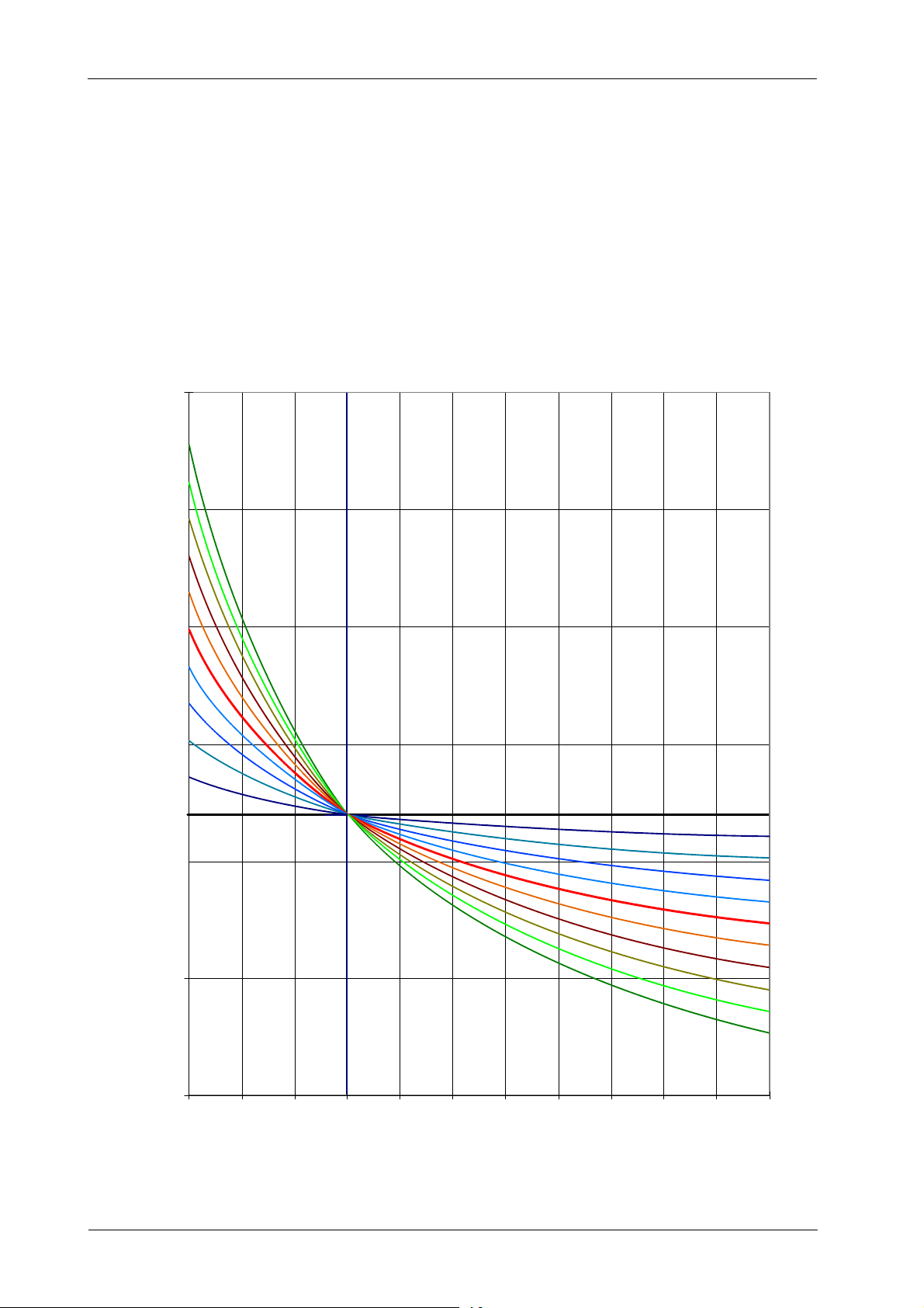
2.6.4 kV COMPENSATION
To maintain constant AEC Optical Density regardless of the kV at which a film
is exposed, the Generator provides kV compensation. (Referto Illustration 2-3)
Perform the following steps to determine whether or not AEC Tracking of Optical
Density must be adjusted.
1. Enter in calibration mode and verify that AEC Tracking number in E08,
E10 and E24 Memory Locations is “0”. Then exit from calibration mode
and Service mode.
2. Select on the Console:
G A Workstation configured for the Ion Chamber to be calibrated.
G RAD: 55 kV, 200 mA Large Focus (or the first mA station for Large
Focus if 200 mA station is set for Small Focus) and 1 second
back-up time.
G AEC: “Central Area”,“Density 0” and “Medium Film/Screen”.
3. Make an exposure without film in the cassette and check that the
Exposure Time is lower than 1 second. If necessary for that, change the
Copper thickness (or if needed change the mA station) and make the
exposure again. Take note of the final Copper thickness and mA station
selected for 55 kV.
4. Select 90 kV. Make an exposure without film in the cassette and check
that the Exposure Time is higher than 20 ms. If necessary for that, change
the Copper thickness (or if needed change the mA station) and make the
exposure again. Take note of the final Copper thickness and mA station
selected for 90 kV.
5. Select 110 kV. Make an exposure without film in the cassette and check
that the Exposure Time is higher than 20 ms. If necessary for that, change
the Copper thickness (or if needed change the mA station) and make the
exposure again. Take note of the final Copper thickness and mA station
selected for 110 kV.
6. Insert a cassette with the Medium Film/Screen combination used by the
customer. Make an exposure at 55 kV and 90 kV (use the final Copper
thickness and the selected mA station noted before for each kV),develop
the film and measure the Optical Density obtained with those exposures.
Check that the film variation range is the same ±0.2 of the Optical
Density (±20% of Image Gray Level / Dose Level with CR or DR)
obtained before at 70 kV (Density Gain Adjustment -- Section 2.6.3).
30
CA-1004R4
Page 35
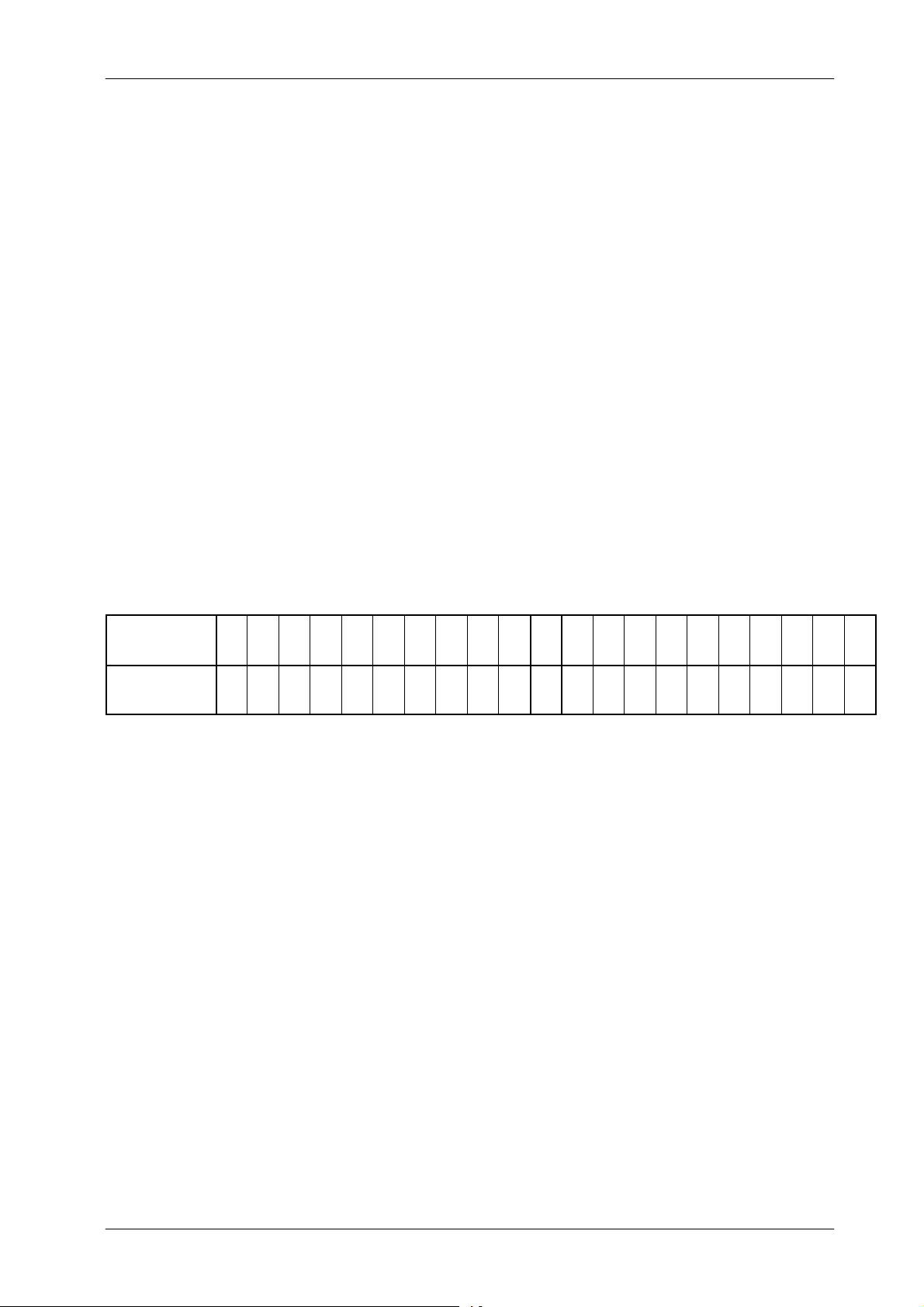
HF Series Generators
Calibration
7. If the variation value is not ±0.2 of the Optical Density (±20% of Image
Gray Level / Dose Level with CR or DR) calculate the new value for the
AEC Tracking number in each Memory Location in the following manner:
G If the Optical Density at 55 k V has to be decreased and the Optical
Density above 70 kV has to be increased then increase the
Tracking value in one.
G If the Optical Density at 55 kV has to be increased and the Optical
Density above 70 kV has to be decreased then decrease the
Tracking value in one.
Note .
AEC-kV
TRACKING
CURVE
VAL UE T O E NTER
IN THE MEMORY
LOCATION
A tracking value of 10 will have no effect on AEC density (used in
solid state detectors).
a. Enter in calibration mode and select the respective Memory
Location (E08, E10 or E24).
b. Values for AEC Tracking range is from --10 to +10. Determine the
correct value for the needed AEC Tracking change.
+10 +9 +8 +7 +6 +5 +4 +3 +2 +1
10 9 8 7 6 5 4 3 2 1
c. Enter the new value and store it by pressing the “AEC Reset”
push-button. Exit calibration mode and repeat this process from
step-6. until the desired density compensation is obtained.
8. Insert a cassette with the Medium Film/Screen combination used by the
customer. Make an exposure at 110 kV (use the final Copper thickness
and the selected mA station noted before for 110 kV), develop the film
and measure the Optical Density obtained with those exposures. Check
that the film variation range is the same ±0.2 of the Optical Density (or
±20% of Image Gray Level / Dose Level with CR or DR) obtained before
at 70 kV (Density Gain Adjustment -- Section 2.6.3). If the variation value
is not ±0.2 repeat step-7.
-- 1 -- 2 -- 3 -- 4 -- 5 -- 6 -- 7 -- 8 -- 9 -- 1 0
0
255 254 253 252 251 250 249 248 247 246
0
CA-1004R4
Note .
Calibration of AEC Tracking at 110 kV modifies the adjustment
done at 55 kV and 90 kV. Repeat exposures of step-6. and check
that they are correct.
In case that the AEC Tracking at 110 kV places the adjustment at
55 kV and 90 kV out of range, choose the AEC Tracking value
more convenient for the application.
31
Page 36
HF Series Generators
Calibration
Illustration 2-3
AEC kV Tracking Curve
250
200
9. Record all the values for the Memory Locations in the Data Book.
10. Repeat the above steps for all the Ion Chambers installed with the
Generator.
11. Record all the values for the Memory Locations in the Data Book.
150
100
70
50
DAC OUTPUT in byte (8 Bit) (U3-2 of AEC Control Board)
10
8
6
4
2
0
-- 2
0
-- 4
-- 6
-- 8
-- 1 0
32
-- 5 0
40 50 60 9070 80 100 110 120 130 140 150
kV
CA-1004R4
Page 37

HF Series Generators
2.6.5 PHOTOMULTIPLIER RAD--AEC (DIGITAL RAD) ADJUSTMENT (OPTIONAL)
The Photomultiplier RAD--AEC (Digital RAD) adjustment can b e performed in
two ways: one is the value stored in E23 Memory Location and the other is the
high voltage applied to the Photomultiplier Tube.
The recommended procedure for this adjustment is to store a constant value
in E23 Memory Location and adjust the high voltage applied to the
Photomultiplier Tube.
Calibration
Note .
Value in E23 Memory Location is a common data used for
Photomultiplier AEC Calibration or used for the Fourth Ion
Chamber Calibration (AEC-4).
Perform the following procedure:
1. Enter in calibration mode. Select E23 Memory Location and set a value
of “127”. Then exit from calibration mode and Service mode.
2. Set up a Dosimeter as close as possible to the Image Intensifier
Radiation Input to measure the Entrance Image Intensifier Exposure
Dose Rate. Position the Probe at the center of the primary beam with the
entire active volume within the primary beam. Select the Field of View
for the Image Intensifier to have 9” FOV.
Place the Tube-Collimator Assembly at the normal SID (1 meter).
Collimate the X-ray beam so it completely covers the Image Intensifier
field but does not extend beyond limits of the phantom.
CA-1004R4
3. Place 2 mm of Copper (or equivalent homogeneous phantom) in the
Collimator Filter Holder. (1 mm Copper
4. Select on the Console:
G RAD: 70 kV, 200 mA Large Focus (or the first mA station for Large
Focus if 200 mA station is set for Small Focus) and 1 second
back-up time.
G AEC: “Central Area”,“Density 0” and “Medium Film/Screen”.
≃
10 cm Plexiglass or Water).
33
Page 38

HF Series Generators
Calibration
5. According to software installed on the ATP Console CPU Board:
G for software V4Rx or V5Rx: Before “Prep” is activated on the
Console, select the Photomultiplier (--PT SEL / --SFC signal =
GND on TS3-7 Generator Cabinet) and select Digital RAD (--DSI
SEL signal = GND on J13--5 ATP Console CPU Board). Hold
“Prep” and adjust the high voltage applied to the Photomultiplier
Tube with the following potentiometer on the AEC Control Board:
R12 for Board A3012--x1/x2/x5 or R23 for Board A3012--x6/x7/x9;
until measure --400 VDC between TS1--39 and TS1--42 (GND) in
the Generator Cabinet.
G for software V6Rx or greater: Select a Digital Workstation
configured for Device = DSI. Activate “Digital Prep”(--DIGITAL
PREP signal = GND on TS3-7 Generator Cabinet). Hold “Digital
Prep” and adjust the high voltage applied to the Photomultiplier
Tube with the following potentiometer on the AEC Control Board:
R12 for Board A3012--x1/x2/x5 or R23 for Board A3012--x6/x7/x9;
until measure --400 VDC between TS1--39 and TS1--42 (GND) in
the Generator Cabinet.
Note .
6. The Dose is affected in the following manner:
G Increases when the high voltage applied to the Photomultiplier
Tube is decreased. (Example: if 100
--400 VDC, 200
voltage to --300 VDC).
G Decreases when the high voltage applied to the Photomultiplier
Tubeis increased. (Example: if 100
VDC, 50
--450 VDC).
7. Make an exposure and adjust the following potentiometer on the AEC
Control Board: R12 for Board A3012--x1/x2/x5 or R23 on for Board
A3012--x6/x7/x9; until getting a typical Dose around 100 µR per frame
(at 9” FOV)(for more information refer to the Image System
documentation).
If the photo tube voltage required is too low, decrease the AEC
calibration number in the E23 Memory Location and repeat the
process.
µ
µ
R Dose may be obtained decreasing the high
R Dose may be obtained increasing the high voltage to
µ
R Dose is obtained with
µ
R Dose is obtained with --400
34
8. Record the E23 Memory Location in the Data Book.
CA-1004R4
Page 39
2.6.6 AEC OPTICAL DENSITY SCALE
V
A
E12
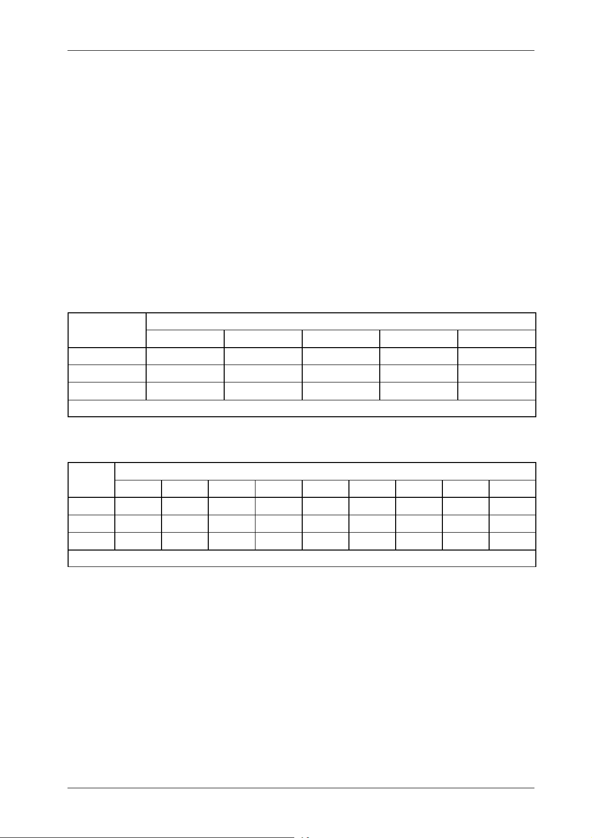
AEC is calibrated with “Density 0” selected (Normal Optical Density). The
Optical Density can be increased or decreased in several steps.
The variation percentage of the density scale is factory set at 25%. This
variation can be set according to the customer preferences by changing the
value stored in E12 Memory Location. This value applies to both tubes.
Depending on the Console model, the range of the scale is “from --2 to +2” or
“from --4 to +4” (optional ).
The following tables show some examples for the variation percentage of the
density scale with reference to the value stored in E12 Memory Location.
HF Series Generators
Calibration
E12
LUE
5 N x 0.90 N x 0.95 N N x 1.05 N x 1.10
10 N x 0.80 N x 0.90 N N x 1.10 N x 1.20
25 N x 0.50 N x 0.75 N N x 1.25 N x 1.50
NOTE: If the value stored in E12 Memory Location is 0, 25 or 255, the variation percentage is 25%.
E12
VAL UE
5 N x 0.82 N x 0.86 N x 0.91 N x 0.95 N N x 1.05 N x 1.10 N x 1.16 N x 1.22
10 N x 0.68 N x 0.75 N x 0.83 N x 0.91 N N x 1.10 N x 1.21 N x 1.33 N x 1.46
25 N x 0.41 N x 0.51 N x 0.64 N x 0.80 N N x 1.25 N x 1.56 N x 1.95 N x 2.44
NOTE: With scale from “--4 to +4” the useful range for the value stored in E12 Memory Location is from 1 to 25 .
DENSITY SCALE FROM --4 TO +4 (OPTIONAL) . VARIATION OVER NORMAL OPTICAL DENSITY (N)
-- 4 -- 3 -- 2 -- 1 0 +1 +2 +3 +4
DENSITY SCALE FROM --2 TO +2 . VARIATION OVER NORMAL OPTICAL DENSITY (N)
-- 2 -- 1 0 +1 +2
Record the value for E12 Memory Location in the Data Book.
CA-1004R4
35
Page 40
HF Series Generators
METERCALIBRATIO
N
Calibration
2.7 FLUORO CALIBRATION
This generator uses Pulsed Fluoro at fixed or variable rate. This technique is
a series of short exposures at the TV frame rate (fixed rate) or at the selected
PPS (variable rate).
Fluoro exposures are controlled by kV with a constant filament current. The kV
values are manually (Manual mode) or automatically (ABC mode) adjusted to
obtain the desired brightness (entrance dose rate) on the Image Intensifier.
The Fluoro calibration consists of setting values in the corresponding Extended
Memory Locations for Fluoro use. The following table indicates the relationship
between Fluoro and Extended Memory Locations.
Fluoro Filament Setting E17
FUNCTION MEMORY LOCATIONS
Maximum Fluoro kV E19
Fluoro mA Display Calibration at 50 kV E25
Fluoro mA Display Calibration at 80 kV E26
Fluoro mA Display Calibration at 120 kV E27
The functions of these extended Memory Locations are:
• E17 is used to store data that controls the Maximum Skin Dose Radiation
at the following maximum levels (Regulation limits) (1 Rad = 8.7 mGy).
G 5 R/min (43.5 mGy/min) for systems working with Manual mode
(Non-ABC).
G 10 R/min (87 mGy/min) for systems working with Automatic mode
(ABC).
Note that in practice, the rejection limits for entrance exposure rate must
be somewhat less than the maximum specified due to Dosimeter
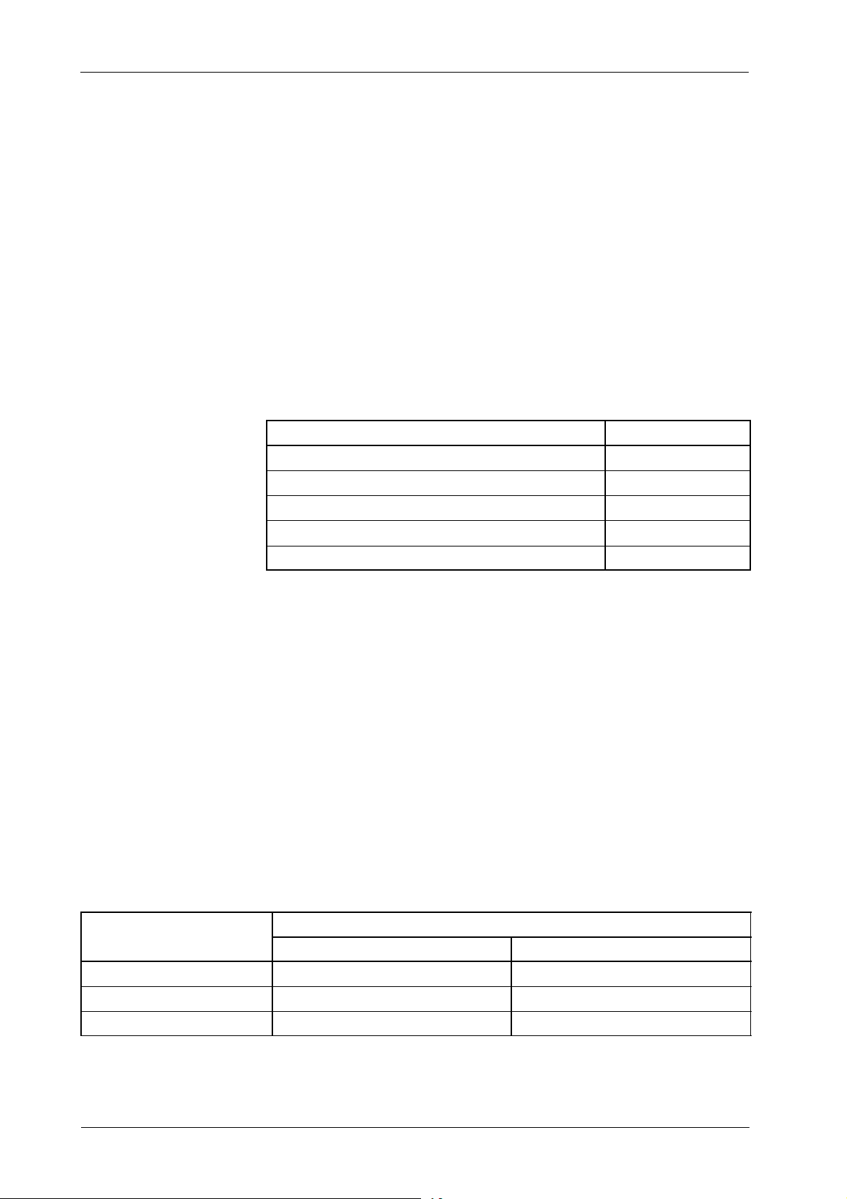
calibration accuracy. (RefertoTable2-2.)
Table 2-2
Rejection Limits Based on Meter Calibration Accuracy
METER CALIBRATION
ACCURACY
±5%
±10%
±15%
36
FOR 5 R/min (43.5 mGy/min) MAXIMUM FOR 10 R/min (87 mGy/min) MAXIMUM
4.75 R/min (41.3 mGy/min) 9.5 R/min (82.7 mGy/min)
4.50 R/min (39.2 mGy/min) 9.0 R/min (78.3 mGy/min)
4.25 R/min (37 mGy/min) 8.5R/min (74mGy/min)
REJECTIONS LIMITS
CA-1004R4
Page 41

HF Series Generators
Calibration
• E19 is used to set maximum Fluoro kV. This value is determined by the
type of TV camera and type of images desired. For general fluoroscopic
use with a conventional TV system, 120 kV is recommended. A lower
maximum setting will produce more contrast on the TV system but less
penetration for large patients.
• E25, E26, E27 are used to calibrate the Fluoro mA Display. These values
will be shown on the Fluoro mA Display during Fluoro exposures
whenever maximum PPS are selected.
Note .
The Fluoro mA Display values entered into the Extended Memory
Locations E25, E26 and E27 are also used to calculate Heat Units.
It is important to enter accurate values.
Fluoro functions are calibrated by performing the following steps:
1. Turn the generator ON.
Make sure that the Small Filament of the X-ray tube is properly
warmed-up (at less 15 minutes).
2. Set up a Dosimeter to measure the Maximum Entrance Skin Exposure
Dose Rate. Position the Probe at the center of the primary beam with the
entire active volume within the primary beam.
Place the Tube-Collimator Assembly as close as possible to the
Table-Top, fully open the Collimator Blades and align the Image
Intensifier with the light beam. Block radiation input to Image Intensifier
with a Lead Apron. (Refer to Illustration 2-4).
CA-1004R4
3. Enter in Calibration mode and read the Filament Number at 120 kV /
10 mA. Divide this value by four (4) and enter it as starting value for E17
Memory Location (Fluoro Filament Setting).
4. Select E19 Memory Location and set the maximum Fluoro kV at120 kV
or more if it is possible.
5. Exit calibration mode.
37
Page 42
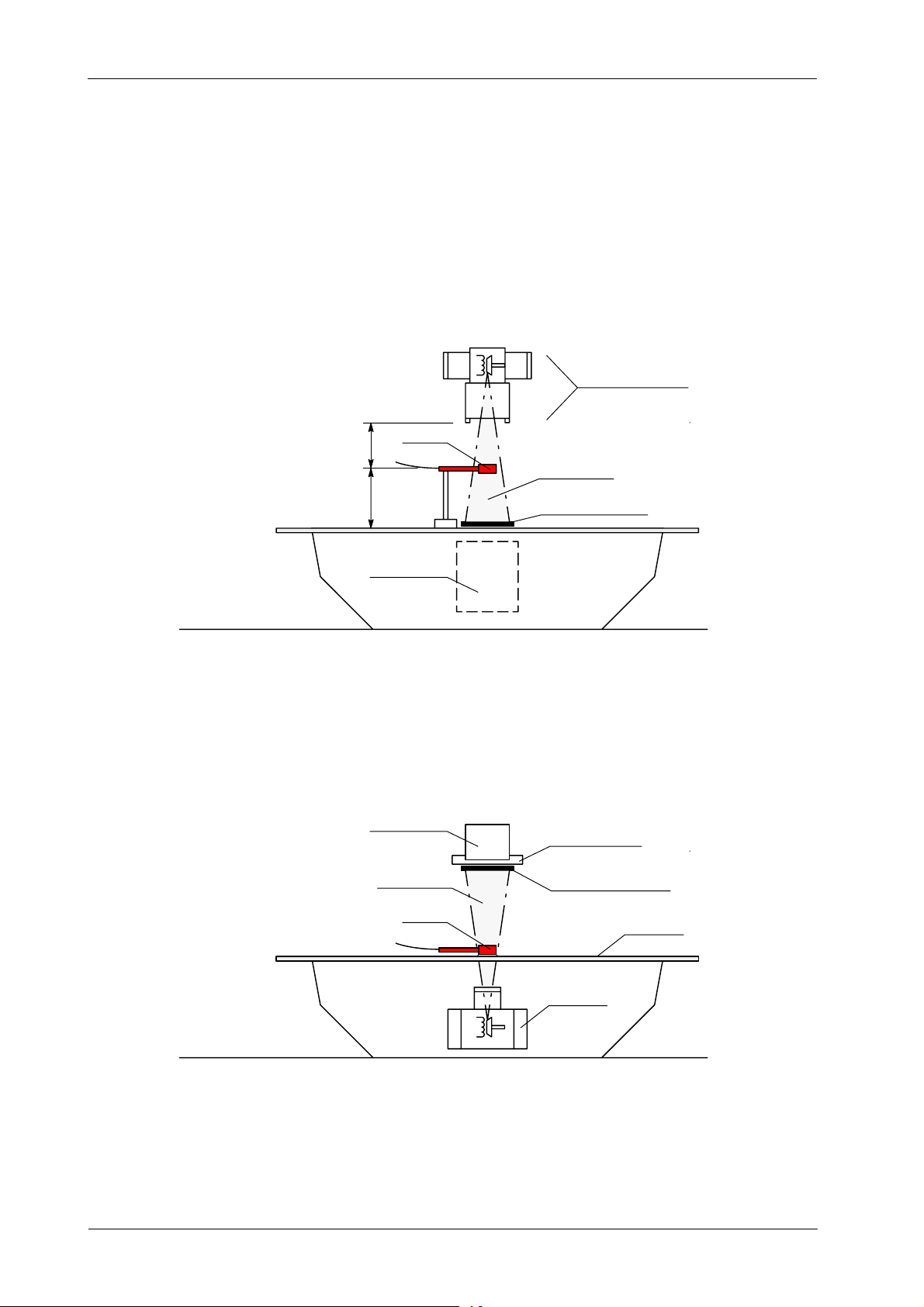
HF Series Generators
Calibration
Illustration 2-4
Fluoro Entrance Exposure Rate Test Set-up
DIAGNOSTIC SOURCE
ASSEMBLY
OVERTABLE SOURCE
SET AS CLOSE
AS POSSIBLE
PROBE
(12”)
30 cm
IMAGE SYSTEM
IMAGE SYSTEM
USEFUL BEAM
USEFUL BEAM
LEAD APRON (BLOCKER)
SPOT FILM DEVICE
LEAD APRON (BLOCKER)
38
UNDERTABLE SOURCE
PROBE
DIAGNOSTIC
SOURCE
ASSEMBLY
TABLE TOP
CA-1004R4
Page 43
HF Series Generators
Calibration
6. Select the maximum PPS and Non-ABC mode. Make a Fluoro exposure
at maximum kV that will be used in the system and measure the dose
applied, it should not be over the Rejection Limits for 10 R/min (87
mGy/min) or 5 R/min (43.5 mGy/min) (refertoTable2-2.).
In case that the value is not acquired, change the Fluoro Filament Setting
stored in E17 as required until it is correctly calibrated to that dose. Be
in mind that radiation increases or decreases in accordance to value in
E17 is increased or decreased.
7. ThemA values displayed during Fluoro exposures are stored in E25, E26
and E27 Memory Locations. The method used to obtain the Fluoro mA
values is to measure the average mA using a mA meter in Fluoro.
During Fluoro exposure, mA values are read directly with a mA Meter in
DC connected to the mA Test Points (banana plug connections) on the
HV Transformer. Only for this purpose, remove the link between the
banana plug connections on the HV Transformer.
Select the maximum PPS and Non-ABC mode. Make the following
Fluoro exposures:
G Make a Fluoro exposure at 50 kV and take note below the mA
reading, this value will be used as Fluoro mA at minimum kV (E25).
G Make a Fluoro exposure at 80 kV and take note below the mA
reading, this value will be used as Fluoro mA at medium kV (E26).
G Make a Fluoro exposure at 120 kV and take note below the mA
reading, this value will be used as Fluoro mA at maximum kV
(E27).
FL mA value at 50 kV
(E25)
FL mA value at 80 kV
(E26)
FL mA value at 120 kV
(E27)
8. Remove the Dosimeter and the Lead Apron (Blocker).
9. Enter in Calibration mode.
10. Select E19 Memory Location if it is required to reduce the value for the
maximum Fluoro kV in the installation.
CA-1004R4
11. Select the E25, E26 and E27 Memory Locations and store the respective
mA values noted before multiplied by 10 (a.e. if the mA value noted is
“3.2”, store the value “32” in the respective Memory Location).
12. Record the new values in the Data Book.
13. Exit calibration mode.
39
Page 44

HF Series Generators
Calibration
2.8 ABC CALIBRATION
The purpose of the ABC System is to maintain an optimum constant Image
Tube Output Brightness by controlling the X-ray kV during Fluoro exams,
regardless of changes in the patient opacity viewed on the TV monitor.
The closed-loop ABC System can monitor the Image Tube Output Brightness
through two ways: Photomultiplier Tube or TV Camera.
2.8.1 ABC SYSTEM WITH PHOTOMULTIPLIER TUBE
Note .
This operation requires the AEC Control Board A3012--x6/x7/x9
(Digital version).
On this system the Photomultiplier current signal, which is proportional to the
Image Tube Output Brightness, is used as brightness signal “PT Input”forthe
ABC circuitry of the Generator. (Refer to Illustration 2-5).
This analogic signal is converted to a voltage signal in the Photomultiplier
Amplifier Board and sent to a peak-detector in the AEC Control Board. The peak
signal obtained is then held through a “Sample and Hold” circuitry after a
synchronism pulse. The peak signal held is adapted to obtain finally the “ABC
IN” signal which is so the Photomultiplier signal-peak held between
synchronism pulses. This signal is then compared to a window reference.
Brightness error at the comparator output is sent as “kV Up” and “kV Down”to
the Generator where is used to drive the Fluoro kV control. The closed-loop
operation requires more or less brightness thru “kV Up” and “kV Down” demand
signals respectively. Patient Entrance Dose is automatically varied so that
optimum constant Image Tube Output Brightness is maintained.
40
CA-1004R4
Page 45
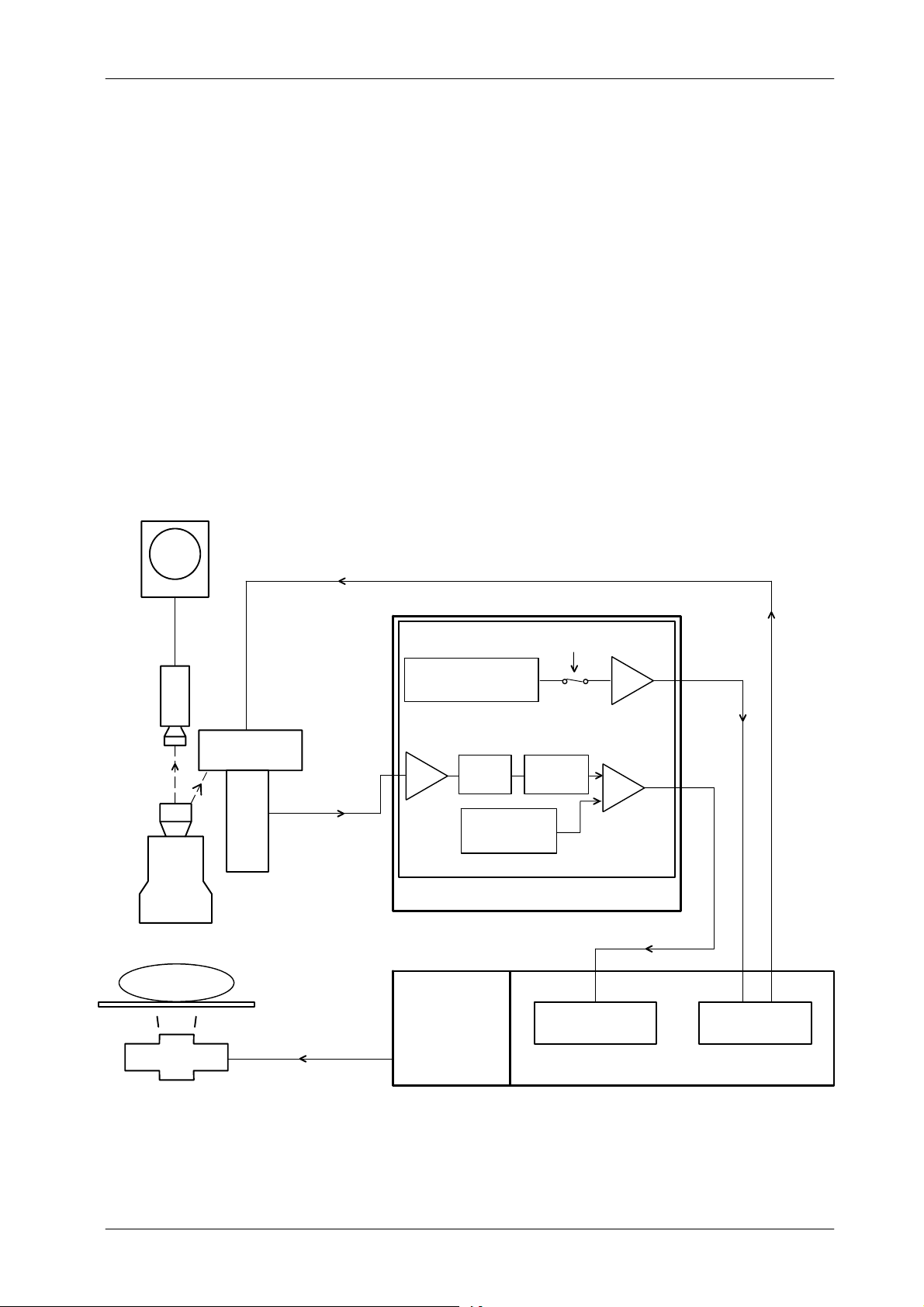
The optimum brightness level in ABC mode is set by adjusting Brightness
Control Resistor R13 on the AEC Control Board, which controls the output of
the Photomultiplier Tube High Voltage power supply on the Interface Control
Board (“PT CRL” plus 5 volts programs the output to be 0 volts, and 0 volts
programs the output to approximately --1200 volts). The window comparator
requires an input range from 0 to +10 VDC for the “ABC IN” (the optimum
brightness level will be achieved with a value between 5 and 7 VDC).
Illustration 2-5
ABC System for Photomultiplier Tube
HF Series Generators
Calibration
MONITOR
VIDEOLIGHT
TV
CAMERA
IMAGE
TUBE
PATI EN T
X-RAY TUBE
PHOTOMULTIPLIER
(Brightness signal)
AMPLIFIER
PHOTOMULTIPLIER
BOARD (A3168-- xx)
X-RAY TABLE
PT INPUT
(Photomultiplier Voltage supply)
AEC CONTROL PCB
BRIGHT. LEVEL ADJ.
R13
I/V
CONVERTER
U10
TRANSFORMER
PEAK
DETECT.
PT SPLY
WINDOW ADJ.
R11 -- R14
FL
BUFFER
U2
SAMPLE
&
HOLD
CONTROL CONSOLE
HT CONTROL PCBHV
U12
U8
WINDOW
COMPARATOR
KVUP&KVDWN
POWER MODULE
PT CRL
INTERFACE
CONTROL PCB
CA-1004R4
41
Page 46
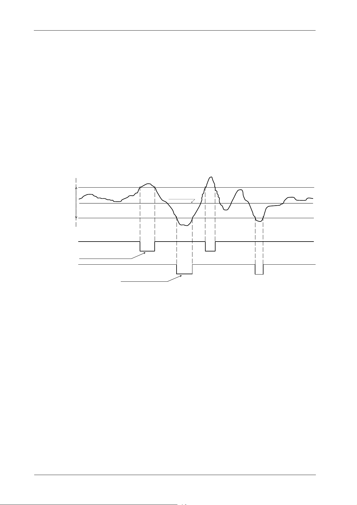
HF Series Generators
Calibration
Window reference could be adjusted first to set mid-way the brightness level
(+5 VDC), and second to increase or decrease the range of response and
sensitivity of the kV control to input variations (brightness changes). If oscillation
occurs during ABC fluoro exposure, increase the dead zone by adjusting
Resistors R11 and R14 on the AEC Control Board. (Refer to Illustration 2-6 for
ABC waveforms).
Illustration 2-6
ABC Waveforms in AEC Control Board
DWN PT reference (R11)
ABC IN
(U8--8)
UP PT reference (R14)
window reference
Brightness level
(Gain adj.)
-- kV Down (J1--19)
-- k V U P ( J 1 -- 6 )
High Logic
Command to drive
thefluorokVpDOWN
Command to drive
thefluorokVpUP
Adjust the ABC system for Photomultiplier Tube as follow:
1. Besure that the VideoSystem and the Image Intensifier are powered and
2. Set up a Dosimeter as close as possible to the Image Intensifier
Low
Logic
operating correctly.
Radiation Input to measure the Entrance Image Intensifier Exposure
Dose Rate. Position the Probe at the center of the primary beam with the
entire active volume within the primary beam.
Place the Tube-Collimator Assembly at the normal SID (1 meter), fully
open the Collimator Blades and align the Image Intensifier with the light
beam.
42
CA-1004R4
Page 47

HF Series Generators
Calibration
3. Adjust TV Camera gain for 1 volt peak-to-peak composite video output.
4. Select the maximum PPS and Non-ABC mode.
5. Place 2 mm of Copper (or equivalent homogeneous phantom) in the
Collimator Filter Holder.
6. Calculate the value of the optimum radiation (that will give optimum
brightness) usually is 2 μR/frame at 9” FOV (for more information refer to
Image System documentation).
Examples:
For 25 frame/second optimum radiation is 3 mR/min.
2 μR/frame x 25 frame/s = 50 μR/s.
50 μR/s x 60 s/min = 3000 μR/min = 3 mR/min.
For 30 frame/second optimum radiation is 3.6 mR/min.
2 μR/frame x 30 frame/s = 60 μR/s.
60 μR/s x 60 s/min = 3600 μR/min = 3.6 mR/min.
Note .
The optimum radiation value should be measured at Image Intensifier
Radiation Input. Intensifier grid should be removed, if it can not be
removed, this value should be multiplied by two or by the value specified
as Grid Absorption Factor.
7. Make a Fluoro exposure at 70 kV and measure the radiation. Optimum
radiation is obtained by modifying the Fluoro kV or the Copper thickness
in the Collimator Filter Holder. First modify the Fluoro kV, if it is more than
80 kV or less than 60 kV modify the Copper thickness in 0.1 mm (or
0.2 mm). Note the value of Fluoro KV and Copper thickness used to
obtain the optimum radiation.
Radiation increases when kV is increased or Copper thickness is
reduced.
CA-1004R4
43
Page 48

HF Series Generators
Calibration
8. Perform the following adjustments in the AEC Control Board:
a. Adjust R13 in order to obtain 6 VDC on TP3 (ABC IN).
b. Select 70 kV (or the kV obtained in step-7.) and increase 2 kV and
check the increased value of voltage in TP3 (ABC-IN) (if this value
has not been increased, increase 1 kV more). Note this value
(consider it as KV-DOWN-SEL).
c. Select 70 kV (or the kV obtained in step-7.) and decrease 2 kV and
check the decreased value of voltage in TP3 (ABC-IN) (if this value
has not been decreased, decrease 1 k V more). Note this value
(consider it as KV-UP-SEL).
d. Obtain in TP1 the same voltage noted as kV-DOWN-SEL
(DOWN PT) by adjusting the Potentiometer R11.
e. Obtain in TP2 the same voltage noted as kV-UP-SEL (UP PT) by
adjusting the Potentiometer R14.
9. Select 70 kV (or the kV obtained in step-7.) and ABC mode.
10. Make a Fluoro exposure and check that the kV does not change.
11. Stop the Fluoro exposure and select 40 kV. Make a Fluoro exposure and
check that the kV value goes to 70 kV (or the kV obtained in step-7.)
±2 kV without System problems.
12. Stop the Fluoro exposure and select 100 kV. Make a Fluoro exposure
and check that the kV value goes to 70 kV (or the kV obtained in step-7.)
±2 kV without System problems.
44
CA-1004R4
Page 49
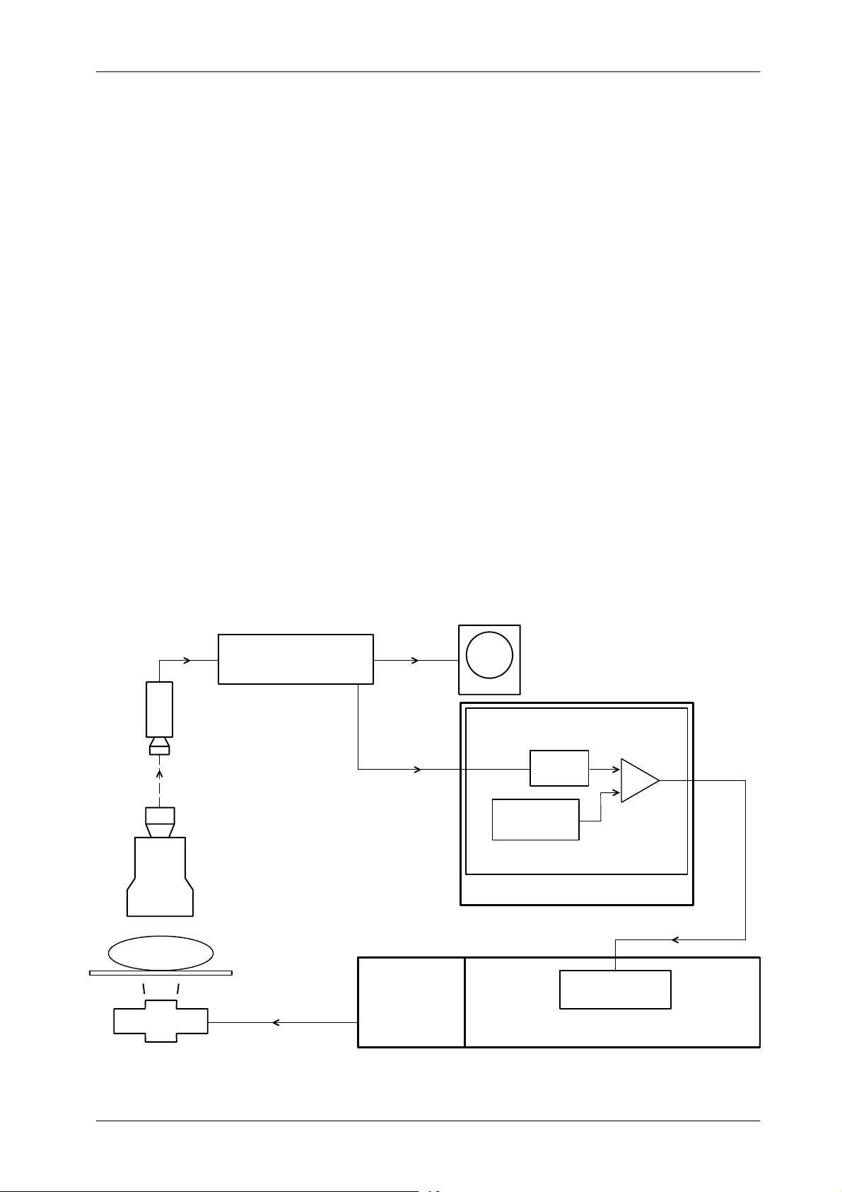
2.8.2 ABC SYSTEM WITH TV CAMERA
The ABC can be performed with an Analogic Signal Output (ABC OUT)
proportional to the brightness or with the Composite Video Signal Output from
the TV Camera.
The “ABC OUT” signal from the TV Camera is compatible with the Generator
when the range is from 0 VDC (dark image) to 10 VDC (bright image) and the
Optimum Brightness is achieved at around 6 VDC.
When a TV Camera without a direct “ABC OUT” signal is used, the Composite
Video signal (which amplitude is proportional to the image tube output
brightness) is sent to an RF Adaptation Board where it is transformed into an
“ABC OUT” analogic signal. In this case, the brightness level is taken from a
rectangular window from the center of the raster. (Refer to Illustration 2-7).
This analogic signal in the AEC Control Board (“PT Input” in Board
A3012--x1/x2/x5 and “ABC OUT” in Board A3012--x6/x7/x9) is filtered, and
compared to a window reference. Brightness error at the comparator output is
sent as “kV Up” and “kV Down” to the Generator where is used to drive the fluoro
kV control. The closed-loop operation requires more or less brightness thru “kV
Up” and “kV Down” demand signals respectively. Patient entrance dose is
automatically varied so that constant image tube output brightness is
maintained.
HF Series Generators
Calibration
Illustration 2-7
ABC System for TV Camera
RF ADAPTATION BOARD
TV
CAMERA
LIGHT
IMAGE
TUBE
PATI EN T
X-RAY TABLE
X-RAY TUBE
VIDEO OUTVIDEO IN
PT INPUT
(Brightness signal)
HV
TRANSFORMER
MONITOR
AEC CONTROL PCB
ABC OUT
WINDOW ADJ.
FILTER
R5 -- C11
R11 -- R14
WINDOW
COMPARATOR
U8
CONTROL CONSOLE
KVUP&KVDWN
HT CONTROL PCB
POWER MODULE
CA-1004R4
45
Page 50
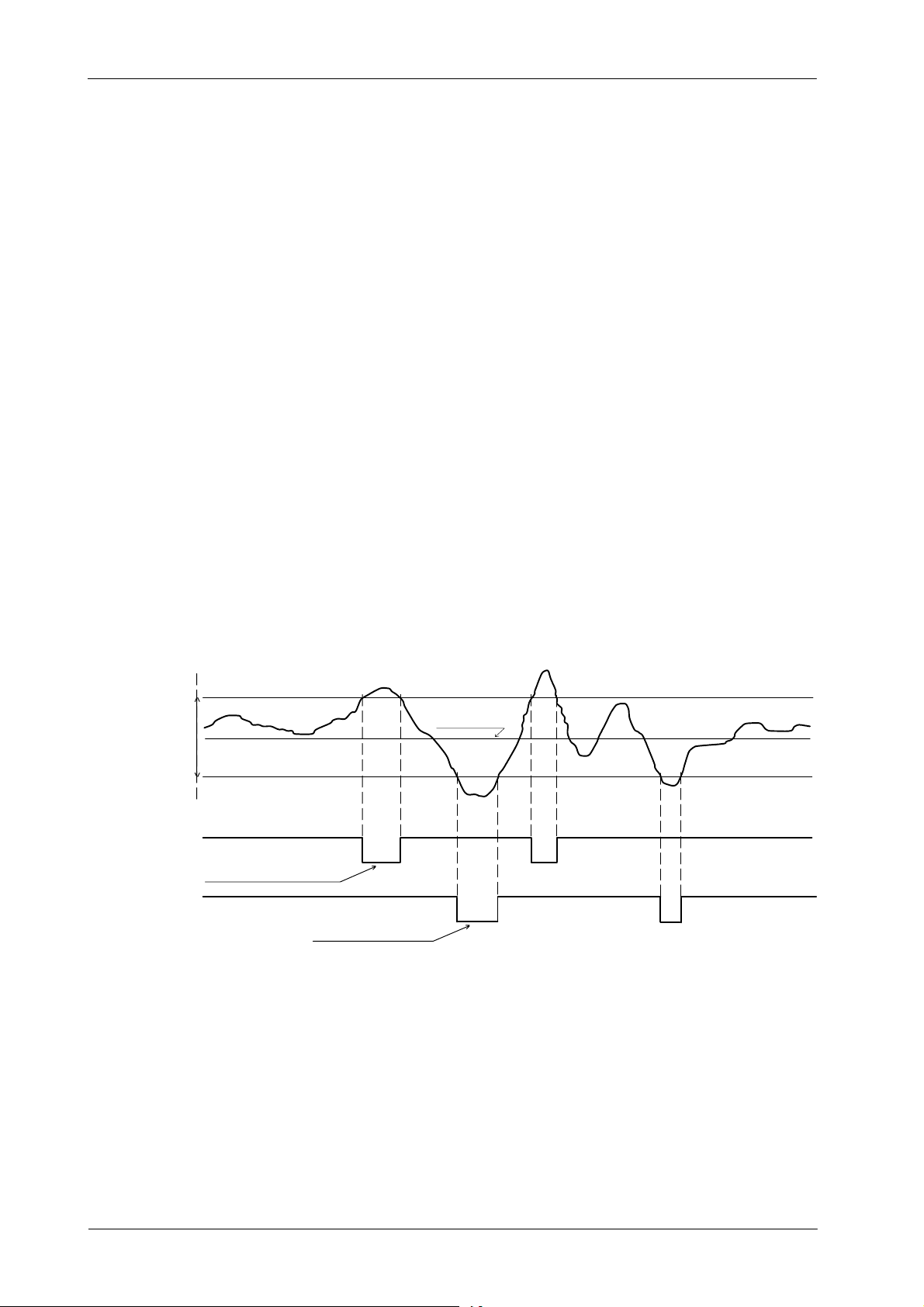
HF Series Generators
Calibration
The optimum brightness level in ABC mode is set by adjusting the gain at R27
on the RF Adaptation Board. The “ABC OUT” signal requires an input range
from 0 to +10 VDC (the stabilized value will be between 5 and 7 VDC).
Window reference could be adjusted first to set mid-way the brightness level (+6
VDC), and second to increase or decrease the range of response and sensitivity
of the kV control to input variations (brightness changes). If oscillation occurs
during ABC fluoro exposure, increase the dead zone by adjusting R11 and R14
on the AEC Control Board. (Refer to Illustration 2-8 for ABC waveforms)
For system interface, refer to RF Adaptation Board. Adjust ABC System
according to the following procedures.
Illustration 2-8
ABC Waveforms in AEC Control Board
DWN PT reference (R11)
ABC IN
(U8--8)
-- kV Down (J1--19)
-- k V U P ( J 1 -- 6 )
UP PT reference (R14)
window reference
Command to drive
thefluorokVpDOWN
High Logic
Command to drive
thefluorokVpUP
Brightness level
(Gain adj.)
Low
Logic
46
CA-1004R4
Page 51

HF Series Generators
Calibration
2.8.2.1 ABC SYSTEM ADJUSTMENT WITH ABC SIGNAL FROM TV CAMERA COMPATIBLE WITH
THE GENERATOR
1. Besure that the VideoSystem and the Image Intensifier are powered and
operating correctly.
2. Set up a Dosimeter as close as possible to the Image Intensifier
Radiation Input to measure the Entrance Image Intensifier Exposure
Dose Rate. Position the Probe at the center of the primary beam with the
entire active volume within the primary beam.
Place the Tube-Collimator Assembly at the normal SID (1 meter), fully
open the Collimator Blades and align the Image Intensifier with the light
beam.
3. Adjust TV Camera gain for 1 volt peak-to-peak composite video output.
4. Set Jumper JP21 in position B on the RF Adaptation Board.
5. Select the maximum PPS and Non-ABC mode.
6. Place 2 mm of Copper (or equivalent homogeneous phantom) in the
Collimator Filter Holder.
7. Calculate the value of the optimum radiation (that will give optimum
brightness) usually is 2 μR/frame at 9” FOV (for more information refer to
Image System documentation).
Examples:
For 25 frame/second optimum radiation is 3 mR/min.
2 μR/frame x 25 frame/s = 50 μR/s.
50 μR/s x 60 s/min = 3000 μR/min = 3 mR/min.
For 30 frame/second optimum radiation is 3.6 mR/min.
2 μR/frame x 30 frame/s = 60 μR/s.
60 μR/s x 60 s/min = 3600 μR/min = 3.6 mR/min.
CA-1004R4
The optimum radiation value should be measured at Image Intensifier
Radiation Input. Intensifier grid should be removed, if it can not be
removed, this value should be multiplied by two or by the value specified
as Grid Absorption Factor.
47
Page 52

HF Series Generators
Calibration
8. Make a Fluoro exposure at 70 kV and measure the radiation. Optimum
radiation is obtained by modifying the Fluoro kV or the Copper thickness
in the Collimator Filter Holder. First modify the Fluoro kV, if it is more than
80 kV or less than 60 kV modify the Copper thickness in 0.1 mm (or
0.2 mm). Note the value of Fluoro KV and Copper thickness used to
obtain the optimum radiation.
Note .
Radiation increases when kV is increased or Copper thickness is
reduced.
9. Perform the adjustment for the window test as specified on the TV
Camera manuals. This window defines the area of the image where the
brightness will be captured for the ABC and it should be the 25% of the
image area.
10. Adjust the TV Camera to obtain +6 VDC (or the voltage supplied by the
TV Camera as optimum brightness) on TP3 (ABC IN) on the AEC Control
Board (Refer the TV Camera manuals).
11. Perform the following adjustments in the AEC Control Board:
a. Select 70 kV (or the kV obtained in step-8.) and increase 2 kV and
check the increased value of voltage in TP3 (ABC-IN) (if this value
has not been increased, increase 1 kV more). Note this value
(consider it as KV-DOWN-SEL).
b. Select 70 kV (or the kV obtained in step-8.) and decrease 2 kV and
check the decreased value of voltage in TP3 (ABC-IN) (if this value
has not been decreased, decrease 1 k V more). Note this value
(consider it as KV-UP-SEL).
48
c. Obtain in TP1 the same voltage noted as kV-DOWN-SEL (DOWN
PT) by adjusting the Potentiometer R11.
d. Obtain in TP2 the same voltage noted as kV-UP-SEL (UP PT) by
adjusting the Potentiometer R14.
12. Select the 70 kV (or the kV obtained in step-8.) and ABC mode.
13. Make a Fluoro exposure and check that the kV does not change.
14. Stop the Fluoro exposure and select 40 kV. Make a Fluoro exposure and
check that the kV value goes to 70 kV (or the kV obtained in step-8.)
±2 kV without System problems.
15. Stop the Fluoro exposure and select 100 kV. Make a Fluoro exposure
and check that the kV value goes to 70 kV (or the kV obtained in step-8.)
±2 kV without System problems.
CA-1004R4
Page 53

HF Series Generators
Calibration
2.8.2.2 ABC SYSTEM ADJUSTMENT WITH ABC SIGNAL FROM TV CAMERA NOT COMPATIBLE
WITH THE GENERATOR
1. Besure that the VideoSystem and the Image Intensifier are powered and
operating correctly.
2. Set up a Dosimeter as close as possible to the Image Intensifier
Radiation Input to measure the Entrance Image Intensifier Exposure
Dose Rate. Position the Probe at the center of the primary beam with the
entire active volume within the primary beam.
Place the Tube-Collimator Assembly at the normal SID (1 meter), fully
open the Collimator Blades and align the Image Intensifier with the light
beam.
3. Adjust TV Camera gain for 1 volt peak-to-peak composite video output.
4. Set on the RF Adaptation Board, Jumpers JP21 in position “A” and JP20
in position “B” (for negative ABC signal) or in position “C” (for positive
ABC signal).
5. Select the maximum PPS and Non-ABC mode.
6. Place 2 mm of Copper (or equivalent homogeneous phantom) in the
Collimator Filter Holder.
7. Calculate the value of the optimum radiation (that will give optimum
brightness) usually is 2 μR/frame at 9” FOV (for more information refer to
Image System documentation).
Examples:
For 25 frame/second optimum radiation is 3 mR/min.
2 μR/frame x 25 frame/s = 50 μR/s.
50 μR/s x 60 s/min = 3000 μR/min = 3 mR/min.
For 30 frame/second optimum radiation is 3.6 mR/min.
2 μR/frame x 30 frame/s = 60 μR/s.
60 μR/s x 60 s/min = 3600 μR/min = 3.6 mR/min.
CA-1004R4
The optimum radiation value should be measured at Image Intensifier
Radiation Input. Intensifier grid should be removed, if it can not be
removed, this value should be multiplied by two or by the value specified
as Grid Absorption Factor.
49
Page 54

HF Series Generators
Calibration
8. Make a Fluoro exposure at 70 kV and measure the radiation. Optimum
radiation is obtained by modifying the Fluoro kV or the Copper thickness
in the Collimator Filter Holder. First modify the Fluoro kV, if it is more than
80 kV or less than 60 kV modify the Copper thickness in 0.1 mm (or
0.2 mm). Note the value of Fluoro KV and Copper thickness used to
obtain the optimum radiation.
Note .
Radiation increases when kV is increased or Copper thickness is
reduced.
9. Perform the adjustment for the window test as specified on the TV
Camera manuals. This window defines the area of the image where the
brightness will be captured for the ABC and it should be the 25% of the
image area.
10. Select the 70 kV (or the kV obtained in step-8.) and Non-ABC mode.
11. Adjust R29 (OFFSET) on the RF Adaptation Board to have 0 VDC in TP7.
12. Adjust gain at R27 (Gain) on the RF Adaptation Board to make the “ABC
OUT” signal equal to +6 VDC. Measure “ABC OUT”inTP-7ofRF
Adaptation Board or in TP3 (”ABC IN”) of the AEC Control Board.
13. Perform the following adjustments in the AEC Control Board:
a. Select 70 kV (or the kV obtained in step-8.) and increase 2 kV and
check the increased value of voltage in TP3 (ABC-IN). Note this
value (consider it as KV-DOWN-SEL).
b. Select 70 kV (or the kV obtained in step-8.) and decrease 2 kV and
check the decreased value of voltage in TP3 (ABC-IN). Note this
value (consider it as KV-UP-SEL).
50
c. Obtain in TP1 the same voltage noted as kV-DOWN-SEL (DOWN
PT) by adjusting the Potentiometer R11.
d. Obtain in TP2 the same voltage noted as kV-UP-SEL (UP PT) by
adjusting the Potentiometer R14.
14. Select the 70 kV (or the kV obtained in step-8.) and ABC mode.
15. Make a Fluoro exposure and check that the kV does not change.
16. Stop the Fluoro exposure and select 40 kV. Make a Fluoro exposure and
check that the kV value goes to 70 kV (or the kV obtained in step-8.)
±2 kV without System problems.
17. Stop the Fluoro exposure and select 100 kV. Make a Fluoro exposure
and check that the kV value goes to 70 kV (or the kV obtained in step-8.)
±2 kV without System problems.
CA-1004R4
Page 55

HF Series Generators
2.8.2.3 ABC SYSTEM ADJUSTMENT WITH NO ABC SIGNAL FROM TV CAMERA
1. Besure that the VideoSystem and the Image Intensifier are powered and
operating correctly.
2. Set up a Dosimeter as close as possible to the Image Intensifier
Radiation Input to measure the Entrance Image Intensifier Exposure
Dose Rate. Position the Probe at the center of the primary beam with the
entire active volume within the primary beam.
Place the Tube-Collimator Assembly at the normal SID (1 meter), fully
open the Collimator Blades and align the Image Intensifier with the light
beam.
3. Adjust TV Camera gain for 1 volt peak-to-peak composite video output.
Calibration
4. Set on the RF Adaptation Board, Jumpers JP21 in position “A” and JP20
in position “A”.
5. Select the maximum PPS and Non-ABC mode.
6. Place 2 mm of Copper (or equivalent homogeneous phantom) in the
Collimator Filter Holder.
7. Calculate the value of the optimum radiation (that will give optimum
brightness) usually is 2 μR/frame at 9” FOV (for more information refer to
Image System documentation).
Examples:
For 25 frame/second optimum radiation is 3 mR/min.
2 μR/frame x 25 frame/s = 50 μR/s.
50 μR/s x 60 s/min = 3000 μR/min = 3 mR/min.
For 30 frame/second optimum radiation is 3.6 mR/min.
2 μR/frame x 30 frame/s = 60 μR/s.
60 μR/s x 60 s/min = 3600 μR/min = 3.6 mR/min.
CA-1004R4
The optimum radiation value should be measured at Image Intensifier
Radiation Input. Intensifier grid should be removed, if it can not be
removed, this value should be multiplied by two or by the value specified
as Grid Absorption Factor.
51
Page 56

HF Series Generators
Calibration
8. Make a Fluoro exposure at 70 kV and measure the radiation. Optimum
radiation is obtained by modifying the Fluoro kV or the Copper thickness
in the Collimator Filter Holder. First modify the Fluoro kV, if it is more than
80 kV or less than 60 kV modify the Copper thickness in 0.1 mm (or
0.2 mm). Note the value of Fluoro KV and Copper thickness used to
obtain the optimum radiation.
Note .
Radiation increases when kV is increased or Copper thickness is
reduced.
9. Perform the adjustment for the window test. This window defines the
area of the image where the brightness will be captured for the ABC.
a. Calculate the image area πr
2
(clear circle on the monitor). (r=circle
radius).
2
b. Calculate the 25% of the image area ( πr
c. Calculate the sides of the window: l = πr
/4).
2
∕4(I= side of square).
d. Mark the calculated area on the monitor (square).
e. Position jumper JP18 of RF Adaptation Board in “A”. A window will
be displayed on the monitor.
f. Adjust in the RF Adaptation Board the following potentiometers to
move the window under the frame marked on the monitor in
step--d:
52
-- R1 potentiometer (vertical position)
-- R2 potentiometer (vertical width)
-- R3 potentiometer (horizontal position)
-- R4 potentiometer (horizontal width)
g. Once the window is configured, place JP18 in “B” again at RF
Adaptation Board.
10. Select the 70 kV (or the kV obtained in step-8.) and Non-ABC mode.
11. Adjust the gain at R27 on the RF Adaptation Board to make the “ABC
OUT” signal equal to +6 VDC. Measure “ABC OUT”inTP7ofRF
Adaptation Board or in TP3 (”ABC IN”) of the AEC Control Board.
CA-1004R4
Page 57

HF Series Generators
12. Perform the following adjustments in the AEC Control Board:
a. Select 70 kV (or the kV obtained in step-8.) and increase 2 kV and
check the increased value of voltage in TP3 (ABC-IN) (if this value
has not been increased, increase 1 kV more). Note this value
(consider it as KV-DOWN-SEL).
b. Select 70 kV (or the kV obtained in step-8.) and decrease 2 kV and
check the decreased value of voltage in TP3 (ABC-IN) (if this value
has not been decreased, decrease 1 k V more). Note this value
(consider it as KV-UP-SEL).
c. Obtain in TP1 the same voltage noted as kV-DOWN-SEL (DOWN
PT) by adjusting the Potentiometer R11.
d. Obtain in TP2 the same voltage noted as kV-UP-SEL (UP PT) by
adjusting the Potentiometer R14.
Calibration
13. Select the 70 kV (or the kV obtained in step-8.) and ABC mode.
14. Make a Fluoro exposure and check that the kV does not change.
15. Stop the Fluoro exposure and select 40 kV. Make a Fluoro exposure and
check that the kV value goes to 70 kV (or the kV obtained in step-8.)
±4 kV without System problems.
16. Stop the Fluoro exposure and select 100 kV. Make a Fluoro exposure
and check that the kV value goes to 70 kV (or the kV obtained in step-8.)
±4 kV without System problems.
CA-1004R4
53
Page 58

HF Series Generators
Calibration
2.9 FINAL CHECKS
Verify that all Configuration and Calibration data have been properly stored in
memory.
1. Enter in calibration mode and check that the values noted for the
“Filament Current Numbers” and “Extended Memory Locations” tables
of the Data Book are the same that the values displayed and stored in
memory. Press the “AEC Reset” button to read the stored values.
2. Exit from calibration mode and Service mode.
3. Turn the Generator OFF and verify position of dip switches on the HT
Controller Board are:
G Dip switch 3000SW2-2 in “Off” position (enables Filament and
Rotor Interlocks).
G Dip switch 3000SW2-4 in “Off” position (Digital mA Loop Closed).
4. Set the Test dip switch 3024SW2-3 on the ATP Console CPU Board in
“Off” position to place the Generator in normal operating mode.
54
CA-1004R4
 Loading...