

Page 1

Technical Publication
CF-1004R4
Configuration
HF Series Generators
Page 2
REVISION HISTORY
REVISION DATE REASON FOR CHANGE
0 APR 1, 2001 First edition
1 FEB 10, 2003 Documentation update
2 MAY 20, 2004 Documentation update
3 APR 1, 2005 Text revision
HF Series Generators
Configuration
4
This Document is the English original version, edited and supplied by the manufacturer.
The Revision state of this Document is indicated in the code number shown at the bottom of this page.
AUG 1, 2005 Anode Stator Configuration
ADVISORY SYMBOLS
The following advisory symbols will be used throughout this manual. Their
application and meaning are described below.
DANGERS ADVISE OF CONDITIONS OR SITUATIONS THAT
IF NOT HEEDED OR AVOIDED WILL CAUSE SERIOUS
PERSONAL INJURY OR DEATH.
ADVISE OF CONDITIONS OR SITUATIONS THAT IF NOT
HEEDED OR AVOIDED COULD CAUSE SERIOUS PERSONAL
INJURY, OR CATASTROPHIC DAMAGE OF EQUIPMENT OR
DATA.
CF-1004R4
Advise of conditions or situations that if not heeded or
avoided could cause personal injury or d amage to equipment
or data.
Note . Alert readers to pertinent facts and conditions. Notes represent
information that is important to know but which do not necessarily
relate to possible injury or damage to equipment.
Page 3

HF Series Generators
Configuration
TABLE OF CONTENTS
Section Page
1 INITIAL CONFIGURATION PROCEDURE 1...................................
1.1 Configuration and Test Switches 3......................................
1.1.1 3024SW1 - ATP Console CPU Board 3...........................
1.1.2 3024SW2 - ATP Console CPU Board 3...........................
1.1.3 3024SW3 - ATP Console CPU Board 4...........................
1.1.4 3024SW4 - ATP Console CPU Board 4...........................
1.1.5 3000SW2 - HT Controller Board 4...............................
1.2 Anode Starter Configuration 5..........................................
1.2.1 High Speed Version 5..........................................
1.2.2 Low Speed Version 5..........................................
1.3 Workstations Configuration 8...........................................
1.4 Basic Configuration of Generator Boards 12...............................
1.5 AEC Configuration 13..................................................
1.6 Fluoro Configuration 14................................................
2 EXTENDED MEMORY SETTING 17...........................................
2.1 Extended Memory Locations 17.........................................
2.2 How to Enter and Store Data in the Extended Memory 19...................
2.3 X-ray Tube Type Selection 20...........................................
2.3.1 X-ray Tube Insert Protection Curves 20............................
2.3.2 Programming of Rotor Acceleration Time and Filament Setting Time 21
2.4 Limit of Maximum kW 25...............................................
3 FILAMENT AND ANODE TESTS 27..........................................
3.1 Filament Driver 27.....................................................
3.2 Focal Spots Configuration and Test 27...................................
3.3 Anode Rotation Test 28................................................
4 X-RAY TUBE DATA 31......................................................
CF-1004R4
i
Page 4

HF Series Generators
Configuration
ii
CF-1004R4
Page 5
HF Series Generators
Configuration
SECTION 1 INITIAL CONFIGURATION PROCEDURE
Configuration provides the initial settings for extended memory and checkout
procedures that must be carried out prior to making X-ray exposures.
Functional characteristics of this Generator are defined at the time of
installation.
Calibration data and some configuration data are stored in the extended
memory area on a non-volatile memory chip (U3-EEPROM) located on the
HT Controller Board in the Power Cabinet.
When the initial setup and checkout has been completed the Generator will be
ready for Calibration.
Note .
Record all the configuration settings in the Data Book.
DO NOT SUPPLY THE MAIN POWER UNTIL SPECIFICALLY
INSTRUCTED TO DO SO IN THIS DOCUMENT.
THE MAIN CAPACITORS OF THE HIGH VOLTAGE INVERTER
RETAIN A LARGE PORTION OF THEIR CHARGE FOR
APPROX. 3 MINUTES AFTER THE UNIT IS TURNED OFF.
The Generator configuration is determined by:
• X-ray Tube(s) number, model and use.
• System requirements (Bucky, Tomo, AEC, ...)
• Maximum kV, mA, kW.
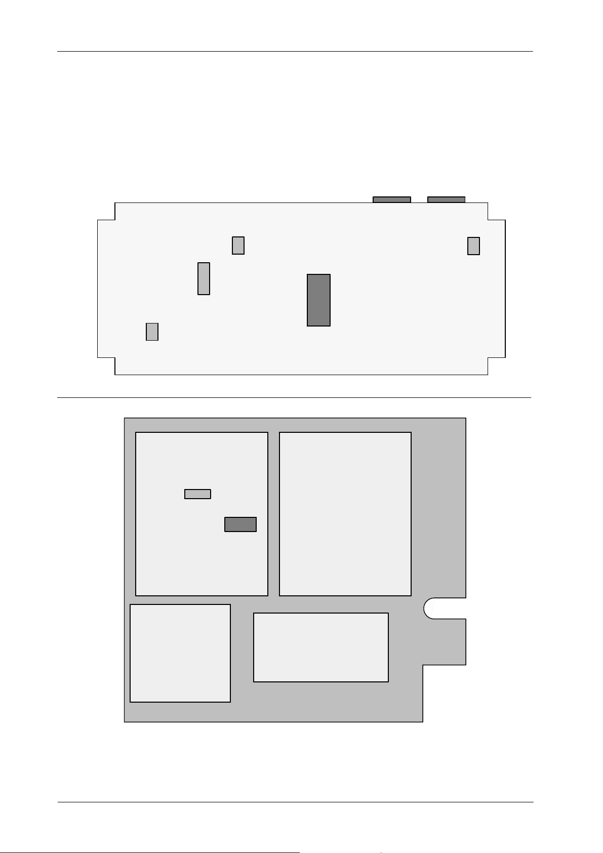
Specific versions of U24-EPROM on the ATP Console CPU Board and
U5-EPROM on the HT Controller Board are based on the Generator
configuration. (Refer to Illustration 1-1).
CF-1004R4
The system configuration and test switches are:
DIP SWITCH LOCATION FUNCTION
3024SW1 - ATP Console CPU Board System Configuration
3024SW2 - ATP Console CPU Board Test
3024SW3 - ATP Console CPU Board No used for Configuration
3000SW2 - HT Controller Board System Configuration and Test
1
Page 6
HF Series Generators
Configuration
Illustration 1-1
EPROM and Switch locations
J7 J8
3024SW2
3024SW1
3024SW3
3000SW2
U24
ATP CONSOLE CPU BOARD -- A3024
U5
3024SW4
HT CONTROLLER -- A3000
FILAMENT DRIVER
A3004
2
INTERFACE CONTROL -- A3009
POWER SUPPLY
POWER CABINET -- FRONT PANEL
CF-1004R4
Page 7
HF Series Generators
1.1 CONFIGURATION AND TEST SWITCHES
ATP Console Dip Switches must be configured with the Generator turned OFF,
and they are read when the Generator is turned ON again.
1.1.1 3024SW1 - ATP CONSOLE CPU BOARD
Set dip switch 3024SW1 in accordance with the Table 1-1.
Table 1-1
System Configuration Dip Switch 3024SW1 on the ATP Console CPU Board
3024SW1 POSITION OPEN (OFF) CLOSED (ON)
1 60 Hz
2 --
*1)
Normal -- Application mode.
Exposures are inhibited when
Door Interlock Switch is opened.
50 Hz
*1)
Configuration
3 Not used. Set in “OFF” position. Not used.
4 Not used. Set in “OFF” position. Not used.
Note.-- *1) This switch is related with the frequency of the Rotor Controller. For Generators with High Speed Starter (LV-
DRAC) or Generators Powered through Batteries with Stand-Alone set always SW1-1 to 60 Hz, in the rest of Generators set SW1-1 in accordance with the Power Line Frequency.
1.1.2 3024SW2 - ATP CONSOLE CPU BOARD
Set dip switch 3024SW2 verifying that each position is set as Table 1-2.
Table 1-2
Test Dip Switch 3024SW2 on the ATP Console CPU Board
3024SW2 POSITION OPEN (OFF) CLOSED (ON)
Skips reception with the HT Controller. Use only
1
2
for display purposes, troubleshooting or Demo
Consoles when there is no Power Module. Be
sure that J3 connector is not plugged to the ATP
Console CPU Board.
Tick Sound (button / command acknowledge) is
not emitted by the ATP Console CPU Board.
Normal -- Application mode.
Tick Sound (button / command acknowledge) is
emitted by the ATP Console CPU Board.
3 Normal -- Application mode.
4
CF-1004R4
kV Log (Renard) Scale Mode for kV variation
(kV changes in logarithmic steps).
Service Mode .
In this mode and some Consoles, i f the selected
Focal Spot indicator is blinking it means that
Generator is operating in High Speed. It will help
to service engineer during Configuration and
Calibration procedures.
kV Lineal Scale Mode for kV variation (Normal
mode) (kV changes one by one).
3
Page 8
HF Series Generators
Configuration
1.1.3 3024SW3 - ATP CONSOLE CPU BOARD
Dip Switch 3024SW3 is not used for configuration but all their switches must be
set in “Off” position.
1.1.4 3024SW4 - ATP CONSOLE CPU BOARD
Dip Switch 3024SW4 is not used for configuration but all their switches must be
set in “Off” position.
1.1.5 3000SW2 - HT CONTROLLER BOARD
HT Controller Dip Switches can be configured while the Generator is ON except
Dip Switch 3000SW2-1.
Set dip switch 3000SW2 as indicated in Table 1-3.
Table 1-3
Test Dip Switch 3000SW2 on the HT Controller Board in the Power Module
3000SW2
POSITION
1 Normal.
2 Normal. Bypasses: Filament, Rotor Ready, Error E11.
3 Normal -- Not used. Not used.
4 Normal -- Digital mA Loop Closed Digital mA Loop Open / Filament Current Constant
5 125 kV
6 All Generators except for two Tubes RAD. Only for Generators with two Tubes RAD.
7 Boosting Tube--1 (Filament) No Boosting Tube--1 (Filament)
8 Boosting Tube--2 (Filament) No Boosting Tube--2 (Filament)
Notes.-- *1) Set in Closed (On) position only for Calibration and Testing procedures when indicated in the Service Manual.
*2) Note that SW2-1 in Closed (On) position is only set to program the Rotor Boost Time and Filament Setting Time,
therefore it changes the functions of Switches SW2-2 and SW2-4 to SW2-8.
Refer to Sections 2.3 and 2.3.2 and configure the Rotor Boost Time and Filament Setting Time switches after X-ray
Tube Type selection.
*4)
OPEN (OFF) CLOSED (ON)
Programming of Rotor Boost Time and
Filament Setting Time
*4)
150 kV
*1) *2)
*5)
*5)
*1) *3)
*1)
*3) This turns off the filament so no radiation will be produced during the exposure.
WARNING: THE kV OUTPUT OF THE HV TRANSFORMER WILL BE WHAT IS SET ON THE CONSOLE. IF THE
X-RAY TUBE HV CABLES ARE NOT CONNECTED TO THE HV TRANSFORMER, FILL COMPLETELY BOTH
HV RECEPTACLES WITH HV OIL.
*4) Set SW2-5 according to the Generator kV rating (refer to the Generator model and/or specifications).
*5) Set to “No Boosting” when using X-ray Tubes with Small Focal Spot smaller than 0.6 .
4
CF-1004R4
Page 9
1.2 ANODE STARTER CONFIGURATION
1.2.1 HIGH SPEED VERSION
The High Speed Starter (LV-DRAC - Low Voltage Digital Rotating Anode
Controller) is required for High Speed X-ray Tube(s). Connections between the
LV-DRAC and the Generator Cabinet are factory made, so any wire connection
is required.
1.2.2 LOW SPEED VERSION
For Low Speed, voltage and capacitor is factory set to 220 VAC, 30 μF. Other
voltages require their corresponding adaptation. In all cases, refer to X-ray Tube
Product Data.
HF Series Generators
Configuration
Check that capacitor values of the Low Speed Stator
correspond to the values recommended by the X-ray Tube
manufacturer. Also, the Rotor speed must be the indicated by
manufacturer. If needed replace the capacitors.
CONFIGURATION FOR ONE OR TWO TUBES WITH THE SAME
STARTING VOLTAGE (110 VAC OR 220 VAC)
When the stator requires a voltage of 110 VAC(a.e. X-ray Tube
Toshiba E7239 / E7240 / E7242 / E7252 / E7299 / E7813 / E7865)
perform the following modifications:
If the Power Input Transformer 6T2 is for using with power
lines up to 240 VAC (part number 50509030), remove the wire
connected to terminal 6T2 - 4 (230 VAC RTR) and connect it to
terminal 6T2 - 3 or 6T2-8 (110 VAC).
If the Power Input Transformer 6T2 is for using with power
lines up to 530 VAC (part number 50509029), remove the wire
connected to terminal 6T2 - 4 (230 VAC RTR) and connect it to
terminal 6T2 - 40 (110 VAC).
CF-1004R4
For X-ray Tube Toshiba E7252 or E7813 (or when it is
required) replace also the Fuse F1 (6A) on the LF-RAC Board
by another fuse of 10 A.
This change affects to all the Tubes connected to Generator.
5
Page 10
HF Series Generators
Configuration
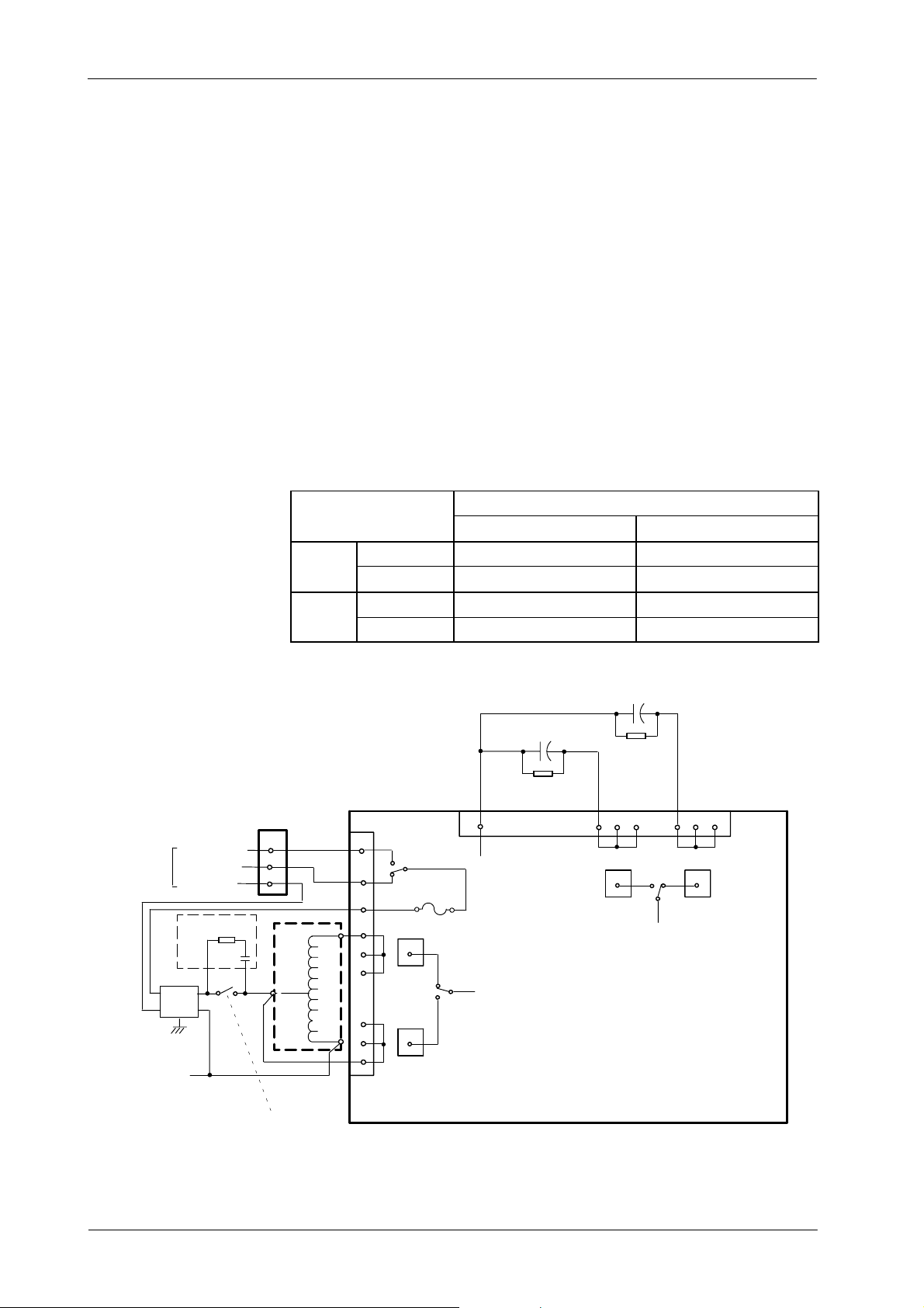
CONFIGURATION FOR TWO TUBE STATORS WITH DIFFERENT
STARTING VOLTAGE AND CAPACITOR
For Generators equipped with a LF-RAC module for two X-ray Tubes, with
possible selection of voltage and capacitor jumpers on the LF-RAC Board, set
jumpers according to the respective X-ray Tube(s) as indicated in next pages.
The DC Brake of the Low Speed Starter (LF-RAC) can be removed by
desoldering CR6 on the LF-RAC Board (refer to schematic 543020xx). In this
case, the Tube will remain coasting.
STARTING VOLTAGE OF 220 VAC AND 330 VAC
(A “Kit of 330 VAC” is required with this configuration).
TUBE MODEL
220 VAC , 30 μF 330 VAC , 15 μF
TUBE-1
TUBE-2
VO LTAG E TB2-T1 with TB1-5 or TB1-6 TB2-T1 with TB1-8 or TB1-9
CAPACITOR TB3-T1 with TB1-12 or TB1-13 TB3-T1 with TB1-15 or TB1-16
VO LTAG E TB2-T2 with TB1-5 or TB1-6 TB2-T2 with TB1-8 or TB1--9
CAPACITOR TB3-T2 with TB1-12 or TB1-13 TB3-T2 with TB1-15 or TB1-16
(S1,2--D2)
T1/T2 COMM
(to 10TS2)
NOTE.-- 10J7 and 10J8 are
230 VAC RTR
60 VAC RTR
0VACRTR
10RC1
100 nF
1KV
10LF2
214
2
3
aerial connectors
47
2w
10K1
1
10J8
1
2
3
10T3
220V
330V
TB1
1
2
3
7
8
9
KACC
K1--1
TB2
T1
Tube 1
TB1
F1
T6A
NOTE.-- 10T3, 10C5--1 and
10R4--1 for 330 VAC Stator
10
KCT
K2--1
10C5--2
30uF
10R4--2
1 Mohm, 2w
LF--RAC BOARD
11 12
TB3
Tube 2
10C5--1
15uF
10R4--1
1 Mohm, 2w
30uF
13
T2
KCT
K2--3
14 15
TB3
Tube 1
15uF
16
T1
10A1
6
0V
TB2
5
4
T2
Tube 2
6
CF-1004R4
Page 11
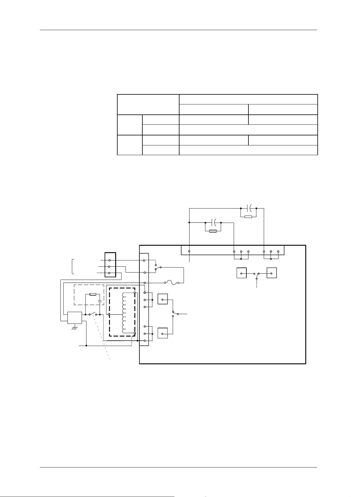
STARTING VOLTAGE OF 220 VAC AND 110 VAC
(A “Kit of 110 VAC” is required with this configuration).
TUBE MODEL
220 VAC , 30 μF 150 VAC , 30 μF
HF Series Generators
Configuration
(S1,2--D2)
T1/T2 COMM
(to 10TS2)
NOTE.-- 10J7 and 10J8 are
230 VAC RTR
60 VAC RTR
0VACRTR
10RC1
100 nF
1KV
10LF2
214
10K1
2
3
aerial connectors
10J8
47
2w
1
1
2
3
10T3
150 V
TUBE-1
TUBE-2
220V
0V
VO LTAG E TB2-T1 with TB1-5 or TB1-6 TB2-T1 with TB1-8 or TB1-9
CAPACITOR TB3-T1 with TB1-12 or TB1-13
VO LTAG E TB2-T2 with TB1-5 or TB1-6 TB2-T2 with TB1-8 or TB1--9
CAPACITOR TB3-T2 with TB1-12 or TB1-13
10C5--1
15uF
10C5--2
TB1
1
2
3
7
8
9
KACC
K1--1
TB2
T1
Tube 1
TB1
F1
T6A
KCT
K2--1
10
30uF
10R4--2
1Mohm,2w
LF--RAC BOARD
11 12
TB3
Tube 2
10R4--1
1 Mohm, 2w
30uF
13
T2
KCT
K2--3
14 15
TB3
Tube 1
15uF
16
T1
10A1
6
TB2
5
4
T2
Tube 2
CF-1004R4
7
Page 12

HF Series Generators
Configuration
1.3 WORKSTATIONS CONFIGURATION
The workstations can be configured according to the customer preferences or
default.
Each combination of Tube / Device / Ion Chamber is associated to one
workstation in the system. If during the system configuration some push-button
has not been related to one workstation (value “Tube -- 0”), these push-buttons
won’t be able to be selected during operation.
The different combinations of X-ray Tubes, Devices, Ion Chambers and kV
Tracking (optional) are configured from the Console as described below:
CUSTOMIZED CONFIGURATION
Note .
This procedure has to be performed always that “ATP Console
CPU Board” is replaced by a new one.
1. With the Generator OFF, set dip switch 3024SW2-3 on the ATP Console
CPU Board in “On” position to permit the service mode.
2. In accordance with the Console model, enter in configuration mode by
holding pressed the “ON” push-button and then simultaneously press
“+2” and “-- 2 ” density (or “Slow” and “Fast” Film/Screen) push-buttons,
until all the workstations push-buttons are illuminated.
3. Select the first workstation to be configured, by pressing the respective
push-button or c ombination of push-buttons, only these push-buttons
blink and the Console shows one of the following values:
8
CF-1004R4
Page 13
HF Series Generators
V
DEVICES--
V
ION
V
kVTRACKIN
G
DISPLAY FUNCTION VAL UE DESCRIPTION
0 No-configured workstation
Configuration
1stValue TUBES
nd
2
alue
rd
3
alue
DEVICES --
WORKING MODE
ION
CHAMBERS
1 Tube-1
2 Tube-2
0--Direct Direct (No Bucky)
1 -- Bucky 1 Bucky-1
2 -- Bucky 2 Bucky-2
3--STDTomo Standard Tomo
4--STDRF Standard RF (Spot Film Device)
5--DSI Digital Rad and Fluoro
6--Cine Cine
7--DSA DSA
0 No AEC
1 Ion Chamber-1
2 Ion Chamber-2
3 Ion Chamber-3
4 Ion Chamber-4
5 Photomultiplier
1 Formula-1
*2)
*2)
*1)
*2)
2 Formula-2
3 Formula-3
th
4
alue
Notes:
-- Some of listed values are not configurable depending on the Generator model .
*1) Only when the Tomo is controlled from the Generator. In this case, the workstation has to be configured as Tube “1” or “2”,
Device “STD Tomo” and Ion Chamber “0”.
If the Tomo is controlled from the Table, the workstation has to be configured as Tube “2”, Device “STD RF” and Ion Chamber “0”.
*2) These Devices are only available for Generators provide with interface option for Digital Systems.
kVTRACKING
(OPTIONAL)
4 Formula-4
5 Formula-5
6 Formula-6
7 Formula-7
8 Formula-8
4. Set the new value by pressing the corresponding “Increase”or
“Decrease” push-buttons.
Note .
In some Consoles, “No Bucky” is selected when neither of the
“Bucky” nor “Tomo” push-buttons are selected.
CF-1004R4
9
Page 14

HF Series Generators
Configuration
5. Select the next workstations to be configured and set the respective
values of each one.
6. Exposures made from workstations configured with:
G Device “Direct (No Bucky), Bucky-1, Bucky-2 and Standard Tomo”
are only enabled with the internal “Preparation” and “Exposure”
signals controlled by the Handswitch or Rad Footswitch.
G Device “Standard RF” and “DSI”areonly enabled with the
external signals for “Preparation”, “RAD Exposure” and “Fluoro
Exposure”. Fluoro can only be made from this Device
selection.
G Device “Infimed: DSI, Cine, DSA”areonly enabled with the
external “Digital Preparation” and “Exposure” signals connected
to Terminal Block 4TS3 of the Generator Cabinet.
Note .
7. Select one of the workstation configured as available and in accordance
with the Console model exit configuration mode by simultaneously
pressing “+2” and “-- 2 ”(or “Slow” and “Fast” Film/Screen) push-buttons,
then a double-bip will sound and the Console go on with the starting
process.
1) Optional “Tomo / Bucky Adaptation Board” (in the Power
Cabinet) is required to configure more than two Buckys or one
Tomo Device in the system.
For systems without the optional “Tomo / Bucky Adaptation
Board” only can work directly with two Buckys, and the value
assigned to them must be “1” and “2” in the second value.
2) TOMO must be always related to Bucky-1. Only one TOMO can
be used in the system, so only one of the workstations should be
configured with the value “3” in the second value.
3) Optional “AEC Control Board” (connected to the Console CPU
Board) is required to configure any Ion Chamber.
10
Optional “AEC Adaptation Board” is required to configure any
no-standard or more than one Ion Chambers in the system.
CF-1004R4
Page 15

HF Series Generators
Configuration
DEFAULT CONFIGURATION
Default configuration sets some default values to each workstation. It only
should be used to re-initialize the workstation configuration when the complete
configuration has been lost or it is not possible to select any workstation.
1. With the Generator OFF, set dip switch 3024SW2-3 on the ATP Console
CPU Board in “On” position to permit the service mode.
2. In accordance with the Console model, enter in configuration mode by
holding pressed the “ON” push-button and then simultaneously press
“+2” and “-- 2 ” density (or “Slow” and “Fast” Film/Screen) push-buttons,
until all the workstations push-buttons are illuminated.
3. Press the “AEC Reset” push-button once, and in accordance with the
Console model exit configuration mode by simultaneously pressing “+2”
and “-- 2 ”(or “Slow” and “Fast” Film/Screen) push-buttons, then a
double-bip w ill sound and the console go on with the starting process.
4. It is recommended to perform a proper configuration of each workstation
in the system after a default configuration.
CF-1004R4
11
Page 16
HF Series Generators
INTERFACECONTRO
L
ATPCONSOLECPU
Configuration
1.4 BASIC CONFIGURATION OF GENERATOR BOARDS
The following Jumpers should be factory set or removed to configure the
Generator boards for working with the application. Checks the below jumpers
in the Generator boards.
GENERATOR BOARDS JUMPERS POSITION
JP1andJP2in“2”
HT CONTROLLER
FILAMENT CONTROL JP1in“A”
JP3, JP5 and JP6 in “2” and JP4 in “1” : for Compact Generators.
JP3, JP5 and JP6 in “1” and JP4 in “2” : for Vertical Generators.
W1 in “2--3”
W2 in “1--2”
W3 to W10 in “A” : for positive High Voltage supply for Ion Chamber
W3 to W10 in “B” : for negative High Voltage supply for Photomultiplier Tube
JP1, JP2 and JP3 in “B” (soldered)
JP4 in “B” (Cam-Sync)
JP5 in “B” (for ATS Digital System set JP5 in “C”)
JP6 in “A” (soldered)
Connector J8 configured for RS232 so: JP9, JP10 and JP11 in “A”.
JP7, JP8, JP21 and JP22 do not matter jumpers position
JP12 removed
JP13 installed (set)
JP14 installed (soldered)
JP15, JP16, JP17 and JP18 removed
JP19 in “A” (soldered)
12
CF-1004R4
Page 17
1.5 AEC CONFIGURATION
A
A
A
,
Configure the following Jumpers on the “AEC Control Board” (located over the
“ATP Console CPU Board”) and on the “AEC Adaptation Board” when this
option is installed in the Generator Cabinet.
AEC C ONTROL BOARD (A3012--01/02/05)
JUMPER DESCRIPTION
JP1 A FOR TV CAMERA
B FOR PHOTOMULTIPLIER
C FOURTH ION CHAMBER & ATS--DIG
JP2 A FOR TV CAMERA
B FOR PHOTOMULTIPLIER
JP4 A FOR PHOTOMULTIPLIER -- AEC
B FOR ION CHAMBER -- AEC & ATS--DIG
JP3 A FOR HIGH SENSITIVITY
B FOR LOW SENSITIVITY
NOTE: HIGH SENSITIVITY IS > 2 V / mR (> 0.223 V / μGy) (a.e. Vacutec Ion Chamber)
LOW SENSITIVITY IS < 2 V / mR (< 0.223 V / μGy) (refer to Ion Chamber documentation)
3012-05: JP1-C, JP2A3012-02: JP1-A, JP2-A AND JP4-A FOR ABC WITH TV CAMERA
A3012-01: JP1-B, JP2-B AND JP4-A FOR ABC WITH PHOTOMULTIPLIER
JP3-A FOR AEC WHEN USING ION CHAMBER WITH HIGH SENSITIVITY
JP3-B FOR AEC WHEN USING ION CHAMBER WITH LOW SENSITIVITY
ND JP4-B FOR FOURTH ION CHAMBER &ATS--DIG
HF Series Generators
Configuration
AEC C ONTROL BOARD (A3012--06/07/09)
JUMPER DESCRIPTION
JP1 A FOR TV CAMERA
B FOR PHOTOMULTIPLIER
C EXTERNAL kV CONTROL
JP2 A FOR HIGH SENSITIVITY
B FOR LOW SENSITIVITY
JP3 B FOR NORMAL OPERATION JP3-B FOR NORMAL OPERATION
JP4 A FOR NORMAL OPERATION JP4-A FOR NORMAL OPERATION (Only in A3012-06)
NOTE: HIGH SENSITIVITY IS > 2 V / mR (> 0.223 V / μGy) (a.e. Vacutec Ion Chamber)
LOW SENSITIVITY IS < 2 V / mR (< 0.223 V / μGy) (refer to Ion Chamber documentation)
JP1-A FOR ABC WITH TV CAMERA
JP1-B FOR ABC WITH PHOTOMULTIPLIER
JP1-C FOR ABC WITH EXTERNAL kV UP & DOWN CONTROL
JP2-A FOR AEC WHEN USING ION CHAMBER WITH HIGH SENSITIVITY
JP2-B FOR AEC WHEN USING ION CHAMBER WITH LOW SENSITIVITY
CF-1004R4
13
Page 18
HF Series Generators
Configuration
AEC ADAPTATION BOARD (A3263--03)
ION CHAMBER TYPE
IC1 = IC2 = IC3 = IC4 B B B
IC1 = IC2 = IC3 B B A
IC1 = IC2 B A A
IC1 ≠ IC2 ≠ IC3 ≠ IC4 A A A
ION CHAMBER OUTPUT
NO-OFFSET ADJUSTMENT A A A A
OFFSET ADJUSTMENT B B B B
TEST POINT AND POTENTIOMETER
(ONLY IF JUMPER IS IN “B” POSITION)
JP3, JP4, JP7, JP8 JP1, JP2, JP5, JP6 JP13, JP14, JP15, JP16
JP9 (IC1) JP10 (IC2) JP11 (IC3) JP12 (IC4)
TP1 -- R11 TP2 -- R8 TP4 -- R2 TP12 -- R5
JUMPERS POSITION
JUMPERS POSITION
1.6 FLUORO CONFIGURATION
Fluoro configuration depends on position of jumpers W1 and W2 in the “Fluoro
CPU Board” and jumper JP4 in the “Console CPU Board”, as indicated below:
JUMPERS IN FLUORO CPU BOARD
(A3213-XX)
W1 ABC not enable ABC enable
W2 Always inserted (installed)
JUMPERS IN ATP CONSOLE CPU BOARD (A3024-XX)
JP4 Always in “B” position -- Camera
INSERTED REMOVED
14
CF-1004R4
Page 19
Also, configure the following Jumpers on the optional “RF Adaptation Board”
JP1
0,JP1
2
according to the Board version.
RF ADAPTATION BOARD (A3514--03)
JUMPER POSITION FUNCTION
Set all jumpers +24 VDC for the inputs PREP ORDER, RAD ORDER, and FLUORO ORDER
JP1, JP3, JP4,
JP8, JP9,
JP13, JP14
JP2
JP5
JP6
JP7
JP11
JP15
JP16
JP17
JP18
JP19
JP20
JP21
JP22
JP23
Remove all jumpers
,
Set only JP1,
JP8 and JP12
Removed External supply for PREP / RAD / FLUORO ORDER
Removed When JP21 in position B
Removed To reduce noise in the ABC circuitry
230 VAC for the inputs PREP ORDER, RAD ORDER, and FLUORO ORDER
115 VAC for the inputs PREP ORDER, RAD ORDER, and FLUORO ORDER
Set Generator +24 VDC for PREP / RAD / FLUORO ORDER
A ZOOM 1 output selected from Generator (--9 IN SEL)
B ZOOM 1 output selected from Table or external control
A ZOOM 2 output selected from Generator (--6 IN SEL)
B ZOOM 2 output selected from Table or external control
A ZOOM 3 output selected from Generator (--4 IN SEL)
B ZOOM 3 output selected from Table or external control
A LIH output selected from an external enable signal
B LIH output selected for Last Image Hold function
A LIH output selected from an external enable signal
B LIH output selected for Last Image Hold function
A EXP ON/END output active for only RAD exposure
B EXP ON/END output active for Fluoro and RAD exposure
A For EXP ON output active along the RAD exposure
B For EXP END output active about 50 ms pulse at the end of the RAD exposure
A For ABC Window adjustment
B For normal operation
A Pulsed Fluoro sync. from the Line sync.
B Pulsed Fluoro sync. from the TV Camera sync.
C Pulsed Fluoro sync. from an external sync. (digital, etc.)
A For ABC OUT signal from the video in
B For ABC OUT signal from a negative System ABC signal
C For ABC OUT signal from a positive System ABC signal
A ABC OUT signal generated from a System ABC signal
B ABC OUT signal incoming directly from the System
Set When JP21 in position A
Set Normal position
HF Series Generators
Configuration
CF-1004R4
15
Page 20
HF Series Generators
,
,
Configuration
RF ADAPTATION BOARD (A3514--04)
JUMPER POSITION FUNCTION
JP1, JP3, JP4,
JP8, JP9,
JP10, JP12,
JP13, JP14
JP2
JP5
JP6
JP7
JP11
JP15
JP16
JP17
JP18
JP19
JP20
JP21
JP22
JP23
JP24
Set all jumpers +24 VDC for the inputs PREP ORDER, RAD ORDER, and FLUORO ORDER
Remove all jumpers 230 VAC for the inputs PREP ORDER, RAD ORDER, and FLUORO ORDER
Set only JP1,
JP8 and JP12
Set Generator +24 VDC for PREP / RAD / FLUORO ORDER
Removed External supply for PREP / RAD / FLUORO ORDER
A ZOOM 1 output selected from Generator (--9 IN SEL)
B ZOOM 1 output selected from Table or external control
A ZOOM 2 output selected from Generator (--6 IN SEL)
B ZOOM 2 output selected from Table or external control
A ZOOM 3 output selected from Generator (--4 IN SEL)
B ZOOM 3 output selected from Table or external control
A LIH output selected from an external enable signal
B LIH output selected for Last Image Hold function
A LIH output selected from an external enable signal
B LIH output selected for Last Image Hold function
A EXP ON/END output active for only RAD exposure
B EXP ON/END output active for Fluoro and RAD exposure
A For EXP ON output active along the RAD exposure
B For EXP END output active about 50 ms pulse at the end of the RAD exposure
A For ABC Window adjustment
B For normal operation
A Pulsed Fluoro sync. from the Line sync.
B Pulsed Fluoro sync. from the TV Camera video.
C Pulsed Fluoro sync. from an external sync. (TV Camera, digital, etc.)
A For ABC OUT signal from the video in
B For ABC OUT signal from a negative System ABC signal
C For ABC OUT signal from a positive System ABC signal
A ABC OUT signal generated from a System ABC signal
B ABC OUT signal incoming directly from the System
Set When JP21 in position A
Removed When JP21 in position B
Set Normal position
Removed To reduce noise in the ABC circuitry
A Normal position
B For Fluoro order enable
115 VAC for the inputs PREP ORDER, RAD ORDER, and FLUORO ORDER
16
CF-1004R4
Page 21

SECTION 2 EXTENDED MEMORY SETTING
2.1 EXTENDED MEMORY LOCATIONS
Miscellaneous configuration and calibration data are stored in the Extended
Memory Locations. It is recommended to note the values factory stored in each
Memory Location. (RefertoTable2-1)
HF Series Generators
Configuration
Note .
Note .
Note .
Note .
For Generators with only one Radiographic X-ray Tube, this Tube
have to be configured, calibrated and used as Tube-1.
Generators with one or two X-ray Tube(s) for only Radiographic
use do not require to store any value in the Memory Locations:
E19, E25, E26, E27.
For Generators with a Fluoroscopic X-ray Tube, this Tube have to
be configured, calibrated and used as Tube-2.
For these Generators, the value of the E17 Memory Location is not
readable as “Tube-2 -- Filament stand-by (Autocalibrated)”.
Generators with a single X-ray Tube for Fluoroscopy / Spot Film
requires to store the r espective values of the Memory Locations:
-- E01: Tube-1 -- RAD filament stand-by (Autocalibrated).
-- E17: Tube-2 -- Fluoro filament setting.
-- E18: Tube-2 -- Fluoro Tube type.
-- E29 and E31: Tube-2 -- Exposure Time adjustments.
-- Other required Memory Locations.
CF-1004R4
17
Page 22
HF Series Generators
*
Configuration
Table 2-1
Extended Memory Locations
MEMORY LOCATION FUNCTION VALUE
E01 TUBE-1 -- RAD filament stand-by (Autocalibrated. Not field changeable)
E02 TUBE-1 -- RAD Tube type
E03 Low Digital mA Loop Closed (from 10 mA to 80 mA)
E04 AEC-1 calibration
E05 High Digital mA Loop Closed (from 100 mA)
E06 kV Loop
E07 Maximum kW (Factory set. Only field changeable to lower value)
E08 AEC-1 tracking
E09 AEC-2 calibration
E10 AEC-2 tracking
E11 AEC Compression Device - Time adjustment
E12 AEC Density Scale
E13 TUBE-1 -- Exposure Time adjustment - Delay
E14 Not used.
E15 TUBE-1 -- Exposure Time adjustment - Ceq kV
E16 Not used.
E17
E18 TUBE-2 -- RAD or FLUORO Tube type
E19 Maximum FLUORO kV
E20 AEC-3 calibration
E21 Not used.
E22 Not used.
E23 AEC-4 calibration / Photomultiplier AEC calibration (SF camera)
E24 AEC-3 tracking / AEC-4 tracking (equal value for both)
E25 FLUORO mA display c alibration at 50 kV
E26 FLUORO mA display c alibration at 80 kV
TUBE-2 -- RAD filament stand-by (Autocalibrated. Not field changeable)
TUBE-2 -- FLUORO filament setting
E27 FLUORO mA display calibration at 120 kV
E28 Not used.
E29 TUBE-2 -- Exposure Time adjustment - Delay
E30 Not used.
E31 TUBE-2 -- Exposure Time adjustment - Ceq kV
E32 Not used.
* Note.-- For Fluoroscopic use, value in E17 means “Fluoro filament setting” and must be manually set
18
CF-1004R4
Page 23

HF Series Generators
2.2 HOW TO ENTER AND STORE DATA IN THE EXTENDED MEMORY
The Extended Memory data are entered from the Console when the unit is in
service mode. Access to memory locations as indicated below:
1. Turn the Generator OFF and set the Test dip switch 3024SW2-3 on the
ATP Console CPU Board in “On” position to permit the service mode.
2. Turn the Generator ON by pressing the “Power On” push-button on the
Console.
3. In accordance with the Console model, enter calibration mode by
simultaneously pressing “+2” and “-- 2 ” density (or “Slow” and “Fast”
Film/Screen) push-buttons. The indicator lamp for the selected
workstation will be flash confirming that the Generator is in the calibration
mode.
Configuration
Note .
In calibration mode, only the kV and mA parameters can be
modified, values for Time and mAs are factory programmed.
4. Increase the mA value beyond the maximum mA position, one step for
each of the memory locations. The mA Display will show the first
Extended Memory location (E01), they will continue sequentially as the
“Increase mA” push-button is pressed.
The values stored in each location are displayed on the kV Display after
pressing the “AEC Reset” push-button or after pressing the “+1”or“-- 1 ”
(or “Increase” and “Decrease”) density push-buttons. Since these
push-buttons are also used to increase or decrease the stored values
one number should be added or subtracted from the r eading to obtain the
stored value.
5. Select the new value by pressing “+1”or“-- 1 ” (or “Increase” and
“Decrease”) density push-buttons. Each time these push-buttons are
depressed the displayed value (on the kV Display) is increased or
decreased one step.
6. Store the new value by pressing the “AEC Reset” push-button
(Check-summ function).
CF-1004R4
Note .
If the “AEC Reset” push-button is not pressed after a new value is
selected, no modified data will be retained and the kV Display
reverts to either the selected kV value or the original data.
7. Exitcalibration mode by simultaneously pressing “+2” and “-- 2 ” (or “Slow”
and “Fast” Film/Screen) push-buttons.
8. Turn the Generator OFF and set Test dip switch 3024SW2-3 on the ATP
Console CPU Board in “Off” position to place the Generator in normal
mode.
19
Page 24
HF Series Generators
Configuration
2.3 X-RAY TUBE TYPE SELECTION
2.3.1 X-RAY TUBE INSERT PROTECTION CURVES
In order to properly select the X-ray Tube Insert Protection Curves for the Tubes
connected to the Generator, perform the following procedure:
1. Selectone workstation of the corresponding X-ray Tube to be configured.
2. Enterincalibration mode and select the respective memory location (E02
or E18) (memory location is shown on the mA Display).
3. Identify in Section 4 “X-ray Tube Data”, the X-ray Tube that is being
installed and note its Tube type number.
4. Set the Tube number by pressing “+1”or“-- 1 ” (or “Increase” and
“Decrease”) density push-buttons until the correct number is showed in
the kV Display.
Note .
5. Store the value by pressing the “AEC Reset” push-button.
6. Verify that the Tube code (ID) showed in the mAs Display is the same of
the Tube code listed in Section 4 “X-ray Tube Data”. The Tube code (ID)
can be only read for the selected X-ray Tube after pressing the “AEC
Reset” push-button.
7. If required, repeat this procedure for the other X-ray Tube.
8. Exit calibration mode.
For Generators with High Speed Starter, configure NOW the
High Speed X-ray Tubes by setting the respective dip
switches 3243SW1 and / or 3243SW2 on the “Control DRAC
Board”. (Refer to “LV-DRAC - Digital Rotating Anode
Controller” document).
Record configuration data for E02 and E18 in the Data Book.
20
CF-1004R4
Page 25
HF Series Generators
Configuration
2.3.2 PROGRAMMING OF ROTOR ACCELERATION TIME AND FILAMENT SETTING TIME
Rotor Acceleration Time is determined by the X-ray Tube and
Rotor characteristics and it must be considered when the
Generator is a bout to be configured. X-ray Tube could be
permanently damaged unless the required RPM are reached
before an exposure. (Refer to technical information of the
X-ray Tube).
Dip Switch 3000SW2 on the HT Controller Board is used to program:
• Rotor Acceleration Time. That depends on Stator voltage, Stator
frequency, and Stator type, quality of X-ray Tube bearings, and X-ray
Tubeanode size. A reed tachometer can be used to determine the anode
RPM. Customer application will determine the acceleration times. Be
sure that the Rotor Acceleration Times meet all requirements for
anticipated customer applications.
Note .
• Rad Filament Setting Time. Sometimes, after configuration of the Rotor
Acceleration Time, it is required to increase the Filament Setting Time to
the following time. For that, configure the respective switches again. This
adjustment avoids Error-12.
• Fluoro R otor Hold-over Time.
• Fluoro Filament Hold-over Time.
They are only allowed when dip switch 3000SW2-1 is in “Closed”
(On) position after power the Generator OFF and back ON again.
LOW SPEED STARTER VERSION (LF-RAC)
Rotor Acceleration Time is programmable from 0.8 to 2.7 seconds. After this
time the Rotor is hold running in maintaining mode as long as “Prep”isactive.
Fluoro Rotor and Filament Hold-Over Time can be also programmed to run for
1 minute or not at all, after releasing the Fluoro Pedal.
CF-1004R4
1. Turn the Generator OFF and note current settings of the dip switch
3000SW2 on the HT Controller Board.
Dip switch 3000SW2-1 should not be switched with power on.
21
Page 26
HF Series Generators
Configuration
2. Set dip switches 3000SW2-1 and 3000SW2-2 as indicated below, in
order to enable the selection of times with the Low Speed Starter.
3000SW2-1 (selection enable) 3000SW2-2 (Low Speed Starter)
ON OFF
Note .
With Low Speed operation, Rotor Acceleration Time, Filament
Setting Time, and Fluoro Rotor and Filament Hold-Over Time are
configured with dip switch 3000SW2 per this instruction.
3. Configure the Rotor and Filament Times by setting the dip switches
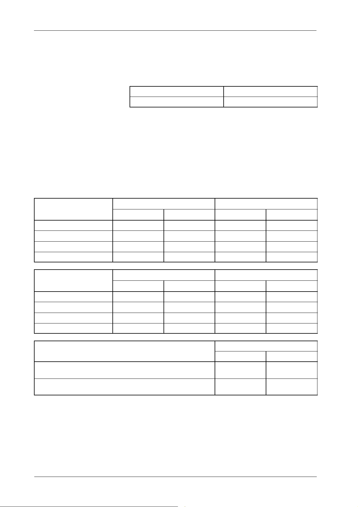
3000SW2-4 through 3000SW2-8 per Table 2-2.
Table 2-2
Low Speed: Configuration of Rotor and Filament Times
ROTORACCELERATION TIME
TUBE-1
AND FILAMENT SETTING TIME
0.8 seconds
1.2 seconds
1.8 seconds
2.7 seconds
TUBE-2
ROTORACCELERATION TIME
AND FILAMENT SETTING TIME
0.8 seconds
OPEN (OFF) CLOSED (ON) OPEN (OFF) CLOSED (ON)
OPEN (OFF) CLOSED (ON) OPEN (OFF) CLOSED (ON)
3000SW2-7 3000SW2-8
- -
- -
- -
- -
3000SW2-5 3000SW2-6
- -
1.2 seconds
1.8 seconds
2.7 seconds
FLUORO ROTORAND FILAMENT HOLD-OVER TIME
After releasing the Fluoro Pedal, the Rotor stops and the Filament Current goes
back to stand-by.
After releasing the Fluoro Pedal, 1 minutes passes before the Rotor stops
and the Filament Current goes back to stand-by.
Note .
- -
- -
- -
The Rotor Acceleration Time and Filament Setting Time is factory
set to 1.8 seconds. Maintain this value when it is unknown or not
provided with the X-ray Tube documentation.
Record switch configuration in the Data Book.
3000SW2-4
OPEN (OFF) CLOSED (ON)
-
-
22
CF-1004R4
Page 27
HF Series Generators
Configuration
4. To validate previous configuration, turn the Generator ON, wait until
Error--01 (E01) appears on the Console and turn the Generator OFF.
Set dip switch 3000SW2 to the original settings as recorded
in step-1. (Refer to Section 1.1.5 for the normal settings of Dip
Switch 3000SW2).
HIGH SPEED STARTER VERSION (LV-DRAC)
1. Turn the Generator OFF.
Note .
2. Configure the High Speed X-ray Tube according to the LV-DRAC
documentation, specially dip switches 3243SW1 and 3243SW2 of the
LV-DRAC (refer to this document in the Service Manual).
3. Record current settings of the dip switch 3000SW2 on the HT Controller
Board.
Dip switch 3000SW2-1 should not be switched with power on.
4. Set dip switches 3000SW2-1 and 3000SW2-2 as indicated below, in
order to enable the selection of times with the High Speed Starter.
3000SW2-1
(selection enable)
ON ON
3000SW2-2
(High Speed Starter)
With High Speed operation:
CF-1004R4
-- Rotor Acceleration Time is related to the High Speed X-ray
Tubes configured in the LV-DRAC (HSS).
-- Fluoro and Spot Film Rotor Hold-Over Time is configured in the
LV-DRAC (HSS).
-- Rad Filament Setting Time and Fluoro Filament Hold-over Time
are configured with dip s witch 3000SW2 per this instruction.
23
Page 28
HF Series Generators
TUBE-
1
TUBE-
2
Configuration
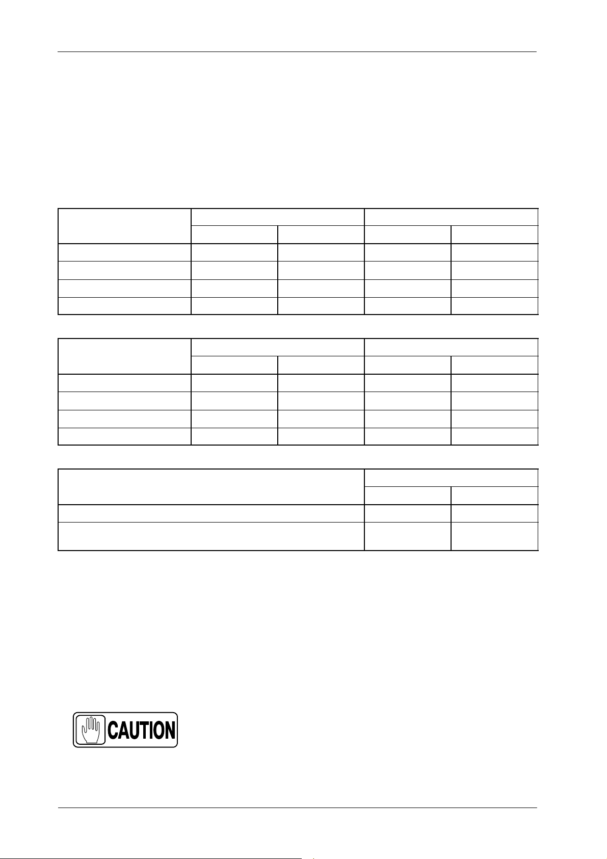
5. Configure the Filament Times by setting the dip switches 3000SW2-4
through 3000SW2-8 per Table 2-3. The Filament Setting Time should be
configured in accordance to Rotor Acceleration Time of the X-ray Tube.
Table 2-3
High Speed: Configuration of Filament Time
FILAMENT SETTING TIME
TUBE-1
0.8 seconds
1.2 seconds
1.8 seconds
2.7 seconds
TUBE-2
FILAMENT SETTING TIME
0.8 seconds
1.2 seconds
1.8 seconds
2.7 seconds
FLUORO FILAMENT HOLD-OVER TIME
3000SW2-7 3000SW2-8
OPEN (OFF) CLOSED (ON) OPEN (OFF) CLOSED (ON)
- -
- -
- -
- -
3000SW2-5 3000SW2-6
OPEN (OFF) CLOSED (ON) OPEN (OFF) CLOSED (ON)
- -
- -
- -
- -
3000SW2-4
OPEN (OFF) CLOSED (ON)
After releasing the Fluoro Pedal, the Filament Current goes back to stand-by.
After releasing the Fluoro Pedal, 1 minutes passes
before the Filament Current goes back to stand-by.
Note .
The Filament Setting Time is factory set to 1.8 seconds. Maintain
this value when it is unknown or not provided with the X-ray Tube
documentation.
Record switch configuration in the Data Book.
6. To validate previous configuration, turn the Generator ON, wait until
Error--01 (E01) appears on the Console and turn the Generator OFF.
Set dip switch 3000SW2 to the original settings as recorded
in step-1. (Refer to Section 1.1.5 for the normal settings of Dip
Switch 3000SW2).
-
-
24
CF-1004R4
Page 29

2.4 LIMIT OF MAXIMUM kW
The Maximum kW of the Generator is factory set according to the Generator
performance. Generator kW can be limited to a lower value.
HF Series Generators
Configuration
Note .
Note .
This limit can be set to a lower value to match the maximum
Generator power to the Line power, due to a high line impedance
(refer to Pre-installation document).
1. Enter calibration mode.
2. Select the E07 Memory Location (memory location is shown on the mA
Display).
3. Set the new limit of Maximum kW by pressing the “+1”or“-- 1 ” (or
“Increase” and “Decrease”) density push-buttons until the correct
number is showed in the kV Display.
4. Store the new value by pressing the “AEC Reset” push-button.
5. Exit from calibration mode.
Record configuration data for E07 in the Data Book.
CF-1004R4
25
Page 30

HF Series Generators
Configuration
This page intentionally left blank.
26
CF-1004R4
Page 31
SECTION 3 FILAMENT AND ANODE TESTS
3.1 FILAMENT DRIVER
Make sure the Generator is OFF.
Verifythat Test dip switch 3000SW2-2 (Filament and Rotor interlock bypass) on
the H T Controller Board is in the “Off” position.
Turn the Console ON and verify that both LEDs (DS1 and DS2) on the Filament
Driver Board are ON.
3.2 FOCAL SPOTS CONFIGURATION AND TEST
HF Series Generators
Configuration
Determine the mA station where switch-over from Small to Large Focal Spot will
take place. The smallest mA station for the Large Focal Spot can be any of the
available mA station or E01 memory location when is required to configure all
mA stations for the Small Focal Spot. This mA station is selected according to
the Tube rating and/or customer preference.
IF THE mA STATION FOR FOCAL SPOT CHANGE IS NOT
CONFIGURED ACCORDING TO THE X-RAY TUBE RATINGS,
THE TUBE FILAMENTS CAN BE PERMANENTLY DAMAGED.
1. With the Generator OFF, set dip switch 3024SW2-3 on the ATP Console
CPU Board in “On” position to permit the service mode.
2. Power ON the Console and enter in calibration mode.
3. Select the smallest mA for the Large Focal Spot by using the “mA
Increase / Decrease” push-buttons.
4. Store the selected mA station by pressing the “Power On” and “AEC
Reset” push-buttons on the Console. This stores the switch-over point for
the focal spot selection. When it is confirmed, the ATP Console CPU
Board emits a “double-beep”.
CF-1004R4
If the focal spot switch-over point is changed after mA
calibration, the mA stations affected must be re-calibrated.
27
Page 32
HF Series Generators
Configuration
5. Exit from calibration mode and perform the following test.
Note .
The test described only applies to RAD Tubes.
In case of a R&F Tube (Tube-2) both filament are always ON
(lighted). Select a “Direct” workstation and a mA station for the
Small Filament. Press “Prep” for RAD and observe through the
X-ray Tube window that the Small Filament lights more than the
Large Filament.
6. Select the highest mA station for the Small Focal Spot. Verify that
effectively the Small Filament is ON (lighted) and the Large Filament is
OFF. Observe filaments through the X-ray Tube window.
7. Select the lowest mA station for the Large Focal Spot. Verify that
effectively the Large Filament is ON (lighted) and the Small Filament is
OFF. Observe filaments through the X-ray Tube window.
8. If required for the second Tube, repeat this procedure.
3.3 ANODE ROTATION TEST
Note .
Perform the following tests for each X-ray Tube in the installation, checking the
low and high speed when it is required.
Two people are needed for these tests, one at the Console and the
service engineer looking at the anode of the X-ray Tube. These
tests also can be done by hearing the sound of the anode rotating.
NEVER MAKE EXPOSURES DURING THE TESTS, THE
PERSON CLOSE TO THE X-RAY TUBE WILL BE EXPOSED.
1. With the Generator OFF, set dip switch 3024SW2-3 on the ATP Console
CPU Board in “Off” position (application mode), turn the Console ON and
select the corresponding X-ray Tube.
2. Press the “Prep” push-button and visually check that the Tube anode
rotates in the proper way. (Refer to the X-ray Tube documentation).
28
CF-1004R4
Page 33

HF Series Generators
Configuration
3. Hold pressed the “Prep” push-button and check that the r otation speed
of the Tube anode is in compliance with the X-ray Tube specifications
(check the low and high speed when it is required).
For this test is recommended to turn off the Tube filaments (switch
3000SW2-2 on the HT Controller in “On” position) and use a stroboscope
to measure the anode speed.
Note .
In service mode (switch 3024SW2-3 in “On”), if the Focal Spot
indicator is blinking it means the Generator is operating in High
Speed. To select High Speed increase the kV, mA and/or
Exposure Time values.
4. Release the “Prep” push-button and visually check that the Tube anode
brakes.
5. If required for the second Tube, repeat this procedure.
CF-1004R4
29
Page 34

HF Series Generators
Configuration
This page intentionally left blank.
30
CF-1004R4
Page 35
SECTION 4 X-RAY TUBE DATA
TUB
E
TUBECOD
E
FOCAL
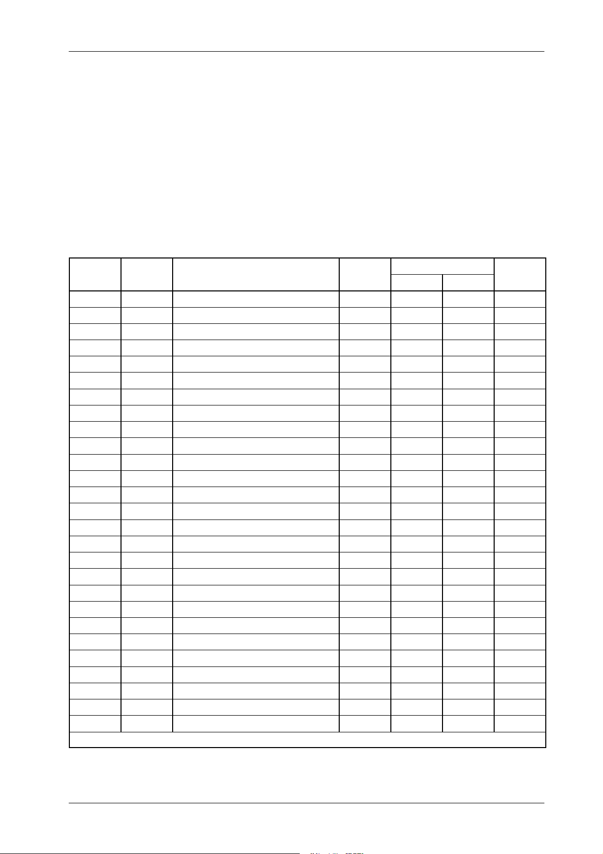
The following table lists several common X-ray tubes and their corresponding
number. If a specific tube is not listed, tube specifications are given to enable
you chose a similar tube type. If none of the listedtubes are satisfactory, contact
your generator supplier to obtain special software.
Table 4-1
X-ray Tube Numbers
HF Series Generators
Configuration
TUBE TUBE CODE
NUMBER
001 139 TOSHIBA E7239X 1.0 / 2.0 22 / 45 -- 133
002 201 TOSHIBA E7240X 0.6 / 1.2 15 / 30 -- 140
003 140 TOSHIBA E7242X 0.6 / 1.5 18 / 49 -- 187
004 090 TOSHIBA E7252X 0.6 / 1.2 15 / 42 26 / 73 300
005 377 TOSHIBA E7254FX 0.6 / 1.2 25 / 66 39 / 100 400
006 274 TOSHIBA E7255FX 0.6 / 1.2 23 / 60 39 / 101 300
007 310 TOSHIBA E7843X 0.6 / 1.2 22 / 49 -- 150
008 344 TOSHIBA E7865X 0.3 / 1.0 3/40 -- 140
009 351 TOSHIBA E7100X 0.6 / 1.2 24 / 59 40 / 100 300
010 260 IAE RTM 101 HS 0.6 / 1.2 22 / 55 37 / 99 400
011 273 IAE RTM 101 HS 0.6 / 1.5 24 / 76 40 / 136 400
012 233 VARIAN RAD 8 1.0 / 2.0 25 / 47 -- 150
013 244 VARIAN RAD 14 0.6 / 1.2 16 / 44 27 / 72 300
014 161 VARIAN RAD 21 0.6 / 1.2 21 / 64 36 / 100 300
015 265 VARIAN RAD 60 0.6 / 1.2 26 / 67 39 / 100 400
016 238 VARIAN RAD 74 0.6 / 1.5 20 / 52 -- 200
017 252 VARIAN RAD 92 0.6 / 1.2 26 / 62 40 / 99 600
018 092 VARIAN A-192 0.6 / 1.2 25 / 63 40 / 96 300
019 309 VARIAN A196 0.6 / 1.0 20 / 47 32 / 72 350
020 094 VARIAN A-292 0.6 / 1.2 25 / 62 39 / 96 400
021 208 VARIAN G 292 0.6 / 1.2 25 / 63 39 / 95 600
022 051 GE-CGR MN 640 1.0 / 1.8 23 / 46 -- 150
023 064 GE MAXIRAY-75 0.6 / 1.5 12 / 37 21 / 62 300
024 062 GE MAXIRAY-100 0.6 / 1.25 18 / 55 31 / 100 350
025 261 SIEMENS DR 154/30/50 1.2 / 1.8 31 / 53 -- 200
026
027
Note .-- Power Ratings are for 60 Hz. To calculate Power Ratings for 50 Hz multiply the values by 0.91 TB47
(ID)
MODEL
FOCAL
SPOT
POWER RATINGS
LS (kW) HS (kW)
KHU
Page 36

HF Series Generators
Configuration
This page intentionally left blank.
32
CF-1004R4
 Loading...