

Page 1
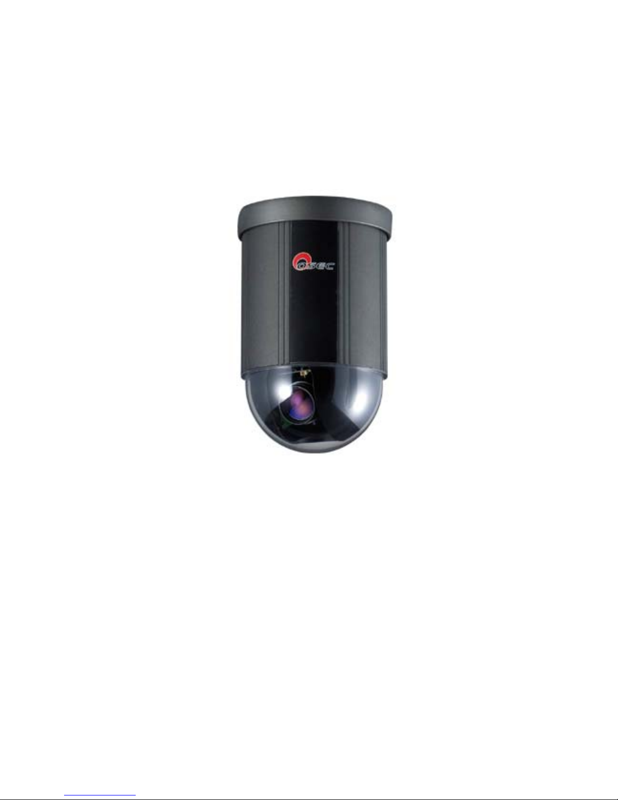
OSE-801 IP Speed Dome Camera
Quick Installation Guide
Product: OSE-801 IP Speed Dome Camera
Document: Quick Installation Guide
Published: March 28, 2007
Version: 1.10
Web: http://www.oosec.com
Service Email: [email protected]
Copyright © 2006 TWSAFE Corp., All rights reserved.
Page 2

Table of Contents
Preface...........................................................................................................................3
Product..........................................................................................................................3
Product Features Overview.................................................................................3
What is Quick Installation Guide (QIG) ...........................................................4
Product & Accessories .........................................................................................4
Hardware Wires & Indicator..............................................................................5
Additional Accessories for System......................................................................6
Mount The Camera......................................................................................................7
Start Installation........................................................................................................11
Install Software ..........................................................................................................12
Start CD Software Installation .................................................................................12
IP Addr ess Setup ........................................................................................................17
Network Security Setup.............................................................................................19
IE Login ......................................................................................................................22
Login Authentication.........................................................................................22
IE .................................................................................................................................24
IE Main Page......................................................................................................24
【Setup】...........................................................................................................28
【Network】......................................................................................................30
【User】 ............................................................................................................31
【Event】 ..........................................................................................................34
【Event】 ..........................................................................................................35
【Email】 ..........................................................................................................35
【Log】..............................................................................................................36
IP Installer..................................................................................................................37
Appendix A DDNS Service........................................................................................41
Appendix B Intellectual Property Right..................................................................49
Appendix C Limited Warranty.................................................................................50
Appendix D PAL/NTSC Country/Region List..................................................51
Page 3

Preface
Congratulations for the purchasing of the world’s most compact IP speed dome
camera. This IP speed dome camera is designed and manufactured not just to meet the
requirements for modern remote digital surveillance, but also increase the systems’
overall performance.
This camera line incorporates high resolution color CCD with ICR function. The
CCD can be set up for automatic switching to black-white mode for night-vision
ready when illumination is low. The pan-tilt mechanism provides controllable
panning (360o) and tilting (90o) functions, giving users the capability to manipulate
the camera for precise locating on target. The built-in micro-controller allows users to
program up to 32 presets for quick and accurate capture to specific view positions.
Moving speed, ranging from 0.25 to 300 degrees per second and is selectable to
controller, is variable in optional levels. Dwell time of each view position is also
selectable in seconds. Also, this camera is equipped with 2-way audio which offers
user not only can monitor the videos but also audio receiving and broadcasting
capability.
System function includes I/O for alarm function for intrusion management. This
device is driven by DC12V power. It can be controlled on web IE, PC, or
multi-camera management software we attach to you in the package.
This camera is designed to be water-resistant for iutdoor use, under the condition of
normal temperature range from 0 o to 50o C. A companion outdoor housing is also
available for severe weather condition (extreme low or high temperature
environment).
Product
Product Features Overview
Compact Size of 4-1/2” (114 mm) diameter
High resolution color CCD 480 TV lines
23 times optical zoom
Continuous panning for 360
o
; Tilt for 180o
Fast rotation speed up to 300
o
per second
BNC connector for video output
Programmable for view position, speed and dwell
View position preset up to 32 points
Auto-pan and preset locations cruise
Page 4
2 alarm inputs and 1 alarm output
12V DC
Water resistant design
Be able for embedded, surface, wall and ceiling mount
External housing for severe outdoor environment (Option)
MPEG4 web server module
Two-way audio communication
What is Quick Installation Guide (QIG)
The purpose of this QIG is to guide you how to setup this system in order to view
remote video images of video server on IE. As for details of setup functions on IE
and management software, user’s manual has more details to discuss.
Product & Accessories
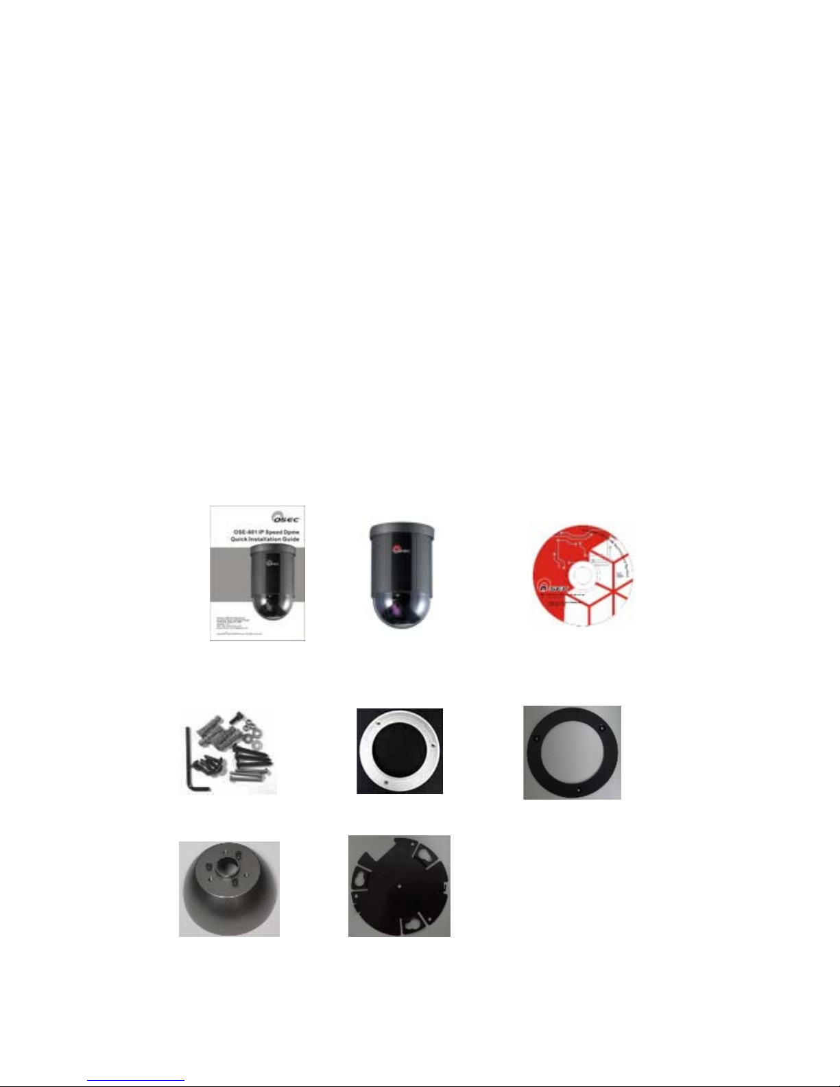
Please check packing contents thoroughly while opening this pack. Please
contact your reseller while item is missing.
Quick Installation Guide
OSE-801*1
Accessories
Plastic Ring*1
Metal Ring*1
Software CD
ROM*1
Mounting base
Metal bowl
holder
Page 5
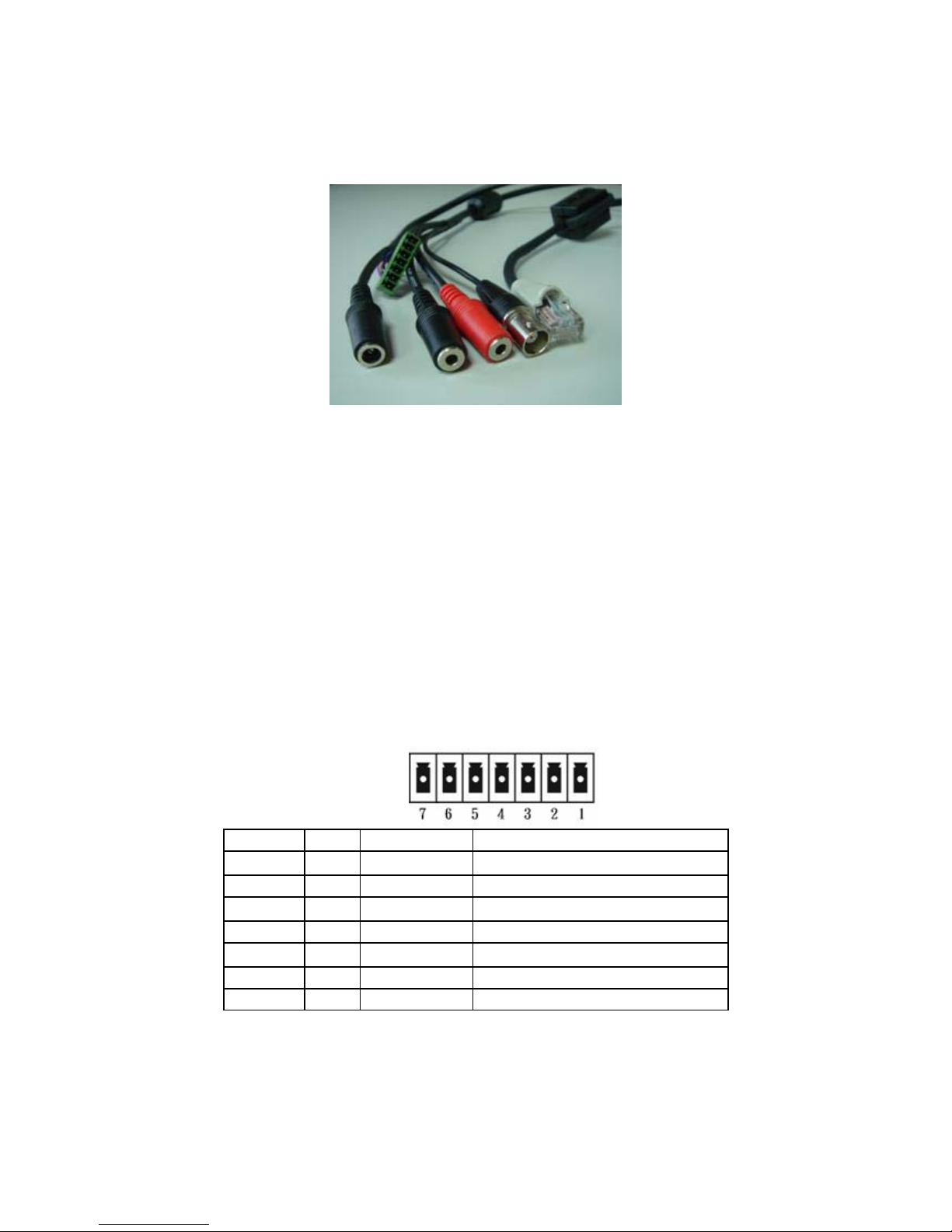
Hardware Wires & Indicator
1. Audio: Black: Microphone input ; Red: Speaker
2. Video Output: BNC bypass analog video to connect TV or monitor.
3. RJ-45: 10/100 Mbps auto detection to connect networking device such as switch/hub, IP
sharing, or router.
4. Power indicator: Plug-in power will auto light on
5. Reset Button: Use L-type wrench and press this button for 5 seconds to restore
manufacture’s default values.
6. Power: plug-in standard DC-12V
7. I/O: Product offers 2 digital inputs and one digital output to integrate other security
devices.
Port. Function Remark
1 Black DI1+ DI-1 positive
Max.50mA,12VDC
2 Brown DI1- DI-1 negative
3 Red DI2+ DI-2 positive
Max. 50mA,12VDC
4 Orange DI2- DI-2 negative
5 Purple DO DO positive
Max 3A,125VAC / 30VDC
6 Grey DO DO negative
7 Blue COM TX/RX Non-inverting
Page 6
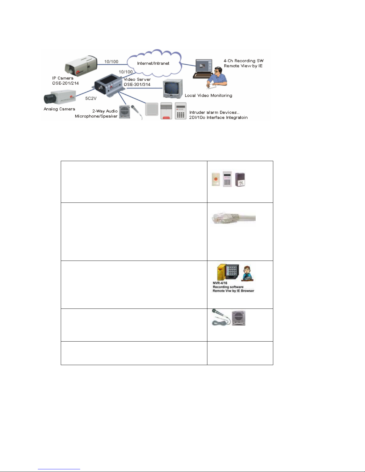
System Reference Structure
Additional Accessories for System
y Alarm/Access control: DI/DO to connect
urgent button, sensor, buzzer, system for
security integration.
Alarm (option)
y UTP cables: Prepare a parallel UTP cable with
RJ45 connectors to connect network
equipment e.g. switch/hub, IP sharing, router.
Use a cross-over cable if directly connects to
PC.
RJ45 UTP cable
y Recording Software Requirement: CPU Intel
P4 3.0, 1G memory, 128 MB VGA, OS:
Microsoft XP SP1
y IE View: Pentium Celeron 1.7G
Personal computer
y Audio: Microphone and speaker
Microphone/speaker
(option)
y Bandwidth: XDSL broadband for Internet
connection
Page 7
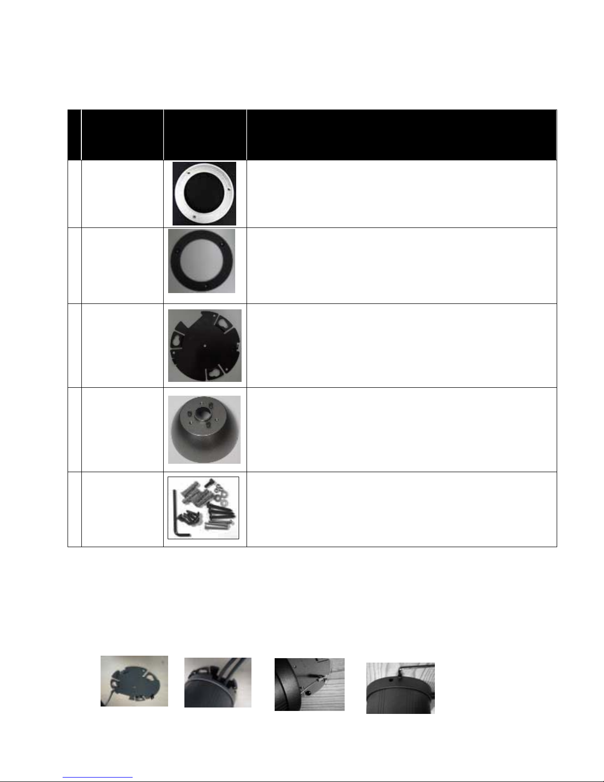
Mount The Camera
Mounting Accessory
Description Photo Use
1
Plastic ring
To hold the camera embedded on ceiling
Must be used with the metal ring together to hold the speed dome camera..
2
Metal ring
To hold the camera embedded on ceiling
Must be used with the plastic decoration ring together to hold the speed dome
camera.
3
Mounting base
a To hold the camera on ceiling surface
b Used together with item # 4 (bowl type holder) for ceiling hold or wall mount
4
Metal bowl
holder
To work with item 3 for creating ceiling or wall mount
5
Screw pack
Screws for the build of camera’s holding structure
Surface mount onto Ceiling
Locate the base onto the place the camera is to mount, and fix the base on the place tightly with screws
through the 3 holes on the base (be sure screws are complete in the ceiling)
Get the camera and secure it to the base with the supplied metal chain.
Then fit the camera body to the base, rotate the camera body clockwise until it is completely locked
into position.
Put the screw A (anti-loss) in position and screw it in
Page 8
In case of dealing with a concrete wall:
a. Mark the locations for screw through the holes on the base
b. Make holes on the wall, then insert the supplied plastic plugs into the
holes and squeeze them in until they are flush with the wall surface.
c. Mount the base on the desired place tightly with screws
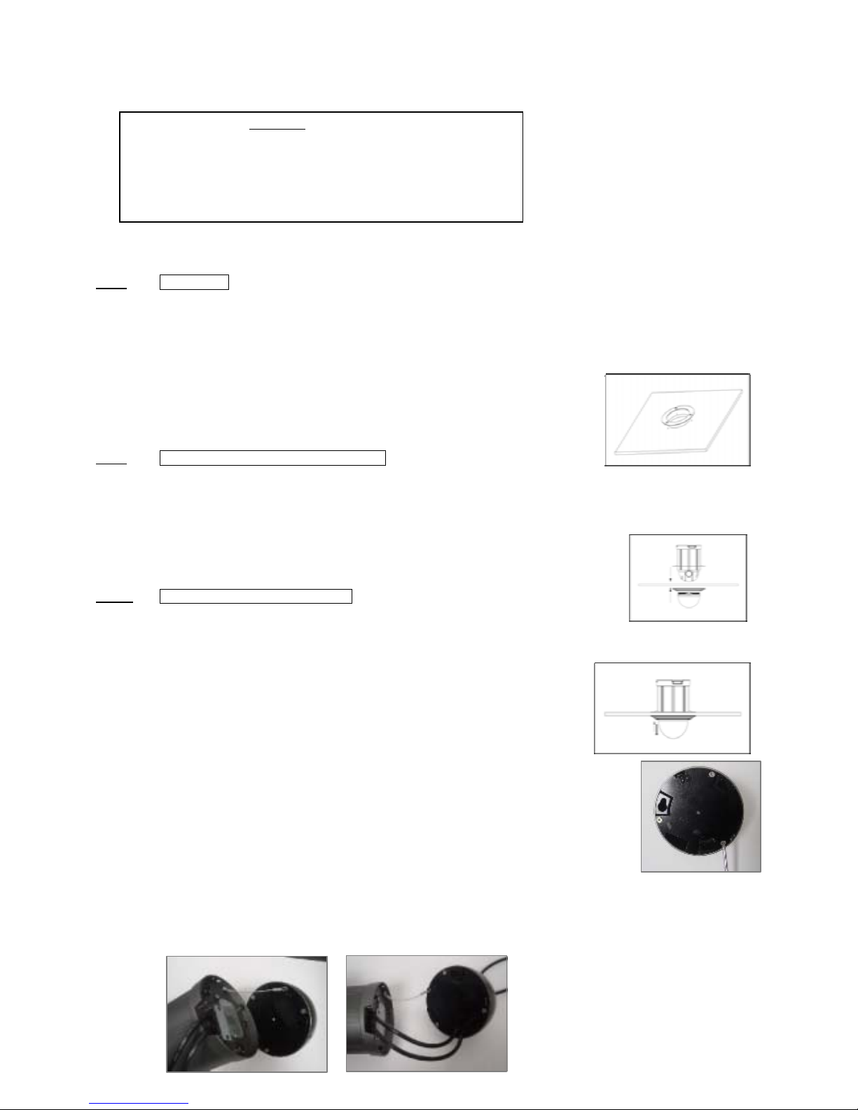
Embed The Camera Into Ceiling
Step 1 make holes
To insert the speed dome into the ceiling, first a hole must be properly made to let the dome be through for hanging.
The best way to decide the diameter of the hole and the spots for mounting screws is to use the supplied metal holder.
Put the holder on the surface of the target location and mark a circle with pencil or color
marker
Also mark out the spots for screws with the screw holes on the holder
Cut the camera hole alone with the curve
Drill holes for screw in 6 mm (1/4”) on the three marked spots;
Step 2 Integrate the decoration ring with camera
The decoration ring is not just for nice looking, but also the piece to hold the camera in place for
embedded mounting.
To integrate the ring to camera:
1. Take the transparent dome cover off
2. Locate the ring to the bottom side of the cover
3. Put the cover back to the camera
Step 3 Mount the camera through the hole
Take the below steps to make the camera cling to ceiling:
1. Place the auxiliary metal bracket onto the top of the ceiling
2. Put the camera through out the hole
3. Align the screw holes of the decoration ring and the auxiliary bracket
4. Put screws through and tighten the two brackets, with the ceiling in between
Wall-mounting
The mounting procedure
Step 1
Get the metal bowl and mounting base, put them together with screws to make them a
sub-assembly for mounting.
Step 2
Hook the sub-assembly and camera with the safety cable located on the bottom of camera (left picture on below), then put the signal
cables throughout the sub-assembly
(right picture).
Page 9
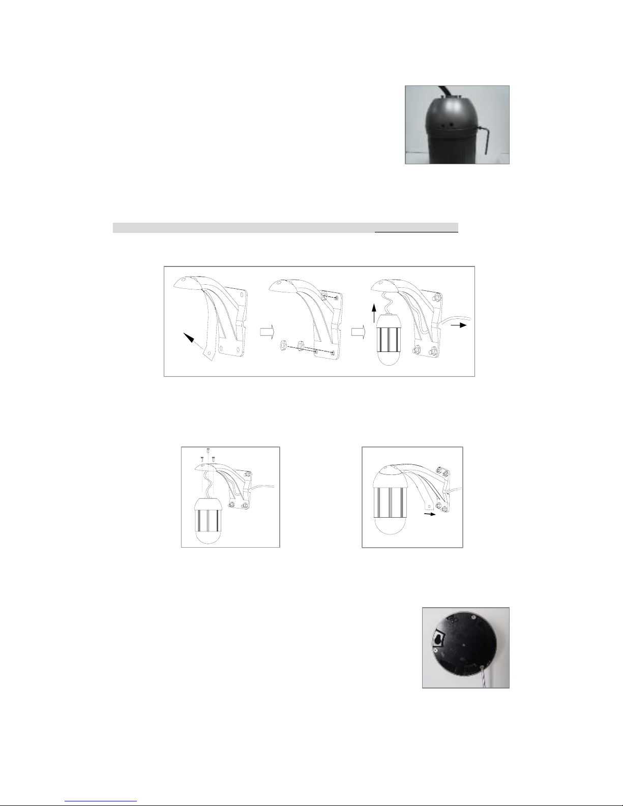
Step 3
Fasten the sub-assembly and camera together at the joint of D-sub connectors.
Rotate camera all the way in direction of clockwise.
Fix the base to camera with the supplied screw and wrench.
Step 4 Get the wall-mount bracket. Remove the metal cover (sheet) from the bracket(Fig-1)
Step 5 Mount the bracket onto wall (Fig-2) but DO NOT tight the bracket to wall completely until the Step 6 and 7 are finished.
Caution: Be sure the wall is strong enough to hold the entire device (i.e. housing + camera)
Step 6 Lay all the signal cables in the trench of bracket, and have all connectors come out bracket through the cable outlet (Fig-3).
Step 7 Fasten the camera module (assembly) to the bracket with supplied screws(Fig-4)
Step 8 Put the cover back to holder(Fig-5)
Ceiling-drop
To mount the camera from ceiling, a metal wall-mount bracket in separate package will be needed.
The mounting procedure
Step 1
Get the metal bowl and mounting base, put them together with screws to make them a
sub-assembly
for mounting.
Fig-1 Fig-2 Fig-3
Fig-4
Fig-5
Page 10
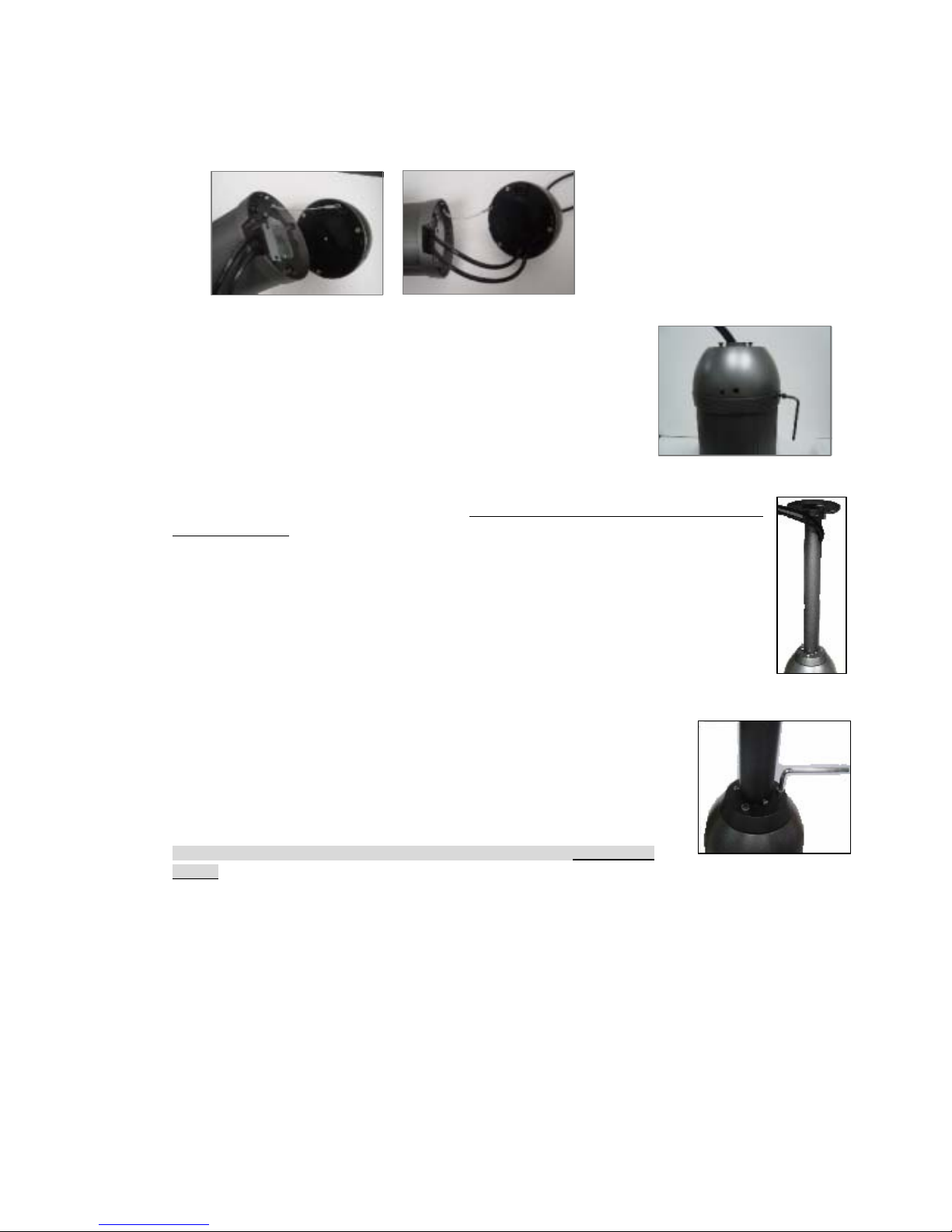
Step 2 Hook the sub-assembly and camera with the safety cable located on the bottom of camera (left picture on below), then put the signal
cables throughout the sub-assembly
(right picture).
Step 3
Fasten the sub-assembly and camera together at the joint of D-sub connectors. Rotate
camera all the way in direction of clockwise. Fix the base to camera with the supplied
screw and wrench.
Step 4
Get the ceiling mount bracket. Put cables into the tube, starting with the 9-pin alarm I/O (take the male part off
to obtain smaller size).
Have all connectors come out the tube from cable outlet near the top of the bracket.
Step 5 Fasten the camera module (sub-assembly) to the bracket with the supplied screws
Step 6 Mount the bracket onto ceiling and tight the bracket completely.
Caution: Be sure the wall is strong enough to hold the entire device (i.e. housing +
camera)
Page 11
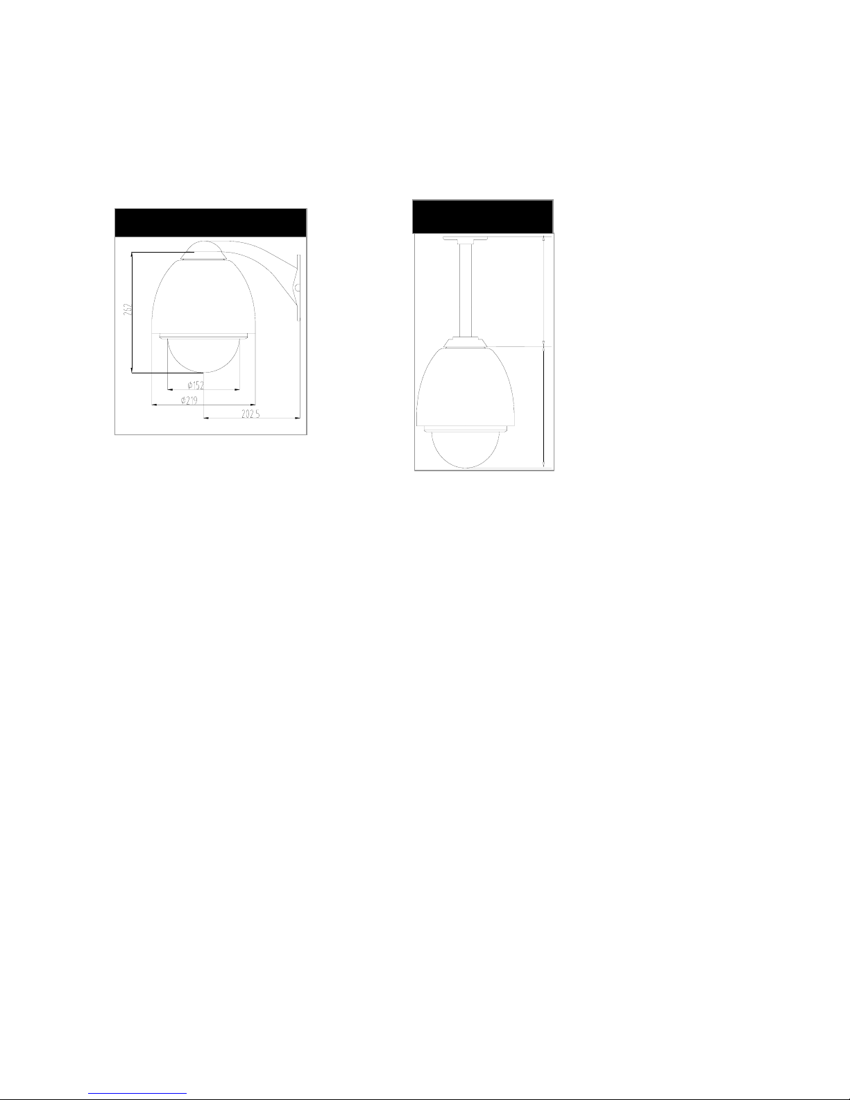
Use External Housing
To operate speed dome camera and maintain all functions in normal in severe temperature conditions, i.e. below -10oC or above 45oC, external
housing is required.
Specially designed for mating each other with ease, this speed dome camera has a companion housing for such extreme outdoor environment, in
options of ceiling and wall mounting configuration, as shown by the pictures on below.
Start Installation
Step 1: Connect Microphone/speaker.
Step 2: Connect security devices into digital inputs/output.
Step 3: Use 5C2V coaxial cable to connect TV/monitor.
Step 4: Use RJ-45 UTP cable to connect network equipment.
Step 5: Plug-in powers of all optional connected devices.
Step 6: Plug-in power of IP speed dome camera.
Step 7: Confirm power indicator is on.
Step 8: Start-up PC to start application software installation.
Wall mount
262 300
Ceiling mount (Option)
Page 12
Install Software
Start CD Software Installation
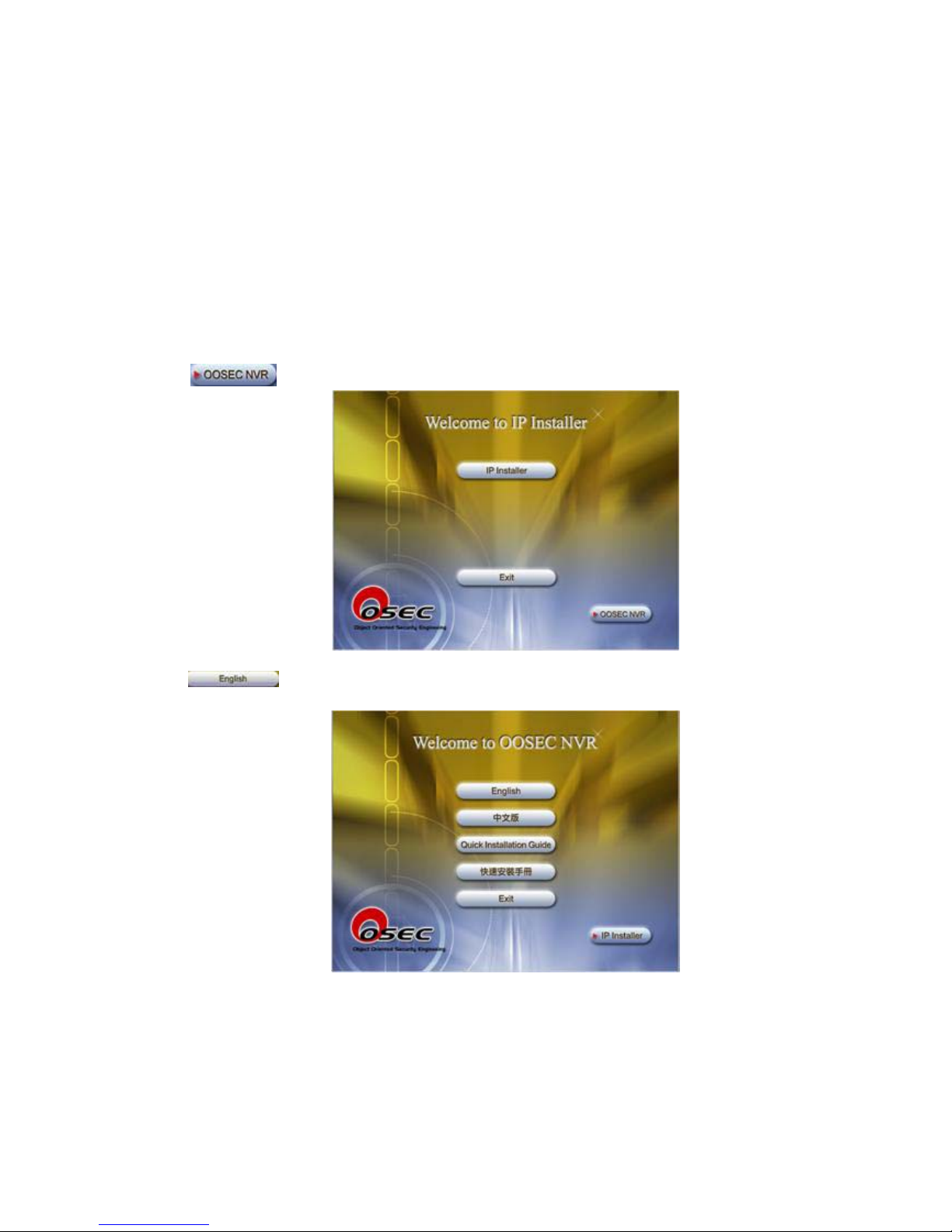
Before Installation: Insert the CD attached in the package to CD-ROM reader in your computer,
system will start its auto-execution procedure.
Software Installation Sequence
Click to enter NVR multi-camera software installation sequence.
Click to enter English Installation sequence.
System is detecting user’s PC, please wait.
Page 13
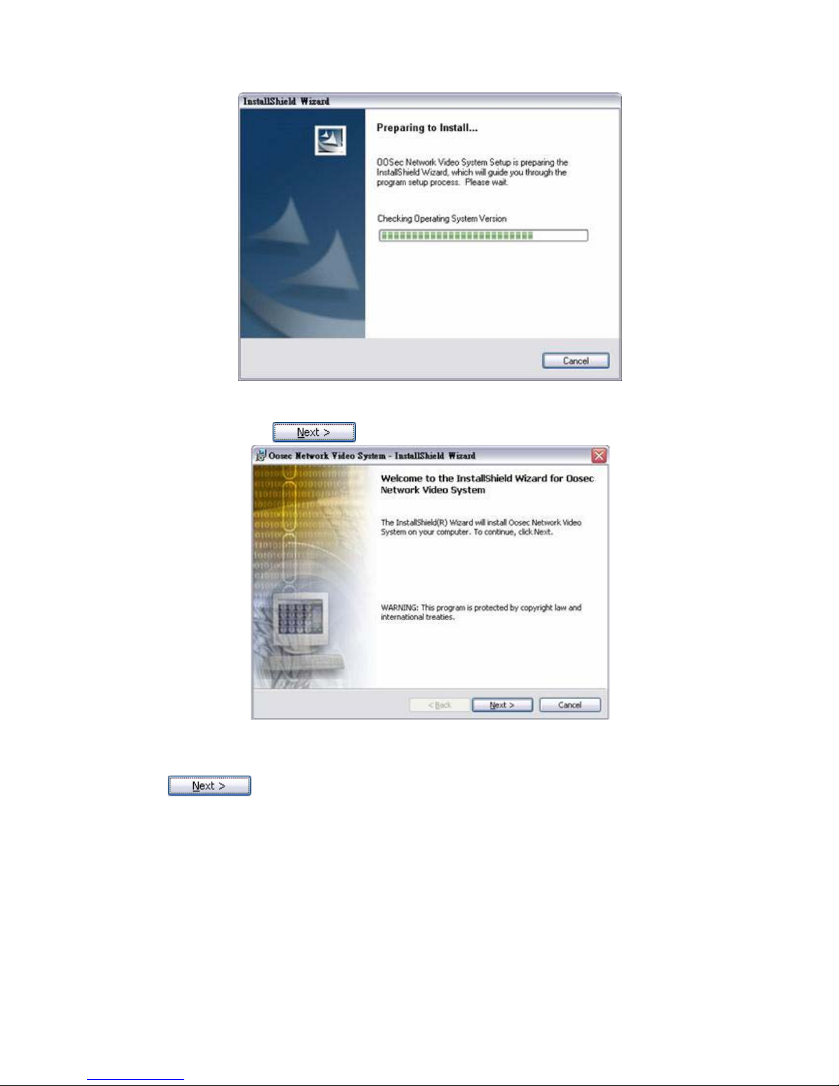
Welcome Page: Click to enter next setup procedure.
Read Me & Intellectual Property Announcement: User needs to click “I accept the terms in the
license agreement” to enter next step of setup procedure or the setup sequence will not proceed.
Click to proceed.
Page 14
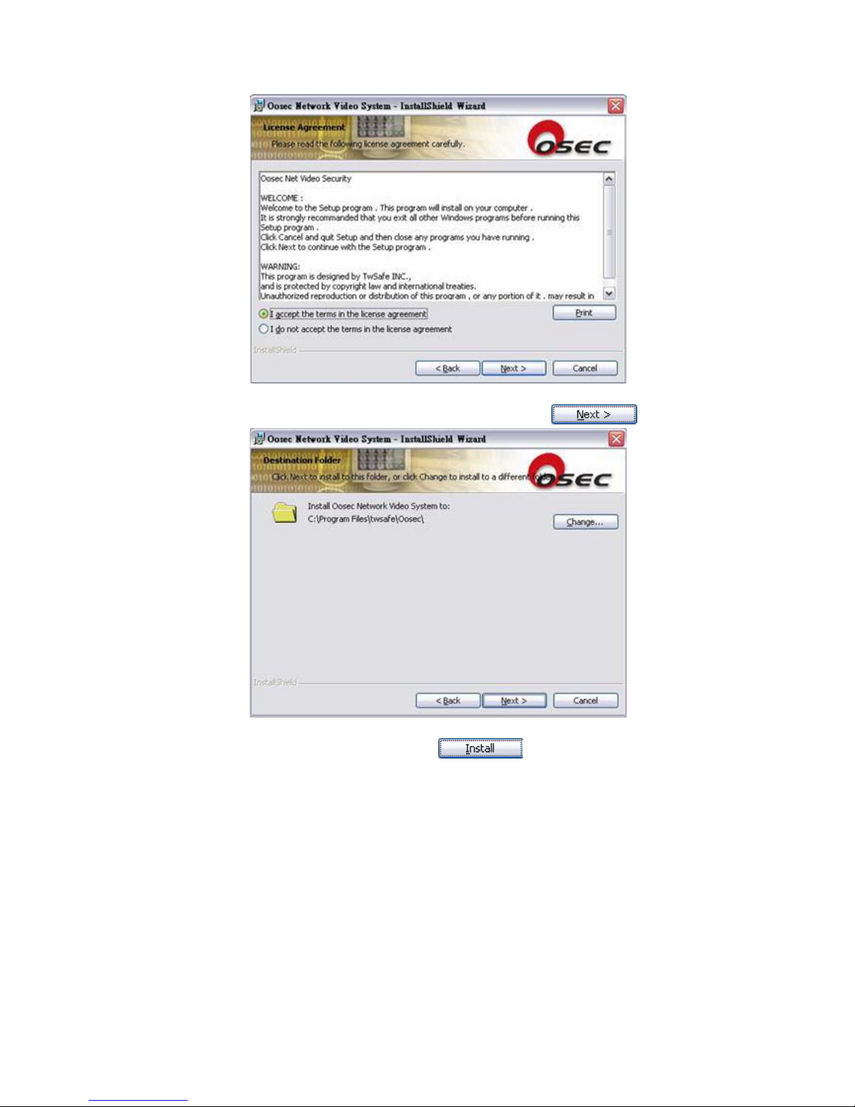
Save-path: User defines save path of the execution file. Click to proceed.
Check: Check setup details are correct. Click to proceed.
Page 15
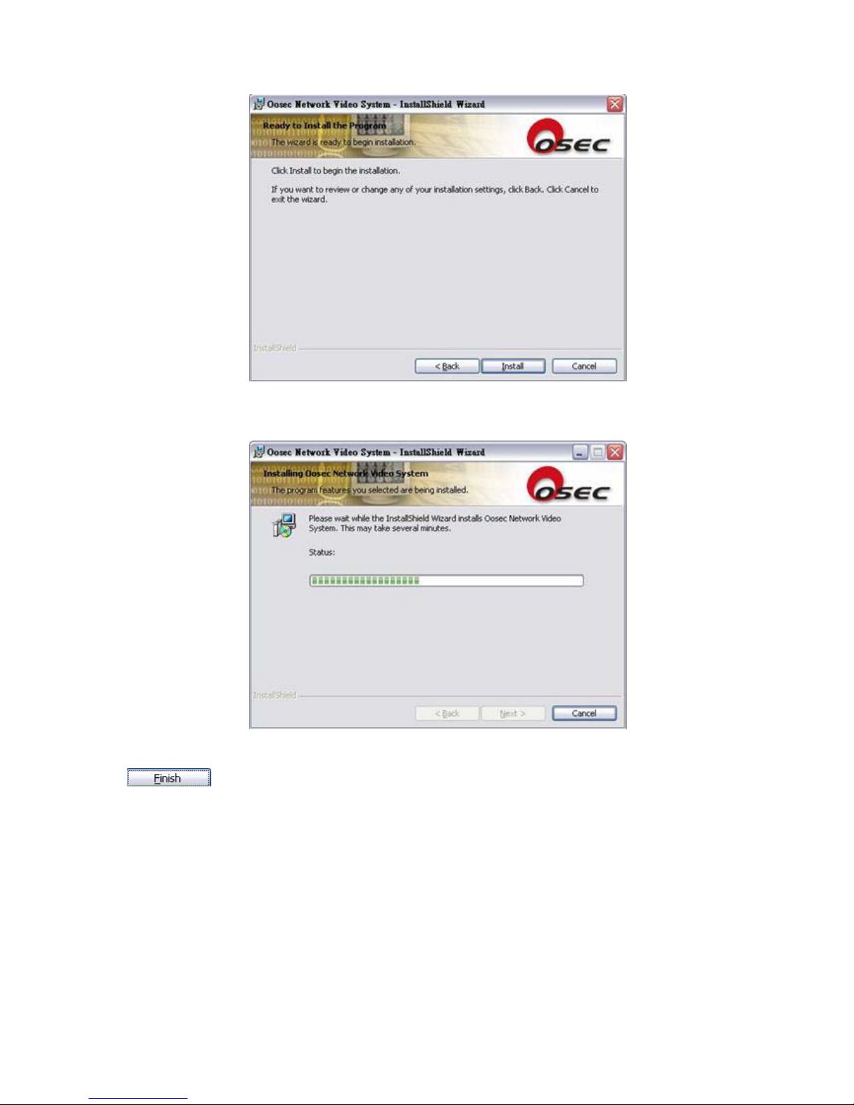
Installing: System setup is proceeding, please wait.
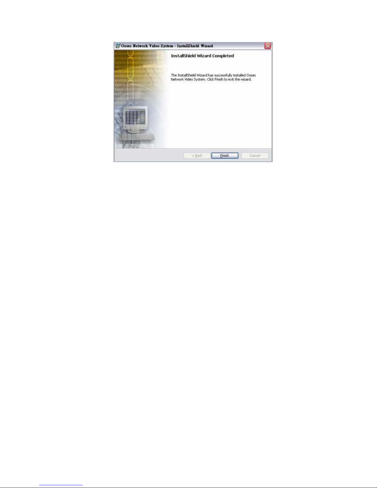
Installation Complete: System installation sequence is complete. Click
to exit.
Page 16
Page 17
IP Address Setup
User can write IP address onto Product either by IE, IP Installer or multi-port application
software.
Remark: 1. Product default IP address is “192.168.1.99” and default password is Mac address
(0013dcXXXXXX) shown on the package and bottom of the camera.
2. User needs to revise PC’s IP at 192.168.1.XXX before setup new IP address on camera
Please follow procedures listed below to change default values on personal computer
Hardware connection
Prepare a crossover UTP cable to connect directly with PC (192.168.1.XXX) or a standard
parallel UTP cable and insert it onto swich/hub or IP sharing (if LAN MASK is same with
product).
Network and Internet Connections
Before IP Installer setup sequence, user needs to adjust Internet Connection.
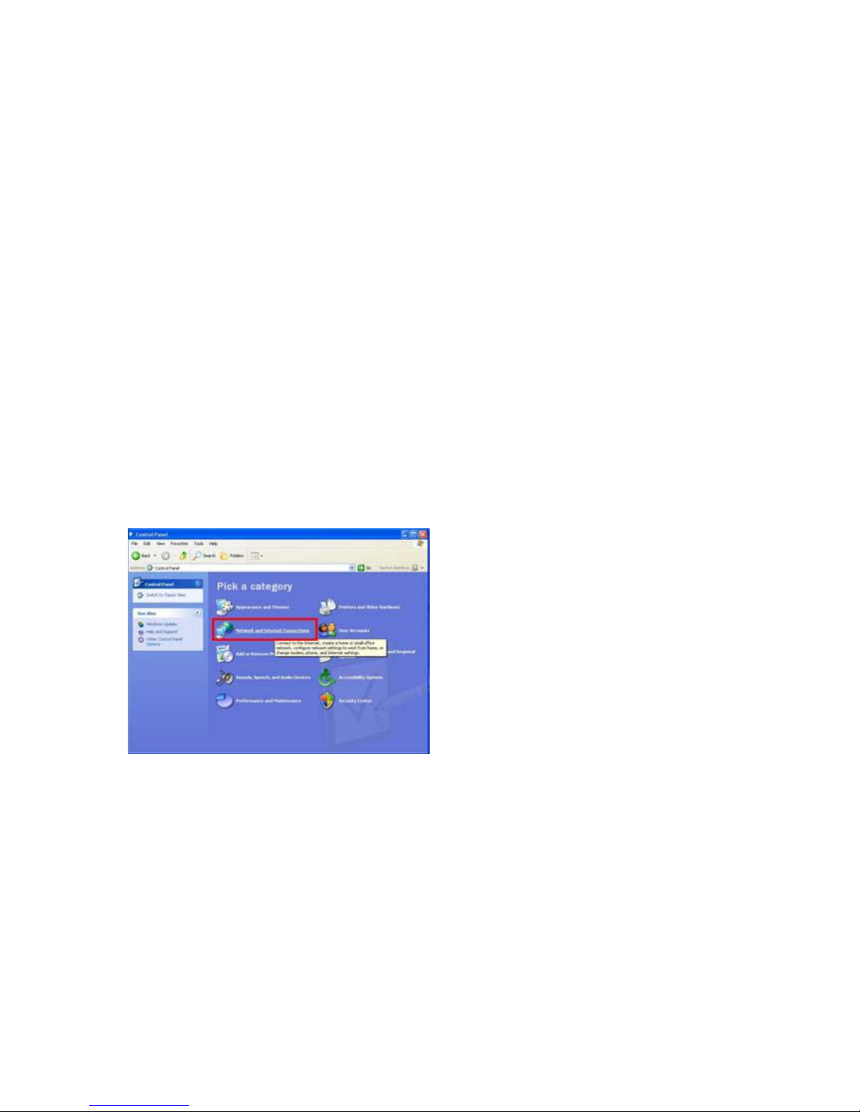
▼ Click “Start”Æ “Control Panel” Æ “Network and Internet Connections”
▼ Click ”Network Connections”
Page 18
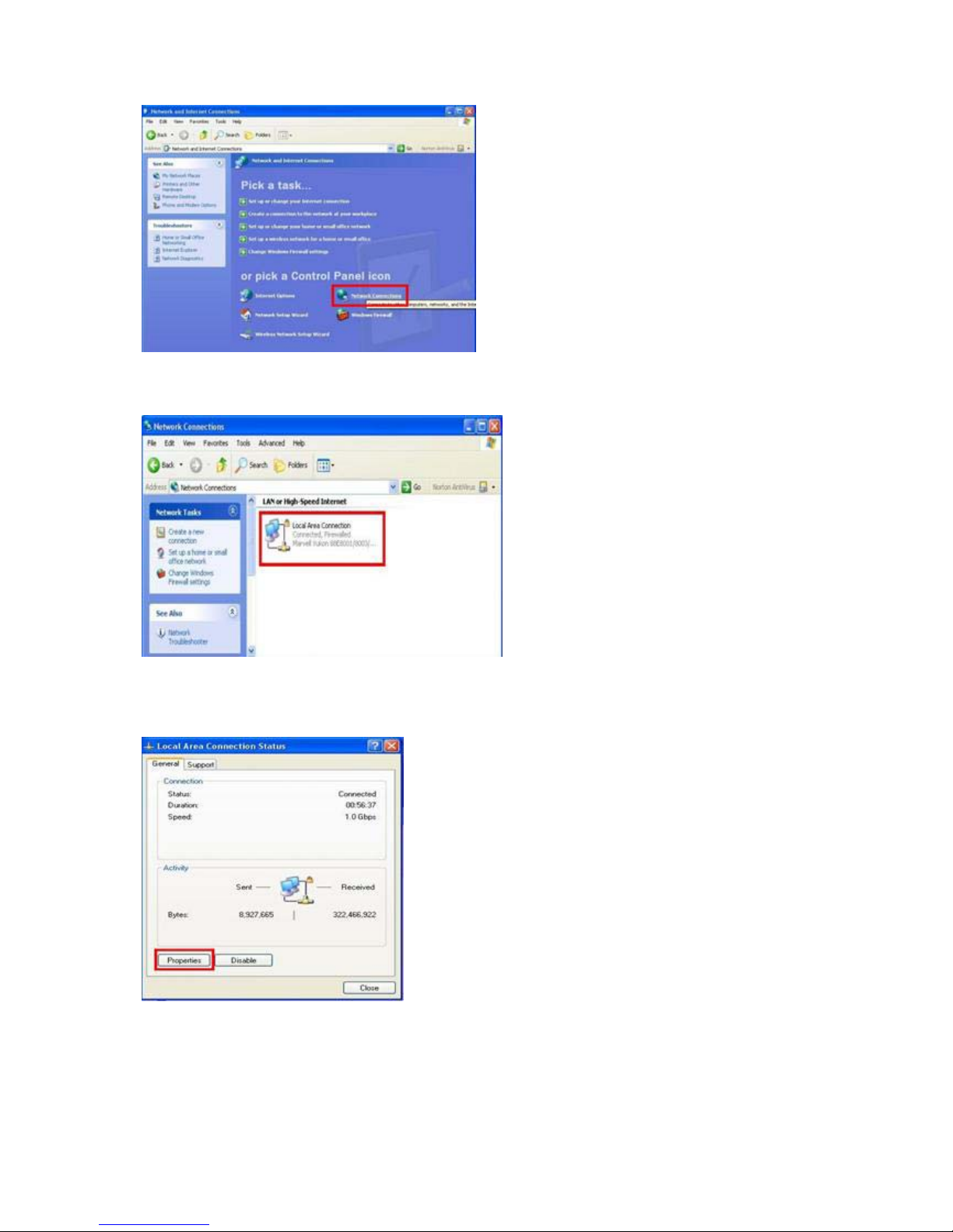
▼ Double click your network (Local Area Connection)
▼ Click “Properties” to enter IP address setup.
▼Double click “Internet Protocol (TCP/IP)
Page 19
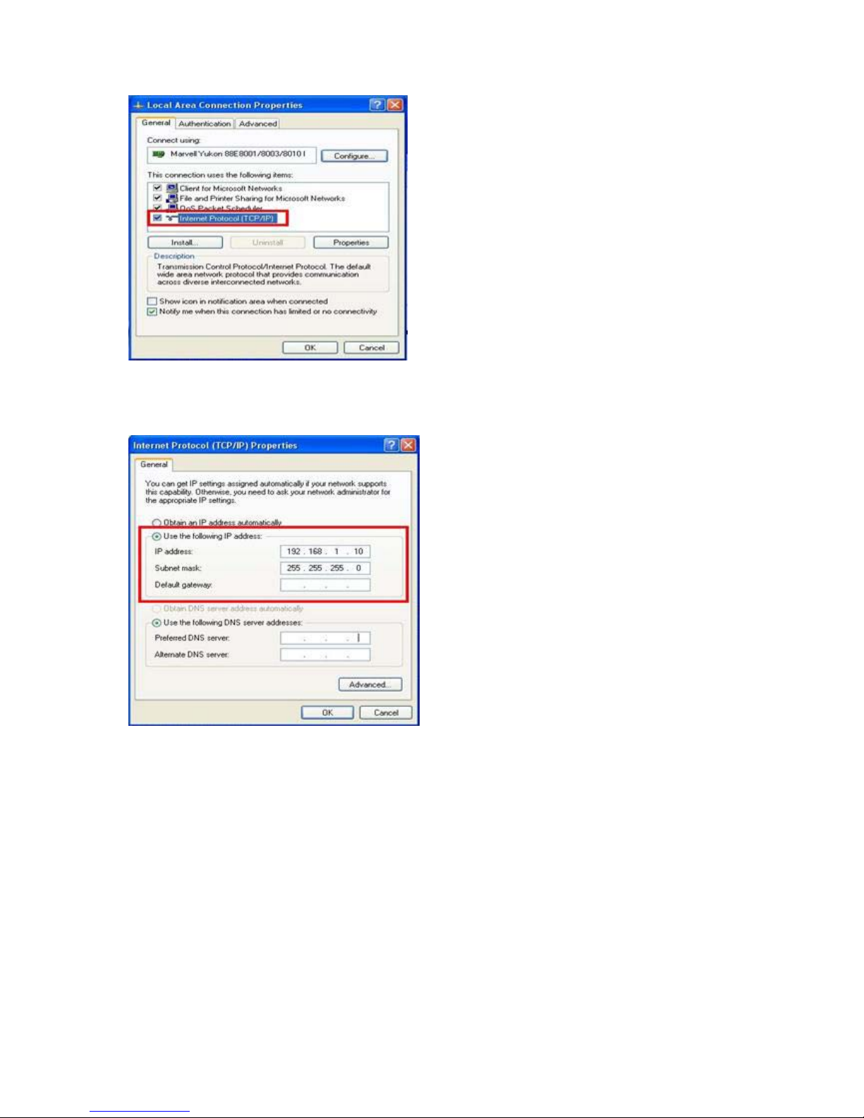
▼Tick “Use the following IP address” then type IP (I):192.168.1.99, and for Subnet mask is
255.255.255.0
Click “OK” icon to finish network connections setup for user’s PC and video server are in the
same subnet. User can setup IE security for remote view.
Network Security Setup
Security/Trusted Sites Setup
When first time to login video server via Internet Explorer, user needs to do security
adjustment to view video images.
Sequence: Click “Start”Æ”Control Panel”Æ”Network and Internet Connections”
Æ”Internet Options” Æ”Security” Æ “Internet” Æ “Custom level”.
Page 20
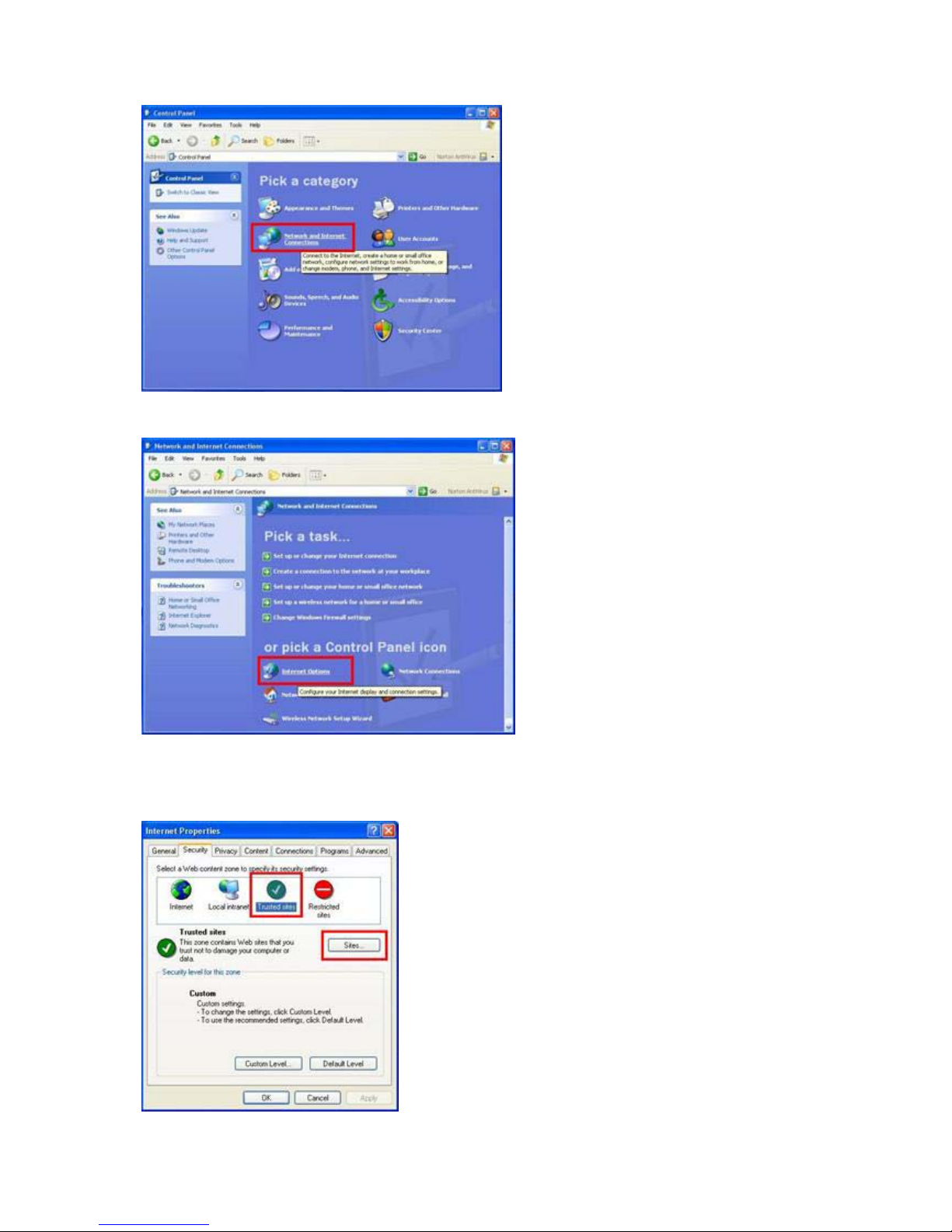
▼ Click “Internet Options”
▼Click “Trusted Sites” and then click “Sites” to type wishful IP address for IP camera/video
server to ensure IE browser will not block the IP address.
Page 21
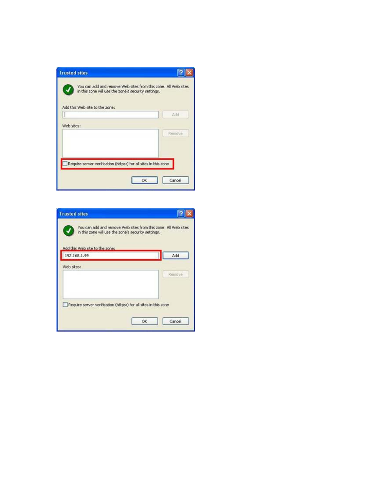
▼ Type wishful IP address for IP camera/video server and DO NOT click “Require server
verification (https) for all sites in this zone.
▼ Window shows IP address is typed.
▼ Type wishful IP address and Web site will show in the window, click “OK” button to save
data.
Page 22
IE Login
User’s PC must be equipped with IE 6.0 or later version.
Login Authentication
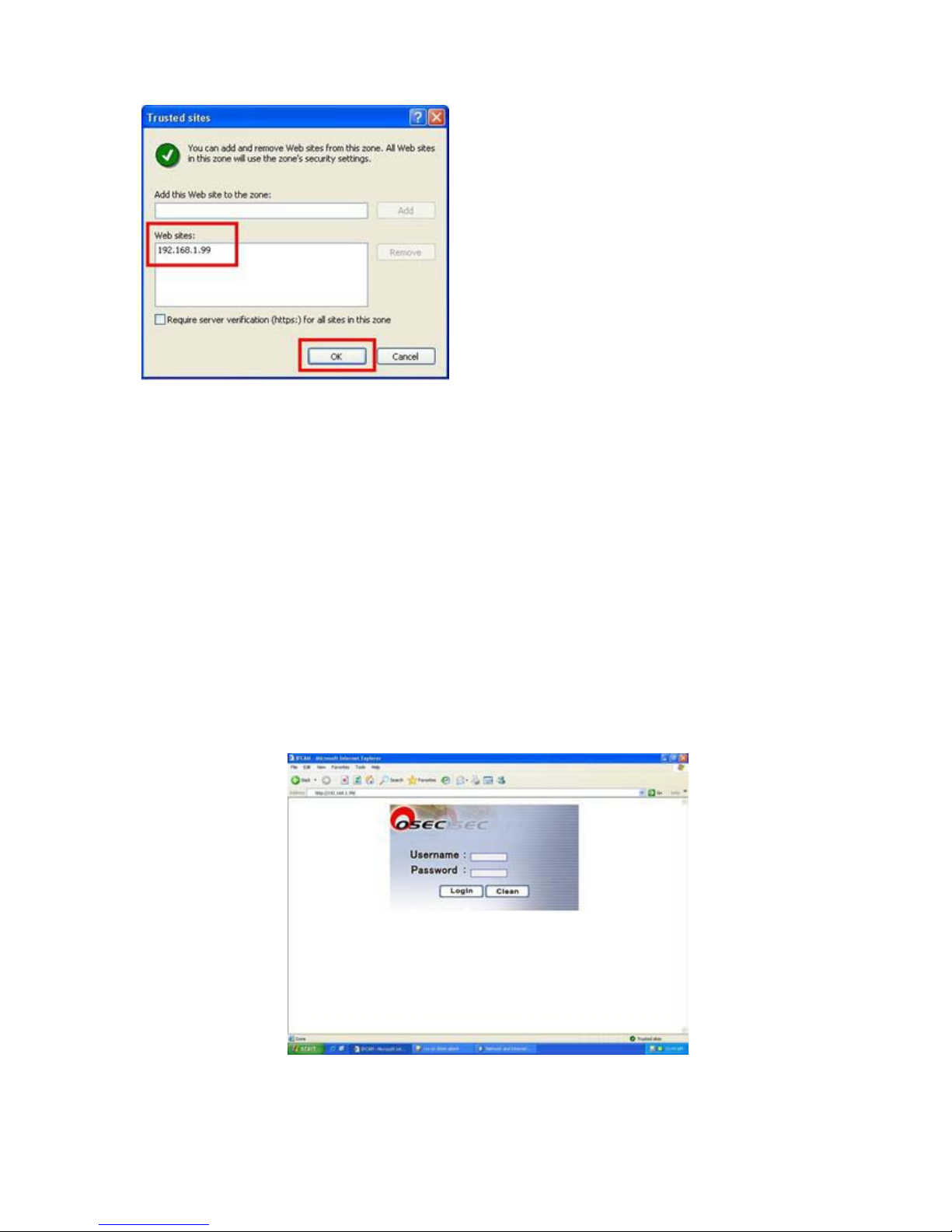
▼ After having typed correct IP address (default: 192.168.1.99), system will pop-up a
verification window which needs user to type correct username and password to login IE
real-time video images.
Remark: Please type “root” for user’s account and MAC address (0013dcXXXXXX) of this
IP camera/video server (MAC is shown on the bottom of product and the surface of the
pack)
Page 23
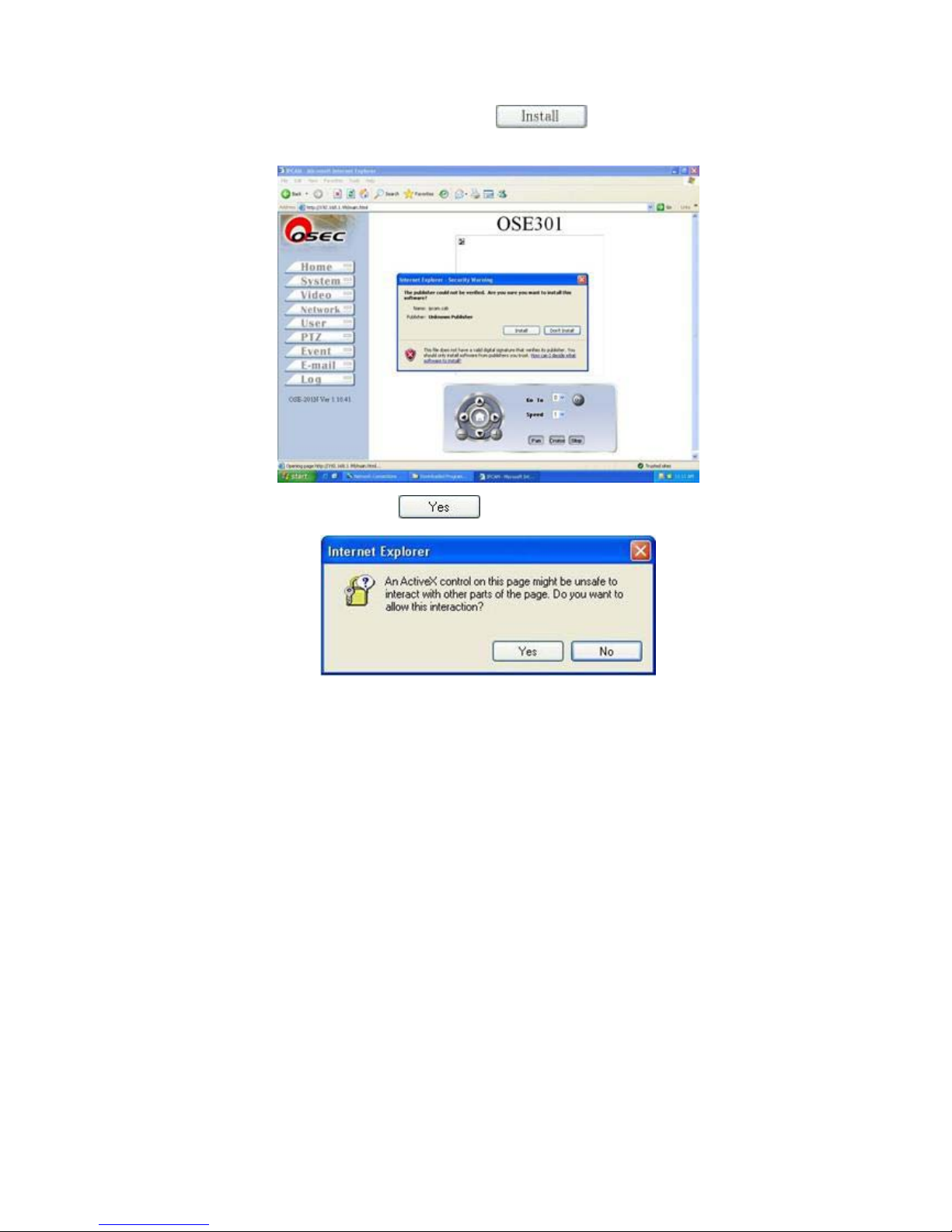
▼ System will ask user to install ActiveX, click to install ActiveX onto PC to view
images. User needs to wait for dialogue window popup patiently.
After downloading ActiveX, click to view real-time images.
Page 24
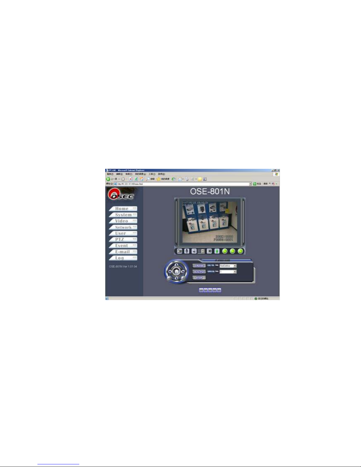
IE
IE Main Page
There are three major blocks on IE main page which include setup icons, real-time video, and
pan-tilt-zoom control panel.
Setup Icons: Web server setup functions of this camera on the left.
Real-time Video: This window includes real-time video images, functions of snapshot,
microphone, speaker, DI indicator, DO, and control buttons.
Pan-tilt-zoom: This section includes pan-tilt-zoom, speed, preset location, and other command
controls.
【Real-time Video Images】
Page 25
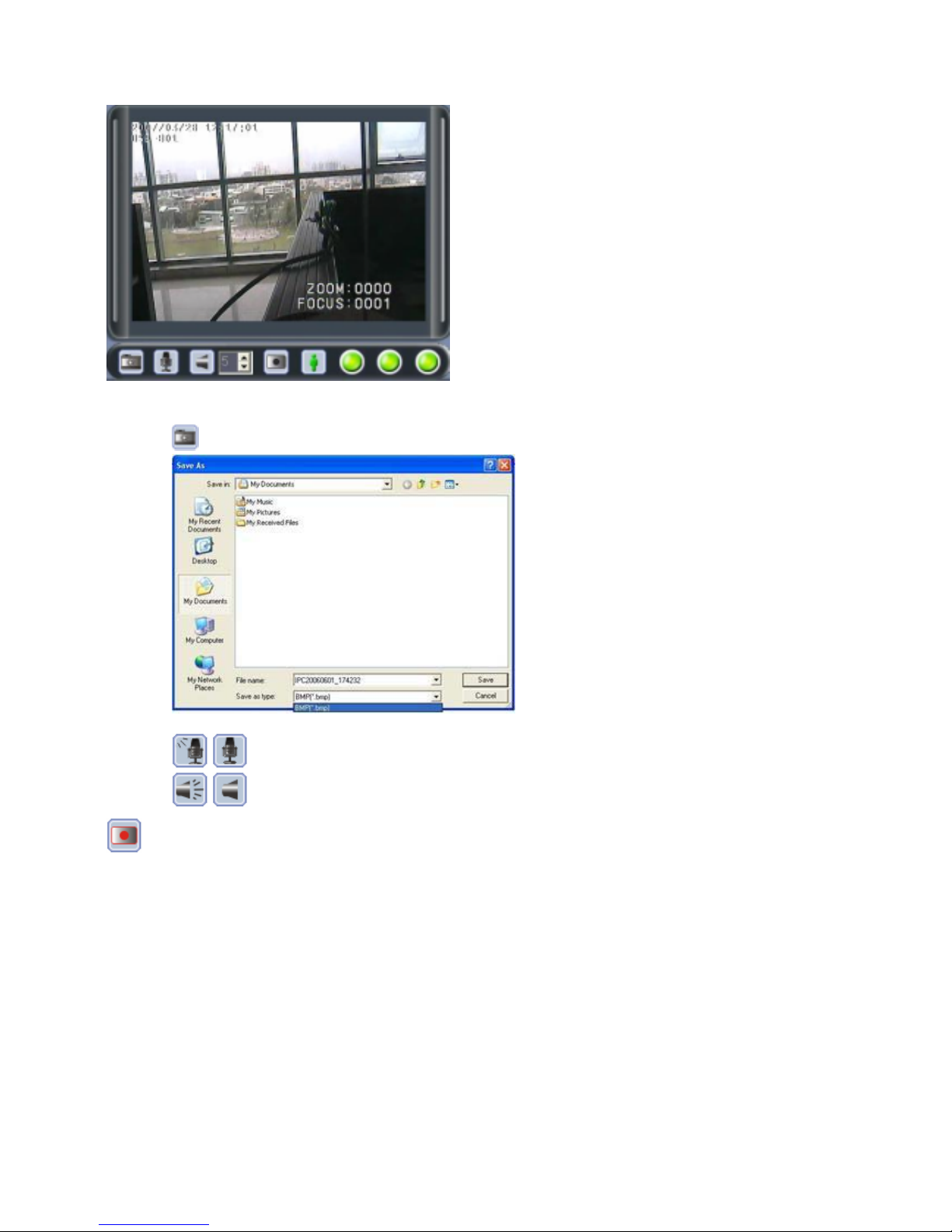
1. System shows real-time videos, and on-screen-display clock.
2. : Click it to save selected picture onto your computer.
3. / : Click to activate or deactivate on-site microphone (default: off).
4. / : Click to activate or deactivate on-site speaker (default: off)..
: Click it to capture real-time video images on your computer. You need to assign wishful save-path
onto your computer. System provides *.AVI file and self recording file format for user to choose.
Page 26
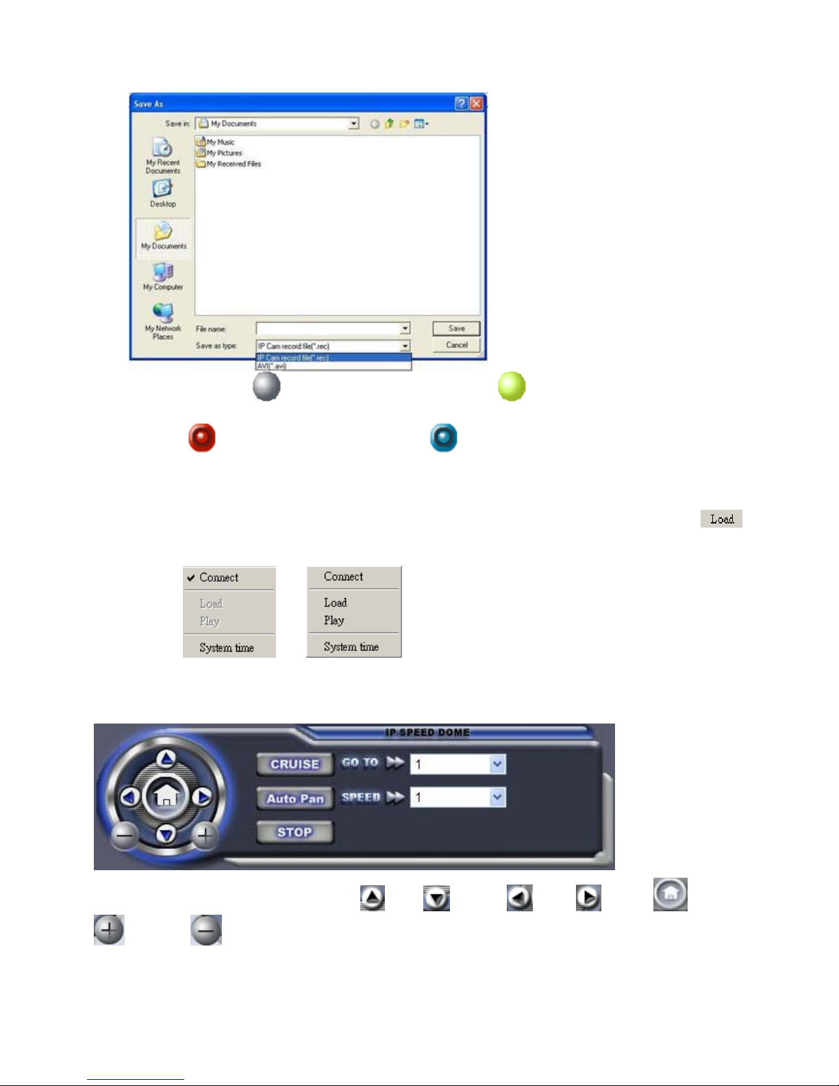
5. DI indicators: indicates no DI message which indicates DI alarm is triggered.
indicates off and indicates message triggered.
6. DO: indicates high-volt output and indicates low-volt output. User clicks DO
button once manually to activate DO alarm and click once to deactivate DO.
7. IE Playback: Move mouse to real-time video on IE and click right key of the mouse, it will
come up with a window, move mouse to connect and click left key once. Real-time display
will be off. Click right key again and system will come up with a window. Click on
left key of the mouse to retrieve recorded data.
【Pan-tilt-zoom Control Panel】
Control direction and zoom in/out: device up/ down/ left/ right/ home/
zoom-in/ /zoom-out
Page 27
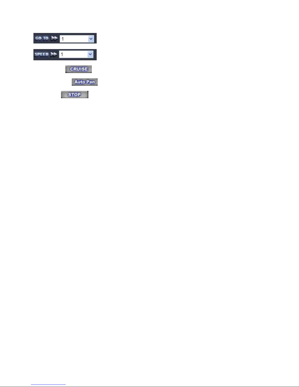
Go to preset location(See details of PTZ setup)
Pan-tilt speed control, 1: the slowest ; 10: the fastest
Curise: Click for preset locations cruise.
Auto Pan: Click for pan curise
Stop: Click to stop “cruise” or “auto pan” function.
Page 28
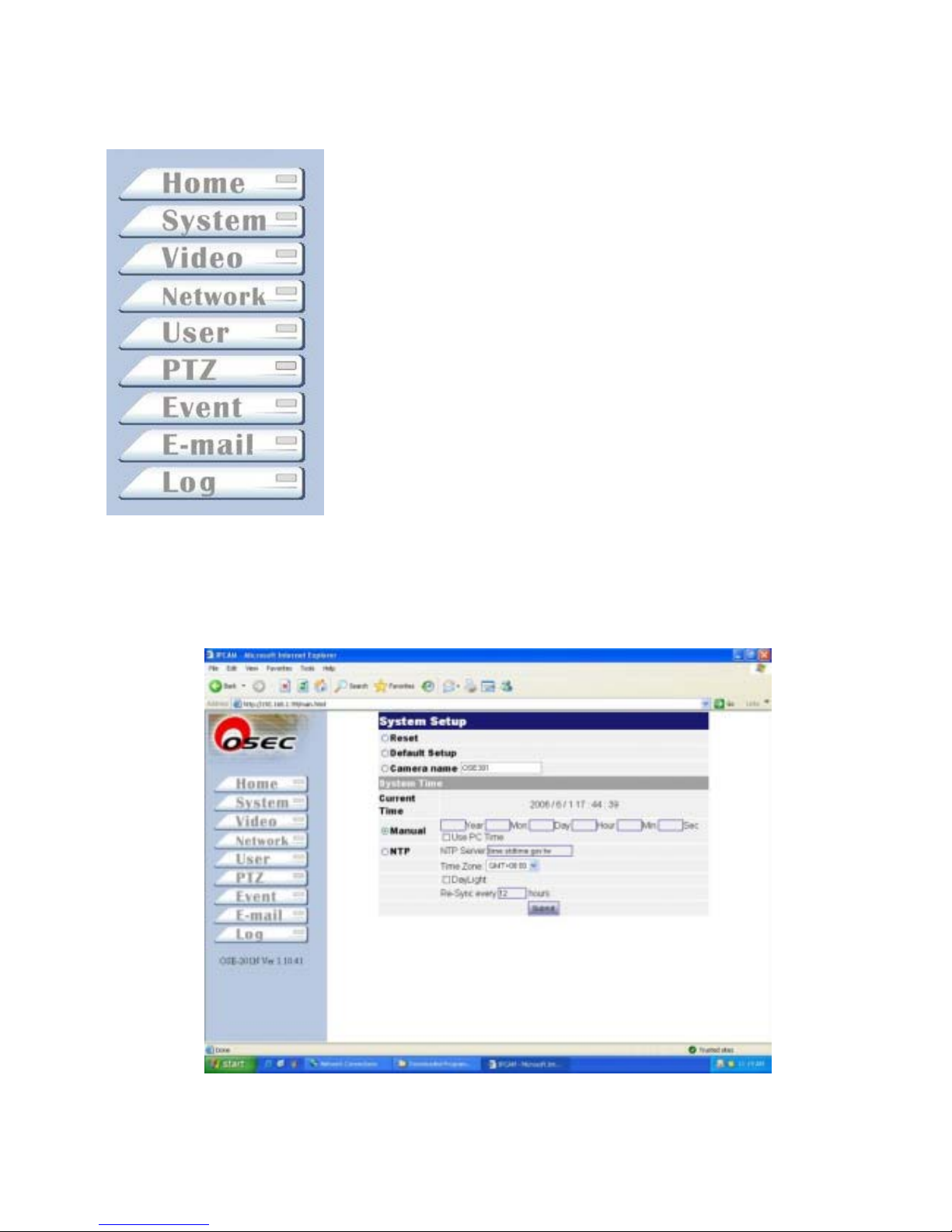
【Setup】
Back to IE main videos
Device system setup
Video function setup
Device network setup
User’s account setup
Pan-tilt-zoom setup
Event triggered setup
Email account setup
Log inquiries
【System】
System time setup, synchronized with NTP, and default values reset.
Page 29
z System Setup
Reset: Click to reboot system.
Default Setup: Click to return to default manufacturer’s values.
Camera Name: Type wishful IE title for this camera
z System Time
Current Time: Display current time of this camera.
Manual: Manually reset wishful time setup.
Use PC Time: Click to synchronize current time with your computer.
NTP : Select your time zone, click to active Day Light, IP of NTP server.
Re-Sync: Time period to synchronize with NTP server.
z Click to save data.
【Video】
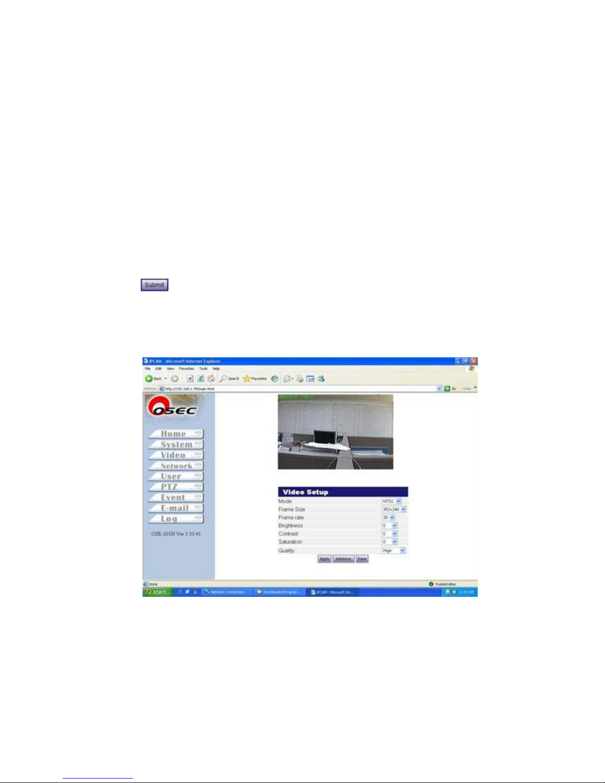
【Mode】: Select NTSC or PAL to fit into your video format in your country (See Appendix D)
【Frame Size】Video resolution setup
NTSC: (QCIF) 176X120, 320X240, and (CIF) 352X240
PAL: (QCIF) 176X144, 320X240, and (CIF) 352X288
【Frame Rate】System support different frame rates for user to define.
Page 30
NTSC: 1,2,3,…..,30
PAL:1,2,3,……,25
【Brightness】Video brightness range from -10 - +10, default: 0
【Contrast】Video contrast range from -10 - +10, default: 0
【Saturation】Video saturation range from -10 - +10, default: 0
【Quality】Video quality range for “High”, “Medium”, and “Low”
Click onto device (not permanently save) and click to save onto device.
Remark: Manufacturer does not recommend user to “Advance” video setup.
【Network】
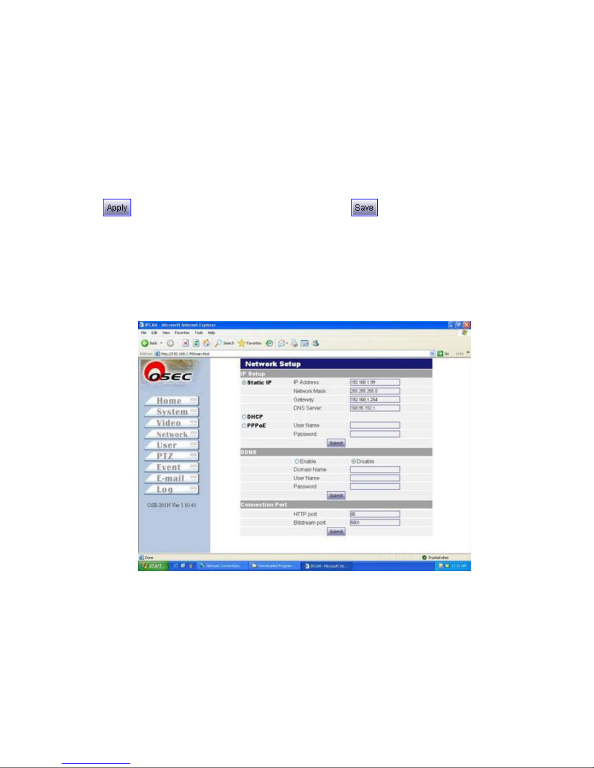
【DHCP】: DHCP assigns IP automatically (See Remark1)
【Static IP】: If you use a fixed IP by ISP provider or for LAN, then input your wishful IP onto device.
Please contact your ISP provider for more details of IP address, Network Mask, Gateway, and DNS
server address.
【PPPoE】: If you’re using PPPoE for Internet connection, input your user account and password
provided by your ISP service company.(See Remark2)
Page 31
【DDNS】: If you’re using domain name instead of fixed IP address and for PPPoE connection, click
“Enable” first, then type domain name, user name, and password to login device.
【Connection Port】
『HTTP Port』: Default HTTP port is 80.
『Bit-stream port』: Default video stream is 5001
Manufacturer does not recommend user to change default value unless has sufficient knowledge of
networking setup. You may contact your MIS or ISP provider for more details of network setup.
z Click and click “Submit” to save data.
Remark 1: DHCP (Dynamic Host Configuration Protocol) allows devices to connect to a
network and be automatically assigned an IP address.
Remark 2: PPPoE(PPP over Ethernet) provides the ability to connect a network of hosts over
a simple bridging access device to a remote Access Concentrator (Server).
Remark 3: DDNS (Dynamic Domain Name Server) is a service that maps Internet domain
names to IP addresses. DDNS serves a similar purpose to DNS: DDNS allows anyone
hosting a Web or FTP server to advertise a public name to prospective users. Unlike
DNS that only works with static IP addresses, DDNS works with dynamic IP addresses,
such as those assigned by an ISP or other DHCP server. DDNS is popular with home
network, who typically receive dynamic, frequently-changing IP addresses from their
service provider. To use DDNS, one simply signs up with a provider and installs network
software on their host to monitor its IP address
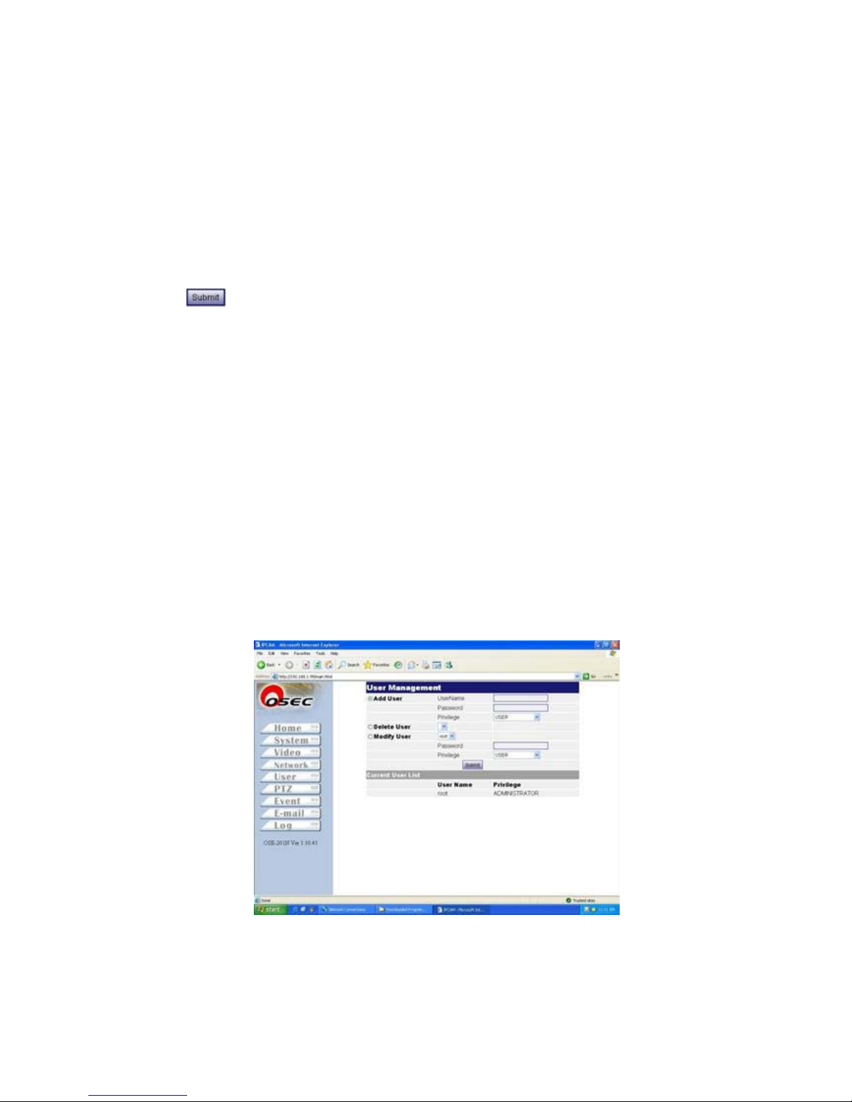
【User】
【User Management】: System allows up to 10 user accounts (2 user privileges) to remote view this
camera.
Page 32
【Add User】: Add new user account, password, and privilege. System supports up to 10 users.
【Modify User】: Modify current user’s account and his/her privilege.
【Delete User】: Delete user’s account.
Click to save onto device.
【Current User List】: Display user account and his/her privilege.
There are two levels of privilege can be setup for the user.
z Administrator: View and setup functions manipulate.
z User:IE browser real-time view only.
【PTZ】
Page 33
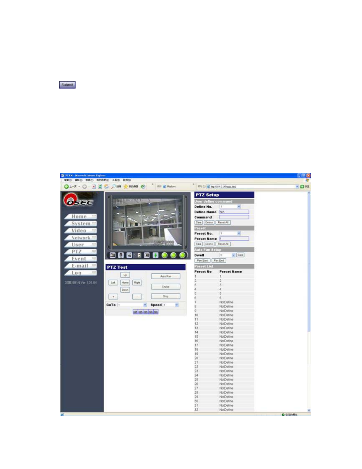
【PTZ Setup】
User define” mode, user needs to setup manually.
z 【User define command】Setup depending upon user’s command requirements.
Define No.(1 - 5): Setup command number
Define Name: Define name of wishful command
Command: Setup command
Click to save data.
z 【Perset】: Preset location setup
Preset No: Camera provides up to 32 locations for user to define.
Preset Name: Give a title for this preset location.
Click to to save data.
z 【Auto Pan Setup】: System provides auto-pan function for camera rotating automatically.
z 【Dwell】: Dwell time for one preset location. System provides 1, 5, 10, and 30 seconds selections.
Click to activate, click to deactivate.
【Preset List】Complete list of whole preset locations
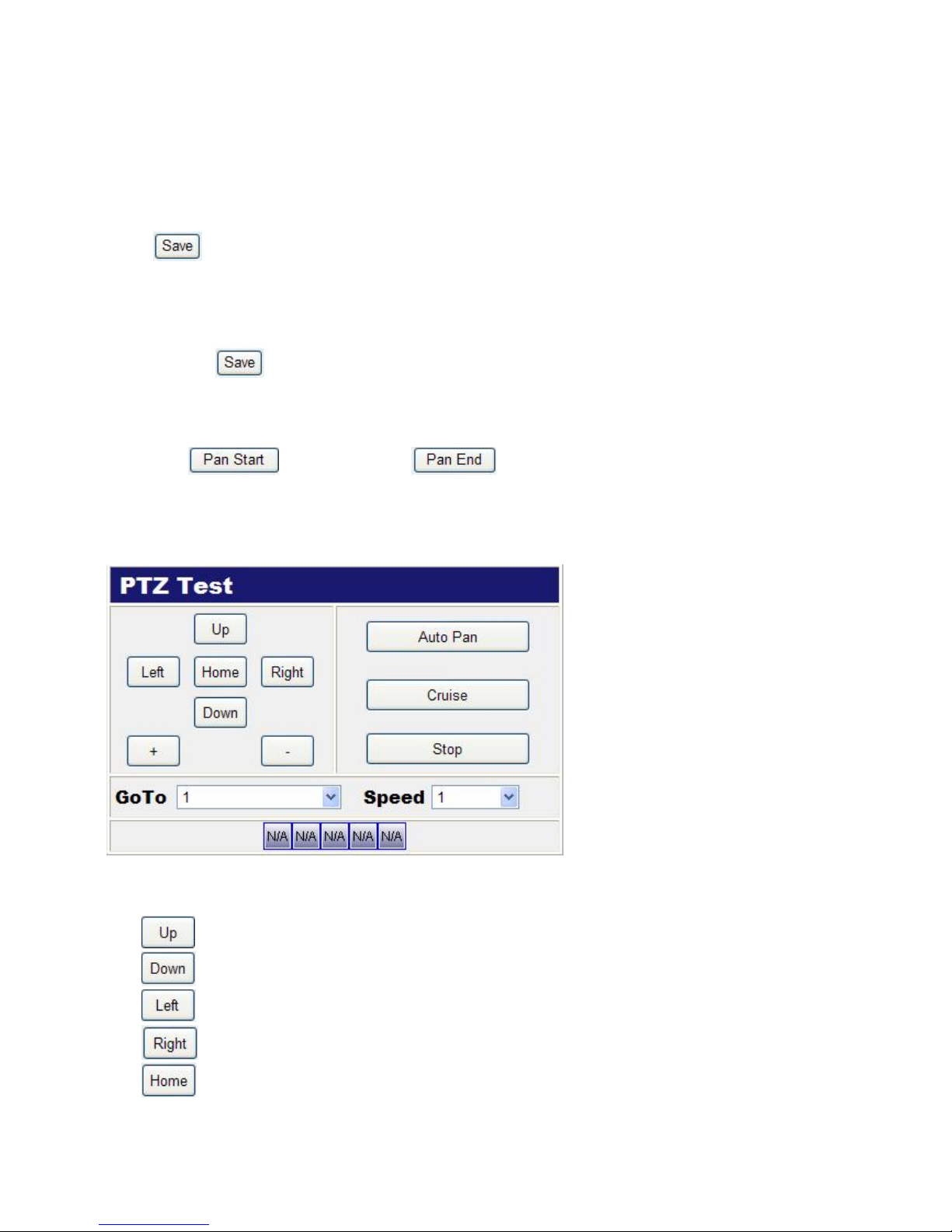
【PTZ Test】: This window is to a test zone to ensure all the control functions are normal.
z This window provides Up, Down, Left, Right, Zoom in, Zoom out, default location, Auto Pan, Cruise,
and Stop.
up
down
left
right
location
Page 34
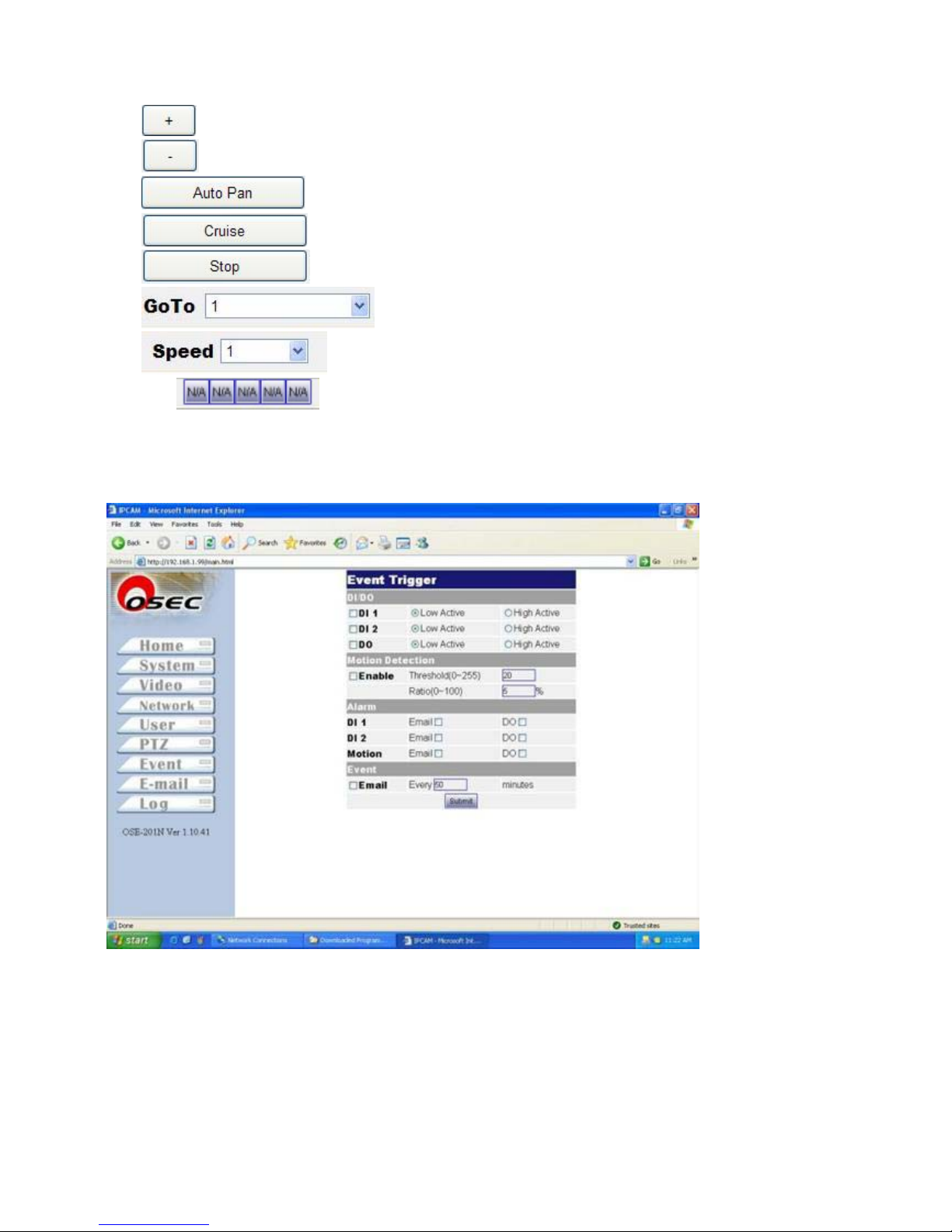
optical zoom-in
optical zoom-out
Auto pan function
Preset locations auto cruise
Stop pan-tilt-zoom function
Click to wishful preset location
Speed control of pan-tilt for 1 indicates the slowest and 10is the fastest
Define No.(1 - 5): User’s defined command will show on IE Main.
【Event】
【DI/DO】
User defines “high volt” or “low volt” triggered signal for digital-input sensors for DI1 and DI2 ;
defines “high volt” or “low volt” triggered signal for digital output.
【Motion Detection】
User defines two variables to setup motion detection for real-time videos.
Page 35
【Alarm】
User can define sequence steps while event is triggered. These sequences include DO and email
(attached one snapshot per second).
【Event】
It defines time period to send event-triggered email.
Click
to save input data.
【
Email】
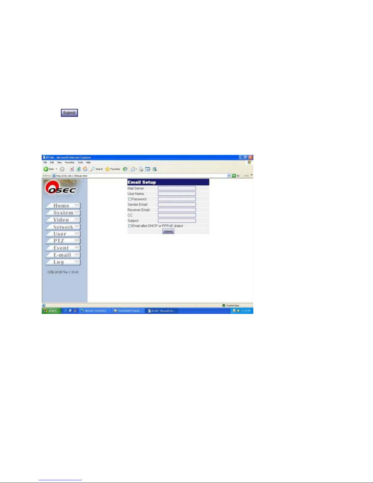
Email Setup
【Mail Server】: SMTP server account setup
【User Name】: User’s name account setup
【Password】: User’s password setup
【Sender Email】: Sender’s email account setup
【Receiver Email】: Receivers’ email account setup
【CC】: Carbon copy of multi-receiver divided by “;”
【Subject】: Subject of email message
Email after DHCP or PPPoE Dialed: User can send email to user after DHCP or PPPoE gets a new IP
Page 36
address for user can logon to the camera.
Click to save input data.
【
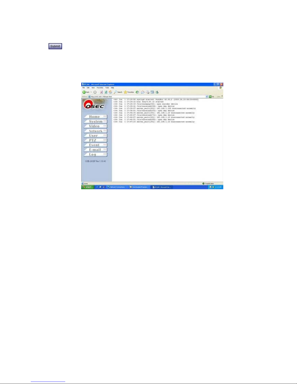
Log】
System offers user to review details of system operating records.
Page 37
IP Installer
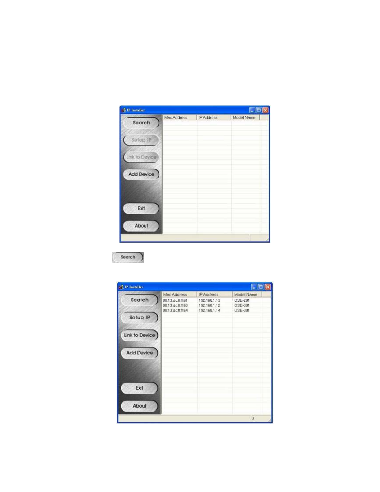
IP Installer can assist user locating wishful IP camera/video server and type appropriate IP
address onto product both in fastest and easiest way.
Search: User can click to get all the products in the same LAN subnet. Result will be
shown on the right table listed below.
Page 38
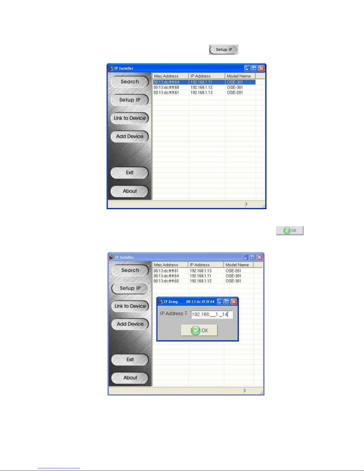
Setup IP: 1. Select one device listed on the right, and click to enter.
2. System will popup a window, type wishful IP address onto device, click , and
system write correct IP onto device.
Page 39
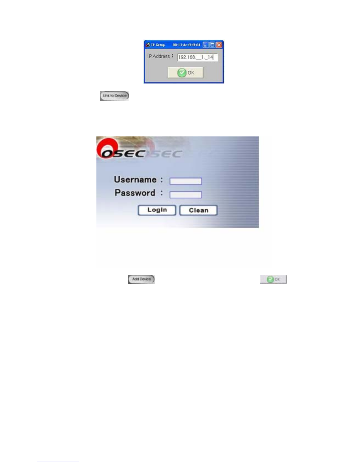
Link to Deice: Click to view real-time video and confirm new IP address has successfully
written onto device. As mentioned in the previous page, a verification window will
popup to ask to type username (default: root) and password (default: device MAC
address shown on the bottom of device).
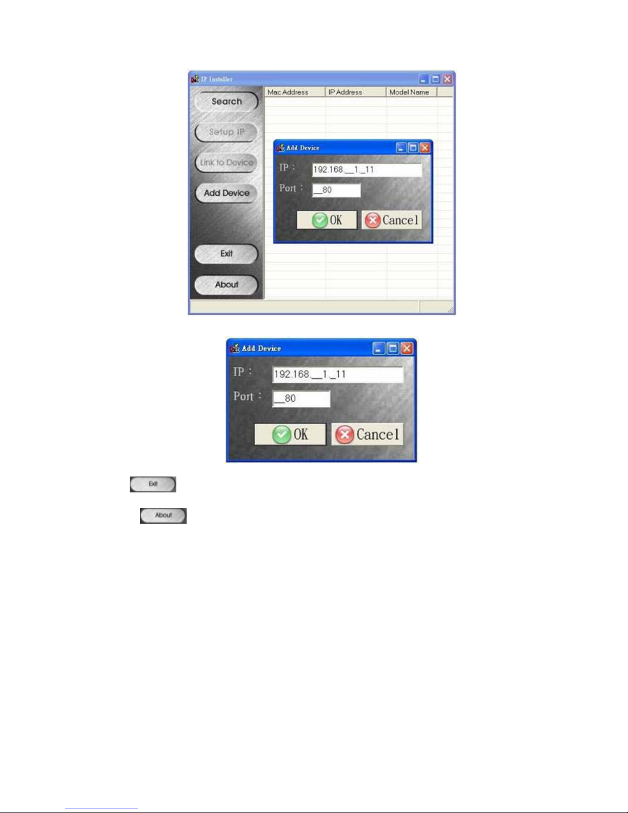
Add Device: If you want to login other IP camera/video server which not locates in the same LAN or
device on the Internet. Click
to login. Type IP address and click to add.
Page 40
Exit: Click to exit IP Installer.
About: Click to view manufacturer information.
Page 41

Appendix A DDNS Service
I. How to use DDNS
If user gets IP address from DHCP or dynamic IP address given from ISP
provider of XDSL, DDNS account is required to view video images.
There’re some websites offering free DDNS account, yet, some websites
offer DDNS service with service charge. Each account must be unique
that cannot repeat with others
When application is complete, DDNS website will detect user’s IP or
manually type IP address manually. When DDNS account writes onto
video server/IP camera and connect to DDNS website, DDNS will detect
IP address and correspond to DDNS account automatically.
II. Example: DDNS
Suppose DDNS website is TWSAFE.dyndns.org
DHCP assigns IP address 220.132.206.9 to video server
Connect to DDNS website and it will auto-detect or manually update
correspondent IP address: TWSAFE.dyndns.org= 220.132.206.9
Æ ▼
Page 42
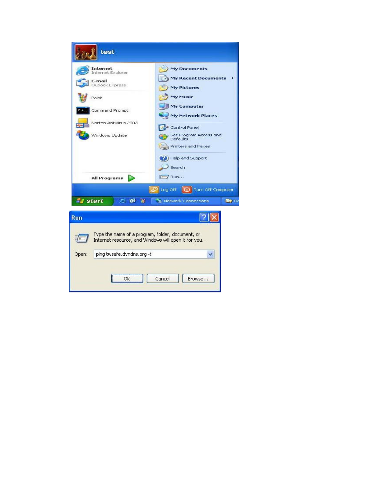
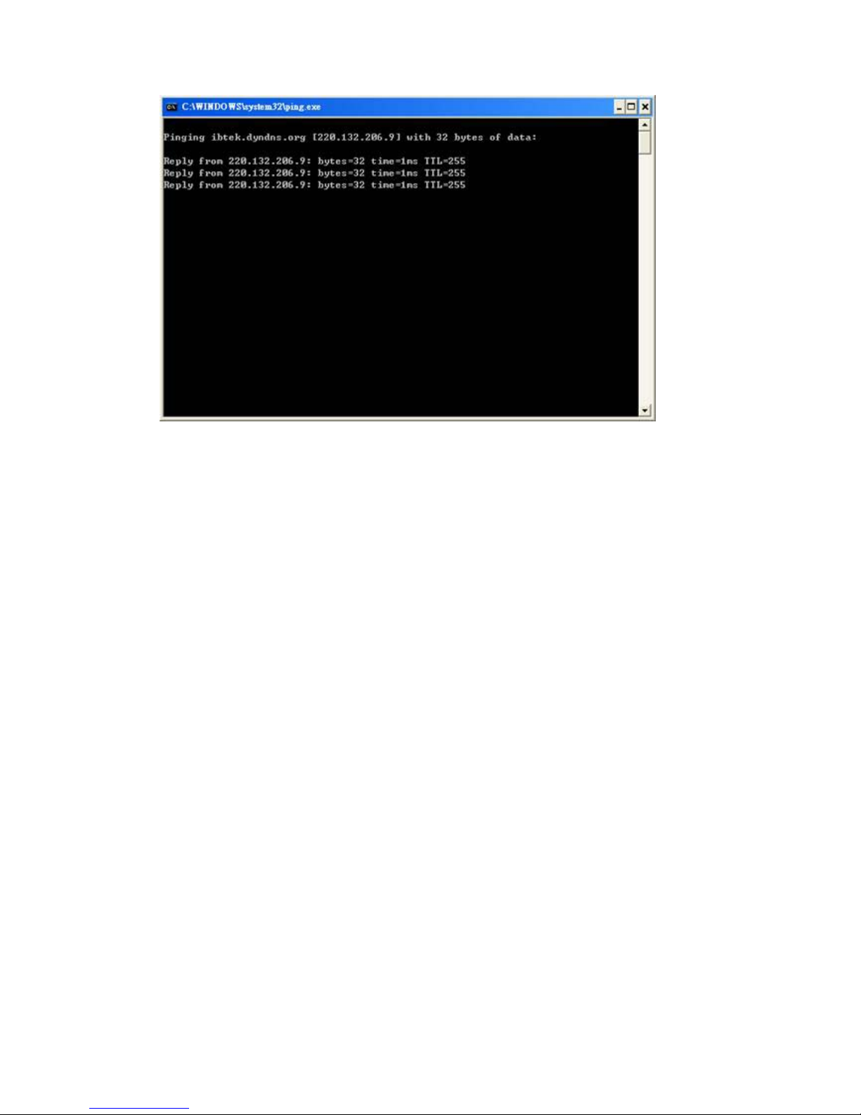
▲ Type: ping TWSAFE.dyndns.org –t
If system shows “Pinging TWSAFE.dyndns.org [220.132.206.9] with 32 bytes of
data:
Reply from 220.132.206.9: bytes=32 time=1ms TTL=255
It means DDNS has updated IP address successfully corresponding
TWSAFE.dyndns.org = 220.132.206.9
Page 43
If video server/IP camera reconnects to network, another new IP address will be
assigned, please follow the II steps listed above again to correspond DDNS.
Page 44
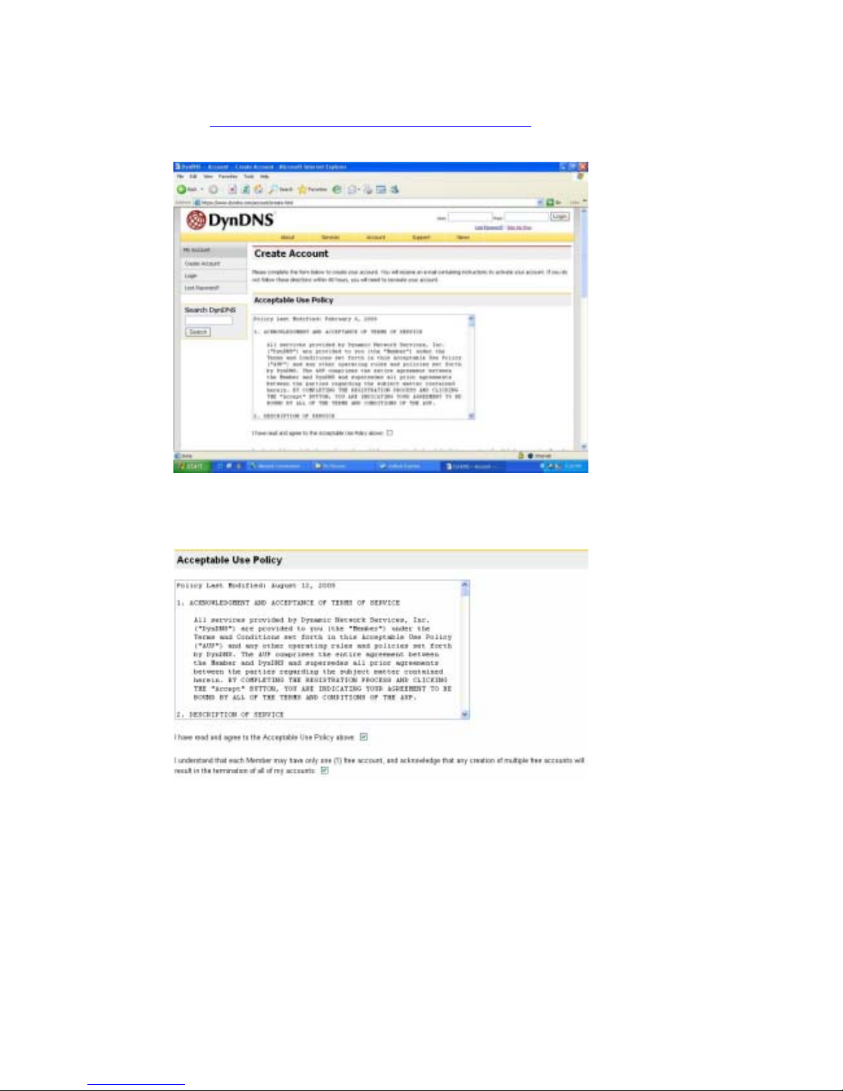
2. How to Apply DDNS Account
▼ http://www.dyndns.com/account/create.html
offers free DDNS account.
User can apply a free domain account from here.
▼ Acceptable Use Policy
User applies account with no repeated account with others, for example,
TWSAFE.tw
Type personal data.
Page 45
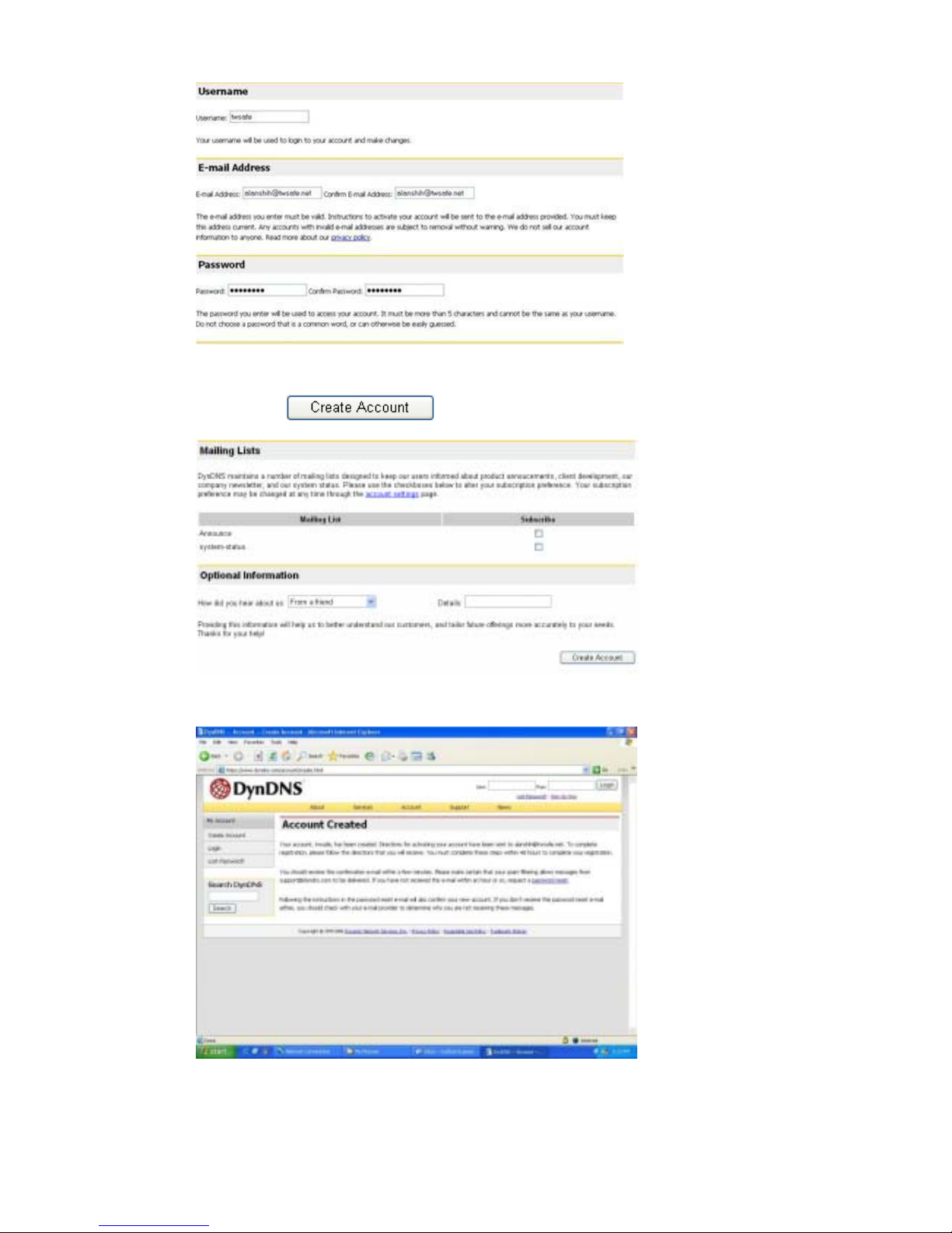
Click
after completion.
▼ Account Completed
▼ User will receive a confirmation email from dnydns.org. User needs
Page 46
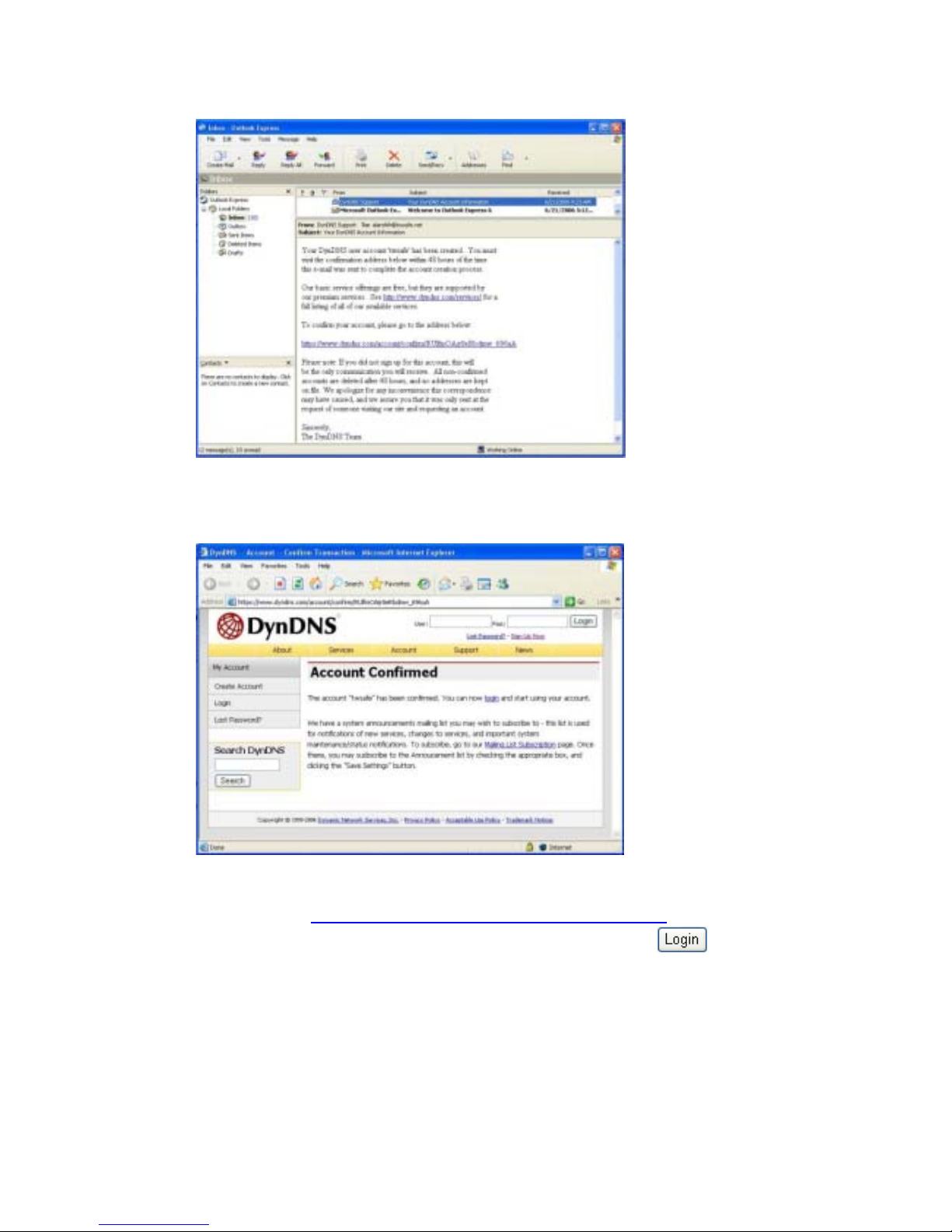
to click the address to confirm account.
▼ Account Confirmed
Logon to http://www.dyndns.com/account/login.html and click Login
on the left. Type account and password and click
Page 47
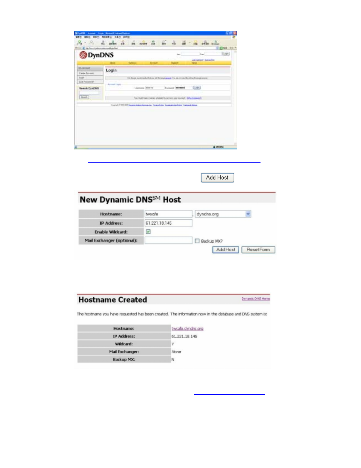
http://www.dyndns.com/account/services/hosts/dyndns/ and click
Hostname, then type wishful hostname (system will detect user’s IP
automatically), and click Add Host
Hostname Created
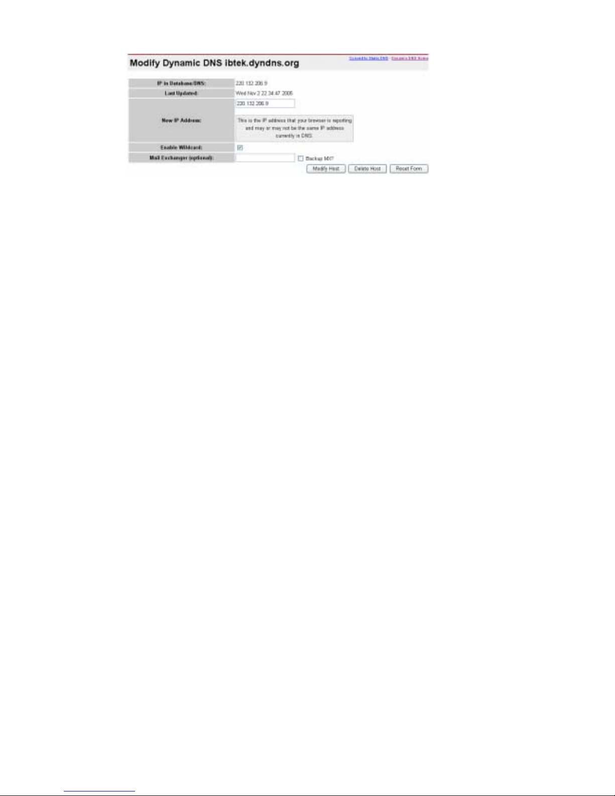
When IP address changes, DDNS http://www.dyndns.org will handshake
new IP address. User also can change IP address manually.
Page 48
Page 49

Appendix B Intellectual Property Right
TRADEMARKS
Oosec, a total subsidiary brand name under TWSAFE Inc., and TWSAFE are registered
trademarks, and are used under license. All other trademarks are the property of their respective
owners.
COPYRIGHT TWSAFE Inc., ALL RIGHTS RESERVED.
Copyright in the pages of quick installation guide, user’s manual, and images displaying on PC/PDA/laptop
computer, and software as attached in the package, and in the material contained therein and in their
arrangement, and hardware as attached in the package, is solo owned by TWSAFE, Inc. ("TWSAFE"), and/or its
affiliates, unless otherwise indicated.
In addition, the materials contained in the CD and stored in PC may be TWSAFE Proprietary and/or Trade Secret
information and may not be copied, compiled, or distributed without the prior written consent of TWSAFE
PERMITTED USE
Any person is hereby authorized to use the information available in the package/CD under license of TWSAFE for
informational purposes only. However, the text and images resident on CD or attached package may not
otherwise be copied, modified, distributed, reproduced or reused without written permission of TWSAFE.
Manufacturer: TWSAFE Inc.
Address: 7F, 428, Dung-hwa Rd.,
Taichung 406, Taiwan
Telephone: 886-4-22923948
Fax: 886-4-2292-3947
Email: [email protected]
Web: www.oosec.com
Page 50

Appendix C Limited Warranty
HARDWARE & SOFTWARE LIMITED WA RRANTY
TWSAFE CORP.. (TWSAFE), warrants to the original purchaser (“Purchaser”) i.e. distributor or reseller of
an IP surveillance product (“Product”) that the Product will be free from flaws in material or workmanship
for ONE year from the date of purchase. If a Product fails during the Warranty Period due to a defect in
material or workmanship, TWSAFE as its sole responsibility and Purchaser’s sole and exclusive remedy will,
at its opinion, either repair or replace the Product with the same or later version that performs substantially
the same function as the one being replaced. The Limited Warranty is contingent upon proper use of the
Product and does not cover any Product that has been damaged by misuse, accident, neglect, disaster,
improper installation, improper test, or abuse nor by any Product has been altered, modified, or replaced by
anyone other than TWSAFE.
THIS IS A LIMITED WARRANTY AND IT IS THE ONLY WARRANTY MADE BY TWSAFE. THIS
WARRANTY IS IN LIEU OF ALL OTHER WARRANTIES, EXPRESSED OR IMPLIED, INCLUDING
WITHOUT LIMITATIONS, THE IMPLIED WARRANTIES OF MERCHANTABILITY AND FITNESS
FOR A PARTICULAR PURPOSE
Any Product requiring service during Warranty period should be returned to TWSAFE in accordance with
the “Return Material Authorization” process set forth in documentation for that Product and in the current
TWSAFE Products and Services Guide.
EXCEPT FOR THE EXCLUSIVE REMEDY SET FORTH ABOVE, IN NO EVENT SHALL IP
SURVEILLANCE PRODUCT HAVE ANY LIABILITY TO PURCHASE ARE ANY THIRD PARTY FOR
ANY CLAIM, LOSS OF DAMAGE OF ANY KIND, EVEN IF IP SURVEILLANCE PRODUCT HAS
BEEN ADVISED OF THE POSSIBILITY OF SUCH DAMAGES, INCLUDING BUT NOT LIMITED TO
LOST PROFITS, CONSEQUENTIAL, INCIDENTAL, SPECIAL, PUNITIVE OR INDIRECT DAMAGES,
ARISING OUT OF OR IN CONNECTION WITH THE PERFORMANCE, USE OF OR ANY INABILITY
TO USE ANY PRODUCT OR ANY DATA, SOFTWARE OR EQUIPMENT RELATED THERETO OR
USED IN CONNECTION THEREWITH OR INFRINGMENT OF ANY PATENT, COPYRIGHT,
TRADEMARK OR ANY OTHER INTELLECTUAL PROPERTY RIGHT OF ANY THIRD PARTY. IN NO
EVENT SHALL IP SURVEILLANCE PRODUCT’S LIABILITY FOR DAMAGES, WHETHER ARISING
OUT OF CONTRACT, NEGLIENECE, WARRANTY OR INFRIGEMENT OF ANY INTELLECTUAL
PROPERTY RIGHT, EXCEED THE PURCAHSE PAID BY PURCHASER FOR THE PRODUCT.
Page 51

Appendix D PAL/NTSC Country/Region List
PAL:
ABU DHABI, AFGHANISTAN, ALBANIA, ALGERIA, ANDORRA, ANGOLA, ARGENTINA, ASCENSION
ISLAND, AUSTRALIA, AUSTRIA, AZORES, BAHRAIN, BANGLADESH, BELGIUM, BOSNIA
HERZEGOVINIA, BOTSWANA, BRAZIL, BRUNEI, BRUNEI, CAMEROON, CANARY ISLANDS, CAPE
VERDE, CAYMEN ISLANDS, CHINA, CHRISTMAS ISLAND, COOK ISLAND, CROATIA, CYPRUS, CYPRUS
(TURKISH), CZECH REPUBLIC (CT1, CT2 & PRIMA), DENMARK, DUBAI, EASTER ISLAND, EGYPT,
ERITREA, ETHIOPIA, FALKLAND ISLANDS, FAROE ISLANDS, FIJI, FINLAND, GAMBIA, GAZA & WEST
BANK, GERMANY, GHANA, GILBRALTAR, GREECE, GREENLAND, GUINEA, GUINEA-BISSAU,
HOLLAND, HONG KONG, ICELAND, INDIA, INDONESIA, IRELAND, ISRAEL, ITALY, JORDAN, KENYA,
KIRIBATI, KUWAIT, LAOS, LATVIA, LEBANON, LESOTHO, LIBERIA, LIECHTENSTEIN, LITHUANIA,
LUXEMBOURG, MACAU, MACEDONIA, MADEIRA, MALAWI, MALAYSIA, MALDIVES, MALTA,
MONACO, MONTENEGRO, MOZAMBIQUE, NAMIBIA, NEPAL, NETHERLANDS, NEW ZEALAND, NIGERIA,
NORFOLK ISLAND, NORWAY, OMAN, PAKISTAN, PAPUA NEW GUINEA, PARGUAY, POLAND,
PORTUGAL, QATAR, ROMANIA, SARDINIA, SAUDI ARABIA, SERBIA, SEYCHELLES, SIERRA LEONE,
SINGAPORE, SLOVAKIA REPUBLIC, SLOVENIA, SOLOMON ISLANDS, SOMALIA, SOUTH AFRICA, SPAIN,
SRI LANKA, SUDAN, SWAZILAND, SWEDEN, SWITZERLAND, SYRIA, TANZANIA, THAILAND, TONGA,
TRISTIAN DA CUNAH, TURKEY, UGANDA, UNITED ARAB EMIRATES, UNITED KINGDOM, URUGUAY,
VANUATU, VATICAN, YEMEN, YUGOSLAVIA, ZAMBIA, ZANZIBAR, ZIMBABWE
NTSC:
ALASKA, AMERICAN SAMOA, ANTIGUA, ANTILLES (DUTCH), ARUBA, BAHAMAS, BARBADOS,
BARBUDA, BELIZE, BERMUDA, BOLIVIA, BRITISH VIRGIN ISLANDS, BURMA, CANADA, CAYMEN
ISLANDS, CHILE, COLUMBIA, COSTA RICA, CUBA, CURACAO, DIEGO GARCIA, DOMINICA,
DOMINICAN REPUBLIC, ECUADOR, EL SALVADOR, GALAPAGOS ISLAND, GREENLAND, GRENADA,
GUAM, GUATEMALA, GUYANA (REPUBLIC), HAITI, HAWAII, HONDURAS, JAMAICA, JAPAN,
JOHNSTON ISLANDS, KOREA SOUTH, LEEWARD ISLANDS, MARIANA ISLANDS, MARSHALL ISLANDS,
MEXICO, MICRONESIA, MIDWAY ISLANDS, MONTSERRAT, MYANMAR, NICARAGUA, OKINAWA,
PALAU, PANAMA, PERU, PHILIPPINES, PUERTO RICO, SAMOA, ST KITTS AND NEVIS, ST LUCIA, ST
VINCENT, SURINAM, TAIWAN, TRINIDAD & TOBAGO, UNITED STATES OF AMERICA, VENEAUELA,
VIETNAM, VIRGIN ISLANDS
Manufacturer: TWSAFE INC.
Address: 7F, 428, Dung-hwa Rd., Bei-tung District
Taichung 406, Taiwan
Telephone: 886-4-22924477
Fax: 886-4-22923947
Email: [email protected]
 Loading...