

Two Way Array SAS-2WA-48 Installation Instructions Manual
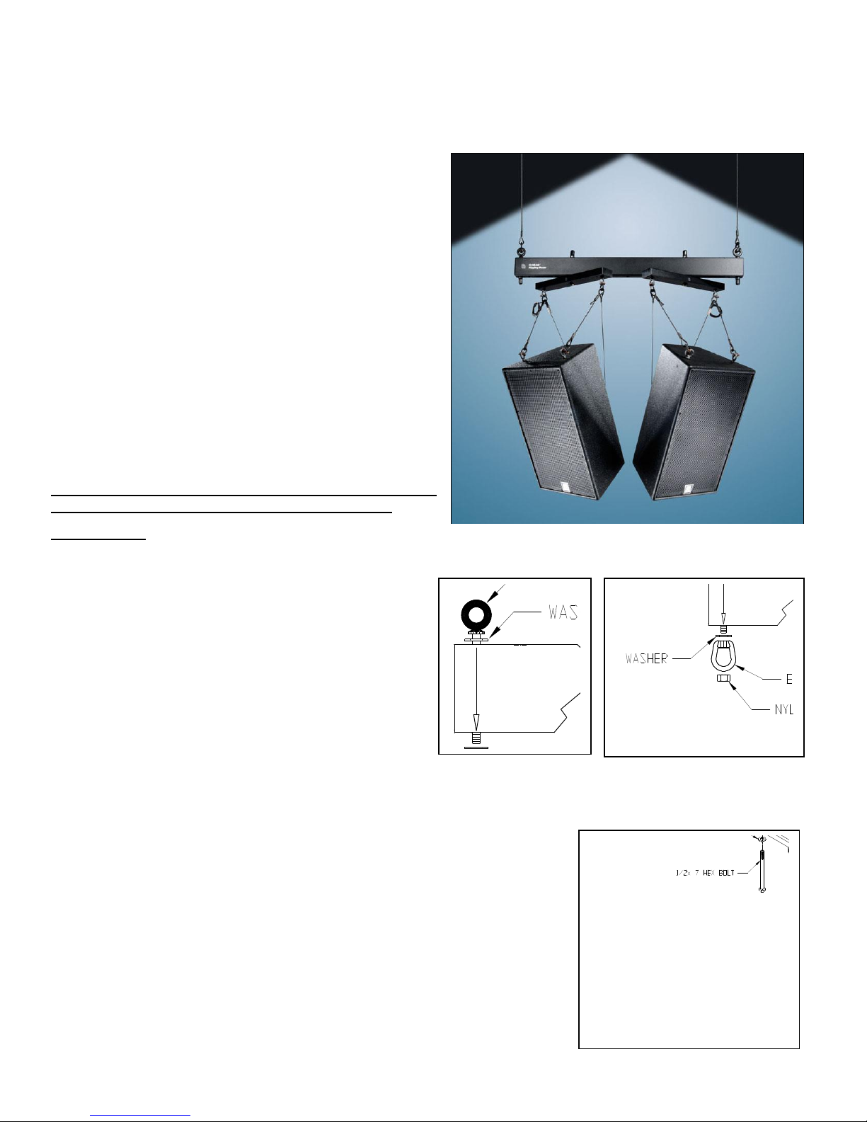
SAS-2WA-48 TwoWayArray
Figure 1A Figure 1B
SAS-2WA-48 Two Way Array
Figure 2:
Installation Instructions
_________________________________________________________________________________________________________
The TwoWayArray is a load rated overhead suspension
beam used for flying two loudspeaker cabinets and other
objects equipped with safe rigging points. This rigging system
allows for single and multiple tiered applications.
Important:
Due to the wide variety of overhead structures, rigging
materials and rigging methods, these instructions assume
that the installing contractor/installer will exercise good
judgment in selecting the proper suspension points, hardware
and mounting area.
Warning:
Mounting and rigging audio and video equipment requires
experienced professionals.
and video equipment can result in property damage,
personal injury, death and/or liability to the installing
contractor.
As a guide, the installation, when completed should be
capable of supporting at least 5 times the actual
Improperly installed audio
applied load.
Do not exceed the beam’s working load
limit. Use only Grade 8 hardware. If creating a grid, do
not exceed the grid’s working load limit.
Package Contents:
Qty: Description
1 pc. Rigging Beam (2 x 4 x 48”, or 66” long)
2 pcs. Gridlink Cross Arms
1 pc. Hardware Kit: Part#: 2-2975
Step 1. Check Cross Arm Placement:
If you need to move the cross arms towards the center or
farther away from the center, remove the nylock nuts, bolts
and flat washers from the cross arm. Select the desired
holes then reassemble the cross arms to the rigging beam
using the same hardware and in the same order (Figure 2).
Be sure the cross arms are moved equally to keep the system balanced and symmetrical.
Step 2: Prepare the Two Way Array Rigging System:
Install the outer suspension eyebolts, flat washers, and nylock nuts through the
outer holes of the beam with the eye of the eyebolt on the top side of the beam,
opposite the Cross Arms. Tighten permanently but do not crush tube (Figure 1A).
For
multiple tiered applications,
nylock nut (Figure 1B). Make sure the eyes of the eyebolts are perpendicular to
the length of the beam (Figure 1A/B). Tighten permanently but do not crush tube.
fasten eye nuts under the eyebolts then the
2015 Adaptive Technologies Group, Signal Hill, CA 90755 USA (562) 424-1100 091815
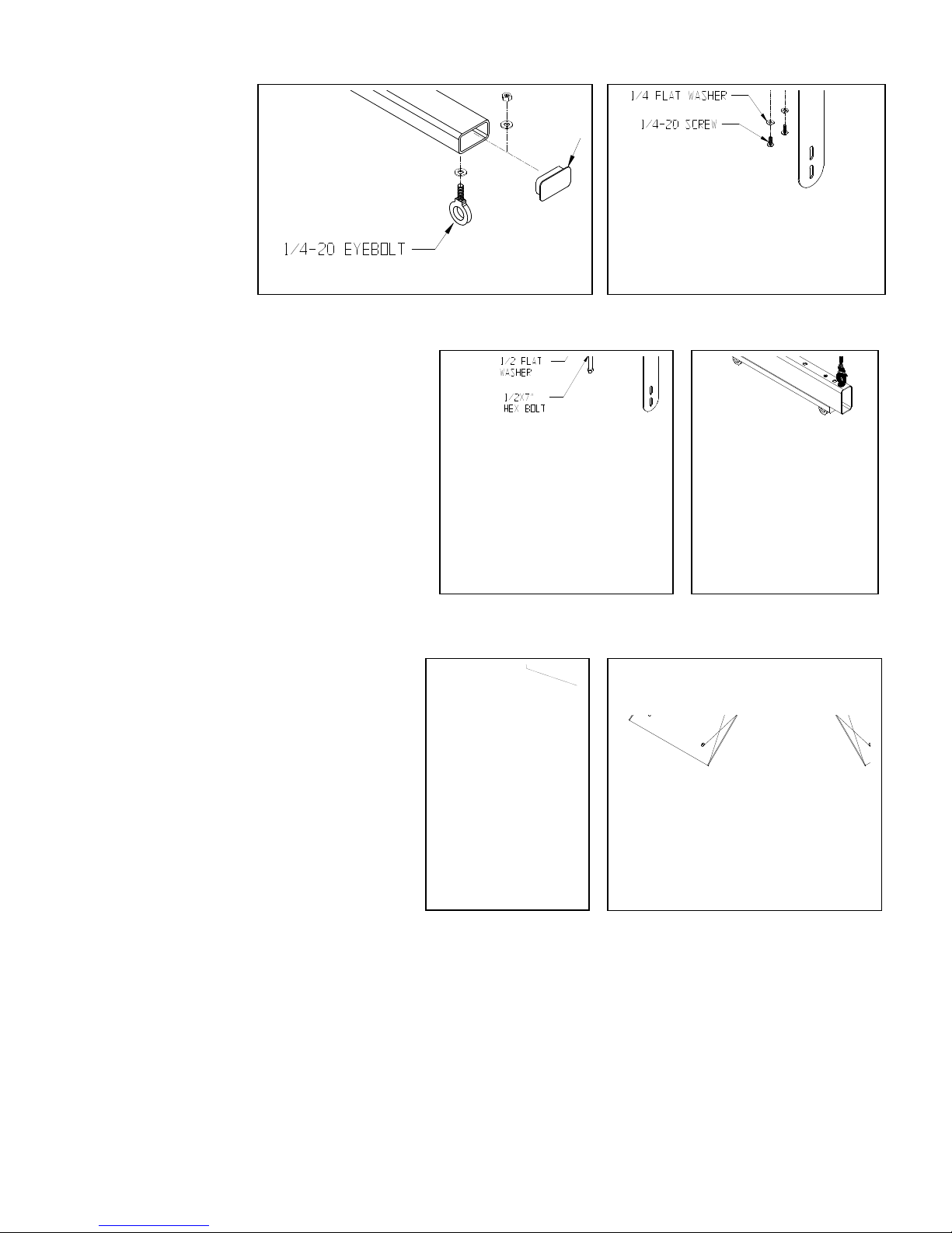
Figure 3B: U-Bracket Installation
Note:
Figure 3A: Rigging Application
Figure 3C: Figure 4:
Figure 5: Figure 6:
For U-Bracket, Remove
cross arm as in step 1,
install the U-Bracket to the
Cross Arm then
reassemble the cross arm
to the rigging beam using
the same hardware and in
the same order
Step 3.
Prepare Cross Arm:
For Rigging
(Adjustable
Tilt Cable Kit), install the
5/16” eyebolts to the
bottom holes at the end of the cross arm using flat
washers and nylock nuts. Tighten permanently. Press
fit the end caps on the ends of the cross arm tube.
(Figure 3A).
Prepare Cross Arm:
For U-Bracket
, attach the U-bracket to the four
holes underneath the cross arm using the provided
¼” x ¾” long screws, flat washers and nylock nuts.
Tighten permanently (Figure 3B).
Attach the Cross Arm/U-Bracket assembly to the
beam using the ½ x 7” hex bolt, friction washer, flat
washer, nylock nut and cotter pin. See U-Bracket
instruction sheet for more details.
Step 4. Suspend Two Way Array:
Suspend the TwoWayArray from the selected
suspension points using the two eyebolts on each
side of the beam. The hang angle should be as
close to vertical as possible. Make sure that the
combined suspension points are capable of
supporting at least 5 times the weight of the entire
load (figure 4).
For
multiple Tiered applications
, use eye nuts
(sold separately) underneath the beam’s eyebolts
as a hang point with rated shackles, cables and/or
chain. (Figure 1B). Make sure the eyes of the
eyebolts and eye nuts are perpendicular to the
beam’s length (Figure 4).
Step 5: Attach Rigging Hardware:
Suspend the selected loudspeaker and rigging hardware (Tilt cable kit or U-Bracket) from the eyebolts underneath the
cross arms using, load rated shackles, cables or other load rated fasteners (Figure 5).
Step 6: Adjusting the Horizontal Angle
Rotate the cross arm from the beam until the desired horizontal angle is achieved. Repeat the procedure to the other
cross arm (Figure 6).
Step 7. Adjusting the Tilt Angle:
See Adjustable Tilt Cable Kit or U-Bracket instruction sheet for more details.
Before hoisting, lift entire system a short distance and check each and every connection thoroughly before proceeding.
2015 Adaptive Technologies Group, Signal Hill, CA 90755 USA (562) 424-1100 091815
 Loading...