


MIXER USER MANUAL
B10F/B10F-PG
B15F/B15F-PG
14
ELECTRIC DIAGRAM
B10F/B10F-PG/B15F/B15F-PG Mixer Parts List
1C
NL
PE2
K4
K1
K1 overload protection switch
1C AC contact device
K2 bowl lift switch
K3 safety protect switch
K4 urgency stop switch
K5 switch
K reacor
K0 start switch
CA capacitor
M motor
M
K5
CA
K2 K3
K0
C
INDEX
PARTS CATALOG OVERVIEW
FIGURE 1 TRANSMISSION CASE, ARM, STAND
FIGURE 2 AXLE
FIGURE 3 GEAR AXLE
FIGURE 4 MOTOR UNIT
FIGURE 5 FORK AND SPEED SHAFT
FIGURE 6 ARM AND HANDWHEEL TYPEBOWL LIFTER UINT
FIGURE 7 HANDGRIP BOWL LIFTER UNIT
FIGURE 8 TURNING PLATEAND MIXING AXLE
FIGURE 9 STANDARDACCESSORIES
OPERATION INSTRUCTION
WARNINGAND SPECIAL ATTENTION
TROUBLE SHOOTING AND SPECIFICTION
ELECTRIC DIAGRAM
1
2
3
4
5
6
7
8
9
12
13
10
11
14
13
TROUBLE SHOOTING AND SPECIFICTION
Trouble Possible Causes Re-cover
The axle can'twork when operate
the machine.
SPECIFICTION
The mixing bowlout of position.
Leak oil.
Defficult to movethe bowl up and
down.
The motor isoverheat and speed
down.
Noise and overheat.
Mixer touch thebowl.
Poor contact ofthe electrical equipment.
Moving direction isnot correct.
Sealing washer isdamaged.
Slideway is rusted.
The voltage isnot enough, or incorrect speed.
Poor lubrication.
The mixing deviceor bowl deformed.
Change.
Check the plug.
Clean the slidewayand lubrication.
Check the voltageor use lower speed.
Add or changelubrication.
Repair or changethe bowl or mixing device.
TROUBLE SHOOTING
Mixer L
Power Supply V
Input Power W
Maxflour Capacity(kg)
Mixing
Speed
r.p. m
Type
10
600
508
258
156
2.5
110 V
B10F
15
600
3.5
110 V
B15F
10
600
480
244
148
2.5
220~240V
B10F
15
600
480
244
148
3.5
B15F
508
258
156
10
600
508
258
156
2.5
110 V
B10F-PG
10
600
480
244
148
2.5
220~240V
B10F-PG
220~240V
15
600
3.5
110V
15
600
480
244
148
3.5
508
258
156
220~240V
B15F-PG B15F-PG
B10F/B10F-PG/B15F/B15F-PG Mixer Parts List

2
1
3
4
5
Descviption
Item
1
3
5
2
4
1
PARTS CATALOG
OVERVIEW
NOTES:
The no using pipe line sprays to wash
the mixer
Wet hand in no using contact switch
with power supply plug.
While maintaining the mixer, must pull
out first the power supply plug, and from
profession the personnel maintains.
ring
rear cover
french
Mixing deviceIII
bowl
12
1 DON'T USE WATER PIPE TOWASHTHEMIXER DIRECTLY;
2 PLEASE PULL OFF THE PLUG BEFORE MAINTAINNING, AND MAKE IT
MAINTAINED BYPROFESSIONALS;
3 DON'T TOUCHTHE SWITCHSAND PLUG WITH WET HAND;
4 IF BROKEN, PLEASE STOP USINGATONCE
5 THERE ISAGROUNDED NUT (SIGNED " ") IN THE MACHINE, PLEASE
RECOVER IT TO ORIGIN CONDITION, DON'T CANCEL THE GROUNDED LINE;
6 DON'T PUT HANDS INTO THE BOWL OR TOUCHTHE MIXING DEVICES WH-
EN WORKING;
7 DON'TALLOW THE MINOR CLOSE TOTHE MACHINE;
8 THE MACHINE SHOULD BE FIXED ON THE DRY WOODEN SPLINTAND WO-
RK IN SAFE AREA;
9 IF THE ELECTRICAL WIRE IS BROKEN, PLEASE CHANGE IT BY PROFECTIO-
NALS.
1 BEFORE USING , PLEASE CLEAN THE BOWLAND THE MIXING DEVICES CAR-
EFULL Y,AND THEN INSTALL THE BOWL ONTO THE MACHINE CORRECTL Y
AND TIGHTL Y;
2 WHEN CHOOSING MIXING DEVICES, PLEASE REFER TO THE OPERA TION MA-
NUAL TO CHOSE THE CORRECT SPEED, OR IT WILL DESTOR YTHE INSIDE SP A-
RE PAR TSAND SHORTEN THE USING LIFE OF THE MACHIE;
3 AFTER USING, PLEASE POWER OFF THE MACHINE, AND PUT THE BOWLAND
DEVICES IN THE SAFE AND CLEAN PLACE AFTER CLEANING;
4 KEEP ENVIROMENTARROUND THE MACHINE DR Y HEAL THAND SAFE.
WARNINGAND SPECIALATTENTION
WARNING
SPECIALATTENTION
B10F/B10F-PG/B15F/B15F-PG Mixer Parts List B10F/B10F-PG/B15F/B15F-PG Mixer Parts List

Qty
15
16
17
1
5
1
1
1
1
2
axle
14
2
1
3
4
5
6
Descviption
Item
4
1
7
8
Figure 1 TRANSMISSION CASE,ARM, STAND
NOTES
Machine at a factory hour have added to
note the superior quality lubricates the
grease, usually the circumstance bottom
can use for several years, but machine is
after maintaining, must replace the lubrication grease.
cover
screw M5*35
plate
bearing 6202
bearing 6201
screw M5*12
bearing cover
screw M5*20
screw
axle
1
2
4
3
8
9
7
10
11
13
12
4
5
6
18
1
1
4
1
1
1
10
9
11
12
13
14
1
1
15
16
rear cover
body
screw M6*55
screw M5*12
arm
stand
capacitor board
1
1
17
18
capacitor
seat
breeze window
21
20
19
1
19
safefy coveringswitch
1
1
20
21
fluctuate safetyswitch
overload protectionswitch
11
OPERATION INSTRUCTION
Before using, please check power supply if it match
your machine and be sure ground wire is eliable.
Before testing, please take mixing device off first, in
order to avoid damage machine which is match moving direction. It's necessary to change the three-phase machine if the moving direction is not match with arrow.
Mixing: according to the different mixing-material.
Choose the different mixing devices and speed.
A: Be suitable for mix and stir butter, eggs, and work with in high speed, working time is less than 15 minutes.
B. Be suitable for mix and stir stuffing and raw material,
and work in middle speed, working time is less than 20
minutes.
C: middle position is suitable for mixing dough,
working time is less than 30 minutes.
Flour wat-
er quantity is 40%-50%.
A
B
C
110V
OPERATION INSTRUCTION
For changing the speed: Please stop machine first
before change speed in order to aviod damage gear
box.
OFF
220~240V
B10F/B10F-PG/B15F/B15F-PG Mixer Parts List B10F/B10F-PG/B15F/B15F-PG Mixer Parts List
3
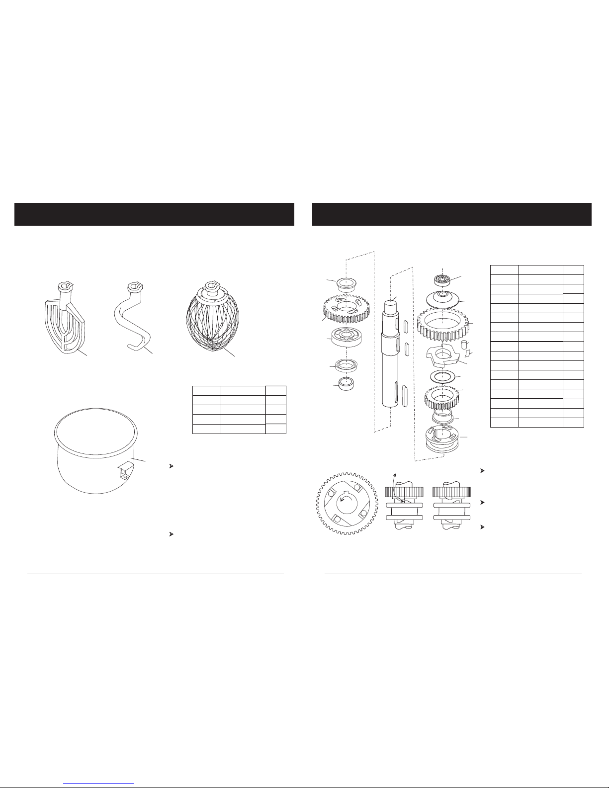
Figure 2 AXLE
Be sure to install correct position
(see Figure 2-1) and lubricate all
of the pins in the sleeve drive when reassembling.
Joint (7) must always be raised
and lowered smoothly. Be sure joint sleeve as shown in Figure 2-2.
Check oil seal, if serious oil leaks
from drip cup.
RIGHT WRONG
FIGURE 2-1 FIGURE 2-2
Vertical sidesof jaws must face
on another.
16
14
13
11
6
5
4
7
9
8
3
10
Qty
1
1
1
1
1
1
2
3
4
5
big jointgear
bearing ring
Descviption
Item
bearing 6204
1
1
6
7
axle
joint
1
1
1
1
8
9
10
11
bearing ring
dividing ring
roller
joint gear
4
8
12
13
engager
1
1
14
15
gear ring
plate ring
NOTES
15
spring
12
1
16
bearing 6001
2
1
cover
oil seal25*40*10
10
1
2
3
4
Qty
1
1
1
1
1
2
3
4
Descviption
Item
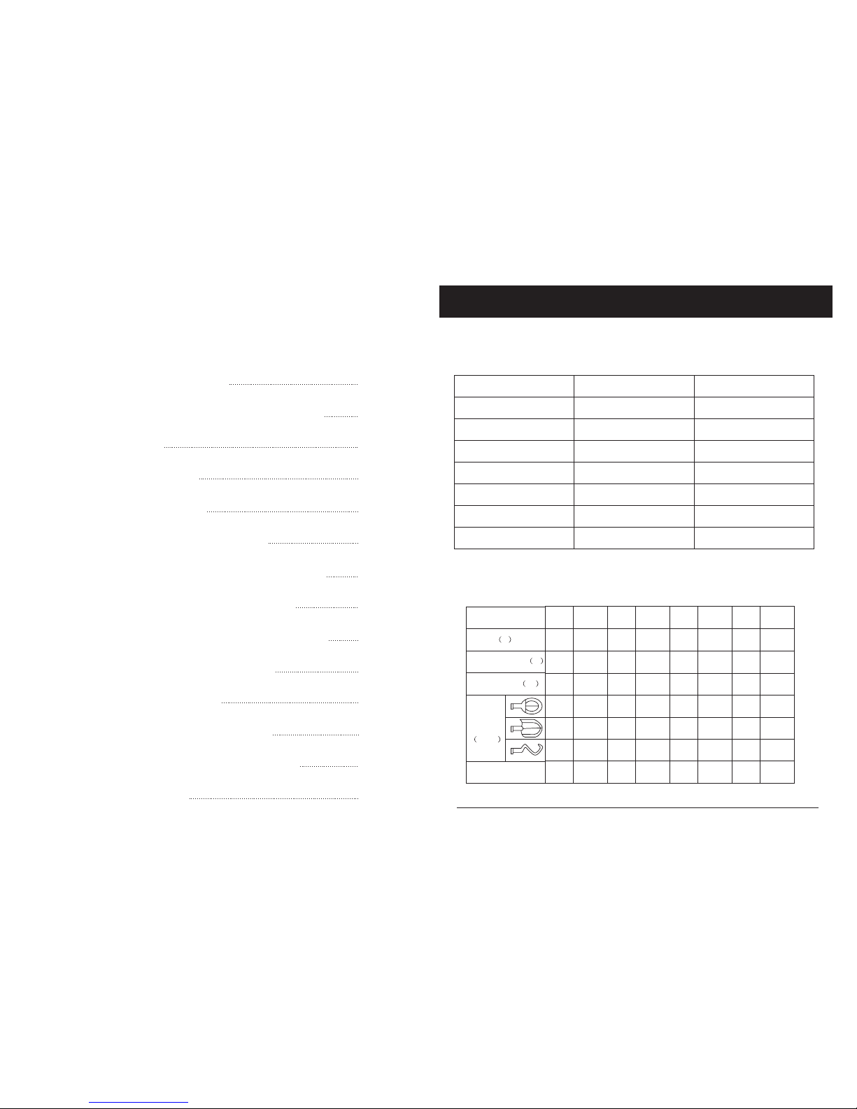
Figure 9 STANDARD ACCESSORIES
NOTES
Any agitator is easily installed by simp-
ly raising it onto the mixing axle, and
then rotating it counter-clockwise on t-
he shaft until into place. To remove, ra-
ise the agitator on the shaft until it clea-
rs the lock and then rotate clockwise an-
d lower.
All of tools are precisely fitted to the bo-
wl, rounded corners and easily remov-
able for cleaning.
bowl
Mixing deviceI
Mixing deviceII
Mixing deviceIII
B10F/B10F-PG/B15F/B15F-PG Mixer Parts List B10F/B10F-PG/B15F/B15F-PG Mixer Parts List

4
2
4
5
6
7
8
Qty
1
1
1
2
1
1
2
3
4
5
bearing 6001
key 5*58
collar
gear
Descviption
Item
gear axle
1
1
6
7
gear
Figure 3 GEAR AXLE
NOTES
Be sure that the keys are inserted
for each gear.
1
3
9
1
1
8
long collar
1
9
gear
stop ring
9
Figure 8 TURNING PLATEAND MIXINGAXLE
5
9
7
3
2
6
8
10
4
1
11
Qty
1
1
1
1
1
1
2
3
4
5
mixing axle
Oil seal20*40*10
safety net
planetary gear
Descviption
Item
bearing 6003
1
1
6
7
turning plate
inner gear
1
1
1
8
9
10
cover
screw M8*20
bearing 6203
1
11
ring
B10F/B10F-PG/B15F/B15F-PG Mixer Parts List B10F/B10F-PG/B15F/B15F-PG Mixer Parts List

5
spiral
oil seal
bearing 203
axle
switch
switch plastic
bearing cover
fan
Figure 4-1
1
2
3
4
5
11
9
8
3
7
6
Qty
1
2
1
1
1
1
2
3
4
5
spiral
oil seal
key 4*22
axle
Descviption
Item
bearing 203
1
1
6
7
switch
switch plastic
4
2
1
8
9
10
screw M4*8
bearing cover
screw M6*16
Figure 4 MOTOR UNIT
NOTES
If the motor does not work, first v-
erify the power source and conn-
ection. Next, check for damaged
or faulty wiring or connections ins-
ide the mixer.A noworking motor
may be the result of inappropriate
voltage, broken wires, a defective
capacitor, or a defective centrifugal
governor. Motor damage may also
be caused by bowl overload during
mixing.
Motor set includes motor axle,rotor
and stator.
Figure 4-1 is component system
diagrams of motor.
1
11
fan
10
11
10
8
9
7
6
2
1
3
5
12
3
3
4
4
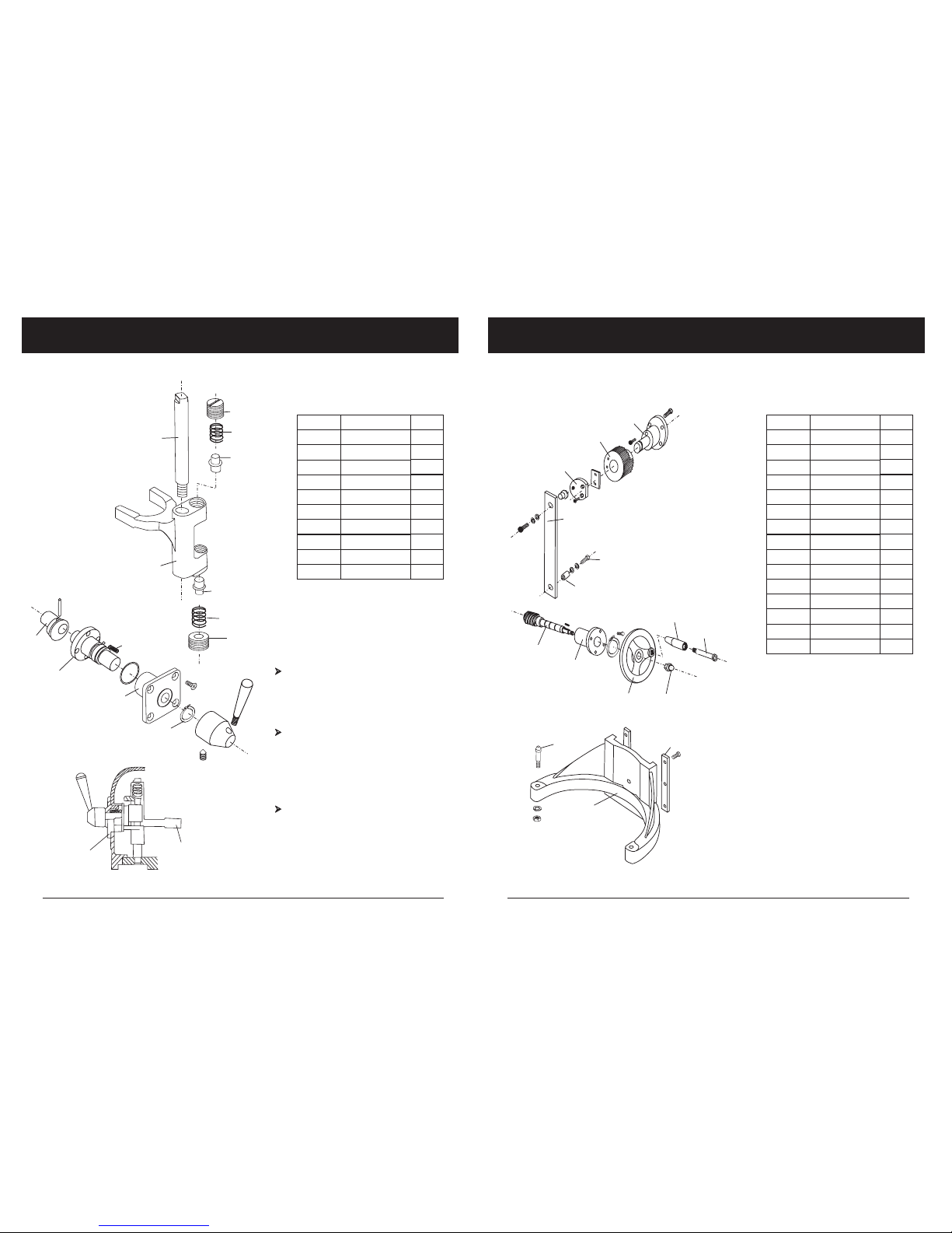
Figure 7 HANDGRIP TYPE BOWL LIFTER UINT
Qty
Descviption
Item
2
1
1
3
1
2
3
4
lifting bar
nut M10
flat washer
cottor pin3*30
1
1
1
1
5
6
7
8
compression spring
lifting handlebracket
flat washer
1
9
flange knot
1
1
1
10
11
12
screw M6*25
bowl lifthandle
key 5*20
little knot
8
B10F/B10F-PG/B15F/B15F-PG Mixer Parts List B10F/B10F-PG/B15F/B15F-PG Mixer Parts List
6
1
5
3
4
2
6
7
9
8
10
fork
speed block
Qty
2
2
1
1
2
1
2
3
4
5
axle
fork
shaft
nut
Descviption
Item
spring
1
1
6
7
bearing ring
speed block
1
2
1
8
9
10
spring
plate
shaft
Figure 5 FORK AND SPEED SHAFT
NOTES
The speed selector / shifting mech-
anism is designed for simplicity and
reliability. It features three mixing s-
peeds.
Speed selection is made by aligning
the pointer of the shifter handle with
the proper number on the shift sele-
ctor. Stop the mixer befor making any
speed changes.
Apply sealant to the shift selector as-
sembly, and install it .
3
4
5
7
7
6
5
4
8
9
10
11
12
15
13
14
1
2
3
Qty
1
2
1
2
1
1
2
3
4
5
Descviption
Item
1
1
6
7
1
1
1
8
9
10
1
11
1
1
12
13
1
1
14
15
Figure 6 ARM AND BOWL LIFTER UINT
screw
arm
pull pole
plate
plate
gear
brace seat
screw M8*20
spiral
sleev
french support
french
handle
handle screw
nut
B10F/B10F-PG/B15F/B15F-PG Mixer Parts List B10F/B10F-PG/B15F/B15F-PG Mixer Parts List
 Loading...