

Page 1

TWOSE
TE480
Hedgecutter / Trimmer
Operator Manual
Publication 519 July 2006 (Revised 29.11.10)
Page 2

Page 3

IMPORTANT
VERIFICATION OF WARRANTY REGISTRATION
DEALER WARRANTY INFORMATION & REGISTRATION VERIFICATION
It is imperative that the selling dealer registers this machine with Twose of Tiverton Limited
before delivery to the end user – failure to do so may affect the validity of the machine
warranty.
To register machines go to the Twose web site at www.twose.com, log onto ‘Dealer
Inside’ and select the ‘Machine Registration button’ which can be found in the Service
Section of the site. Confirm to the customer that the machine has been registered in the
section below.
Should you experience any problems registering a machine in this manner please contact
the Twose Office on 01884 253691.
Registration Verification
Dealer Name: ……………………..…………………………………………………………….
Dealer Address: …….………………………………………………………………………….
Customer Name: ……………………..…………………………………………………………
Date of Warranty Registration: ……/……/...…… Dealer Signature: ………………..……
NOTE TO CUSTOMER / OWNER
Please ensure that the above section above has been completed and signed by the selling
dealer to verify that your machine has been registered with Twose of Tiverton Limited.
IMPORTANT: During the initial ‘bedding in’ period of a new machine it is the customer’s responsibility
to regularly inspect all nuts, bolts and hose connections for tightness and re-tighten if required. New
hydraulic connections occasionally weep small amounts of oil as the seals and joints settle in – where
this occurs it can be cured by re-tightening the connection – refer to torque settings chart below. The
tasks stated above should be performed on an hourly basis during the first day of work and at least
daily thereafter as part of the machines general maintenance procedure.
TORQUE SETTINGS FOR HYDRAULIC FITTINGS
HYDRAULIC HOSE ENDS PORT ADAPTORS WITH BONDED SEALS
BSP Setting Metric BSP Setting Metric
1/4” 18 Nm 19 mm 1/4” 34 Nm 19 mm
3/8” 31 Nm 22 mm 3/8” 47 Nm 22 mm
1/2” 49 Nm 27 mm 1/2” 102 Nm 27 mm
5/8” 60 Nm 30 mm 5/8” 122 Nm 30 mm
3/4” 80 Nm 32 mm 3/4” 149 Nm 32 mm
1” 125 Nm 41 mm 1” 203 Nm 41 mm
1.1/4” 190 Nm 50 mm 1.1/4” 305 Nm 50 mm
1.1/2” 250 Nm 55 mm 1.1/2” 305 Nm 55 mm
2” 420 Nm 70 mm 2” 400 Nm 70 mm
Page 4

WARRANTY POLICY
WARRANTY REGISTRATION
All machines must be registered, by the selling dealer with Twose of Tiverton Limited before delivery to the
end user. On receipt of the goods it is the buyer’s responsibility to check that the Verification of Warranty
Registration in the Operator’s Manual has been completed by the selling dealer.
1. LIMITED WARRANTIES
1.01. All machines supplied by Twose of Tiverton Limited are warranted to be free from defects in material
and workmanship from the date of sale to the original purchaser for a period of 12 months, unless a
different period is specified.
1.02. All spare parts supplied by Twose of Tiverton Limited are warranted to be free from defects in material
and workmanship from the date of sale to the original purchaser for a period of 6 months.
1.03. The manufacturer will replace or repair for the purchaser any part or parts found, upon examination at
its factory, to be defective under normal use and service due to defects in material or workmanship.
Returned parts must be complete and unexamined.
1.04. This warranty does not apply to any part of the goods, which has been subjected to improper or
abnormal use, negligence, alteration, modification, fitment of non-genuine parts, accident damage, or
damage resulting from contact with overhead power lines, damage caused by foreign objects (e.g.
stones, iron, material other than vegetation), failure due to lack of maintenance, use of incorrect oil or
lubricants, contamination of the oil, or which has served its normal life. This warranty does not apply to
any expendable items such as blades, flails, flap kits, skids, soil engaging parts, shields, guards, wear
pads or pneumatic tyres.
1.05. Temporary repairs and consequential loss - i.e. oil, downtime and associated parts are specifically
excluded from the warranty.
1.06. Warranty on hoses is limited to 12 months and does not include hoses which have suffered external
damage. Only complete hoses may be returned under warranty, any which have been cut or repaired
will be rejected.
1.07. Machines must be repaired immediately a problem arises. Continued use of the machine after a
problem has occurred can result in further component failures, for which Twose of Tiverton Limited
cannot be held liable, and may have safety implications.
1.08. Except as provided herein, no employee, agent, dealer or other person is authorised to give any
warranties of any nature on behalf of Twose of Tiverton Limited.
1.09. For machine warranty periods in excess of 12 months the following additional exclusions shall apply:
1) Hoses, external seals, exposed pipes and hydraulic tank breathers.
2) Filters.
3) Rubber mountings.
4) External electric wiring.
N.B. Warranty cover will be invalid if any non-genuine parts have been fitted or used. Use of nongenuine parts may seriously affect the machine’s performance and safety. Twose of Tiverton Limited
cannot be held responsible for any failures or safety implications that arise due to the use of nongenuine parts.
Page 5

2. REMEDIES AND PROCEDURES
2.01. The warranty is not effective unless the Selling Dealer registers the machine, via the Twose web site
and confirms the registration to the purchaser by completing the Verification of Warranty Registration
in the operator’s manual.
2.02. Any fault must be reported to an authorised Twose dealer as soon as it occurs. Continued use of a
machine, after a fault has occurred, can result in further component failure for which Twose of Tiverton
Limited cannot be held liable.
2.03. Repairs should be undertaken within two days of the failure. Claims submitted for repairs undertaken
more than 2 weeks after a failure has occurred, or 2 days after the parts were supplied will be rejected,
unless the delay has been authorised by Twose of Tiverton Limited.
2.04. All claims must be submitted, by an authorised Twose Service Dealer, within 30 days of the date of
repair.
2.05. Following examination of the claim and parts the manufacture will pay, at their discretion, for any valid
claim the cost of any parts and an appropriate labour allowance if applicable.
2.06. The submission of a claim is not a guarantee of payment.
2.07. Any decision reached by Twose of Tiverton Limited is final.
3. LIMITATION OF LIABILITY
3.01. The manufacturer disclaims any express (except as set forth herein) and implied warranties with
respect to the goods including, but not limited to, merchantability and fitness for a particular purpose.
3.02. The manufacturer makes no warranty as to the design, capability, capacity or suitability for use of the
goods.
3.03. Except as provided herein, the manufacturer shall have no liability or responsibility to the purchaser or
any other person or entity with respect to any liability, loss, or damage caused or alleged to be caused
directly or indirectly by the goods including, but not limited to, any indirect, special, consequential, or
incidental damages resulting from the use or operation of the goods or any breach of this warranty.
Notwithstanding the above limitations and warranties, the manufacturer’s liability hereunder for
damages incurred by the purchaser or others shall not exceed the price of the goods.
3.04. No action arising out of any claimed breach of this warranty or transactions under this warranty may be
brought more than one (1) year after the cause of the action has occurred.
4. MISCELLANEOUS
4.01. The manufacturer may waive compliance with any of the terms of this limited warranty, but no waiver
of any terms shall be deemed to be a waiver of any other term.
4.02. If any provision of this limited warranty shall violate any applicable law and is held to be unenforceable,
then the invalidity of such provision shall not invalidate any other provisions herein.
4.03. Applicable law may provide rights and benefits to the purchaser in addition to those provided herein.
Page 6

Page 7

THIS MANUAL IS TO BE HANDED TO THE CUSTOMER BEFORE
THE MACHINE IS TO BE USED FOR THE FIRST TIME.
THIS MANUAL (OR A COPY OF) MUST BE USED AND READ BY
ALL OPERATORS OF THIS MACHINE.
TWOSE OF TIVERTON LIMITED
6 CHINON COURT
LOWER MOOR WAY
TIVERTON BUSINESS PARK
TIVERTON
DEVON
EX16 6SS
Telephone: 01884 253691
Fax: 01884 255189
All dimensions and capacities mentioned in this book are approximate. In pursuance of the company’s
policy of constant development, the right is reserved to depart, without notice, from any detail illustrated
or specified in this book, without incurring the obligation to provide such modifications on the machine
previously delivered.
No responsibility will be accepted by Twose of Tiverton Limited for any injury, damage or loss arising
from the improper use of or lack of maintenance of any machinery supplied by them or from any failure
of the user to comply with all instructions published by Tractor or Loader Manufacturers, particularly
with the regard to maximum load capacities, tyre pressures and stability, or with instructions and
regulations pertaining to Tractor Cabs.
Page 8

DECLARATION OF CONFORMITY
Conforming to EU Machinery Directive 2006/42/EC
We,
TWOSE of TIVERTON LIMITED,
6 Chinon Court, Lower Moor Way,
Tiverton Business Park, Tiverton, Devon, EX16 6SS, UK
Hereby declare that:
The Product; Tractor Mounted Hedgecutter / Grass Mower
Product Code; T480
Serial No. & Date ………………………………… Type …………………………
Manufactured in; United Kingdom
Complies with the required provisions of the Machinery Directive 2006/42/EC
The machinery directive is supported by the following harmonized standards;
BS EN ISO 14121-1 (2007) Safety of machinery - Risk assessment, Part 1:
Principles Part 2: practical guide and examples of methods.
BS EN ISO 12100-1 (2010) Safety of machinery - Part 1: Basic terminology and
methodology Part 2: Technical principles.
BS EN 349(1993)+ A1 (2008) Safety of machinery - Minimum distances to avoid the
entrapment with human body parts.
BS EN 953 (1998) Safety of machinery - Guards General requirements for the
design and construction of fixed and movable guards.
BS EN 982(1996)+ A1 (2008) Safety requirements for fluid power systems and their
components. Hydraulics
Signed ……………….... Responsible Person
on behalf of TWOSE of TIVERTON LIMITED
Status: General Manager Date: May 2011
Page 9

DECLARATION OF CONFORMITY
Conforming to EU Machinery Directive 2006/42/EC
We,
TWOSE of TIVERTON LIMITED,
6 Chinon Court, Lower Moor Way,
Tiverton Business Park, Tiverton, Devon, EX16 6SS, UK
Hereby declare that:
The Product; Hydraulic Arm Mounted Flailhead
Product Code; TWHD
Serial No. & Date ………………………………… Type …………………………
Manufactured in; United Kingdom
Complies with the required provisions of the Machinery Directive 2006/42/EC
The machinery directive is supported by the following harmonized standards;
BS EN ISO 14121-1 (2007) Safety of machinery - Risk assessment, Part 1:
Principles Part 2: practical guide and examples of methods.
BS EN ISO 12100-1 (2010) Safety of machinery - Part 1: Basic terminology and
methodology Part 2: Technical principles.
BS EN 349(1993)+ A1 (2008) Safety of machinery - Minimum distances to avoid the
entrapment with human body parts.
BS EN 953 (1998) Safety of machinery - Guards General requirements for the
design and construction of fixed and movable guards.
BS EN 982(1996)+ A1 (2008) Safety requirements for fluid power systems and their
components. Hydraulics
Signed ……………….... Responsible Person
on behalf of TWOSE of TIVERTON LIMITED
Status: General Manager Date: May 2011
Page 10

Page 11

LIST OF CONTENTS
Page No.
Specifications 1
General Information 2
Features 3
Safety Information
4
Introduction
10
Tractor Selection
12
Hydraulic Oil
13
Machine Attachment – Chain Type Stabilizer
14
Machine Attachment – Link Type Stabilizer
17
Operation Information
21
Rotor Rotation Direction
21
Rotor Control
22
Cable Controls – Levers and Symbols
23
Cable Controls – Lever Functions
24
Hydraulic Controls – Cutting Position
25
Cutting Head
25
Transportation
26
Cutting Head Belt Adjustment
27
Cutting Head Belt Replacement
28
Rotor Removal & Replacement
29
Roller Height Adjustment
30
Machine Removal
31
Maintenance
32
Page 12

1
NOISE
The equivalent daily personal noise exposure from this machine, measured at the
operators’ ear, is within the range 78 – 85 dB.
These figures apply to a normal distribution of use where the noise fluctuates between zero
and maximum. The figures assume that the machine is fitted to a tractor with a quiet cab
with the windows closed in a generally open environment. We recommend that the
windows are kept closed.
With the cab rear window open the equivalent daily personal noise exposure will increase
to a figure within the range 82 – 88 dB.
At equivalent daily noise exposure levels of between 85 and 90 dB, ear protection is
recommended, it should be used if any window is left open.
Page 13

2
GENERAL INFORMATION
Read this manual before fitting or operating the machine. Whenever any doubt exists
contact your dealer or Twose Service Department for advice and assistance.
Use only Twose ‘Genuine Service Parts’ on Twose equipment and machines.
DEFINITIONS: The following definitions apply throughout this manual:
WARNING:
An operating procedure, technique etc., which can result in personal injury or loss of life if
not observed carefully.
CAUTION:
An operating procedure, technique etc., which can result in the damage of either machine
or equipment if not observed carefully.
NOTE:
An operating procedure, technique etc., which is considered essential to emphasize.
LEFT AND RIGHT HAND:
This term is applicable to the machine when fitted to the tractor and viewed from the rear,
this also applies to tractor references.
To be assured of the latest design improvements purchase your ‘Genuine Replacements’
from the Original Equipment Manufacturer: TWOSE of TIVERTON LIMITED
through your local Dealer or Stockist.
Always quote:
Machine Type
Serial Number
Part Number
Record the Serial No. of your machine on this page and always quote this number when
ordering spares along with the type and model of tractor your machine is fitted to.
Machine Serial No. Model Details: Installation Date:
Dealer Name: Dealer Telephone:
Dealer Address:
Page 14

3
FEATURES
TE480
Cable Controls.
Linkage Mounted.
Right or Left Hand Cutting.
1.2m Double Skin Belt Drive Head.
150 litre Hydraulic Reservoir.
Independent Hydraulics.
245° of Head Angle – Constant Motion.
Built in Head Floatation.
Optional Lift Float.
Mechanical Breakback
Page 15

4
SAFETY
INFORMATION
Page 16

5
Page 17

6
SAFETY INFORMATION
This machine has the potential to be extremely dangerous, in the wrong hands it can kill or
maim. It is therefore imperative that the owner, and the operator of this machine, read the
following section to ensure that they are both fully aware of the dangers that do, or may
exist, and their responsibilities surrounding its use.
The operator of this machine is responsible not only for their own safety but equally for
the safety of others who may come into the close proximity of the machine, as the owner
you are responsible for both.
POTENTIAL SIGNIFICANT DANGERS ASSOCIATED WITH THE USE OF
THIS MACHINE:
▲ Being hit by debris thrown by rotating components.
▲ Being hit by machine parts ejected through damage during use.
▲ Being caught on a rotating power take-off (P TO) shaft.
▲ Being caught in other moving parts i.e.: belts, pulleys and cutting heads.
▲ Electrocution from Overhead Power Lines (by contact with or ‘flashover’ from).
▲ Being hit by cutting heads or machine arms as they move.
▲ Becoming trapped between tractor and machine when hitching or unhitching.
▲ Tractor overbalancing when machine arm is extended.
▲ Injection of high pressure oil from hydraulic hoses or couplings.
▲ Machine overbalancing when freestanding (out of use).
▲ Road traffic accidents due to collision or debris on the road.
BEFORE USING THIS MACHINE YOU MUST:
▲ Ensure you read all sections of the operator handbook.
▲ Ensure the operator is, or has been, properly trained to use the machine.
▲ Ensure the operator has been issued with and reads the operator handbook.
▲ Ensure the operator understands and follows the instructions in operator handbook.
▲ Ensure the tractor front, rear and side(s) are fitted with metal mesh or polycarbonate
guards of suitable size and strength to protect the operator against thrown debris or
parts.
Page 18

7
▲ Ensure tractor guards are fitted correctly, are undamaged and kept properly
maintained.
▲ Ensure that all machine guards are in position, are undamaged, and are kept
maintained in accordance with the manufacturer’s recommendations.
▲ Ensure flails and their fixings are of a type recommended by the manufacturer, are
securely attached and that none are missing or damaged.
▲ Ensure hydraulic pipes are carefully and correctly routed to avoid damage by chaffing,
stretching or pinching and that they are held in place with the correct fittings.
▲ Always follow the manufacturer’s instructions for attachment and removal of the
machine from the tractor.
▲ Check that the machine fittings and couplings are in good condition.
▲ Ensure the tractor meets the minimum weight recommendations of the machine
manufacturer and that ballast is used as necessary.
▲ Always inspect the work area thoroughly before starting to note obstacles and remove
wire, bottles, cans and other debris.
▲ Use clear suitably sized warning signs to alert others to the nature of the machine
working within that area. Signs should be placed at both ends of the work site. (It is
recommended that signs used are of a size and type specified by the Department of
Transport and positioned in accordance with their and the Local Highways Authority
guidelines).
▲ Ensure the operator is protected from noise. Ear defenders should be worn and tractor
cab doors and windows must be kept closed. Machine controls should be routed
through proprietary openings in the cab to enable all windows to be shut fully.
▲ Always work at a safe speed taking account of the conditions i.e.: terrain, highway
proximity and obstacles around and above the machine.
▲ Extra special attention should be applied to Overhead Power Lines. Some of our
machines are capable of reach in excess of 8 metres (26 feet) this means they have the
potential to well exceed, by possibly 3 metres (9’ 9”), the lowest legal minimum height
of 5.2 metres from the ground for 11,000 and 33,000 volt power lines. It cannot be
stressed enough the dangers that surround this capability, it is therefore vital that the
operator is fully aware of the maximum height and reach of the machine, and that they
are fully conversant with all aspects regarding the safe minimum distances that apply
when working with machines in close proximity to Power Lines. (Further information
on this subject can be obtained from the Health & Safety Executive or your Local
Power Company).
Page 19

8
▲ Always disengage the machine, kill the tractor engine, remove and pocket the key
before dismounting for any reason.
▲ Always clear up all debris left at the work area, it may cause hazard to others.
▲ Always ensure when you remove your machine from the tractor that it is left in a safe
and stable position using the stands and props provided and secured if necessary.
WHEN NOT TO USE THIS MACHINE:
▲ Never attempt to use this machine if you have not been trained to do so.
▲ Never uses a machine until you have read and understood the operator handbook, are
familiar with, and practiced the controls.
▲ Never use a machine that is poorly maintained.
▲ Never use a machine if guards are missing or damaged.
▲ Never use a machine on which the hydraulic system shows signs of wear or damage.
▲ Never fit, or use, a machine on a tractor that does not meet the manufacturer’s
minimum specification level.
▲ Never use a machine fitted to a tractor that does not have suitable front, rear and
side(s) cab guarding made of metal mesh or polycarbonate.
▲ Never use the machine if the tractor cab guarding is damaged, deteriorating or badly
fitted.
▲ Never turn a machine cutting head to an angle that causes debris to be ejected towards
the cab.
▲ Never start or continue to work a machine if people are nearby or approaching - Stop
and wait until they are at a safe distance before continuing.
▲ Never attempt to use a machine on materials in excess of its capability.
▲ Never use a machine to perform a task it has not been designed to do.
▲ Never operate the tractor or machine controls from any position other than from the
driving seat, especially whilst hitching or unhitching the machine.
▲ Never carry out maintenance of a machine or a tractor whilst the engine is running –
the engine should be switched off, the key removed and pocketed.
▲ Never leave a machine unattended in a raised position – it should be lowered to the
ground in a safe position on a level firm site.
Page 20

9
▲ Never leave a tractor with the key in or the engine running.
▲ Never carry out maintenance on any part or component of a machine that is raised
unless that part or component has been properly substantially braced or supported.
▲ Never attempt to detect a hydraulic leak with your hand – use a piece of cardboard.
▲ Never allow children near to, or play on, a tractor or machine under any
circumstances.
Although the information given here covers a wide range of safety subjects, it is impossible
to predict every eventuality that can occur under differing circumstances whilst operating a
machine of this type. No advice given here can replace ‘good common sense’ and ‘total
awareness’ at all times, but will go a long way towards the safe use of your Twose machine.
Page 21
10
INTRODUCTION
The Twose range of Boom Flail Trimmers has been designed with both the farmer and the
contractor in mind - which has resulted in a boom flail with a very high specification with many features not found on other machines.
The construction is of welded steel fabricated assemblies - with many and varied options
available covering such things as controls, hydraulics, heads, booms etc. The cutting head
is of a ‘double skin’ construction.
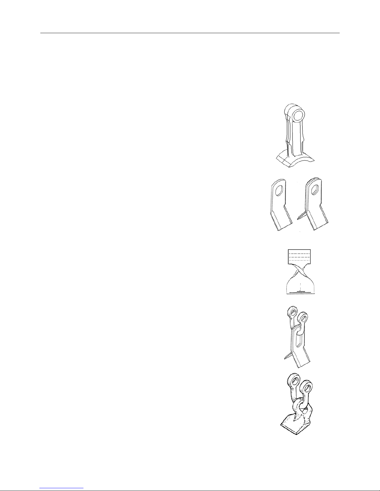
The cutting flail blades offered for your Twose machines are: -
a) Heavy, double edged design (one piece).
- For ‘Upward’ or ‘Downward’ cutting.
- Suitable for all types of conditions and growth.
b) Back to Back ‘rigid’ one piece blade (in pairs).
- For ‘Upward’ or ‘Downward’ cutting.
- Suitable for grass/mowing and trimming.
Illustration shows both a single blade and pair of blades back to back.
c) Heavy single edge blade flail (twisted pattern).
- Cuts one direction only.
- For grass cutting and hedge trimming.
d) Back to Back - on shackle (in pairs).
- For ‘Upward’ or ‘Downward’ cutting.
- Suitable for grass/mowing.
e) Boot flail - on shackle.
- Cuts one direction only.
- For grass cutting and hedge trimming.
Page 22

11
The cutter head design is of a ‘double skin’ construction for greater strength and longer
life. The drive is by means of ‘vee’ belts from the hydraulic motor to the rotor, with the
drive completely contained within the width of head for a cleaner cut.
Twin ‘vee’ belts take the drive from the motor to the rotor - giving a reliable drive with the
added benefit of anti-shock protection that a belt drive system provides.
A ‘swing link breakback’ system is built into the machine; this offers a degree of
protection to machine components if an obstruction is encountered during normal work.
Two parking stand legs are fitted to the machine, which once the machine has been
attached to the tractor should be folded away in the ‘stow’ position.
The machine has ‘angle head flotation’ as standard –this is engaged by moving the head
rotation lever beyond the normal actuation range into a detented ‘float’ position. ‘Lift
float’ is available as an option on the machine.
All machines have a relief valve in the primary ram system, this limits the pressure which
can be generated in the drop side of the cylinder – the cutting head cannot therefore be
‘driven’ into the ground in any circumstances.
Page 23
12
TRACTOR SELECTION
Tractor Specifications
TE480 – Tractor size must
be a minimum of 45kW (60 HP) – 3000kg
Tractors must be equipped with a power take off (PTO) shaft that must run at 450 rpm
during operation. The PTO shaft should run clockwise when viewed from the rear of the
tractor and ideally be of a 1⅜” S.A.E. – 6 spline shaft type to enable a standard PTO shaft
to be connected.
The tractor should have counterbalance weights (on approved mountings) fitted if
necessary and/or ballasted wheels to ensure stability of the unit at all times.
Stability may be further increased with a wider track setting on the tractors rear wheels –
contact your local dealer or tractor agent for specific advice on this subject.
Four wheel drive tractors have extra weight inbuilt plus larger front wheels, this is an
advantage in keeping the unit stable.
TRACTOR/OPERATOR GUARDING
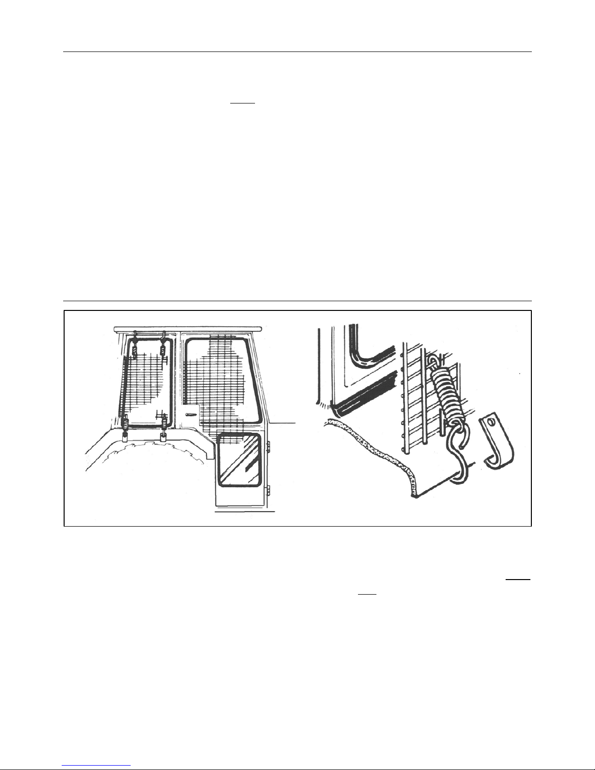
Use a tractor with ‘safety glass’ windows if possible and fit Operator guard (Part
No.7313324) using the hooks provided.
Shape ‘safety protection material’ to cover all vulnerable areas. Remember the driver must
be looking through ‘safety protection’ at the flail head in any
working position.
If the windows are not laminated safety glass polycarbonate glazing must also be fitted.
If the tractor has a roll bar only, a frame must be made to carry both mesh and
polycarbonate glazing.
Ensure the operator is guarded by ‘safety protection’ whatever position the machine is in
and that the protection is such that it does not interfere with tractor and machine functions
or obstruct the operator’s vision.
Page 24

13
HYDRAULIC OIL
IMPORTANT
The hydraulic system will have been 'run-up' and checked at the factory prior to the
machines despatch, where 'Texaco Rando 46' hydraulic oil is used - and is recommended
for the machine.
The hydraulic tank will have oil in it when delivered.
Oil tank capacity for the TE480 is 150 Litres
The user must ensure the hydraulic tank is full of 'RANDO 46' hydraulic oil (or an
equivalent recommended oil – refer to oil chart below) before attempting to start the
machine from new.
Recommended Oils
Manufacturer Cold or Temperate Climate Hot Climate
BP
Bartran 46
Energol HLP-HM 46
Bartran 68
Energol HLP-HM 68
CASTROL
Hyspin AWH-M 46 Hyspin AWH-M 68
COMMA
Hydraulic Oil LIC 15 Hydraulic Oil LIC 20
ELF
Hydrelf HV 46
Hydrelf XV 46
Hydrelf HV 68
ESSO
Univis N 46 Univis N 68
FUCHS
(UK/Non UK markets*)
Renolin 46
Renolin HVZ 46
Renolin CL46/B15*
Renolin AF46/ZAF46B*
Renolin 68
Renolin HVZ 68
Renolin CL68/B20*
Renolin AF68/ZAF68B*
GREENWAY
Excelpower HY 68 Excelpower HY 68
MILLERS
Millmax 46
Millmax HV 46
Millmax 68
Millmax HV 68
MORRIS
Liquimatic 5
Liquimatic HV 46
Triad 46
Liquimatic 6
Liquimatic HV 68
Triad 68
SHELL
Tellus 46
Tellus T46
Tellus 68
Tellus T68
TEXACO
RandoHD 46
Rando HDZ 46
Rando HD 68
Rando HDZ 68
TOTAL
Equivis ZS 46 Equivis ZS 68
The tank top filter/breather is equipped with a strainer to ensure all oil is strained when
being put into tank. The strainer basket - should never be removed, all hydraulic oil filling
is to be done through the strainer.
WARNING
Never mix hydraulic oils - if another supplier’s oil is to be used ensure it is suitably
compatible oil - Check with your oil supplier or machine manufacturer first.
Page 25
14
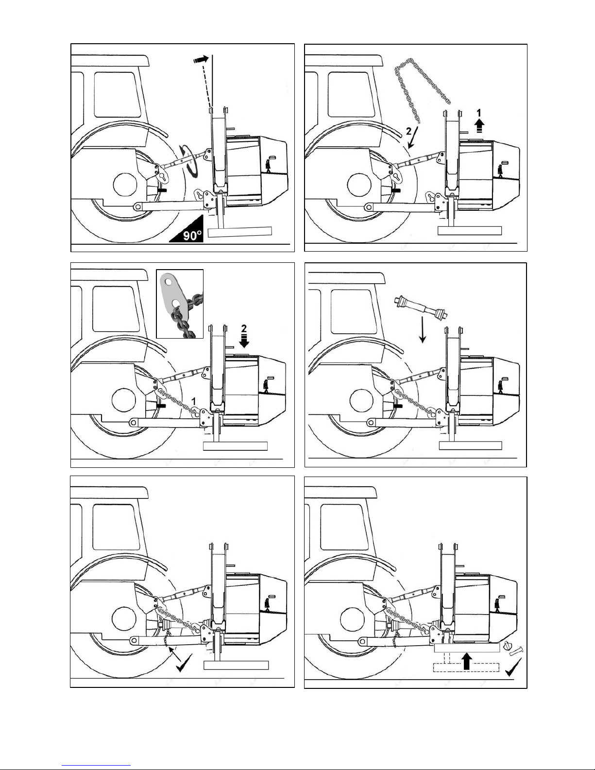
ATTACHING THE MACHINE – Chain Type Stabilizer
IMPORTANT: -
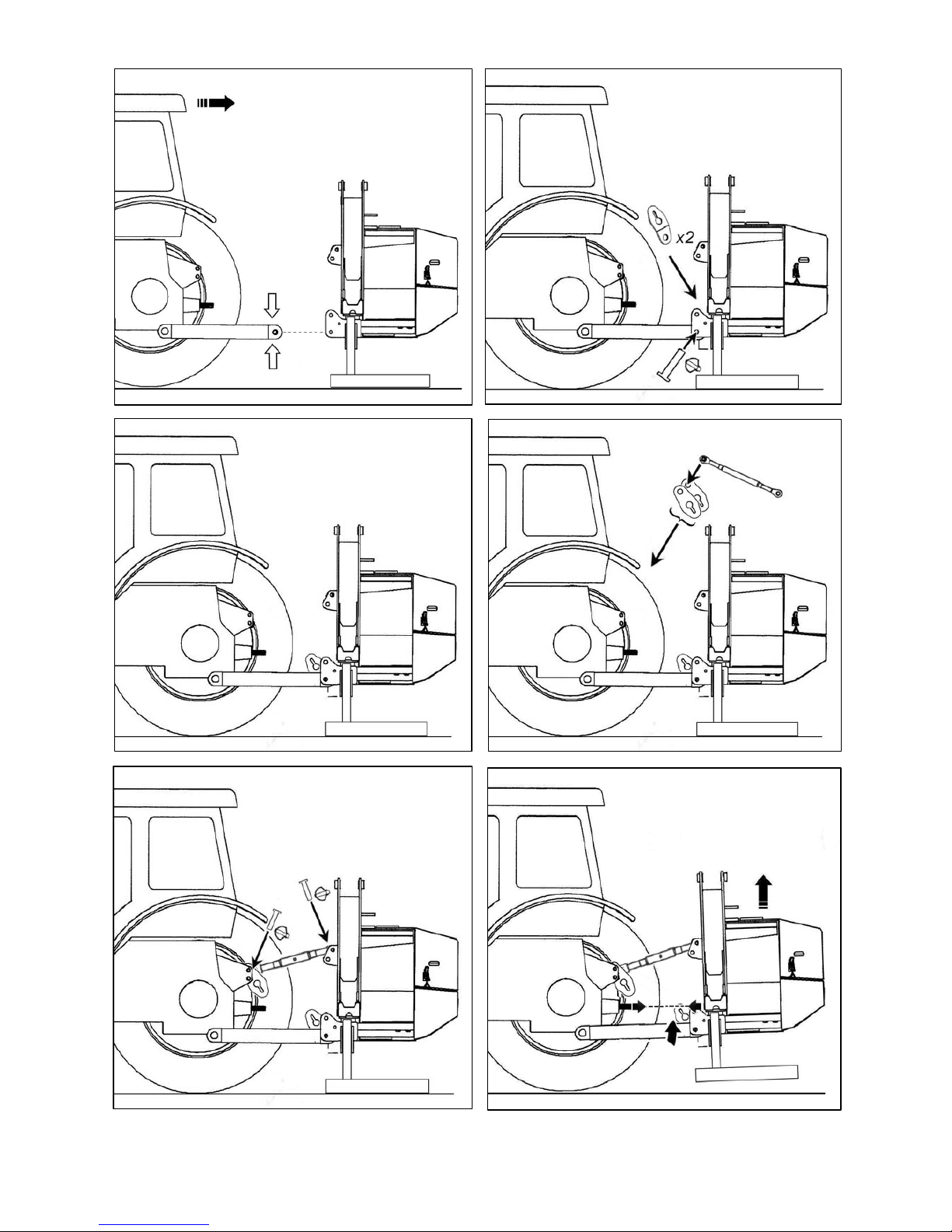
Attachment of the machine to the tractor should always be performed on a firm level site.
Remove locking pins and lift pins supplied with Hedge trimmer from lower link
positions of linkage frame.
Slowly and very carefully reverse the tractor towards the machine linkage frame.
With care - ensure that tractor lower link ball eyes fit between lower jaws of linkage
frame and that pin holes are aligned.
SWITCH OFF TRACTOR ENGINE AND ENSURE HANDBRAKE IS ON
With holes of tractor lower link eyes in line with lower jaw holes of frame - the lower
linkage pins should now be refitted – fit spacers if required to prevent side movement
of link arms.
Secure lift pins in position using locking pins.
Attach top link along with the upper stabilizer plates to the tractor selecting the highest
possible position avoiding any load sensing properties.
Connect top link to the machines top link point.
Raise the machine on the tractor’s linkage to a position where the stub shaft of the
tractors PTO drive and the stub shaft of the machine gearbox are horizontally aligned.
Note: As lift occurs be aware that the machine may tilt slightly.
Tractor lower linkage check chains or bars should now be tightened to ensure tractor
arms are locked and machine is positioned centrally to the tractor.
Adjust top link to bring the machine into the vertical position.
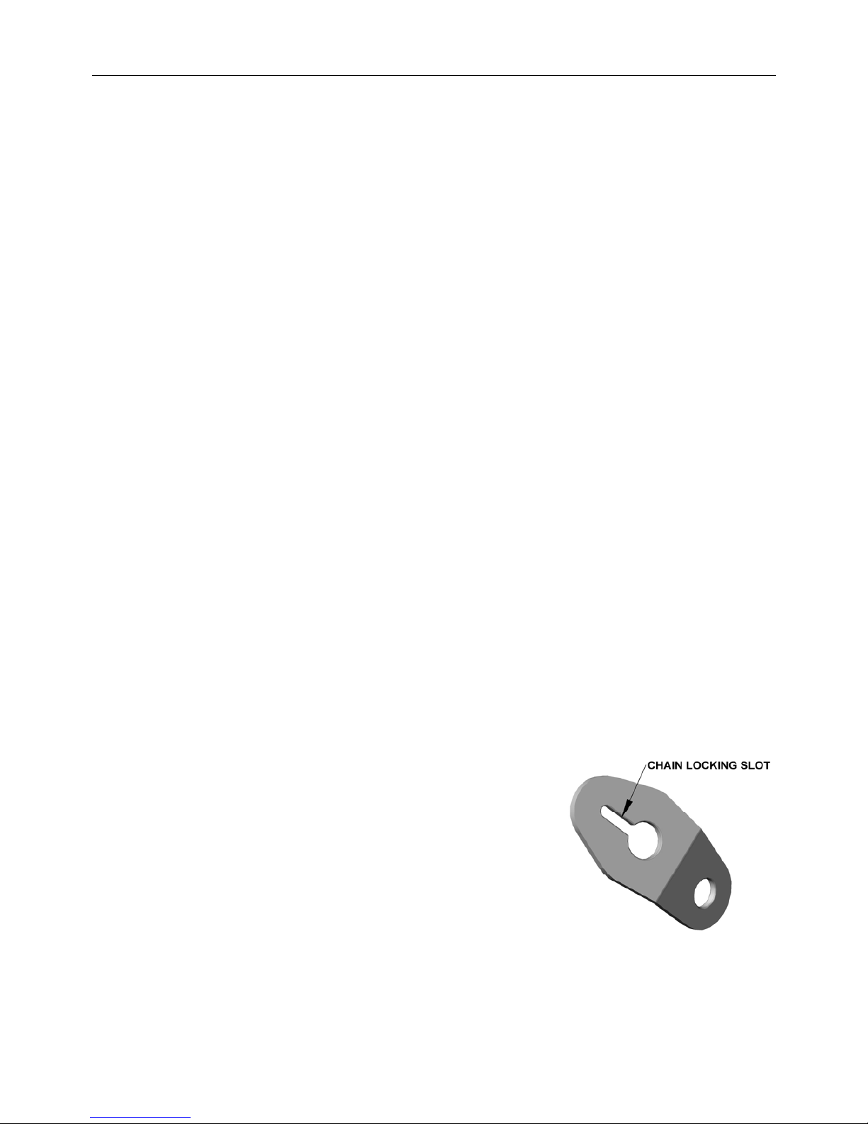
Thread stabilizer chain through the holes in both upper stabilizer plates leaving an
equal length of chain on each side.
Raise machine slightly and thread each end of the chain
through the holes of the stabilizer lower plates on both
sides – pull as tight as possible and lock in position in the
chain slot of the hole. Lower machine enough only to
exert tension on the chain.
Fit PTO shaft and attach guard chains to a suitable fixed
location – refer to link type stabilizer section for details of
the PTO measuring, cutting and fitting procedure.
Raise and secure the stand legs into the stowed position.
Fit operator safety guarding to tractor windows.
Lower Stabilizer Plate
Page 26
15
1.
2.
3.
4.
5. 6.
Page 27
16
7.
8.
9. 10.
11.
12.
Page 28
17
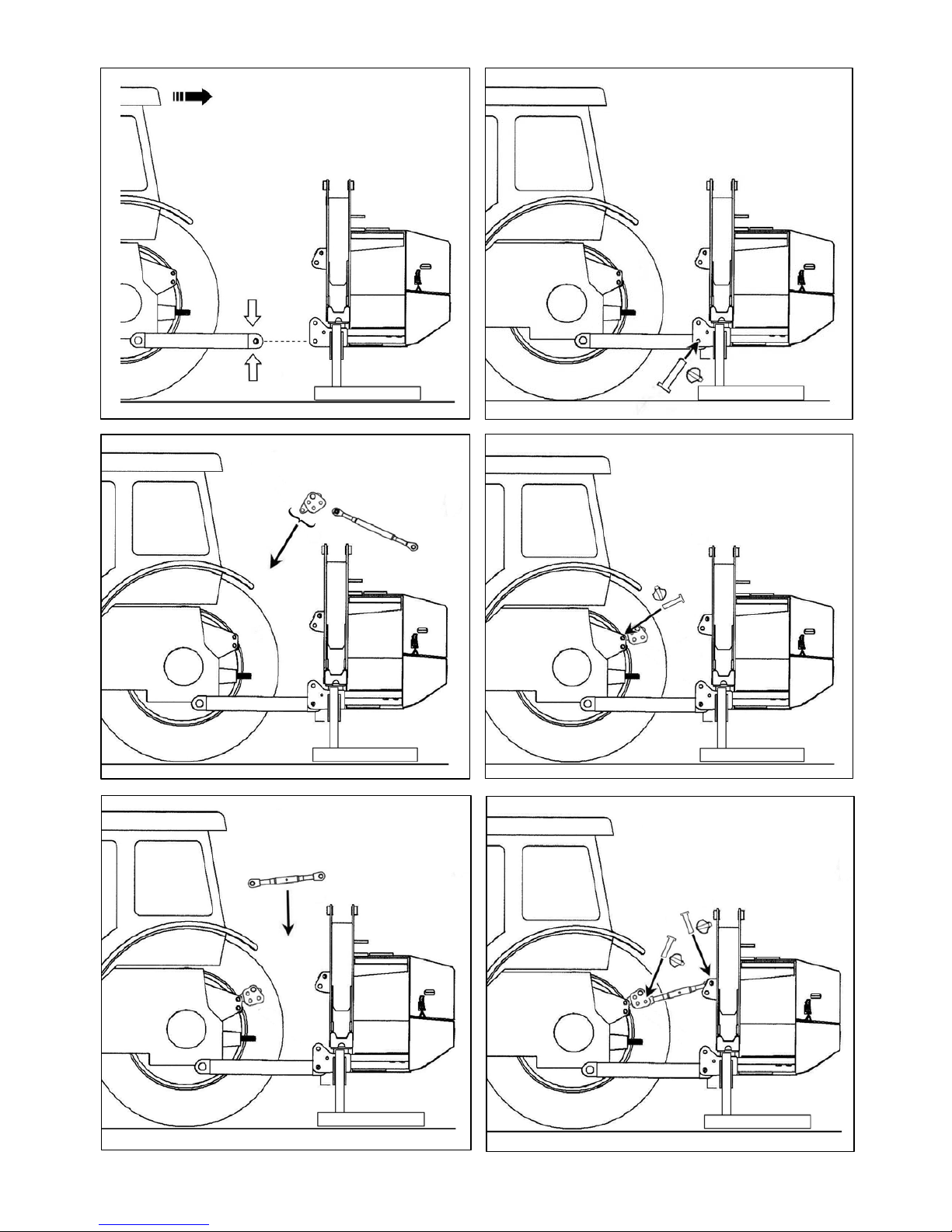
ATTACHING THE MACHINE – Link Type Stabilizer
IMPORTANT: -
Attachment of the machine to the tractor should always be performed on a firm level site.
Remove locking pins and lift pins supplied with Hedge trimmer from lower link
positions of linkage frame.
Slowly and very carefully reverse the tractor towards the machine linkage frame.
With care - ensure that tractor lower link ball eyes fit between lower jaws of linkage
frame and that pin holes are aligned.
SWITCH OFF TRACTOR ENGINE AND ENSURE HANDBRAKE IS ON
With holes of tractor lower link eyes in line with lower jaw holes of frame - the lower
linkage pins should now be refitted – fit spacers if required to prevent side movement
of link arms.
Secure lift pins in position using locking pins.
Fit and secure the stabiliser’s top link yoke to the tractor’s top link - select the highest
available position avoiding any load sensing properties.
Attach top link to machines top link point.
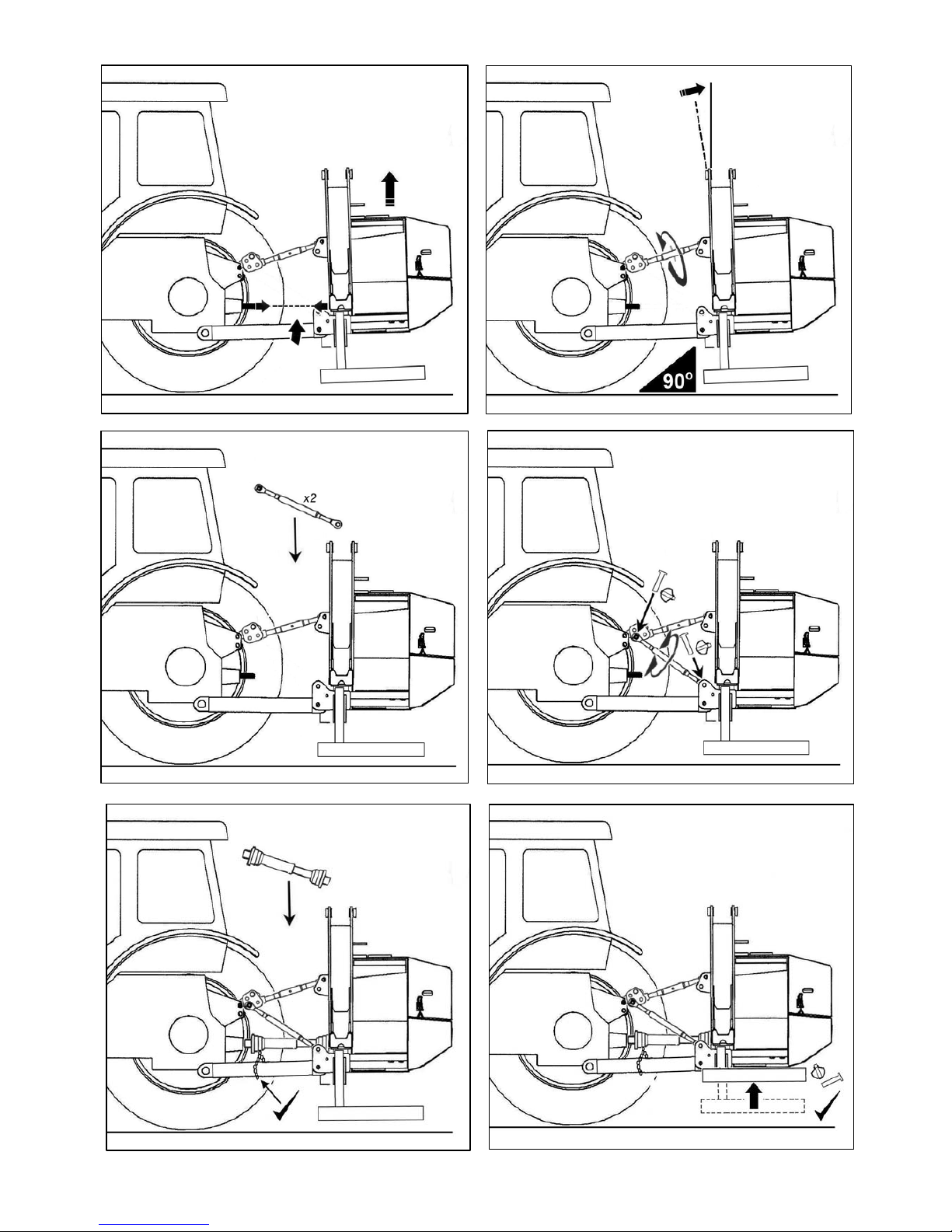
Raise the machine on the tractor’s linkage to a position where the stub shaft of the
tractors PTO drive and the stub shaft of the machine gearbox are horizontally aligned.
Note: As lift occurs be aware that the machine may tilt slightly.
Tractor lower linkage check chains should now be tightened to ensure tractor arms are
locked and machine is positioned centrally to the tractor.
Adjust top link to bring the machine into the vertical position.
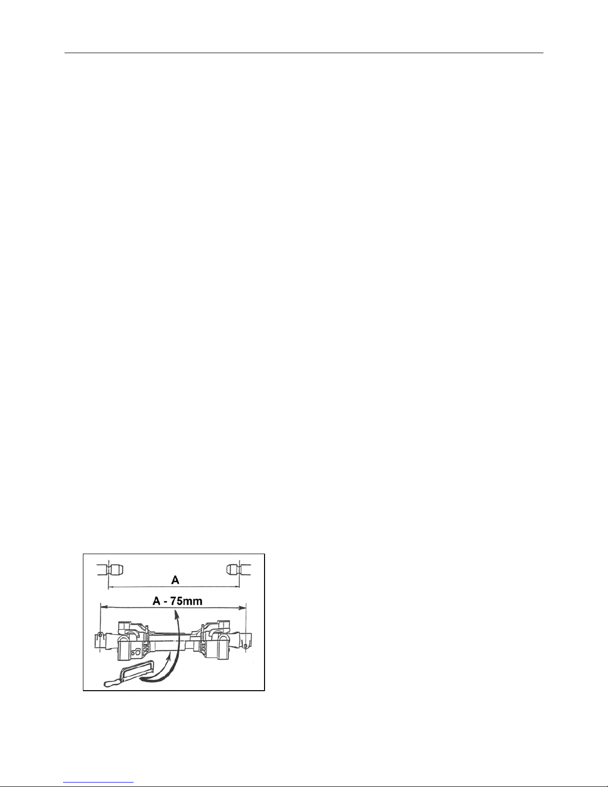
Check the PTO shaft length.
When connected from tractor to machine it should engage by 1/3rd of the total shaft
length, i.e. male part should be halfway from the end to fully ‘bottomed’ out. Do not
use the machine until this has been cut to the correct length.
Measure the PTO shaft and cut to the dimension
shown – the finished length of the PTO shaft
should be 75mm (3”) less than the measured
distance ‘A’ -between tractor shaft and gearbox
stub shaft – to enable fitting.
NOTE:
For subsequent use with different tractors measure
again, there must be a minimum shaft overlap of
150mm (6”).
Page 29

18
Fit the PTO shaft.
Ensure the shaft is correctly fitted to the splines at both ends.
Fit the anti-spin chains of the PTO guard to a suitable rigid non-turning location.
Raise stand legs into their stowage position and secure with locking pins.
Fit mesh safety screens - they are designed to be fitted to the cutting head side of
tractor cab (i.e. for left-hand cut machines to left-hand side of cab). Secure in position
using the fixings provided ensuring that all exposed glass areas on the cutting side of
the tractor are fully protected. All glass screens on the relevant side of cab must be
protected.
Fix valve control handles into position:-
Control levers are supplied bolted together as a complete unit along with a mounting
bracket for attachment within the tractor - the number of controllers in the set can vary
dependent on the particular model or specification machine. The mounting bracket
should be positioned on the inner wing face of the tractor cab in a suitable position for
ease of operation.
It is suggested that for three and four bank controller sets the bracket is fitted to the
left-hand wing for left-hand cut machines and right-hand wing for right- hand cut
machines. In the case of electric machines with a single-bank rotor controller is
required it is suggested that the bracket is fitted to the opposite side for the control of
the cutting direction and that the joystick mounting bracket is fitted to the cutting side both brackets are however the same.
Page 30
19
1.
2.
3. 4.
5.
6.
Page 31
20
8.
9.
11.
12.
7.
10.
Page 32
21
FLAIL TRIMMER- OPERATION INFORMATION
The vehicle driver should be conversant with all tractor controls and capabilities.
It is always advisable for the tractor driver to practice the controls and operations of the
Flail Trimmer, in a safe open location away from potential hazards, prior to setting off into
work.
The speed of operation of Trimming will depend on the size, quantity, and type of growth
to be cut. A slow speed to suit conditions should be selected, ensuring that engine speed
gives a P.T.O speed of 540 Max. R.P.M for general use - this 540 Max. R.P.M (PTO) is
recommended for best trimming results and performance, variation from this
recommended R.P.M should be kept to a minimum and never at any time should PTO
R.P.M exceed 540 R.P.M.
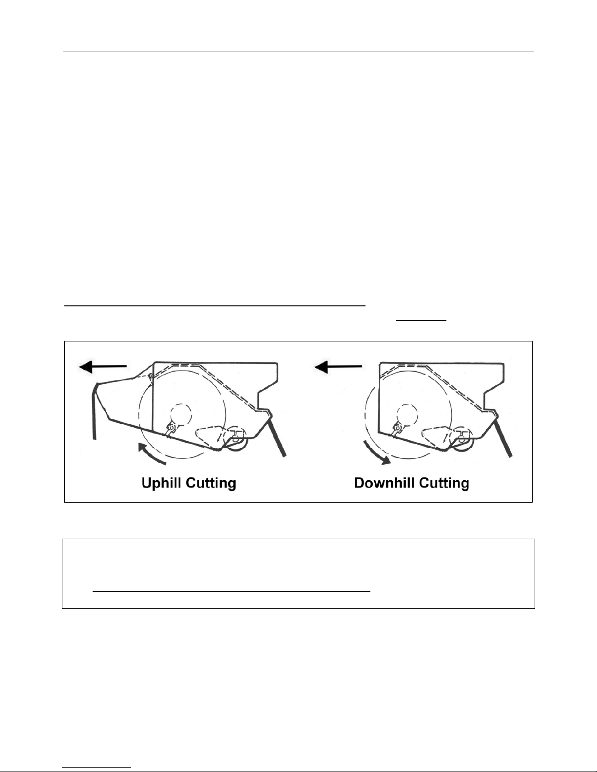
ROTOR ROTATION DIRECTION
Depending on the type of hedge to be cut, an option of rotation direction is offered.
The 'upward' cut is recommended for trimming grass, light growth such as one/two year’s
growth.
DOWNWARD CUTTING IS NOT RECOMMENDED - and should only be considered
for really heavy, large diameter, growth cutting - even then, it is important
that down
cutting is kept to the minimum, very short periods, only.
DANGER - IMPORTANT
In heavy conditions when cutting large diameter growth with front cowling removed, the
rotor MUST ALWAYS CUT DOWNWARDS AT FRONT. At no time should the rotor
be cutting upwards with the front cowling removed.
Page 33
22
DANGER VERY IMPORTANT
It is very important that motor spool and motor spool control lever works in one
direction only - From centre (OFF) position to selected (ON) 'rotor cut' direction
position – permitting the rotor one direction of cut and the 'OFF' setting only.
This eliminates the chance of going from ‘cut-up’ to ‘cut-down’ in one movement
of controls and blowing the system. Only by altering LOCK-LEVER setting can
direction of control lever be changed.
WARNING
DANGER - NEVER CHANGE DIRECTION OF ROTOR CUT WHILST ROTOR
IS STILL TURNING.
DANGER - ALWAYS ALLOW ROTOR TO STOP SPINNING COMPLETELY
BEFORE CHANGING CUT ROTATION DIRECTION.
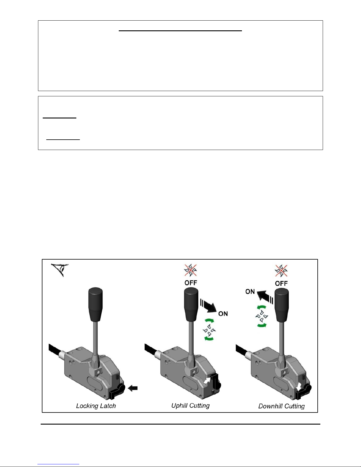
ROTOR CONTROL OPERATION
The rotor control lever operates the rotor ‘on’ and ‘off’ function for both uphill and
downhill cutting - the specific cutting direction is dictated by the position of the locking
latch on the front of the cable control head unit, with the latch in the vertical position the
lever can be moved from its centre ‘off’ position to the forwards ‘on’ position for uphill
cutting direction. With the latch in the horizontal position the lever can be moved from its
centre ‘off’ position to the backwards ‘on’ position for downhill cutting direction. The
rotor is off when the control lever is in the central position – see illustration below.
WARNING: When switching off a rotor it will continue to ‘freewheel’ before stopping - in
some cases this can be up to 40 seconds or more. Never approach a machine whilst the rotor
is running.
ROTOR CUT DIRECTION MUST NEVER BE CHANGED IN ONE MOVEMENT
Page 34
23
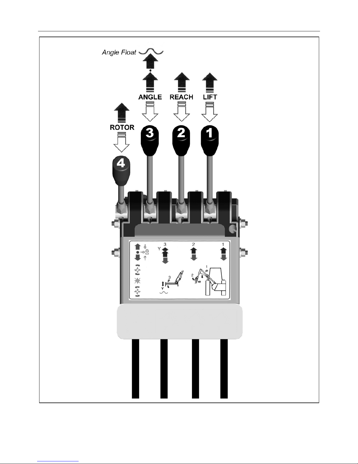
CABLE CONTROLS
Page 35
24
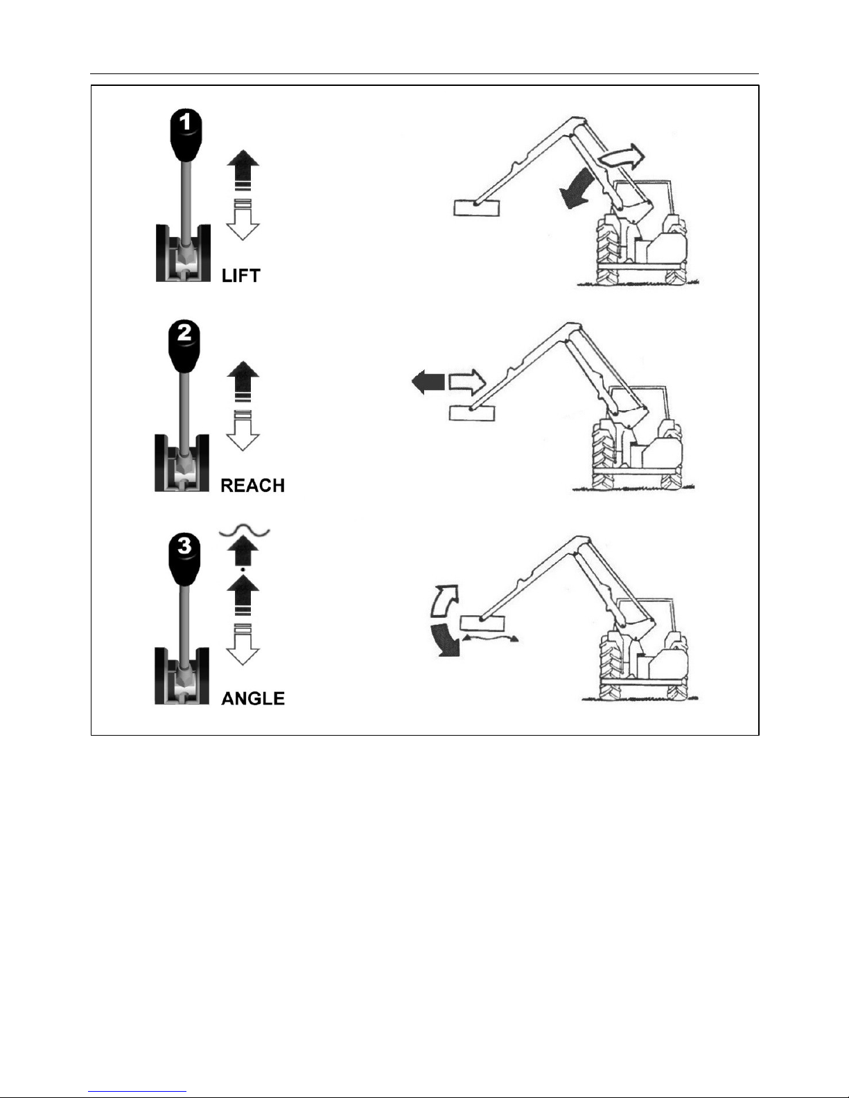
CABLE CONTROLS – LEVER FUNCTIONS
Page 36

25
HYDRAULIC CONTROLS - CUTTING POSITION
The cutting head must at all times be lowered gently into the cutting position. Never ‘drop’
a flailhead into a hedge at speed.
When cutting at ground level (grass etc.) the head must be lowered gently to give a slight
contact pressure of roller to ground.
WARNING:
Ensure flailhead does not come into contact with obstacles such as rocks, stones, stumps
etc. Keep rotor away and free from wire, as to entangle wire in a rotor is both dangerous
and costly.
Should large obstacles be encountered or wire become entangled in the rotor stop
immediately and reset or clear before continuing.
DANGER WARNING
Always stop machine, switch off engine and pocket the key before
attempting to remove any items that foul the flailhead.
Normal obstacles and level variations should be overcome by the operator slowing
'forward motion' and raising/lowering the booms of trimmers to suit.
CUTTING HEAD
The cutting head rotor has been balanced prior to fitting; this will ensure a vibration free
cutting unit.
Should the rotor become blocked for any reason, hit an obstacle, loose a blade or blades,
the rotor may be put into a state of unbalance. This will result in vibration from the rotor
being transmitted through the head. Should this happen stop immediately, as to continue
may have serious consequences.
Once stopped clean rotor and check for loss of blades and bolts, replace as required.
As a result of hitting solid objects with serious force the rotor can be bent, this will
obviously cause vibrations. In such cases the only answer will be to get the rotor
repaired/rebalanced or replaced.
Keep the cutting blades VERY SHARP: the flailhead should be inspected daily. Bolts and
nuts holding flails to rotor should be checked frequently and kept tight. Missing or broken
flails should be replaced immediately, as the imbalance will rapidly harm bearings and
structure. When a flail is renewed its opposing flail (or pair if using Back to Back flails)
should be renewed also in order to maintain balance.
Check ‘vee’ belt tension on cutter head daily: a load of 5 Kgs (10 lbs.) should give a
deflection of 9mm at these pulley centres. Access to the belts is by removing the guard
panel on the side of the drive end. Tension is adjusted by first slackening the bolts
mounting the motor (nuts are held from turning on the inside). The nuts on the threaded
adjuster can now be turned to give the required tension and then re-tightened and the
motor mounting bolts then tightened also.
Page 37

26
TRANSPORTATION
For transport the machine should be ‘folded’ into a position that is as compact as possible
within the confines of the tractor width. The cutting head should be placed into the vertical
position with the flails outwards ensuring sufficient clearance of the tractor wheel to avoid
possible contact or fouling during transportation.
WARNING
Never transport a machine with the Booms open -
Ensure Booms are in contact with each other at all times.
Page 38
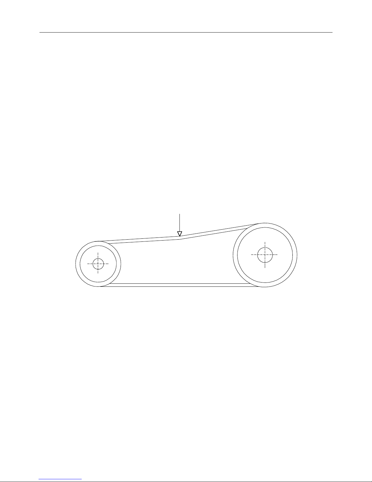
27
Rotor Pulley
Motor Pu lley
Correct Belt Tension
11 lbs (50nm) load - 9mm deflection
CUTTING HEAD ‘VEE’ BELT ADJUSTMENT
To adjust the cutting head ‘vee’ belts the following procedure should be followed: -
Position the cutting head on the ground in a safe level location with the drive end
uppermost.
Switch off the tractor engine, remove and pocket the key.
Remove bolt securing the ‘flap-door’ of the drive end, this will release the guard flap
panel.
Open upper guard/inspection panel.
Slacken the 2 bolts holding hydraulic motor to its mounting plate.
Adjust belt tension by turning the nuts on the tensioning screw
– clockwise will tighten the belt, anti-clockwise will slacken the belt.
When the correct belt tension is achieved (refer to diagram below) the 2 adjustable nuts
on the tensioner screw must be locked tight and the 2 bolts securing the motor to the
head re-tightened to lock the whole unit into position.
Re-check tensions when all bolts have been tightened.
Close flap door and secure with bolt.
NOTE: Check belt tension on a weekly basis.
Page 39
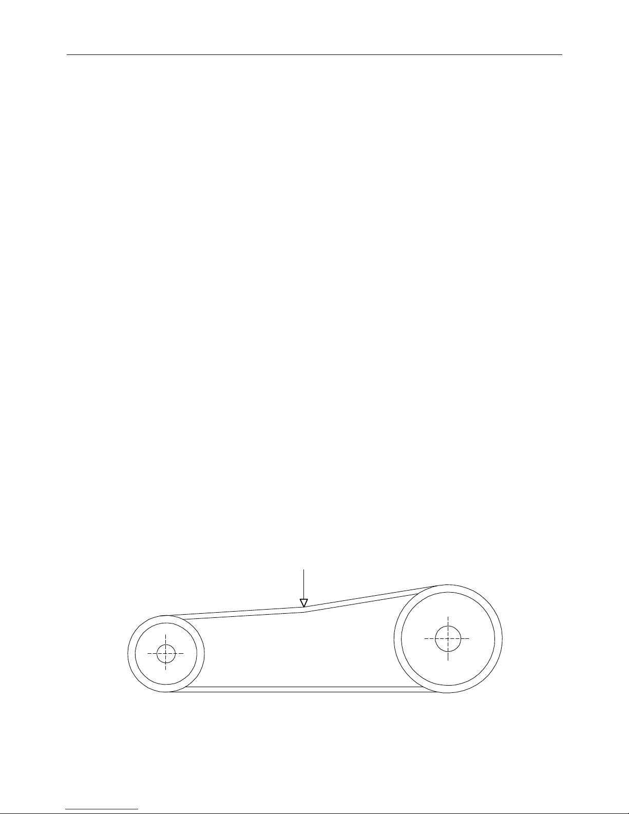
28
Rotor Pulley
Motor Pu lley
Correct Belt Tension
11 lbs (50nm) load - 9mm deflection
CUTTING HEAD ‘VEE’ BELT REPLACEMENT
To replace the cutting head ‘vee’ belts the following procedure should be followed: -
Hydraulically position cutting head to stand vertically on the ground with the drive end
uppermost - this should be done on a firm and level location to ensure the cutting head
is steady and safe in this position.
Stop tractor engine, remove and pocket the key.
Slacken off the motor mounting bolts and nuts on the threaded adjuster arm to release
the belt tension.
Undo completely, and remove, the 6 bolts that attach the main cover plate to the head.
Undo, and remove, the 6 M12 x 20 setscrews that hold the bearing housing to the cover
plate.
Remove the cover plate from its bolted position.
The drive belts can now be removed from around the pair of ‘vee’ pulleys.
New belts can now be fitted – position each belt in the respective ‘vee’s’ on both the
driven and the driver pulleys.
Replace the main cover plate assembly over the drive belt aperture.
Replace the 6 M12 x 20 setscrews through the plate and into the bearing housing.
Ensure all 6 screws are aligned correctly and tightened sufficient only to hold the
bearing housing in place. DO NOT TIGHTEN FULLY.
Replace all of the M12 x 80 bolts through the cover panel from the panel side –
ensuring first that the holes align – and place the ‘nyloc’ stiffnuts onto each bolt.
With all mounting bolts of both bearing to panel, and panel to head now in position all
12 bolts should be tightened until fully dead tight.
Belts should now be adjusted to the correct tension as per the diagram below – refer to
belt adjustment section for details.
When belts have been tensioned correctly and all covers replaced, the machine is ready
for start up.
Page 40

29
ROTOR REMOVAL & REPLACEMENT
Removal procedure:
With the machine attached to the tractor, hydraulically position the cutting head
vertically with the drive end downwards resting on the ground – select a firm level
location and ensure the weight of the head is fully rested on the ground.
Switch off tractor engine, remove and pocket the key.
Slacken off and remove the 2 nuts and bolts securing the bearing housing to the flail
head main frame at the non-drive end.
Remove the 4 M12 x 35 setscrews from the drive end (inside shell) - rotor to pulley.
The whole rotor assembly should now be raised vertically a sufficient amount to allow
the drive end location flange to free itself from the locating dowel on the rotor drive
pulley.
With the rotor raised and free of the drive pulley, the drive end of the rotor can be
swung gently out of its drive line position in a downward direction relative to the head.
With drive end of rotor swung towards base of head the rotor can now be gently
lowered to allow non-drive end of rotor, complete with bearing/housing attached, to
drop out of main frame and removed.
Replacement procedure:
Position flail head as described for removal procedure – see above.
Position rotor vertically with the drive flange end downwards and gently swing in the
upper (non-drive end) towards its location position – this operation is to be carried out
from the base face of the head.
Locate non-drive end of the rotor up through the head end panel – at the same time as
raising and locating the non-drive end of the rotor the lower drive end should be swung
into its drive-line position.
Ensure lower end of rotor (drive flange) is positioned to register with the locating
dowel of the drive pulley. Lower rotor onto dowel to locate with the flange making sure
both faces seat together correctly.
Replace the 4 M12 x 35 setscrews to fix the rotor drive flange to the drive pulley and
tighten fully. The drive end of the rotor is now connected.
The upper end of the rotor (bearing housing) is now free/slack. The nuts and bolts for
the bearing location should now be fully tightened to complete the rotor fixing.
Spin the rotor by hand to ensure free, uninterrupted motion.
NOTE: Rotor mounting bolts should be checked daily to ensure they remain tight.
Page 41
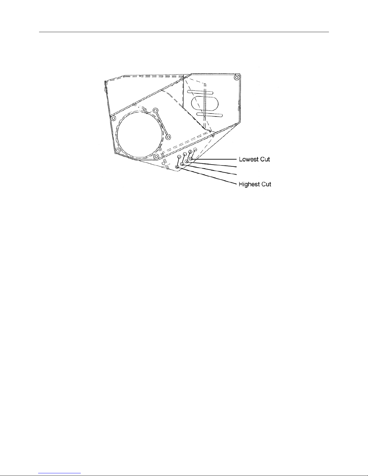
30
ROLLER HEIGHT ADJUSTMENT
The cutting height of the flail head may be adjusted to cut at 4 different heights; this is
achieved by altering the mounting position of the roller on the flail head - refer to diagram
below.
To alter the roller position, each end bracket of the roller and the relative securing bolts
will need to be positioned at either of the four position height options offered. Ensure that
same opposing location holes on the flail head are chosen.
NOTE:
The flail head roller is generally required only when bank or verge mowing and not when
hedgetrimming.
Page 42

31
REMOVING THE MACHINE FROM THE TRACTOR
Select a good clear, level and firm site on which to detach and store the machine.
IMPORTANT
Use the hydraulics to lower the head onto the ground horizontally (as if you were cutting
grass).
Disengage the PTO drive.
STOP THE TRACTOR ENGINE.
Lower stand legs from their stowed position and place into the 'down' position – fit pins
and secure with the lynch pins provided.
LINK TYPE STABILIZER: Remove lynch pins from the stabiliser locating pins, and
remove pins. It may be necessary to slightly raise three-point linkage to 'free' pins, for
removal.
CHAIN TYPE STABILIZER: Raise machine until chain becomes slack, remove chain
from locking slots in lower stabilizer plates.
Lower hedgetrimmer so stand legs are on the floor, by means of lowering tractor three-
point linkage. (Top link may have to be adjusted to ensure trimmer is upright and safe).
When you are sure that trimmer is properly settled and safe on its stands, operate boom
'1' lever to release hydraulic pressure from ram.
Disconnect controls from tractor cab and stow neatly on the machine clear of the
ground protected from the elements.
Disconnect Power Take off shaft and anti-spin chains (tractor end).
Remove lynch pins from lower lift pins and remove pins from linkage - tractor linkage
arms are now free of the machine.
Draw tractor slowly away - Many operators stop about 300mm (12") away to double-
check that tractor and machine have completely separated and that no connections or
couplings remain connected.
Safety screens can now be removed if so desired.
Replace location pins back through arms of stabiliser assembly and secure in position
with lynch pins.
Re-connect top link bar assembly back onto stabiliser with pin and lynch pin provided.
Replace lower linkage pins back into relevant positions on mounting frame and secure
with lynch pins.
Ensure tractor top link pin is replaced and secured with lynch pin.
Page 43
32
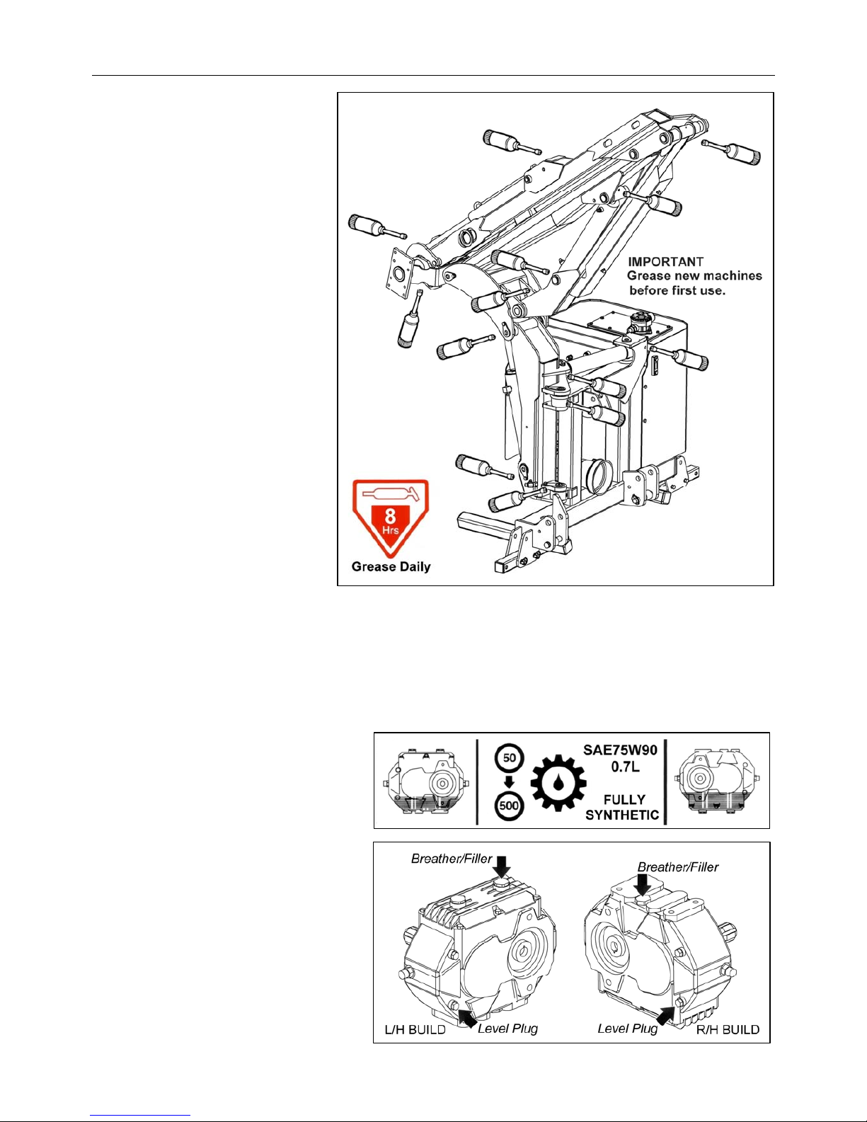
GENERAL MAINTENANCE
General Lubrication
The example illustration
opposite indicates the general
locations of lubrication points
- all points should be greased
on a daily basis and prior
storage of the machine. New
machines must be greased
prior to first use.
Gearbox Lubrication
Check gearbox oil level on new machines prior to first use, top up if required before using
the machine. Change oil after an initial 50 hours of use and thereafter at annual or 500
hour intervals, whichever occurs earliest.
Gearbox Capacity:
0.7 Litre SAE75W90 Fully Synthetic which meets the following minimum requirements;
Viscosity at 40°C, cSt, 100.0 min.
Viscosity at 100°C, cSt, 17.2 min.
Replacing Gearbox Oil
Drainage of the gearbox for
changes of oil is via the drain plug
located on the base of the gearbox.
For refilling or for ‘topping up’ the
oil remove both plugs indicated
opposite and fill gearbox via the
filler plug to a point where the oil
starts to run from the level plug
orifice – replace plugs and tighten
securely.
Page 44
33
SERVICE SCHEDULE
Every Day
Grease machine fully prior to work (and prior to storage).
NOTE: New machines must
be greased before initial use.
Check for broken or damaged flails.
Check tightness of flail nuts and bolts.
Visually check for oil leaks and damaged hoses.
Check all guards and safety shields are correctly fitted and undamaged.
Ensure all lights are working and clean.
Check oil level.
Clean the cooler matrix, in dusty conditions more frequent cleaning is required.
After initial 12 Hours
Change return line filter element. Failure to do so will invalidate the warranty.
Note; factory fitted filter elements are identified differently to replacement elements.
After initial 50 Hours
Change gearbox oil.
Every 25 Hours
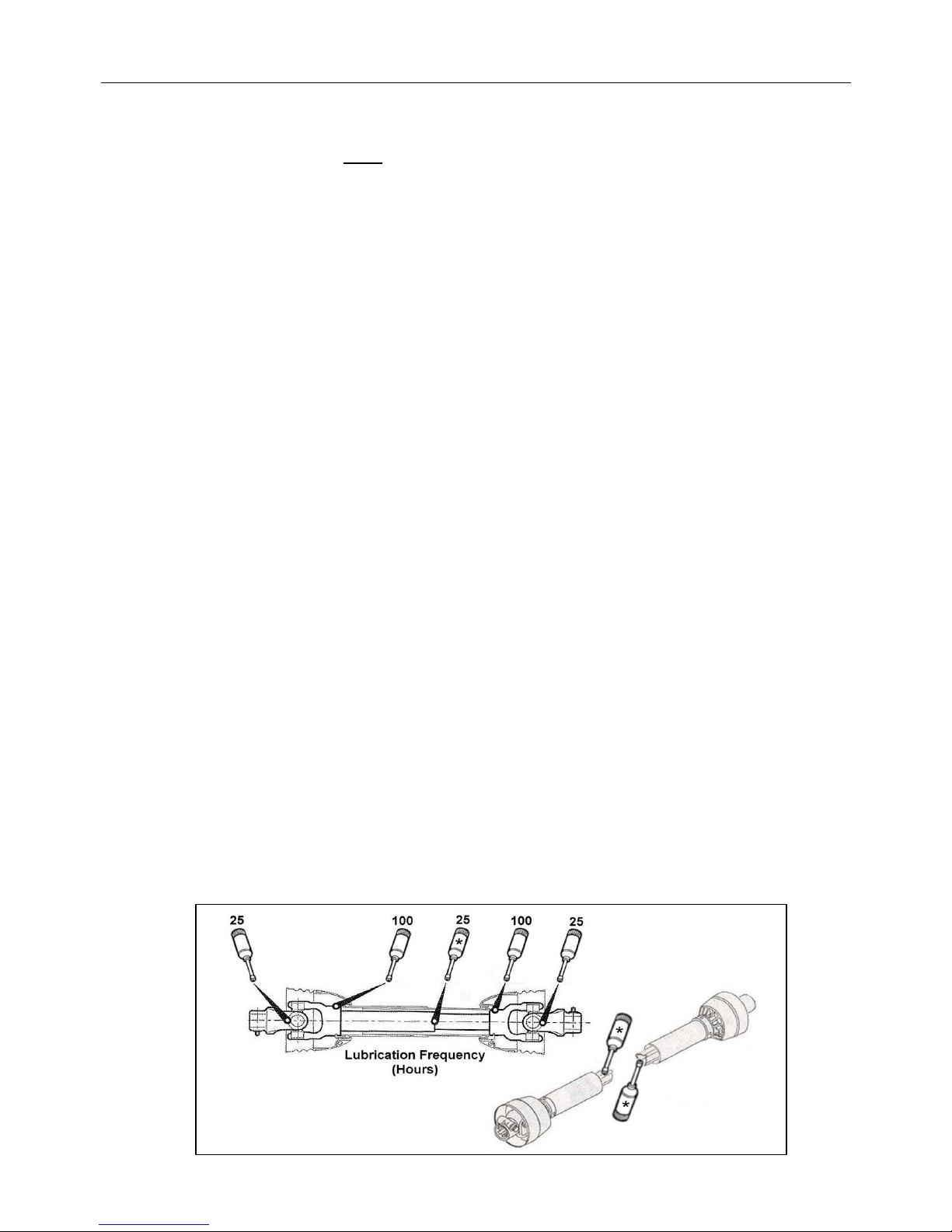
Grease PTO Shaft universal joints and tubes.
Every Week
Check tightness/tension of nuts, bolts and belts.
Check gearbox oil level.
Check for wear on telescopic arm pads – where applicable.
Every 100 Hours
Grease PTO shaft shield lubrication points.
Every 500 Hours
Change return line filter element.
Change gearbox oil.
Check condition of hydraulic oil and change if required; when changing oil new
return line filter and suction strainer elements should be fitted and return line filter
changed again after 12 hours of work.
Annually
Change tank breather.
PTO Shaft Lubrication
Page 45
34
HYDRAULIC SYSTEM
Oil Supply
Check the oil level in the reservoir daily.
Oil Condition & Replacement
No fixed time period can be quoted for oil changes as operating conditions can vary
widely but a visually inspection of the oil will often indicate its current overall state. Signs
of a reduction in its condition will be apparent by changes in colour and appearance when
compared to new oil. Oil in poor condition can be dark, smell rancid or burnt, or in some
cases be yellow, unclear or milky in appearance indicating the presence of air or
emulsified water. Moisture resulting from condensation can become entrapped in the oil
causing emulsification that can block the return line filter, consequentially the filter system
will be by-passed and the oil and any possible contaminants present will continue to
circulate without filtration risking damage to hydraulic components. All are indications or
conditions that will require replacement of the oil.
Hydraulic oil is a vital component of the machine; contaminated oil is the root cause of
70% of all hydraulic system failures. Contamination can be reduced by the following:
Cleaning around the reservoir cap before removal and keeping the tank area clean.
Use of clean containers when replenishing the system.
Regular servicing of the filtration system.
Filtration System
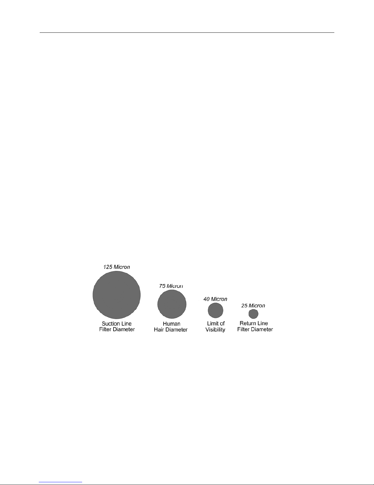
Machines are protected by both replaceable 125 micron suction strainers and low pressure
25 micron full flow return line filters – the diagram below is a ‘scaled up’ view illustrating
the filtering capability built into the hydraulic system of the machine:
Suction strainers
The replaceable 125 micron suction strainers are fitted within the hydraulic tank and are
‘screw’ fitted with easy access for removal and replacement.
Return Line Filter
The 25 micron absolute filter elements should be changed after the first 12 hours and
thereafter at 500-hour intervals. It is important to note hours worked as if the filter
becomes blocked an internal by-pass within the canister will operate and no symptoms of
filter malfunction will occur to jog your memory.
Tank Breather
To reduce the risk of pump cavitation it is advisable to replace the 25 micron absolute tank
breather on an annual basis under normal working conditions – for machines operating in
dry dusty environments it is recommended that replacement be increased to 6 monthly.
Filtering Capability
Page 46

35
HYDRAULIC HOSES
The condition of all hoses should be carefully checked during routine service of the
machine. Hoses that have been chaffed or damaged on their outer casing should be
securely wrapped with waterproof adhesive tape to stop the metal braid from rusting.
Hoses that have suffered damage to the metal braid should be changed at the earliest
opportunity.
Hose Replacement
Before changing any hoses take the time to study the existing installation as the routing
has been carefully calculated to prevent hose damage during operation - always replace
hoses in exactly the same location and manner. This is especially important for the flail
hoses where they must be crossed, upper to lower, at the dipper and head pivots.
Always replace one hose at a time to avoid the risk of wrong connections.
When the hose is screwed to an additional fitting or union, use a second spanner on the
union to avoid breaking both seals.
Do not use jointing compound on the threads.
Avoid twisting the hose. Adjust the hose line to ensure freedom from rubbing or
trapping before tightening hose end connections.
All Hydraulic Hoses (BSP) fitted to Twose Hedgecutters have ‘soft seal’ connections on
both flail and ram circuit hoses.
Recommended torque settings for nut security are as follows:
For hose unions (BSP) fitted in conjunction with bonded seals the recommended torque
settings are as follows:
Safety Note:
Soft seal hose connections are capable of holding pressure when the nut is only ‘finger
tight’. It is therefore recommended during dismantling that the hose be manually flexed to
relieve any residual pressure with the retaining nut slackened prior to complete
disassembly.
SIZE TORQUE SETTING O Ring Ref.
1/4” BSP = 24 Nm or 18 lb.ft. 10 000 01
3/8” BSP = 33 Nm or
24 lb.ft.
10 000 02
1/2” BSP = 44 Nm or
35 lb.ft.
10 000 03
5/8“ BSP = 58 Nm or
43 lb.ft.
10 000 04
3/4“ BSP = 84 Nm or
62 lb.ft.
10 000 05
1” BSP = 115 Nm or
85 lb.ft.
10 000 06
SIZE TORQUE SETTING
1/4” BSP = 34 Nm or 25 lb.ft.
3/8” BSP = 75 Nm or
55 lb.ft.
1/2” BSP = 102 Nm or
75 lb.ft.
5/8“ BSP = 122 Nm or
90 lb.ft.
3/4“ BSP = 183 Nm or
135 lb.ft.
1” BSP = 203 Nm or
150 lb.ft.
Page 47

36
CONTROL CABLES
The control cables operate on a push/pull system with the spool centring springs always
returning the spool to the neutral position when the handle is released.
Care should be taken during installation and operation to ensure that the cables are not
trapped or kinked. Any abrasion or damage to the outer casing should be sealed with
plastic insulation tape to avoid moisture penetrating.
No routine adjustments of the cables are necessary, as they do not stretch. The threaded
collar is correctly adjusted when the lever is in a vertical position in its housing allowing
an equal amount of travel in either direction.
CAUTION
On no account should any attempt be made to lubricate the cables – these are assembled with a
special ‘lifelong’ lubricant during manufacture and will not require any additional lubrication.
Note: Take care to ascertain the correct cable connections on both the control unit and the
valve in the event of cable replacement.
Page 48
37
PTO SHAFT MAINTENANCE
PTO Shaft Lubrication
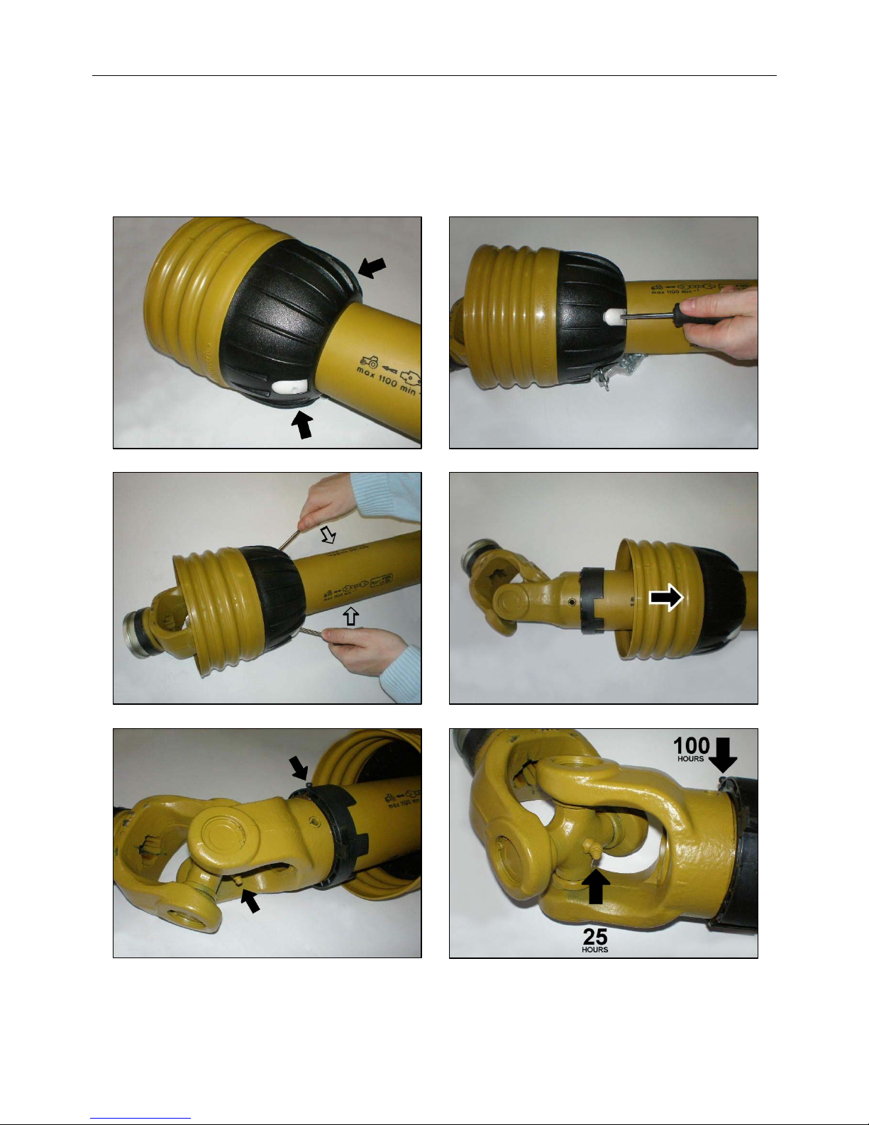
The PTO shaft should be lubricated on a regular basis using lithium based grease – each
end of the shaft has 2 greasing points; one for lubrication of the universal joint and one for
lubricating the rotating fixing ring of the shaft shield – access to the lubrication points is
gained by releasing the shaft shield from its fixing ring and sliding it back along the body
of the driveshaft as shown below.
Slide the shaft shield back into place after lubrication ensuring the clasps relocate correctly
in the fixing ring – always fit torque chains to the shields to stop them from rotating with
the shaft during operation.
Shaft shield fixing clasps Insert screwdrivers into the clasps
Prise clasps open to release the shield Slide shield back to reveal universal joint
Universal Joint
Lubrication Point
PTO Shaft Shield
Lubrication Point
Location of lubrication points
Recommended lubricating frequency
Page 49
38
TORQUE SETTINGS FOR FASTENERS
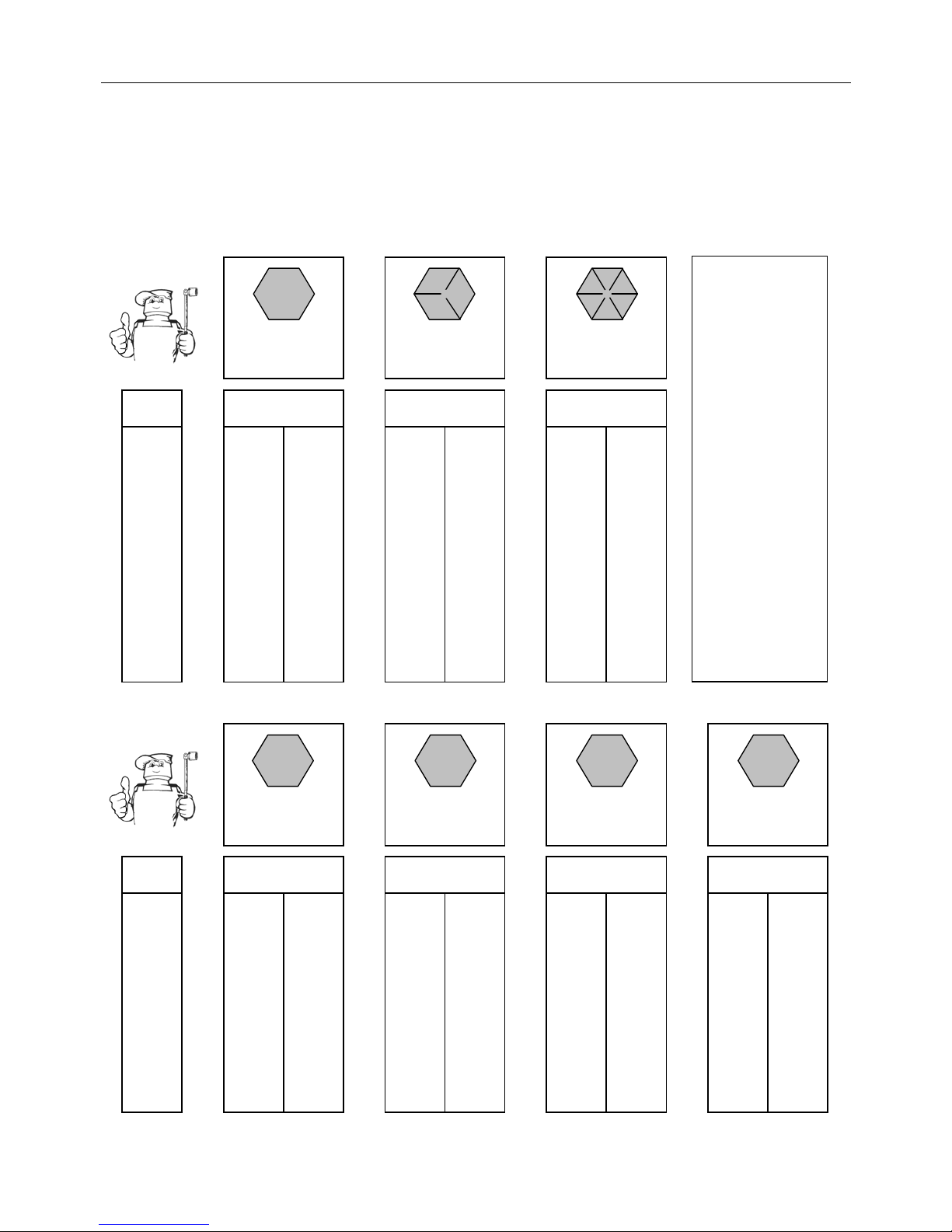
The chart below lists the correct tightening torque for fasteners. This chart should be
referred to when tightening or replacing bolts in order to determine the grade of bolt and
the correct torque unless specific torque values are assigned in the text of the manual.
Recommended torque is quoted in Foot-Pounds and Newton-Metres within this manual.
The equation for conversion is 1 Nm. = 1.356 ft. lbs.
TORQUE VALUES FOR IMPERIAL BOLTS
Bolt
Dia. ft.lb. Nm. ft.lb. Nm. ft.lb. Nm.
1/4" 5.
57.5
9
12.
2
12.
5
17.0
5/16" 11 15.0 18 25.0 2
6
35.
2
3/8" 20 27.0 33 45.0 4
6
63.0
7/16" 3
2
43.0 5
2
70.0 7
5
100.0
1/2" 50 68.0 80 110.0 11
5
155.0
9/16" 70 95.0 115 155.0 160 220.0
5/8" 100 135.0 160 220.0 22
5
305.0
3/4" 17
5
240.0 280 380.0 400 540.0
7/8" 17
5
240.0 450 610.0 650 880.0
1" 270 360.0 675 915.0 97
5
1325.0
1-1/8" 37
5
510.0 850 115.0 1350 1830.0
1-1/4" 530 720.0 1200 1626.0 1950 2650.0
1-3/8" 700 950.0 1550 2100.0 2550 3460.0
1-1/2" 930 1250.0 2100 2850.0 3350 4550.0
TORQUE VALUES FOR METRIC BOLTS.
Bolt
Dia. ft.lb. Nm. ft.lb. Nm. ft.lb. Nm. ft.lb. Nm.
6mm 4.
5
6.1 8.
5
11.5 1
2
16.3 14.5 20.0
8mm 11 14.
9
20 27.1 30 40.1 35 47.
5
10mm 21 28.5 40 54.
2
60 81.4 70 95.0
12mm 37 50.
2
70 95.0 10
5
140.0 120 160.0
14mm 60 81.4 110 150.0 16
5
225.0 190 260.0
16mm 9
2
125.0 175 240.0 25
5
350.0 300 400.0
18mm 12
5
170.0 250 340.0 350 475.0 410 550.0
20mm 180 245.0 350 475.0 500 675.0 580 790.0
22mm 250 340.0 475 645.0 67
5
915.0 800 1090.0
24mm 310 420.0 600 810.0 850 1150.0 1000 1350.0
27mm 450 610.0 875 1180.0 1250 1700.0 1500 2000.0
30mm 62
5
850.0 1200 1626.0 1700 2300.0 2000 2700.0
Head Marking
12.
9
Value (Dry)Value (Dry) Valu e (Dry)
Head Marking Head Marking
8.8 10.
9
Head Marking
4.8
Value (Dry)
Value (Dry)Value (Dry)Value (Dry)
Head Marking Head Marking Head Marking
No Marks Three Line
s
Six Lines
Grade Tw o Grade Five Gra de E i ght
NOTE:
The values in
the chart apply
to fasteners as
received fro m
the supplier,
dry or when
lubricated with
normal engine
oil. They DO
NOT apply if
special
graphited,
molydisulphide
greases, or
other extreme
p
ressure
lubricants are
used. This
applies to both
UNF and UNC
coarse threads
.
Page 50

 Loading...