

Twose Opticut 220, Opticut 300, Opticut 260 Operator And Parts Manual

OPTICUT
DISC MOWERS
Models 220, 260 & 300
OPERATOR & PARTS MANUAL
Publication 655 Part No.22674.55
Twose of Tiverton Limited
6 Chinon Court,
Lower Moor Way,
Tiverton Business Park,
Tiverton,
Devon. EX16 6SS.
Telephone: (01884) 253691
Fax: (01884) 255189
Email sales@twose.com
Web: www.twose.com


IMPORTANT
VERIFICATION OF WARRANTY REGISTRATION
DEALER WARRANTY INFORMATION & REGISTRATION VERIFICATION
It is imperative that the selling dealer registers this machine with Twose of Tiverton Limited
before delivery to the end user – failure to do so may affect the validity of the machine
warranty.
To register machines go to the Twose web site at www.twose.com, log onto ‘Dealer
Inside’ and select the ‘Machine Registration button’ which can be found in the Service
Section of the site. Confirm to the customer that the machine has been registered in the
section below.
Should you experience any problems registering a machine in this manner please contact
the Twose Office on 01884 253691.
Registration Verification
Dealer Name: ……………………..…………………………………………………………….
Dealer Address: …….………………………………………………………………………….
Customer Name: ……………………..…………………………………………………………
Date of Warranty Registration: ……/……/...…… Dealer Signature: ………………..……
NOTE TO CUSTOMER / OWNER
Please ensure that the above section above has been completed and signed by the selling
dealer to verify that your machine has been registered with Twose of Tiverton Limited.
IMPORTANT: During the initial ‘bedding in’ period of a new machine it is the customer’s responsibility
to regularly inspect all nuts, bolts and hose connections for tightness and re-tighten if required. New
hydraulic connections occasionally weep small amounts of oil as the seals and joints settle in – where
this occurs it can be cured by re-tightening the connection – refer to torque settings chart below. The
tasks stated above should be performed on an hourly basis during the first day of work and at least
daily thereafter as part of the machines general maintenance procedure.
TORQUE SETTINGS FOR HYDRAULIC FITTINGS
HYDRAULIC HOSE ENDS PORT ADAPTORS WITH BONDED SEALS
BSP Setting Metric BSP Setting Metric
1/4” 18 Nm 19 mm 1/4” 34 Nm 19 mm
3/8” 31 Nm 22 mm 3/8” 47 Nm 22 mm
1/2” 49 Nm 27 mm 1/2” 102 Nm 27 mm
5/8” 60 Nm 30 mm 5/8” 122 Nm 30 mm
3/4” 80 Nm 32 mm 3/4” 149 Nm 32 mm
1” 125 Nm 41 mm 1” 203 Nm 41 mm
1.1/4” 190 Nm 50 mm 1.1/4” 305 Nm 50 mm
1.1/2” 250 Nm 55 mm 1.1/2” 305 Nm 55 mm
2” 420 Nm 70 mm 2” 400 Nm 70 mm

WARRANTY POLICY
WARRANTY REGISTRATION
All machines must be registered, by the selling dealer with Twose of Tiverton Ltd, before delivery
to the end user. On receipt of the goods it is the buyer’s responsibility to check that the Verification
of Warranty Registration in the Operator’s Manual has been completed by the selling dealer.
1. LIMITED WARRANTIES
1.01. All machines supplied by Twose of Tiverton Ltd are warranted to be free from defects in
material and workmanship from the date of sale to the original purchaser for a period of 12
months, unless a different period is specified.
1.02. All spare parts supplied by Twose of Tiverton Ltd and purchased by the end user are
warranted to be free from defects in material and workmanship from the date of sale to the
original purchaser for a period of 6 months. All parts warranty claims must be supported by a
copy of the failed part invoice to the end user. We cannot consider claims for which sales
invoices are not available.
1.03. The warranty offered by Twose of Tiverton Ltd is limited to the making good by repair or
replacement for the purchaser any part or parts found, upon examination at its factory, to be
defective under normal use and service due to defects in material or workmanship. Returned
parts must be complete and unexamined. Pack the component(s) carefully so that any transit
damage is avoided. All ports on hydraulic items should be drained of oil and securely plugged
to prevent seepage and foreign body ingress. Certain other components, electrical items for
example, may require particular care when packing to avoid damage in transit.
1.04. This warranty does not extend to any product from which Twose of Tiverton Ltd’s serial
number plate has been removed or altered.
1.05. This warranty does not apply to any part of the goods, which has been subjected to improper
or abnormal use, negligence, alteration, modification, fitment of non-genuine parts, accident
damage, or damage resulting from contact with overhead power lines, damage caused by
foreign objects (e.g. stones, iron, material other than vegetation), failure due to lack of
maintenance, use of incorrect oil or lubricants, contamination of the oil, or which has served
its normal life. This warranty does not apply to any expendable items such as blades, belts,
clutch linings, filter elements, flails, flap kits, skids, soil engaging parts, shields, guards, wear
pads, pneumatic tyres or tracks.
1.06. Temporary repairs and consequential loss - i.e. oil, downtime and associated parts are
specifically excluded from the warranty.
1.07. Warranty on hoses is limited to 12 months and does not include hoses which have suffered
external damage. Only complete hoses may be returned under warranty, any which have
been cut or repaired will be rejected.
1.08. Machines must be repaired immediately a problem arises. Continued use of the machine
after a problem has occurred can result in further component failures, for which Twose of
Tiverton Ltd cannot be held liable, and may have safety implications.
1.09. If in exceptional circumstances a non Twose of Tiverton Ltd part is used to effect a repair,
warranty reimbursement will be at no more than Twose of Tiverton Ltd‘s standard dealer cost
for the genuine part.
1.10. Except as provided herein, no employee, agent, dealer or other person is authorised to give
any warranties of any nature on behalf of Twose of Tiverton Ltd.
1.11. For machine warranty periods in excess of 12 months the following additional exclusions
shall apply:
1.11.1. Hoses, exposed pipes and hydraulic tank breathers.
1.11.2. Filters.
1.11.3. Rubber mountings.
1.11.4. External electric wiring.
1.11.5. Bearings and seals.

1.12. All service work, particularly filter changes, must be carried out in accordance with the
manufacturer’s service schedule. Failure to comply will invalidate the warranty. In the event of
a claim, proof of the service work being carried out may be required.
1.13. Repeat or additional repairs resulting from incorrect diagnosis or poor quality previous repair
work are excluded from warranty.
NB Warranty cover will be invalid if any non-genuine parts have been fitted or used. Use of nongenuine parts may seriously affect the machine’s performance and safety. Twose of Tiverton Ltd
cannot be held responsible for any failures or safety implications that arise due to the use of nongenuine parts.
2. REMEDIES AND PROCEDURES
2.01. The warranty is not effective unless the Selling Dealer registers the machine, via the Twose
of Tiverton Ltd web site and confirms the registration to the purchaser by completing the
confirmation form in the operator’s manual.
2.02. Any fault must be reported to an authorised Twose of Tiverton Ltd dealer as soon as it
occurs. Continued use of a machine, after a fault has occurred, can result in further
component failure for which Twose of Tiverton Ltd cannot be held liable.
2.03. Repairs should be undertaken within two days of the failure. Claims submitted for repairs
undertaken more than 2 weeks after a failure has occurred, or 2 days after the parts were
supplied will be rejected, unless the delay has been authorised by Twose of Tiverton Ltd.
Please note that failure by the customer to release the machine for repair will not be
accepted as a reason for delay in repair or submitting warranty claims.
2.04. All claims must be submitted, by an authorised Twose of Tiverton Ltd Service Dealer, within
30 days of the date of repair.
2.05. Following examination of the claim and parts, Twose of Tiverton Ltd will pay, at their
discretion, for any valid claim the invoiced cost of any parts supplied by Twose of Tiverton Ltd
and appropriate labour and mileage allowances if applicable.
2.06. The submission of a claim is not a guarantee of payment.
2.07. Any decision reached by Twose of Tiverton Ltd is final.
3. LIMITATION OF LIABILITY
3.01. Twose of Tiverton Ltd disclaims any express (except as set forth herein) and implied
warranties with respect to the goods including, but not limited to, merchantability and fitness
for a particular purpose.
3.02. Twose of Tiverton Ltd makes no warranty as to the design, capability, capacity or suitability
for use of the goods.
3.03. Except as provided herein, Twose of Tiverton Ltd shall have no liability or responsibility to the
purchaser or any other person or entity with respect to any liability, loss, or damage caused
or alleged to be caused directly or indirectly by the goods including, but not limited to, any
indirect, special, consequential, or incidental damages resulting from the use or operation of
the goods or any breach of this warranty. Notwithstanding the above limitations and
warranties, the manufacturer’s liability hereunder for damages incurred by the purchaser or
others shall not exceed the price of the goods.
3.04. No action arising out of any claimed breach of this warranty or transactions under this
warranty may be brought more than one (1) year after the cause of the action has occurred.
4. MISCELLANEOUS
4.01. Twose of Tiverton Ltd may waive compliance with any of the terms of this limited warranty,
but no waiver of any terms shall be deemed to be a waiver of any other term.
4.02. If any provision of this limited warranty shall violate any applicable law and is held to be
unenforceable, then the invalidity of such provision shall not invalidate any other provisions
herein.
4.03. Applicable law may provide rights and benefits to the purchaser in addition to those provided
herein.


EC DECLARATION OF CONFORMITY
Conforming to EEC Directive 89/392/EEC
We,
TWOSE OF TIVERTON LIMITED,
6 Chinon Court, Lower Moor Way,
Tiverton Business Park, Tiverton, Devon, EX16 6SS.
Declare under our sole responsibility that:
The product (type) ………………………………………………………………………
…………………………………………………………………………………………...
Product Code ……………………………………………………………………………
Serial No. & Date ……………………………………. Type …………………………..
Manufactured by the above company/* …………………………………………………
…………………………………………………………………………………………...
(* insert business name and full address if not stated above)
Complies with the required provisions of the Machinery Directive 98/37/EC, *
previously Directive 89/392/EEC as amended by Directives 91/368/EEC, 93/44/EEC
and 93/68/EEC.
For the relevant implementation of the safety and health requirements mentioned in the
Directives, the following standards have been respected:
EN 292-1/1991 EN292-2/1991 EN294/1992 EN349/1993
EN 1553/1999 EN 1152/1994 EN 953/1997 EN 982/1996
Signed …………………………..…………………………………………………….....
on behalf of TWOSE OF TIVERTON Responsible Person
Status: Chief Design Engineer Date: August 2010
Rotary Disc Mower
O
p
ticut 220 / 260 / 300


LIST OF CONTENTS
Page No.
Technical Data 1
Machine Description 2
Safety Information 3
Safety Decals 5
Tractor Requirements 6
Attachment to Tractor 7
Setting of Side Position 7
Vertical Adjustment 8
Frame Height 9
PTO Shaft 10
Hydraulic Connection 11
Post Attachment Checks 12
Spring Assisted Weight Distribution 13
Moving into Transport Position 14
Moving into Work Position 15
Mowing Instructions 16
Breakback Protection System 18
Machine Removal 18
General Maintenance 19
Storage 29


OPTICUT 220/260/300
Rotary Disc Mowers
1
TECHNICAL DATA
SPECIFICATION OPTICUT 220 OPTICUT 260 OPTICUT 300
Attachment (3-point hitch)
Cat. II Cat. II Cat. II
Working width
2119mm 2472mm 2895mm
Weight
520kg 560kg 590kg
Transport height
2745mm 3100mm 3530mm
Transport width
1935mm 1935mm 1935mm
Maximum PTO speed
540RPM 540RPM 540RPM
Disc rotation speed
3000RPM 3000RPM 3000RPM
No. of discs
5 6 7
No. of blades
10 12 14
Minimum power requirement
30Kw/40HP 38Kw/50HP 48Kw/60HP
Cutting capacity
2.6 ha/h 3 ha/h 3.5 ha/h
Working speed
Up to 18 km/h Up to 18 km/h Up to 18 km/h
MACHINE SERIAL NUMBER PLATE
All machines will have a serial number plate fitted to them stating; the machine model, serial
number of the machine, and the machine’s weight. When ordering replacement parts or
requesting service information always quote the machine model and serial number as
stated on its serial number plate.

OPTICUT 220/260/300
Rotary Disc Mowers
2
DESCRIPTION
The Twose Opticut Series disc mowers are three-point linkage tractor mounted agricultural
implements specifically designed for the mowing of grass and clover on even terrain. The
machines feature belt driven cutterbars fitted with rotating discs each equipped with 2
cutting knives that perform efficient cutting of vegetation.
Mower components are protected by a mechanical breakback system and the machines are
equipped with a hydraulic ‘fold up’ system for ease of transportation.
These machines must only be used to perform the designated task for which they were
designed. Use of these machines for any other function may cause damage to the machine
and possible injury to the operator or other persons.

OPTICUT 220/260/300
Rotary Disc Mowers
3
SAFETY INFORMATION
In the interest of safety it is important that great care is adopted at all times during the attachment,
transportation, operation and maintenance of this machine. Both the owner and the operator of the
machine should read and understand the following section to ensure the safety of themselves and all
other persons who enter into the close proximity of these machines.
In addition to the instructions stated here always abide by general safety and accident
regulations.
Safety and warning decals placed on the machine give important instructions for safe
work - take them into consideration for your safety and the safety of others.
While driving on public roads always abide by traffic signs and road regulations.
Familiarise yourself with the controls and functions of the machine and practice them in
a safe location before attempting to start work.
Never approach this machine whilst it is working or running – switch off the machine
and wait until it has stopped fully before approaching.
Do not wear loose fitting clothes in the vicinity of this machine - clothes should fit tight
to the user's body.
Check no one is near to, or on, the machine before attempting to start or transport it.
Ensure your visibility is kept clear at all times.
Never permit anyone to ride on this machine.
Implements should always be attached according to the manufacturer’s instructions
and fastened correctly to the prescribed devices using the correct components.
When disconnecting the machine from the tractor select a firm level site and use the
support leg.
Take care when connecting or disconnecting the implement to the tractor – keep
onlookers at a safe distance.
Ensure controls for the machine are positioned such that the machine cannot
accidentally be started during transport.
For transportation on the road, prepare and secure the machine according to the
manufacturer's instructions.
Never leave the driver seat whilst the tractor or the machine is running.

OPTICUT 220/260/300
Rotary Disc Mowers
4
Always adjust the driving speed to suit the driving conditions. Avoid fast turning
when driving uphill, downhill or across a slope. Braking performance and turning ability
will be affected when implements are connected or mounted to the tractor - allow
extra time for turning and braking.
Never attempt to operate a machine without its safety devices fitted or incorrectly
secured.
Ensure all bystanders are kept at a safe distance from a moving or working machine.
Even when the machine is unattached some hydraulic or mechanical components on
the machine are able to be rotated or moved by hand and are therefore capable of
causing injury to fingers or hands due to trapping. Wherever possible secure these
components during storage to prevent accidental injuries.
Always place the machine in a safe position before leaving the tractor - lower the
implement completely, switch off the engine and remove the ignition key.
Never permit anyone between the machine and the tractor whilst either is working or
when the machine is in a raised position.
Only use machines on a tractor that is capable of taking its weight - use weights or
ballast as required ensuring stability of the unit.
Be aware at all times of the width, height and length of any machinery you are
operating – especially when transporting on the public highway or near obstructions.
Ensure the work area is clear of obstructions before starting work – clear stones, wire,
glass or any other dangerous objects from the work site before attempting to start work.
Although the information given here covers a wide range of safety subjects it is impossible to predict
every eventuality that can occur under differing circumstances whilst operating this machine. No
advice given here can replace ‘good common sense’ and ‘total awareness’ at all times but will go a
long way towards the safe use of your Twose machine.
OPTICUT 220/260/300
Rotary Disc Mowers
5
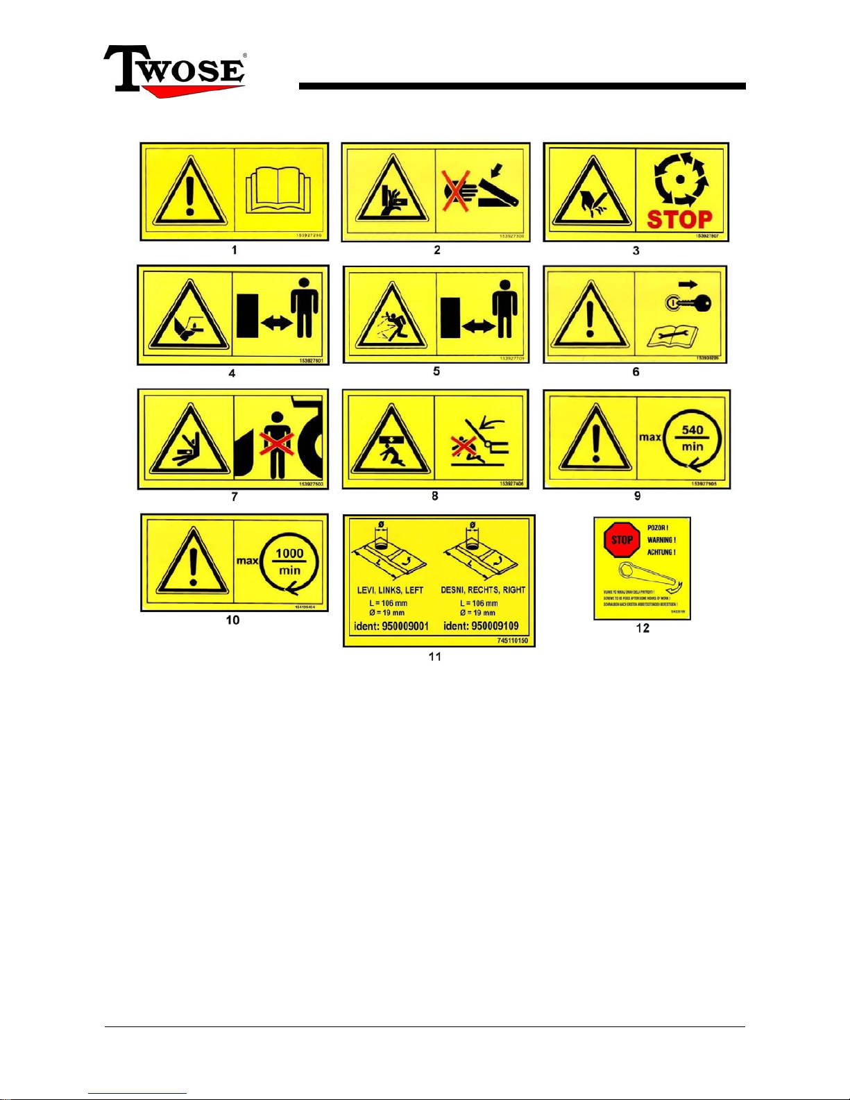
SAFETY DECALS
1. WARNING! Always ‘Read the Operator Manual’.
2. DANGER! Pinch & Crush Zone – Keep hands and limbs clear whilst machine is
working.
3. DANGER! Wait until machine has stopped completely before approaching.
4. DANGER! Keep clear of mower knife area whilst tractor or machine is running.
5. DANGER! Keep clear of machine whilst tractor or machine is running.
6. WARNING! Switch off tractor engine & remove key before performing
maintenance or repair.
7. DANGER! Keep clear of danger area between tractor and machine.
8. DANGER! Keep clear of raised machine.
9. WARNING! Maximum RPM – 540RPM machines only (where applicable).
10. WARNING! Maximum RPM – 1000RPM machines only (where applicable).
11. INFORMATION! Blade Information
12. INFORMATION! Check tightness of nuts & bolts every couple of working hours.

OPTICUT 220/260/300
Rotary Disc Mowers
6
TRACTOR REQUIREMENTS
The tractor to which this machine is to be fitted must meet the following criteria:
o 3-point linkage connection – Cat. II.
o Minimum power requirement of: 38kW (50HP) for Opticut 260 machines
48kW (60HP) for Opticut 300 machines
o PTO shaft speed: Maximum 540RPM
o Hydraulic service connection.
OPTICUT 220/260/300
Rotary Disc Mowers
7
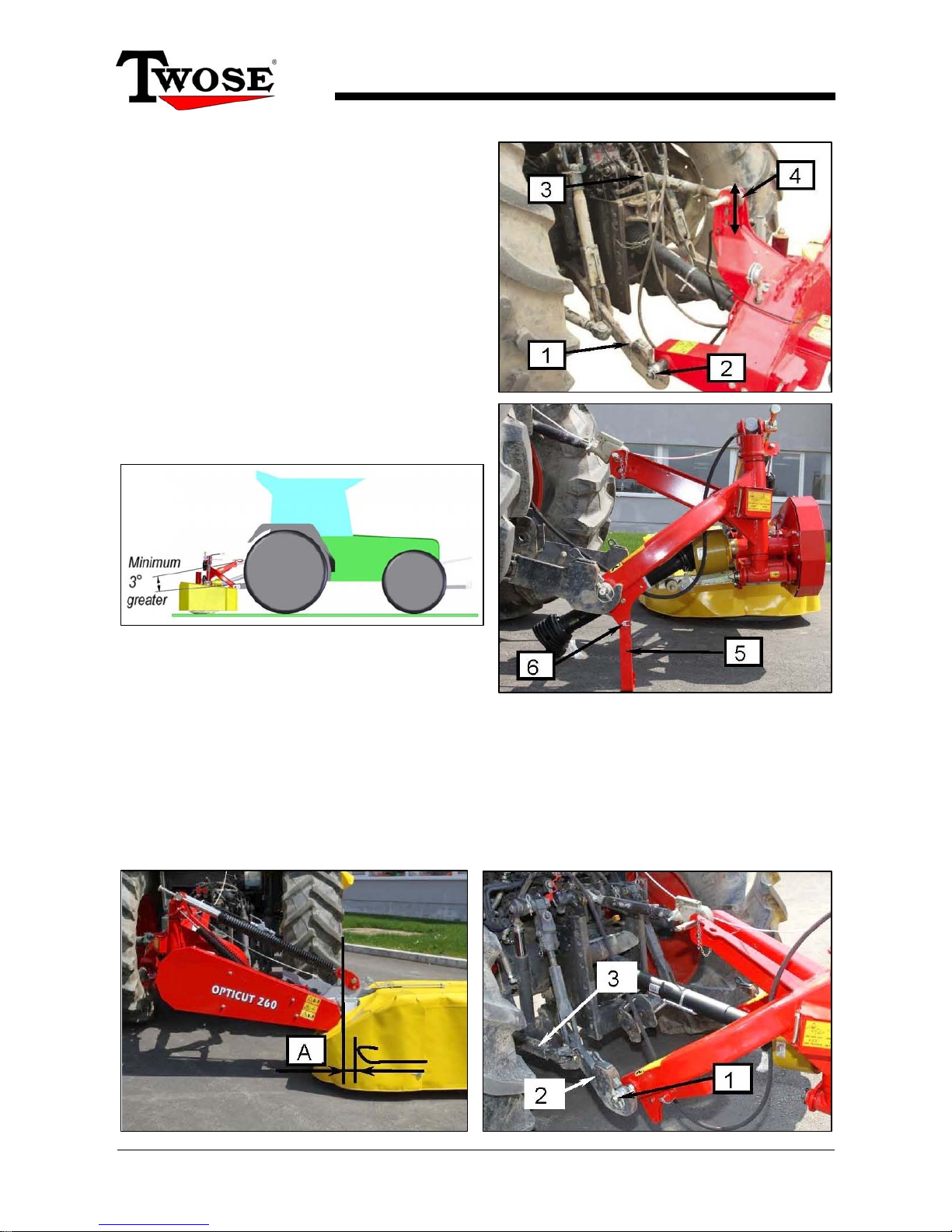
Attachment to Tractor
Select a firm level site on which to attach the
mower to the tractor.
Reverse tractor up to machine positioning
linkage arms (1) at a suitable height for
attachment, secure in position with locking pins
(2).
Fit top link (3) and secure with link pin and
locking pin (4).
Ensure linkage lift rods on both sides are set at
the same height and secured.
Note: The top link should be adjusted to an angle of
at least 3° greater than the lower links arms – refer
to diagram below.
Raise support leg (5) into the stowed position
and secure in place with its lock pin (6). Do not
remove the support leg.
Setting of Side Position
The working position of the machine (side position) is set by sideways adjustment of the
lower link arms to a point where the cutting area of the machines is just beyond the tractor
wheel on its working side – see illustrations below.
Shift the mower sideways on the lower link arms (2) to achieve the required distance (A),
secure in position with stabiliser arms (3). Additional shift (±
100mm) is available by altering
the position of the lower linkage pins.
OPTICUT 220/260/300
Rotary Disc Mowers
8
Vertical Adjustment (Side to Side)
Ensure the frame of the machine is
vertical as shown opposite ►
◄ If required, adjust the lower links (1) and lift rods
(2) to bring the frame into the vertical (side to side)
position.
Vertical Adjustment (Front to Back)
The correct vertical position of the frame, front to back, is with the frame tilted forward by 2°
in the direction of travel, this can be gauged by viewing the protection curtain (1); all the
lower edges should be equidistant to the ground when the machine is set correctly.
Rotate the adjuster nut (3) on top link (2) to achieve this setting – refer to illustrations below.
Note: This 2° inclination of the machine will produce a grass cut height of 50 – 55mm. The
tilt angle may be adjusted to suit individual preference but under no circumstances should it
exceed 7°.
The support leg is designed so the machine is automatically leaned forward by 2° when the
machine is disconnected.

OPTICUT 220/260/300
Rotary Disc Mowers
9
Adjusting Frame Work Height
Place the machine into the working position; the optimal working position is when the base
end of the support arm (1) is located midway within its guide slot – an indicator ‘notch’ (2)
marks this position. Raise or lower the machine on the tractors three-point linkage to
achieve this central position. Secure the linkage in position when the working height has
been set.
Note: This machine has the ability to work with the cutterbar at angles of between -30° and
+45°; when working at these angles the cutterbar should be brought back into the parallel
position every 15 minutes or so and run for 4 minutes to ensure continuous lubrication.
PTO Shaft Fitment
On initial fitment the PTO shaft halves (1 & 2) will need to be measured and cut to suit the
particular application – refer to following page for details.
Install PTO shaft (3) and fit torque chains to PTO guard (4) at each end of the shaft to
prevent them from rotating with the shaft.
Check the PTO shaft does not foul on the tractor or machine during normal operation and
manoeuvring; failure to observe this can result in damage to components.
OPTICUT 220/260/300
Rotary Disc Mowers
10
PTO Driveshaft
The PTO driveshaft attaches between the tractor and the machine gearbox to transfer the
power required to the run and operate the machine – it is important to achieve the correct
shaft length to avoid risk of it ‘bottoming out’ when raising or lowering the machine.
The procedure for measuring and cutting the shaft is as follows:
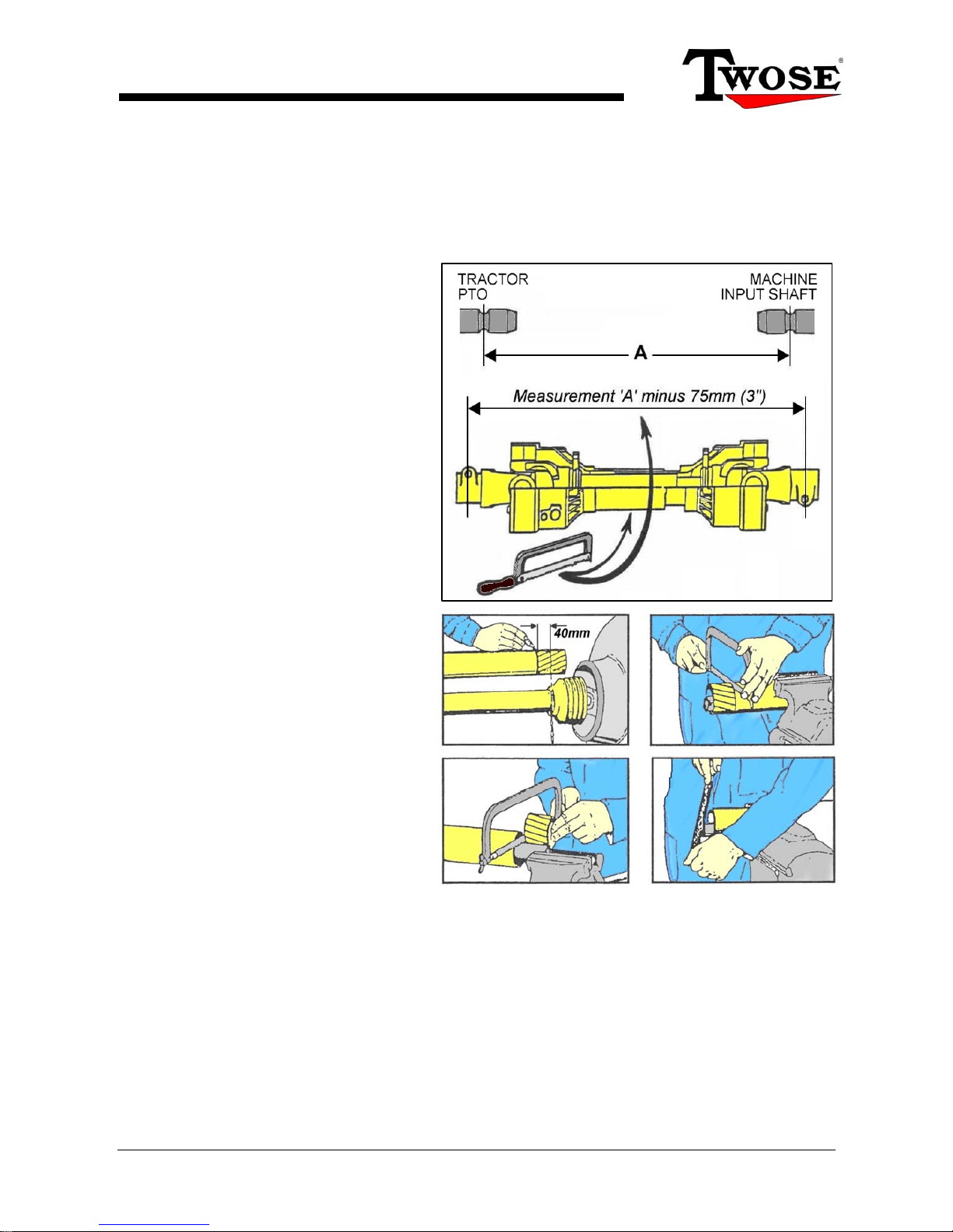
Measuring the PTO Shaft
With the machine attached to the
tractor in the working position measure
the horizontal distance ‘A’ from the
tractor’s PTO to the input shaft on the
machines gearbox and subtract 75mm
(3”) – this figure is the required shaft
length.
Place the fully closed PTO shaft on the
ground and measure its overall length,
if the shaft is shorter than the required
length you can use it without the need
to shorten - providing it allows for a
minimum 150mm (6”) overlap when
fitted.
If the shaft is longer subtract the
required shaft length plus an additional
75mm (3”) - the resulting figure is the
excess length that will need to be
removed from each half of the shaft.
Cutting the PTO Shaft
Separate the two halves and using the
measurement obtained above shorten
both the plastic guarding and the inner
steel profile tubes of each shaft by this
same amount. De-burr the cut tubes
with a file to remove rough or sharp
edges and thoroughly clean to remove
swarf before greasing, assembling and
fitting the shaft.
Always secure the PTO guards with torque chains to prevent them from rotating with the
shaft. Check to ensure the shaft does not contact or foul tractor or machine components
during normal operation - failure to observe this can result in damage to the tractor and/or
machine.
NOTE: For subsequent use with different tractors the shaft should be measured again to
check suitability – there must be a minimum shaft overlap of 150mm (6”).
Maintenance
To increase the working life of the PTO shaft it should be periodically checked, cleaned and
lubricated – refer to the PTO maintenance section for further details on this subject.
OPTICUT 220/260/300
Rotary Disc Mowers
11
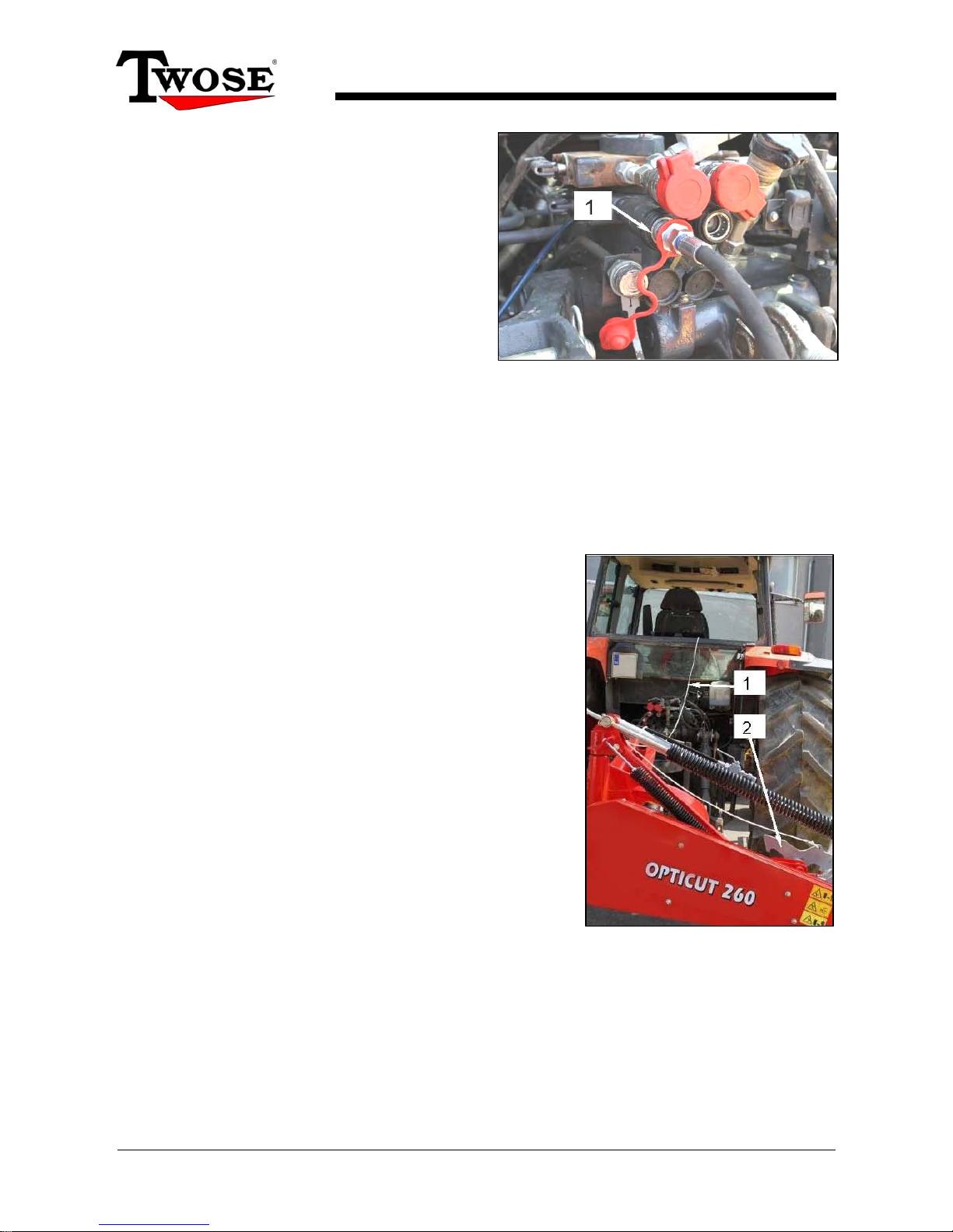
Hydraulic Connection
The machine requires one hydraulic
connection; this is for operation of the
hydraulic ram that raises and lowers the
cutterbar.
The minimum working pressure necessary to
operate the machine is 50bar and a maximum
of 200bar.
Before connecting the hydraulic hose (1) to the tractor ensure that the control for that
service is in the midpoint ‘off’ position and the system is not pressurised.
NOTE: Ensure all hydraulic connections are kept free from dirt and other contaminates that
can cause damage to a hydraulic system.
Transport Locking Mechanism
Route the operation cord (1) for the transport locking
mechanism (2) into the tractor cab through the rear
window – ensure sufficient slack is retained in the cord
run to avoid accidental operation of the mechanism.
Fix the cord to a suitable location in the cab that is easily
accessible to the operator.
WARNING!
The transport latch operation cord must be slack at all
times to avoid unintentional operation of the latch. Ensure
the cord is kept clear of any components on the tractor
and the machine that may cause accidental tightening of
the cord and operation of the latch.
Ballast
Add front end weights to the tractor if required to increase stability of the unit for both
transportation and work. Refer to tractor manufacturer’s handbook for advice on ballasting.

OPTICUT 220/260/300
Rotary Disc Mowers
12
Post Attachment Checks
After attaching the machine the following checks should be performed, ensure the tractor is
switched off and the starting key removed.
Check the attachment of the machine to the tractor;
Operating height of the hitch.
Hitch installation.
Frame angle (2° inclination in the direction of travel).
Check position of the support leg.
Check all guarding is correctly located and undamaged.
Check lubrication levels in all drives.
Check all vital parts are present and working correctly.
Check parts for wear, damage or looseness on used machines, particularly;
Blades.
Discs.
Quick change blades.
Belts.
Guards.
Protection curtain.
In the event of damage or excessive wear to vital parts of the machine, replacements
must be sourced and fitted before attempting to operate it. Each disc on the machine is
fitted with 2 blades; these must be new or evenly worn. For safety and long working life
always replace components with genuine parts from the manufacturer.
With all persons are kept at a safe distance from the machine, conduct a test run with the
machine running at 540RPM.
In the event of excessive noise and/or vibration, stop the machine and correct the
problem.
If the problem continues, contact authorised service centre for advice or help.
If all the above criteria are met the machine is ready for operation.
OPTICUT 220/260/300
Rotary Disc Mowers
13
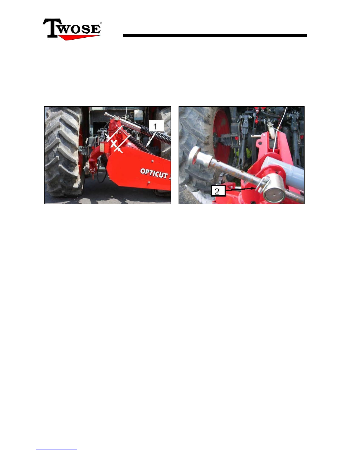
Spring Assisted Weight Distribution
To aid weight distribution and reduce mechanical stress the machine is fitted with 2 spring
dampeners; the smaller spring supports the heel of the cutterbar and the larger spring
supports the whole cutterbar. These are adjustable to suit operating preference and specific
working conditions.
Factory setting for the spring is: Distance ‘X’ = 70mm
Spring Adjustments
To reduce spring tension on the cutterbar, reduce distance ‘X’ on small spring (1) and
relocate pin (2) on the large spring to the previous hole position, to increase tension,
increase distance ‘X’ and move pin (2) to the next hole.
NOTE: Adjustment to the larger spring must be performed with the machine folded into the
transport position.
OPTICUT 220/260/300
Rotary Disc Mowers
14
▲
Ensure ram tap is closed for transportation.
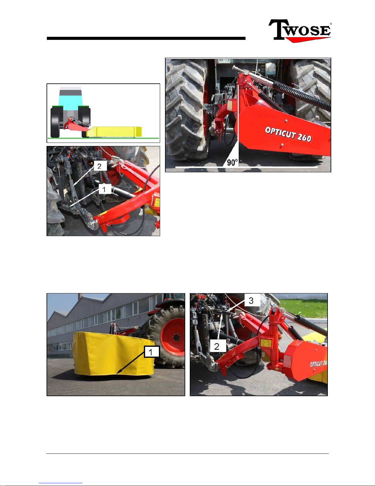
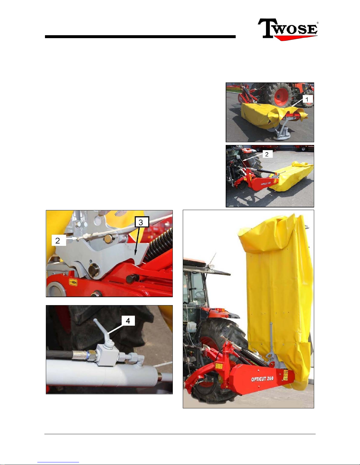
Moving Into Transport Position
For transportation of the machine the cutterbar must be raised into the vertical position; the
procedure for moving into transport is as follows:
With the machine in the horizontal work position, fold the
outer end of the protection curtain (1) over the top of the
cutterbar.
Pull and retain tension on the operation cord (2) to
disengage the transport locking mechanism.
Operate the hydraulic ram to raise the cutterbar.
Tension on the operation cord can be released once the
cutterbar has reached an angle in excess of 60°.
Continue operation of the ram until the cutterbar is
upright at 90° and the transport lock has fully engaged.
Close tap (4) on the ram valve.
The machine is now folded and ready for transportation.
WARNING! Always be aware of the height of the machine during transport and take extra care when
manoeuvring close to buildings and under low bridges.
OPTICUT 220/260/300
Rotary Disc Mowers
15
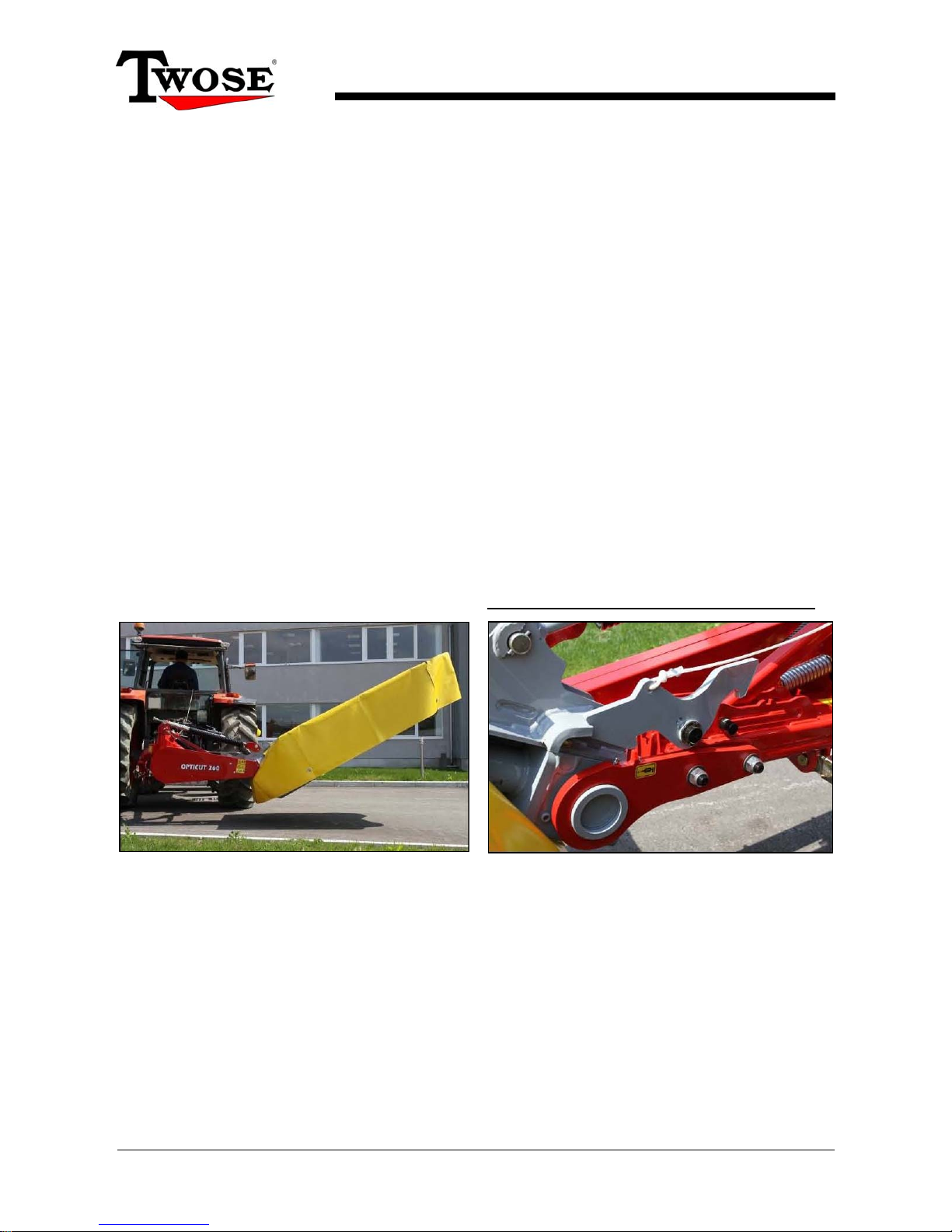
Moving from Transport into Work Position
The procedure for moving from transport to work position is basically a reversal of moving
from work into transport.
Open tap on ram valve.
Pull and retain tension on the operation cord to disengage the transport locking
mechanism.
Operate the hydraulic ram to lower the cutterbar.
Tension on the operation cord can be released once the cutterbar reaches an angle of
approximately 80°.
Continue operation of the ram until the cutter has reached its horizontal work position
and the latch has re-engaged.
Re-position the protection curtain.
The machine is now ready for work.
Raising and Lowering the Cutterbar in Work
Raising and lowering the cutterbar when moving between rows or turning on the headland
is performed by operation of the hydraulic ram. Do not pull the cord for the transport latch.
Raising the cutterbar during work is by operating the ram with the transport latch engaged.
CAUTION!
When raising the cutterbar with the machine running there is risk of danger from flying
objects such as stones or other hard objects; ensure persons and animals are clear of the
danger zone before raising the cutterbar when the machine is running. Always cease
working and stop the machine when persons approach, do not re-start until they are clear of
the danger zone.

OPTICUT 220/260/300
Rotary Disc Mowers
16
Instructions for Safe Mowing
Always ensure that each disc is fitted with 2 knives, either new or equally worn.
Always replace damaged or worn blades, knives, and knife holders immediately – never
attempt to operate the machine with any of these components in a damaged or overly
worn condition.
Stop the machine immediately if an increase in noise or vibration is experienced –
continue work only when the reason for the disturbance has been investigated and
resolved. Ensure both the machine and the tractor’s engines are switched off before
nearing the mower to investigate.
Only operate the machine at the correct PTO speed.
Mowing Instructions
Allow the mower to reach its maximum permitted PTO speed before entering it into the
grass to cut and keep the machine at this speed for the duration of the mowing to
ensure a clean cut.
Select a gear that will enable best mowing according to the ground conditions.
Replace worn knives – sharp knives produce a cleaner more efficient cut.
 Loading...