

Page 1

Two-Rock
Bloomfield
Drive
100, 50, 40
OWNERS MANUAL
Page 2

Dear Customer,
Thank you for your purchase of a
Two-Rock
amplifier.
As a discerning guitarist, you know the road to great tone begins with
great components. Our classic design of carefully selected parts and
hand-built approach combine to make an extremely versatile instrument.
Please take the time to read this manual. We hope it will answer any
questions that you may have.
We extend a warm welcome to you as a member of a select group of
musicians who have chosen a Two-Rock amplifier.
Important Safety Instructions
1. Read these instructions
2. Keep these instructions
3. Heed all warnings
4. Follow all instructions
5. Do not use this apparatus near water
6. Clean only with dry cloth
7. Do not block any ventilation openings. Install in accordance with the manufacturer’s instructions
8. Do not install near any heat sources such as radiators, heat registers, plugs, and the point
where they exit from the apparatus
9. Protect the power cord from being walked on or pinched particularly at plugs and the point
where they exit from the apparatus
10. Only use attachments/accessories specified by the manufacturer
11. Unplug this apparatus during lightning storms or when unused for long periods of time
12. Refer all servicing to qualified service personnel. Servicing is required when the apparatus has
been damaged in any way, such as power-supply cord or plug is damaged, liquid has been spilled
or objects have fallen into the apparatus, the apparatus has been exposed to rain or moisture,
does not operate normally, or has been dropped
13. CAUTION: To disconnect the unit completely from the MAINS, unplug the unit. Turning the
power switch off does not disconnect the unit completely from the MAINS.
Page 3
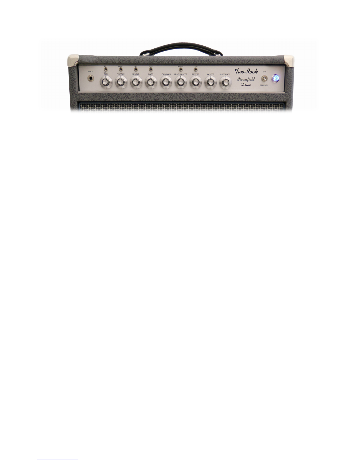
Front Panel Functions
1. INPUT JACK - Input to the amplifier. Plug in your instrument here.
2. GAIN - Adjusts the overall gain of the amplifier. Start with this control in the 12 o’clock
position. The amount of gain set here determines the amount of gain feeding the lead channel.
3. EQ1 / EQ2 - This switch allows you to choose between 2 completely different equalization
settings. EQ1 is a lower gain setting, with extended midrange and bass available when used in
conjunction with the middle and bass controls as well as the deep switch. This setting is
suitable for any style requiring a pure clean tone with a nice round bottom and plenty of
headroom. EQ2 is a higher gain setting. This setting is suitable for any style requiring a clean
to slightly distorted tone in clean mode, and more gain in the lead mode.
4. TREBLE- Adjusts the high frequency response. In the full counter-clockwise position, high
frequencies are bypassed. In the full clockwise position, high frequencies are allowed to pass
to the input gain stage.
5. BRIGHT - Boosts the high frequency response.
6. MIDDLE – Adjusts the mid-range response. In the full counter-clockwise position, the tone will
be somewhat “scooped” of mid-range response, emphasizing the highs and lows. In the full
clockwise position, mid-range frequencies are allowed to pass to the input gain stage.
7. MID - Boosts the mid-range frequency response.
8. BASS - Adjusts the bass response. In the full counter-clockwise position, low frequencies are
cut. In addition, the response of the treble and mid-range controls is greatly reduced. In the
full clockwise position, low frequencies are allowed to pass to the next gain stage.
9. DEEP - Boosts the low frequencies. This is a low frequency contour switch, changing the low
and low-mid response.
10. LEAD GAIN - Adjusts the input gain of the LEAD channel. The GAIN control cascades into this
control. This level can be set to match the input gain or can be set higher for more overdriven
levels.
11. LEAD MASTER - Adjusts the overall output level of the LEAD channel.
12. LEAD - This switch sends the instrument signal through the lead circuit, adding extra stages of
gain to the signal and enabling the lead gain and lead master controls. To enable foot switch
control of this function, switch must be in the down position.
13. BYPASS - This switch bypasses the TREBLE, MIDDLE, BASS tone controls. To enable
footswitch control of this function, switch must be in the down position. NOTE: Boost switches
will still be enabled.
Page 4

14. REVERB – This is a reverb return control. This is the amount of reverb signal returning from
the spring tank. At full counter-clockwise rotation, the reverb effect is defeated. Using the return
control (back panel) in conjunction with this reverb send control, a wide range of natural reverb
effects can be produced.
15. MASTER - Adjusts the overall output level of the amplifier. Both the clean and overdrive output
is controlled by this level. This level will also control how much signal is passed to any pedal
that is inserted into the effects loop.
16. PRESENCE - Adjusts the contour of high-frequency response. The high-frequency response
will increase as you advance the control clockwise.
17. STANDBY- Should be in the “STANDBY” position when you apply power to the unit. After a
few seconds, place the switch in the “ON” position to use the amplifier. You may leave the unit
“powered up” and place this switch in the “STANDBY” position to mute the output.
18. INDICATOR LAMP - This lamp will illuminate when the power switch is in the “up” position,
indicating the unit is receiving A/C power.
NOTE: All switches are ON in the “up” position
Page 5

Rear Panel Functions
1. A/C JACK - Connects the amplifier to A/C power via the power cord supplied. Unless
otherwise specified, your amplifier is designed to operate on 120 volts A/C, 60 cycles.
2. FUSE - See Fuse Chart
3. AC ON/OFF - Turns power on or off.
4. POWER HIGH/LOW –
100 Watt: In the 100 watt versions, this switch will change your amplifier output from 100 (HIGH)
to 50 (LOW) watts with no impedance mismatch.
50 Watt: In the 50 Watt versions, the HIGH power mode is fixed-bias and the LOW power is
cathode biased. While the Low setting may sound louder, you’ll notice a significant headroom
decrease.
40 Watt: In the 40 watt versions, this switch will change your amplifier output from 40 to 20 watts
with no impedance mismatch.
5. SPEAKER OUTPUT - There are three sets of speaker output jacks 4, 8, 16 ohms. Be sure to
match the impedance of your cabinet with the impedance (output) of the amplifier. We do not
recommend connecting more than one cab at a time. For multiple cabs, a splitter is the best
option. NEVER OPERATE YOUR AMPLIFIER WITHOUT A PROPER SPEAKER LOAD
CONNECTED.
6. EFFECTS LOOP - The effects loop is passive. Any effects inserted into loop will be run in
series after the preamp and before the power section. Most effects should have buffers on the
input and output section to correctly match the signal leaving and coming back. The Master
volume controls how much signal is sent to the send.
SEND - Use this jack to send the amplifiers signal to outboard effects
RETURN - Use this jack to connect the output of your effects to the amplifier
Page 6

7. REVERB SEND - The reverb send control determines the amount of signal applied to the
reverb tank. Low settings will create short decay times. Advancing the control clockwise increases
the signal applied to the tank for longer decay times. Use this control in conjunction with the
REVERB (front panel) control.
8. S/N- Your serial number is located here. We strongly suggest that you record this number and
have it handy in case you need service, or in the event that your amp is lost, stolen, or damaged.
9. FOOT SWITCH- The footswitch connects here with the included stereo TRS cable. The LEAD
and BYPASS functions can be activated via the footswitch. Front panel switches must be in the
down position for the foot switch to function.
FUSE CHART
Fuse Chart: All Fuses are 3AG Type 250 Volt SLO-BLO
100V 120V 220/230/240
40 and 50 Watt: 2.5amp 2.5amp 1.6amp
100 Watt: 3.2amp 3.2amp 2.5amp
FOOTSWITCH
LEAD (BLUE) - Switches amp into overdrive mode
BYPASS (RED) - Switches amp into a tone stack bypass mode
Page 7

TUBE COMPLIMENT
V1- 12AX7, Clean
V2- 12AT7, Reverb Drive
V3- 12AX7, Mixing Stage
V4- 12AX7, Lead
V5- 12AX7, Phase Inverter
V6, V7- 100/50 6L6WGC-STR, 40 Watt 6V6 Output
V8, V9- 100 6L6WGC-STR, 40 Watt 6V6 Output
Each fine production tube is tested and matched to our exacting specifications. External bias
adjustment and test points are located on the chassis near the output tube sockets. A digital
voltmeter and small screwdriver are required for bias adjustment.
BIAS ADJUSTMENTS:
Power up unit and connect proper speaker load.
Set master volumes and effects return controls to zero.
DO NOT apply any signal to the input during the biasing procedure!
Take unit off standby and allow a few seconds for the circuit to stabilize.
Set voltmeter to Millivolt scale (or lowest volt scale 30 millivolts=.030 volts.)
With meter grounded to chassis and + probe at test point, measure voltage.
A reading of 0.030 to 0.032 volts is normal for 50 and 100 Watt amplifiers with (2) or (4) 6L6’s
respectively. A reading of 0.020 to 0.022 volts is normal for 40 watt amplifiers. If not in this range,
adjust by turning bias screw SLOWLY a small amount. Do not set above these ranges.
A note about tubes: This is an analog tube device. Much like a lightbulb, tubes are made of glass
and are fragile. Shipping, hauling, throwing, and overall wear and tear can damage tubes. This
can happen quickly in some cases, or years in other cases. It is all relative to wear and use and is
usually 90% of a problem if one is to arise. Much like changing the oil in your car, it’s always best
to be prepared and know what to do should a problem present itself. We do recommend having a
backup set of tubes.
WARNING! No user serviceable parts inside! Refer to qualified service person only.
LINE CORD - For your safety, connect to grounded A/C receptacle only.
Page 8

We know your new
Two-Rock
amplifier will provide many hours of enjoyment and
inspiration in the years to come. This manual is a resource for some of your
questions. Please contact us with any other questions or comments that you may
have. We look forward to hearing from you!
PHONE: 1(707)584-TONE (8663) (M-F 9am-5pm PST)
FAX: 1(707)584-8661
ADDRESS: Two-Rock Amplifiers
619 Martin Avenue, Suite 5
Rohnert Park, CA 94928
WEB: www.two-rock.com
PRECAUTIONS:
DO NOT expose to rain or any other moisture.
DO NOT use cleaning solvents. Wipe exterior with a clean, dry
cloth only.
Refer servicing to a qualified service technician.
Page 9

This is a product of
Two-Rock Amplifiers, LLC
Two-Rock
619 MARTIN AVENUE, SUITE 5
ROHNERT PARK, CA 94928
707-584-8663
www.two-rock.com
SERIAL NUMBER: _____________________________
Page 10

DECLARATION OF CONFORMITY
According to EC Directive
Manufacturer: Two-Rock Amplifiers, LLC
Address: 619 Martin Ave.
STE 5
Rohnert Park, CA 94928
Phone: 707-584-8663
E-mail: info@two-rock.com
Product Name: Audio Power Amplifier
Brand Name: Two-Rock
Model Numbers/Report Numbers:
Burnside: R130829C, R130915
Cardiff: R160425, SR160430
Classic Reverb(Signature): R130829C, R130915
Traditional Clean: R130829C, R130915
Bloomfield Drive: R070212, R070213
Coral: R070212, R070213
Crystal: R130829C, R130915
Sensor: R070212, R070213
Studio Pro(PLUS): R130829C, R130915
TS1: R070212, R070213
Has been designed and manufactured in accordance to the following technical
regulation:
Directive Device:
Low Voltage Equipment 2014/35/EU
Electromagnetic Compatibility 2014/130/EU
Conformity with the following standards:
The measurements made in accordance with the procedures according to the
European Council Directive and EN Standards.
Council Directive and EN Standards:
• EN 55103-1:2009+A1:2012
• EN 55103-2:2009
• EN61000-3-2:2006+A1:2009+A2:2009
• EN61000-3-3:2013
• EN60065:2002+A1:2006+A11:2008+A2:2010+A12:2011
CE mark was affixed on the products: 2007-2017
The product(s) which are defined herein was (were) manufactured under the
conditions of the European Union directive and standards. Also, this product(s)
responsibility is under our firm's guarantee.
Manufacturer Stamp & Signature
Two-Rock Amplifiers
Mac Skinner
Name surname: Mac Skinner
Title: Owner/COO
Date: 1/1/2018
 Loading...