

Page 1
V.A.L.E.
Two Brothers Racing
V A R I A B L E A X I S L O C K I N G E X H A U S T
Juice Box™ - Fuel Controller
2009 Ducati 696 Installation & Operation Manual
Part # 0 08-249
Installation Instructions
Remove bottom tank bolt. (fig.5)
Thank you for purchasing a genuine Two Brothers Racing
JUICE BOX™. This product represents a radical step
forward in tuning fuel-injected motorcycles and ATVs for
7.
Fig 5
optimal performance using “load-based” technology.
We at Two Brothers Racing hope that you will find this
development as exciting and useful as we do. And
remember: Proper Fuel = Maximum Power!
1.
TM
Make sure the vehicle is completely cool before starting
the installation. Also, make sure the vehicle is secure and
will not roll around.
Remove the seat assembly.
2.
Remove the fuel tank top cover screws. (fig.1)
3.
Fig 1
Pull the fuel tank back and prop it up. (fig.6)
8.
9.
Fig 6
Locate left injector and unplug OEM connector and plug
in the JUICE BOX™ female end into the injector and male
Remove fuel tank top cover. (fig.2)
4.
Fig 2
end into the OEM harness. (fig.7)
Fig 7
Parts Incuded
Qty. Description Part Number
1 Juice Box™ Fuel Control Kit 008-249 (#9120220)
3 Zip Ties
1 Adhesive Velcro Square
IMPORTANT - PLEASE READ CAREFULLY
We recommend that this performance part be installed by a qualied motorcycle
technician. If you have any doubts as to your ability to install this performance
part, please consult with your local motorcycle dealer. Read all instructions
rst before starting installation. Make sure the vehicle and exhaust system are
completely cool before starting the installation. Also, make sure the vehicle is
secure during installation. Be sure to save all stock components for possible use
later.
The Juice Box™ is legal ONLY for closed course race vehicles. The Juice Box™ is
not applicable, nor inteded for use on EMISSIONS CONTROLLED street, highway
or off-road vehicles. The Juice Box™ is not applicable, nor inteded for use on
aircraft.
Warranty
Two Brothe rs Racing w arrants tha t this produ ct carries a warranty for 2 years from date of purchase against or iginal
defects in materia ls and work manship. S hould this product fai l to perfor m for eithe r of the ab ove reasons , Two Brothers
Racing will repair or replace it with an equivalent product at no charge, except for postage, to the origin al retail pu rchaser.
To obtain t he benefits of this wa rranty, the r etail purch aser must r eturn the pr oduct and p roof of pur chase to th e place of
origina l purchase.
Remove side fuel tank covers. (fig.3)
5.
Fig 3
Remove fuel tank by removing lower bolt that secures
6.
tank from sliding rear-ward. (fig.4)
Fig 4
Locate right side injector and pass wire through engine
10.
compartment to plug into the left side injector and the
male end into the OEM harness. (fig.8)
Fig 8
Run the JUICE BOX™ to rear of bike along the frame rail
11.
to secure under the seat base using the supplied velcro
tab and zip ties for the wires. (fig.9)
Fig 9
Continued on page 2
Page 2
Operation Manual
Two Brothers Racing
Juice Box™ - Fuel Controller
2009 Ducati 696 Installation & Operation Manual
Part # 0 08-249
Installation Instructions continued...
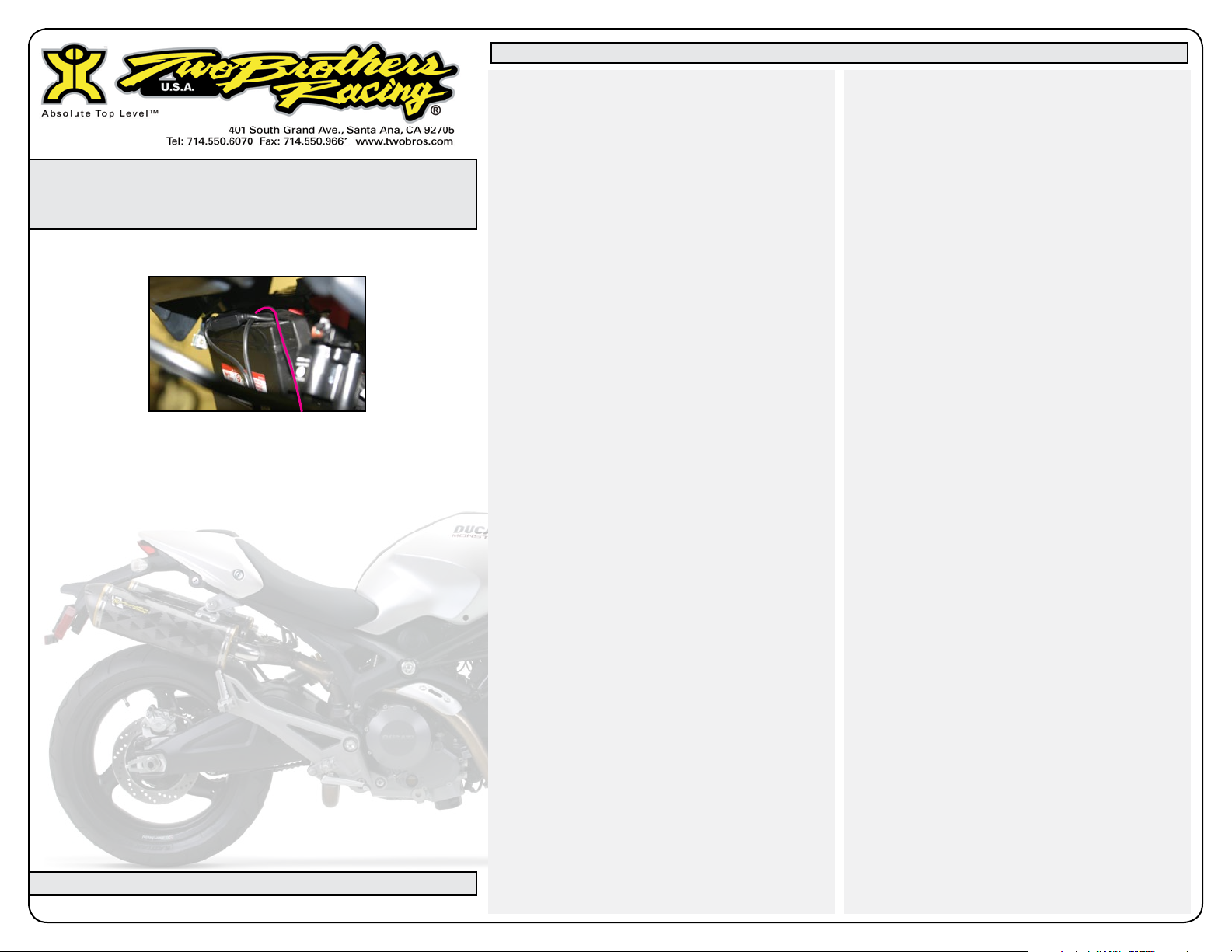
Attach ground wire to (-) terminal of battery. (fig.10)
12.
13.
14.
15.
Fig 10
Make sure all wires are secured.
NOTE: Re check your wire routing and JUICE BOX™ location and
make certain that in no way the wires can come into contact with
any moving parts or high heat source and that the JUICE BOX™
is mounted in a way as to not cause a handling problem with the
machine.
Re-install fuel tank and seat assembly.
Start the bike. The green LED should now be scrolling for about
3-5 seconds and then go to 1 or more steady green LED’s or
a single slow flashing green LED. If the number 1 green and
number 8 red LED continue flashing after startup, an injector
wiring error is indicated. Re-check the wires from the JUICE
BOX™ and make sure they are connected to the proper wires
of your bike’s stock harness. MAKE SURE you have the correct
connectors selected in the stock harness. DO NOT PROCEED
UNLESS ABOVE CONDITIONS ARE MET.
It is recommended that the pre-programmed settings of
1.
the Juice Box™be used. However, the Juice Box™ can be
adjusted to suit different engine modifications, states of
tune and environmental conditions. To begin this process,
press the mode button. To enter each successive mode, just
press the mode button again. Note that every mode will
be identifiable by the color(s) of the flashing LED(s) on the
LED display.
by an LED color or color combination.
as follows, respectively: Green, Yellow, Red, Green-Blue,
Yellow-Blue and Red-Blue.
2.
You are now ready to manually program each mode.
Consult the base settings supplied with the unit.
To program the Juice Box™, the bike must be running in
order to supply power to the Juice Box™.
Simply press the mode button to activate the first mode.
If at anytime you stay in an adjustment mode for longer
than 5 seconds without pressing any buttons, the Juice
Box™ will exit the adjustment mode and will return to the
operational mode.
To save settings in a particular mode press the MODE
button which goes to the next adjustable mode or wait for
the Juice Box™ to exit back to the operational mode.
The settings in each mode are adjusted by pressing the
(+) and (-) buttons located on the right and left side of the
mode button, respectively. For easy reference, the LEDs are
numbered 1 through 8. However, the LEDs can be adjusted
to the following positions: 0.5, 1, 1.5, 2, 2.5, 3, 3.5, 4, 4.5, 5,
5.5, 6, 6.5, 7, 7.5, 8. For example, in a particular mode, if LED
4 is flashing then the LED display is set to 4 in that mode. If
the (+) button is pressed once then LEDs 4 and 5 will flash
simultaneously and the LED display is set to 4.5. If the (+)
button is pressed once again, only LED 5 will flash and the
LED display is set to 5. The LED display can also be set
to 0.5 by pressing the (-) button and scrolling the colored
LED to position 1 and then pressing the (-) button once
more until the LED in position 1 is flashing twice as fast as
normal.
I.
application. Adjusting the Green LED in this mode has no
result.
II.
additional amount of fuel added during acceleration. A
flashing yellow LED should appear on the LED display. To
add more fuel, scroll the flashing yellow LED to the right
using the (+) button. To add less fuel, scroll the flashing
yellow LED to the left using the (-) button. If you set the
flashing yellow LED to the 0.5 position on the LED display,
no fuel will be added to the stock fuel curve.
There are six modes that are distinguished
The 6 modes are
The first mode (Green Mode) is not used in this
The second mode (Yellow Mode) represents an
III. The third mode (Red Mode) represents an additional
amount of fuel added during full throttle conditions. A
flashing red LED should appear on the LED display. To add
more fuel, scroll the flashing red LED to the right using the
(+) button. To add less fuel, scroll the flashing red LED to
the left using the (-) button. If you set the flashing red LED
to the 0.5 position on the LED display,
to the stock fuel curve.
Note: If the flashing green, yellow and red LEDs in modes
1 through 3 (Green, Yellow and Red) are set to the 0.5
position on the LED display then the Juice Box™ will not
add any fuel to the bike’s stock fuel curve. This setting will
essentially turn off the Juice Box™ even though it is still
attached to the bike’s fuel injection system. The bike will
run as though the Juice Box™ is not installed. The Juice
Box™ LEDs will still operate normally even though no fuel
is being added.
IV.
The fourth mode (Green-Blue Mode) is not
applicable for this particular model.
V.
The fifth mode (Yellow-Blue Mode) is an adjustment
to determine the time when the acceleration/Yellow Mode
fuel amount turns on. A flashing yellow LED appears on
the LED display while at the same time a flashing blue LED
appears on the 8th LED. To increase the sensitivity and
therefore cause the Yellow Mode fuel to turn on sooner,
scroll the flashing yellow LED to the left using the (-) button.
To decrease the sensitivity and therefore cause the Yellow
Mode fuel to turn on later, scroll the flashing yellow LED to
the right using the (+) button.
VI.
The sixth mode (Red-Blue Mode) is an adjustment
to determine the time when the full throttle/Red Mode fuel
amount turns on. A flashing red LED appears on the LED
display while at the same time a flashing blue LED appears
on the 8th LED. To increase the sensitivity and therefore
cause the Red Mode fuel to turn on sooner, scroll the
flashing red LED to the left using the (-) button. To decrease
the sensitivity and therefore cause the Red Mode fuel to
turn on later, scroll the flashing red LED to the right using
the (+) button.
no fuel will be added
Cleaning
If the unit requir es cleaning , use a clo th that is only lightl y dampened with water or mild det ergent.
Page 3

Two Brothers Racing
Juice Box™ - Fuel Controller
2009 Ducati 696 Installation & Operation Manual
Part # 0 08-249
Operation Manual - JUICE BOX™ Settings
(2009) Ducati 696 Pre-set Settings: 696 baseline settings with stock air filter and TBR DUAL slip-on exhaust system.
(G=0.5, Y=4, R=4, GB=N/A, YB=4, RB=4)
Mode 1 - Green
Mode 4 - Green/Blue Mode 5 - Yellow/Blue Mode 6 - Red/Blue
Mode 2 - Yellow Mode 3 - Red
For Race Use Only
The Juice Box™ is legal ONLY for closed course race vehicles. The Juice Box™ is not
applicable, nor inteded for use on EMISSIONS CONTROLLED street, highway or off-road
vehicles. The Juice Box™ is not applicable, nor inteded for use on aircraft.
For additional settings please visit our website at www.twobros.com.
 Loading...