

THE WORLD MODELS
MANUFACTURING CO., LTD.
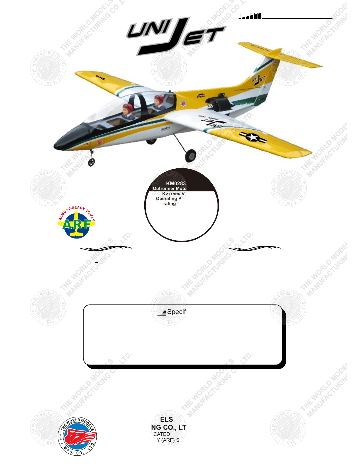
FACTORY PRE-FABRICATED
ALMOST-READY-TO-FLY (ARF) SERIES
MADE IN CHINA
www.theworldmodels.com
Wing Span
Wing Area
Flying Weight
Fuselage Length
36 in / 920 mm
225 sq in / 14.5 sq dm
28 oz / 790 g
32.5 in / 830 mm
Warning! This model is not a toy.
It is designed for maximum performance. Please seek advice if one is not familiar with this kind
of electric powered precision model. Operating this model without prior preparation may cause
injuries. Remember, safety is the most important thing. Always keep this instruction manual at
hand for quick reference.
Outrunner Motor
Requires : 4-channel radio w/ 4 micro servos,
30A (burst 35A) brushless ESC, 3 cells
11.1V 15C discharge 2100 mAh Li - Po
battery & charger.
Specifications
*Specifications are subject to change without notice.*
INSTRUCTION MANUAL
HIGH
PERFORMANCE
KM0283110KM0283110
Outrunner Motor Included!
Kv (rpm/ V) 3600
Operating Power 350 W
Operating Voltage 6-15 V
Operating Current 30 A
Peak Current 35 A (max 15 s)
Shaft Diameter 3 mm (0.118”)
Diameter 28 mm (1.10”)
Length 31 mm (1.22”)
Weight 60 g (2.1 oz)
P. 1
INDEX
BEFORE YOU BEGIN
P. 1
PARTS LIST
P.2
SAFETY PRECAUTIONS
P.10
BEFORE YOU BEGIN
Cut off shaded portion.
Ensure smooth non-binding
movement while assembling.
Apply instant glue
(C.A.glue, super glue.)
Assemble left and right
sides the same way.
Peel off shaded portion
covering film.
Pay close attention here!
Apply epoxy glue.
Must be purchased separately !
Drill holes with the specified
diameter (here: 3mm).
ASSEMBLY
P.3-P.10
Check all parts. If you find any defective or missing parts contact your local dealer. Please DRY FIT
and check for defects for all parts that will require CA or Epoxy for final assembly. Any parts you
find to be defective after the gluing process may be difficult to remove for warranty replacement. The
manufacturer will replace any defective parts, but will
not
extend to the parts that are good before
gluing to defective parts during assembly.
Warranty will not cover any parts modified by customer.
Read through the manual before you begin, so you will have an overall idea of what to do.
Symbols used throughout this instruction manual comprise of the following : -
1
2
3
Pierce the shaded portion
covering film.
3mm
Do not overlook this symbol !
Warning!
Apply thread locker
P.2
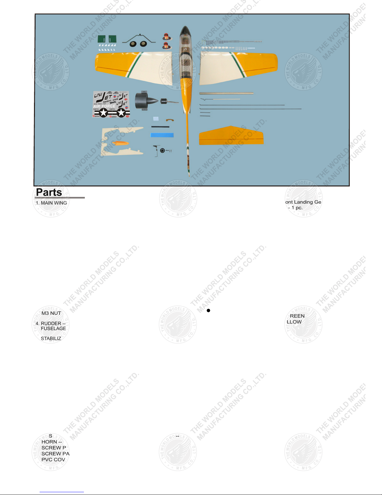
Parts List
1. MAIN WING -- 1 pair
2. SERVO MOUNTING PANEL -- 1 pair
PUSHROD Ø1.4x50mm w/ Threads (For Aileron Servo) -- 2 pcs
STRAPER -- 2 pcs
FUEL TUBE
d2xD4x4mm -- 4 pcs
CLEVIS -- 2 pcs
HORN -- 2 sets
SCREW PM2x16mm -- 4 pcs
SCREW PA1.7x8mm -- 8 pcs
3. DUCTED FAN PROPULSION UNIT WITH 28/31 MOTOR -- 1 set
PLYWOOD 3x67.8x217.8mm -- 1 pair
CABLE TIE -- 4 pcs
SOCKET HEAD SCREW M3x6mm -- 4 pcs
SCREW PM2x5mm -- 3 pcs
SCREW PM3x12mm -- 4 pcs
SCREW PWA2.3x8mm -- 4 pcs
WASHER d3xD7mm -- 4 pcs
M3 NUT -- 4 pcs
4. RUDDER -- 1 pc.
FUSELAGE -- 1 pc.
5. STABILIZER & ELEVATOR -- 1 set
6. MAIN LANDING GEAR -- 1 set
LANDING WIRE STRAPS (PL4114030) -- 2 pcs
MAIN WHEEL
Ø40mm -- 2 pcs
COLLAR Ø2.6mm w/ set screw -- 4 sets
SCREW PA2x8mm -- 4 pcs
7. FRONT LANDING GEAR -- 1 set
PLASTIC COLLAR d1.1xD5x2mm -- 2 pcs
FRONT WHEEL Ø23mm -- 1 pc.
SCREW PA2x8mm -- 2 pcs
8. PUSHROD Ø1.2x440mm
w/ Threads
(For Rudder Servo) -- 1 pc.
HORN -- 1 set.
SCREW PM2x12mm -- 2 pcs
9. PUSHROD Ø1.2x533mm
w/ Threads
(For Elevator Servo) -- 1 pc.
HORN -- 1 set
SCREW PM2x8mm -- 2 pcs
SCREW PA2x5mm -- 3 pcs
PVC COVER 0.5mm -- 1 pc.
10. PUSHROD
Ø0.8x206mm (For Front Landing Gear) -- 1 pc.
PLASTIC TUBE d2xD3x140mm -- 1 pc.
CLEVIS (d1.2mm) -- 2 pcs
FUEL TUBE d2XD4x4mm -- 2 pcs
PLYWOOD 2x9.4x15mm -- 1 pc.
BATTERY TIE 200mm -- 1 pc.
SPONGE 10x50x150mm -- 1 pc.
11. EYE SCREW PA2.5x10x23mm -- 2 pcs
WING TUBE d9.6x284mm -- 1 pc.
RUBBER BAND D30x1mm -- 2 pcs
12. COOKPIT -- 1 pc.
PILOT (PC101042A) -- 2 pcs
13. DECAL -- 1 set
COVERING:- LIGHTEX SGX 540 PEARL GREEN
LIGHTEX SGX 331 CUB YELLOW
LIGHTEX SGX 100 WHITE
P.3
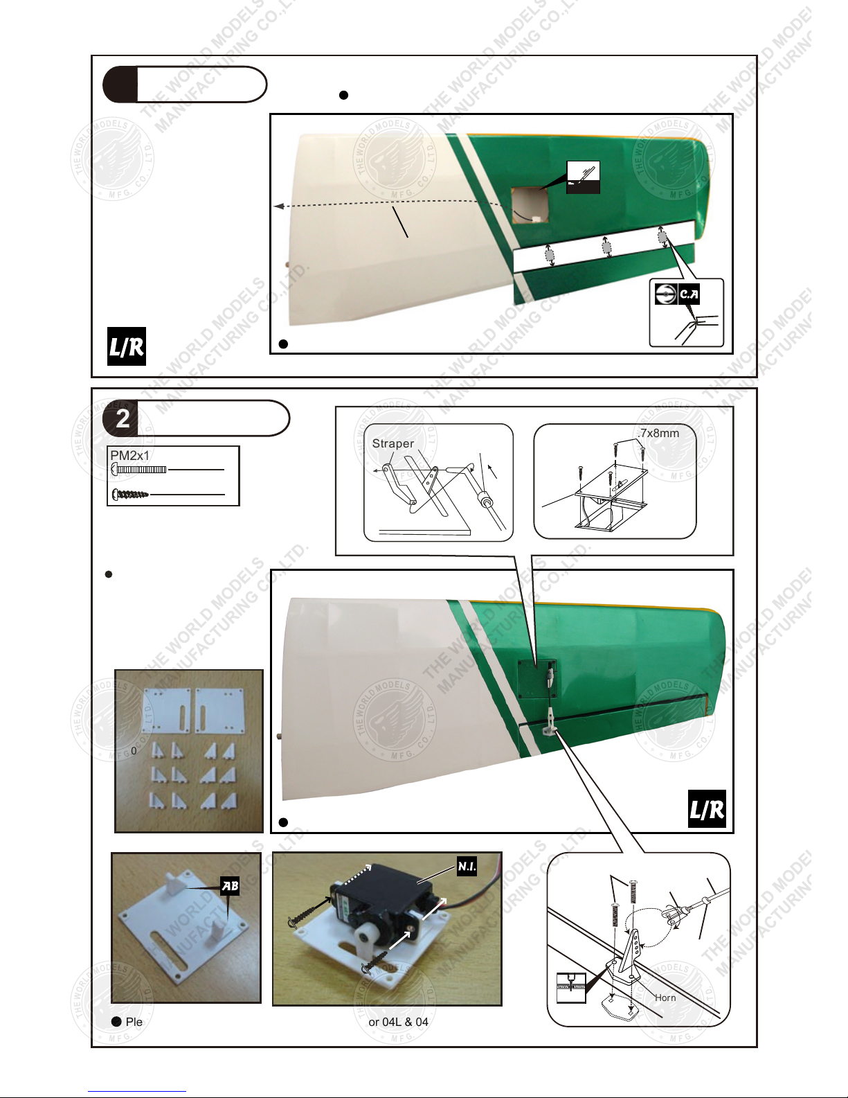
Main Wing
1
Aileron Servo
2
Aileron Servo Lead
Ø1mm pilot holes for World
Models tri-horn are pre-drilled.
Please look for pin-hole marks
at under side of control surfaces.
4
8
PA1.7x8mm Screw
PM2x16mm Screw
Str aper
Fuel Tube
d2xD4x4mm
Please choose either 02L & 02R or 03L & 03R or 04L & 04R that suits your servo.
02L
03L
04L
02R
03R
04R
Apply instant type CA glue to both sides of each hinge.
Bottom View
Bottom View
Fuel Tube
Clev is
PM2x 16mm
Horn
Pushrod
Ø1.4x50mm
d2xD4x4mm
PA1.7x8mm
2mm

P.4
Ducted Fan Propulsion Unit with 28/31 Motor
3
3
4
4
4
4
PM3x12mm Screw
d3xD7mm Washer
PM2x5mm Screw
PWA2.3x8mm Screw
M3x6mm Socket Head Screw
M3 Nut
Make sure TWM logo on ducted
fan stay on left side of fuselage.
Center Line
1
2
3
5
4
Make sure rotating motor casing
is not in contact with wiring or anything.
PM2x5mm
PM3x12mm
PM3x12mm
M3 Nut
M3x6mm
Rear View
4
PWA2.3x8mm
Cable Tie
1. 5m m
d3xD7mm
Washer
d3xD7mm
Washer
Plywood
3x67.8x217.8mm
TWM
TWM
TWM
TWM
TWM
6
30A Brushless ESC

Stabilizer & Elevator
4
Rudder
5
(Stabil izer)
(Main Wi ng)
B B'
B=B'
P.5
Completed
Completed
Apply instant type CA glue to both sides of each hinge.
Temporary install the main
wing, adjust leveling of the
stabilizer to make it as
parallel to the main wing as
possible.
Bottom View
Main Landing Gear
6
PA2x8mm Screw
2.6mm C o llar
4
4
PA2x8m m
1mm
Front
A A'
A= A'
C=C'
C
C'
3mm Set Screw
2.6mm Collar
Apply instant type CA glue to both sides of
each hinge.
Bottom View

P.6
Front Landing Gear
7
Rudder Pushrod
PA2x8mm Screw
2
PM2x12mm Screw
2
Plas tic Collar
d1.1xD5mm
1. 3m m
PA2x8m m
1.5 mm
8
Elevator Pushrod
9
PA2x5mm Screw
3
PM2x8mm Screw
Horn
2
PA2x5m m
1. 5m m
2mm
Bottom View
Bottom View
Ø1mm pilot holes for World Models horn are pre-drilled. Please look for
pin-hole marks at side of control surfaces.
Ø1mm pilot holes for World Models horn are pre-drilled. Please look
for pin-hole marks at under side of control surfaces.
2mm
Rudder Pushrod
Ø
1.2x440mm
Horn
PM2x12mm
120mm
55mm
PM2x8mm
Elevator Pushrod
Ø1.2x533mm
Ø1mm pilot hole is pre-drilled. Please look for pin-hole marks at
under side of fuselage.

P.7
10
Radio Equipment
Install and arrange the equipment as
shown in the picture.
Front Landing Gear
Front Landing Gear
Pushrod
Front Landing Gear
Pushrod
Ø0.8x206mm
Front
Plywood
2x9.4x15mm
w/ Plastic Tube
d2xD3x140mm
Elevator Servo
Elevator Pushrod
Ø1.2x533mm
Fuel Tube
d2xD4x4mm
Rudder Pushrod
Ø1.2x440mm
Rudder Servo
Fuel Tube
d2xD4x4mm
Clevis
Clevis
Bottom View
Front
Battery
Battery Tie
Sponge
Receiver
30A Brushless ESC Lead

Main Wing
11
Lead To Aileron Servo
Wing Tube Ø9.6x284mm
Rubber Band
Eye Screw
PA2.5x10x23mm
1. 5 mm
P.8
Front
Front
Bottom View

P.9
Wing Setting
13
Adjust the wing and fuselage configuration as shown in the diagrams.
A=A' B=B' C=C'
A
A'
B
B'
C
C'
Cookpit
12
Completed
Pilot

P.10
E2720 709
C.G.
15
Important Safety Precautions
# First time flyer should never fly by himself / herself. Assistance from experienced flyer is
absolutely necessary.
# Pre-flight adjustment must be done before flying, it is very dangerous to fly a badly
pre-adjusted aircraft.
# is designed for high speed flying. Too low an air speed during take off or landing
may canuse tip stall. Point the UniJet towards the wind, use full throttle and let the UniJet
gain enough ground speed before pulling the elevator gently for take off. For landing,
approach against the wind, maintain power to the ducted fan to keep enough air speed
before touch down.
# Make sure the air field is spacious, never fly the plane too close to people and neverget
too close to a running propeller.
# If you find wrinkles on the covering as a result of weather changes, you can use hot iron
to remove the wrinkles. Please begin with lower temperature setting and gradually raise
the temperature until the wrinkles are gone. Too hot an iron may damage the covering.
# Check and re-tighten up all factory assembled screws, use thread locker if necessary.
Warning!
The ideal C.G. position is 57mm ( 2.25in ) behind the leading
edge measured at where the wing meets the fuselage. In order to obtain
the C.G. specified, add weight to the fuselage or move the battery
position. Check the C.G. before flying.
57mm
C.G.
2.25in
Control Throws
14
6mm
6mm
El e vator
12mm
12mm
Rudder
6mm
6mm
Ailerons
Adjust the control throws as shown in the diagram. These throws are good for general
flying. You can adjust according to your personal preference.

http://www.theworldmodels.com
E2720 709
 Loading...