

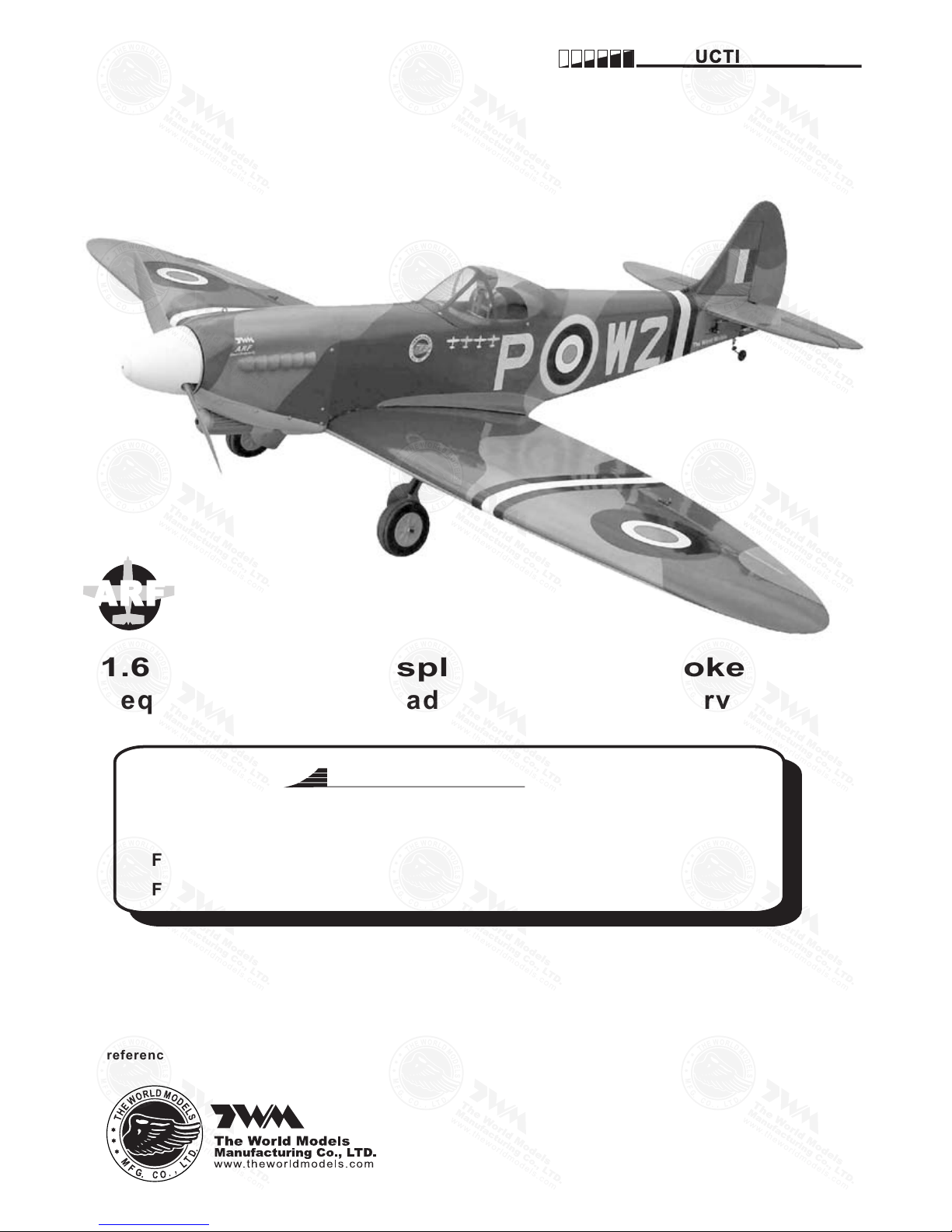
1.60 cubic inch displacement 2-stroke(glow)
Requires: 6 channel
2 low profile retract servos
- radio w/ 7 standard servos and
Specifications
Wing Span
Wing Area
Flying Weight
Fuselage Length
80 in / 2030 mm
1138 sq in / 73.4 sq dm
13 lb / 5850 g
68 in / 1730 mm
It is design ed f or m aximum performan ce. Pleas e seek a dvice if one is not famil iar with this kin d of
engi ne powered preci sion mo del. Oper ating t his model w ithou t prior pre parat ion may cause inju ries.
Reme mber, safe ty is the mos t importa nt thing. Alway s ke ep this ins truct ion manua l at h and for qui ck
refe rence .
Warning! This model is not a toy.
INSTRUCTION MANUAL
SPITFIRE G.S.
E
A
D
R
-
Y
T
-
T
S
O
O
-
F
M
L
L
Y
A
AR F
* Spec ifica tions are s ubjec t to change w ithou t notice.*
FACTORY PRE-FABRICATED
ALMOST-READY-TO-FLY (ARF) SERIES
MADE IN CHINA
SPITFIRE G.S.
P. 1
P. 3 - 12
Check all parts. If you find any defective or missing parts contact your local dealer. Please DRY FIT
and check for defects for all parts that will require CA or Epoxy for final assembly. Any parts you
find to be defective after the gluing process may be difficult to remove for warranty replacement. The
manufacturer will replace any defective parts. but will
not
extend to the parts that are good before
gluing to defective parts during assembly.
IN DE X
BEFORE YOU BEGIN
PARTS LIST
ASSEMBLY
SAFETY PRECAUTIONS
P. 1
P. 2
P. 12
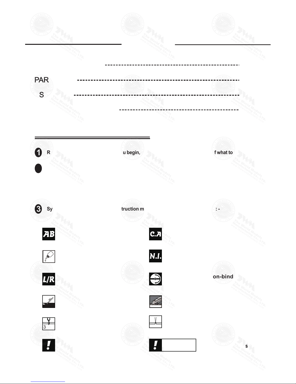
BEFORE YOU BEGIN
Read through the manual before you begin, so you will have an overall idea of what to do.
Symbols used throughout this instruction manual comprise of the following : -
1
2
3
3mm
Do not overlook this symbol!
Cut off shaded portion.
Peel off shaded portion
covering film.
Pay close attention here!
Pierce the shaded portion
covering film.
Must be purchased separately!
Drill holes with the specified
diameter (here: 3mm).
Ensure smooth non-binding
movement while assembling.
Apply instant glue
(C.A.glue, super glue.)
Assemble left and right
sides the same way.
Apply epoxy glue.
Apply thread locker
Warning!
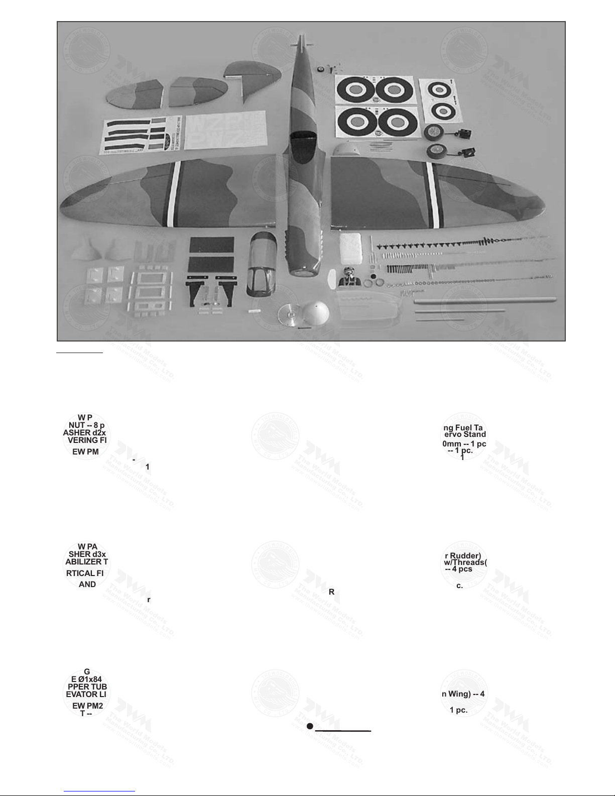
Parts List
P.2
1.MAIN WING -- 1 pair
2.RETRACTABLE LANDING GEAR -- 1 set
RETRACTABLE LANDING GEAR COVER -- 1 set
PUSHROD Ø1.8x45mm(For Retractable) -- 2 pcs
MAIN WHEEL Ø103mm -- 2 pcs
COLLAR Ø5.7mm w/set screw -- 4 sets
SCREW PM2x8mm -- 8 pcs
SCREW PWA2.3x8mm -- 8 pcs
M2 NUT -- 8 pcs
WASHER d2xD5mm -- 16 pcs
COVERING FILM 45x75mm -- 2 pcs
3.SCREW PM2x14mm -- 6 pcs
SCREW PM2x25mm -- 6 pcs
SCREW PWA2x12mm -- 16 pcs
FUEL TUBE Ø6x5mm -- 8 pcs
CLEVIS -- 4 pcs
STRAPER -- 4 pcs
TRI-HORN M3x14mm(L)(For Aileron & Flap) -- 4 sets
PUSHROD Ø1.8x100 w/Threads(For Aileron Servos) -- 2 pcs
PUSHROD Ø1.8x110 w/Threads(For Flap Servos) -- 2 pcs
SERVO MOUNTING PANEL 2x68x78mm -- 2 pairs
4.STABILIZER & ELEVATOR -- 1 set
FUSELAGE -- 1 pc.
SCREW PA3x12mm -- 2 pcs
WASHER d3xD7mm -- 2 pcs
STABILIZER TUBE Ø9.5x256mm -- 1 pc.
5.VERTICAL FIN & RUDDER -- 1 set
6.TAIL LANDING GEAR -- 1 set
TAIL WHEEL Ø30mm -- 1 pc.
COLLAR 2.6mm w/set screw -- 1 set
SCREW PA3x12mm -- 2 pcs
7.SCREW PM2x25mm -- 6 pcs
SCREW PWA2x12mm -- 6 pcs
FUEL TUBE Ø6x5mm -- 4 pcs
STRAPER -- 2 pcs
CLEVIS -- 2 pcs
TRI-HORN M3x14mm(L)(For Elevator) -- 2 sets
PUSHROD Ø1.8x110mm w/Threads(For Elevator) -- 2 pcs
RIGGING Z BEND Ø1.8x27mm(For Elevator) -- 2 pcs
WIRE Ø1x840mm(For Elevator) -- 2 pcs
COPPER TUBE Ød2.5xD3.2x8mm -- 2 pcs
ELEVATOR LINKAGE Ø6x88mm -- 1 set
8.SCREW PM2x30mm -- 3 pcs
M2 NUT -- 3 pcs
FUEL TUBE Ø6x5mm -- 2 pcs
CLEVIS -- 2 pcs
RIGGING COUPLER Ø1.8x2.7mm w/Threads(For Rudder) -- 2 pcs
WIRE Ø1x1040mm(For Rudder) -- 2 pcs
TRI-HORN M3x14mm(L)(w/o-Base For Rudder) -- 2 sets
COPPER TUBE d2.5xD3.2x8mm(For Rudder) -- 2 pcs
9.ENGINE MOUNT PL511120 -- 1 set
SCREW M6x30mm -- 4 pcs
WASHER d6xD15mm -- 4 pcs
BLIND NUT M6xD18mm -- 4 pcs
WOODEN DOWEL Ø7.5x9mm(For Firewall) -- 4 pcs
10.FUEL TANK 800cc -- 1 set
PLYWOOD 3x41x125mm(For Fixing Fuel Tank) -- 1 pc.
BALSA 8x8x41mm(For Throttle Servo Stand) -- 2 pcs
11.THROTTLE PUSHWIRE Ø1.2x350mm -- 1 pc.
w/Plastic Tube d2xD3x170mm -- 1 pc.
ANTI-VIBRATION MOUNT 4C-120-3 -- 1 set
INCLUDE:SOCKET HEAD SCREW M4x35mm -- 4 pcs
SCREW KM3x20mm -- 8 pcs
WASHER d4xD12mm -- 8 pcs
NYLON INSERT LOCK NUT M3 -- 8 pcs
NYLON INSERT LOCK NUT M4 -- 4 pcs
ALUMINUM PLATE 2x12x75mm(For Engine Mount) -- 1 pc.
12.LINKAGE CONNECTOR Ø2.1mm -- 3 sets
13.PLYWOOD 6x60x126mm(For Elevator Servo) -- 1 pc.
PLYWOOD 6x60x125mm(For Rudder Servo) -- 1 pc.
BALSA 8x8x60mm(For Elevator & Rudder Servos Stand) -- 4 pcs
SPONGE 60x70x125(For Radio Equipment) -- 1 pc.
FUEL TUBE Ø6x5mm -- 2 pcs
CLEVIS -- 2 pcs
RIGGING Z BEND Ø1.8x27mm(For Rudder) -- 2 pcs
RIGGING COUPLER Ø1.8x27mm w/Threads(For Elevator) -- 2 pcs
COPPER TUBE Ø2.5xD3.2x8mm -- 4 pcs
14.COWLING -- 1 pc.
TRANSPARENT 3D TEMPLATE -- 1 pc.
SCREW PWA2.6x12mm -- 4 pcs
SILICON GROMMET d1.5xD6.5mm -- 4 pcs
QUICK RELEASE NYLON RIVET PL1208042 -- 10 pcs
SCREW KA2.3x8mm -- 10 pcs
PLASTIC SPINNER(w/alu.back plate) Ø114mm -- 1 set
15.SCREW PM3x75mm -- 2 pcs
WASHER d3xD17mm -- 8 pcs
WASHER d4xD15mm -- 2 pcs
SCREW PM4x40mm -- 2 pcs
SOCKET HEAD SCREW M3x15mm -- 2 pcs
NYLON INSERT LOCK NUT M3 -- 2 pcs
M3 NUT -- 2 pcs
WING TUBE Ø25.4x670mm -- 1 pc.
WING TUBE Ø9.5x325mm -- 1 pc.
WING PROTECTION -- 1 pc.
ALUMINUM PLATE 2mm(For Main Wing) -- 4 pcs
16.CANOPY -- 1 pc.
DOUBLE SIDED TAPE 6x800mm -- 1 pc.
SCREW PWA2.3x8mm -- 4 pcs
SILICON GROMMET d1.5xD6.5mm -- 4 pcs
PILOT PC001103B -- 1 set
17.DECALS:A154DEC -- 1 set
COVERING:--
TOUGHLON STL 100 WHITE
TOUGHLON STL 203 LIGHT GRAY
TOUGHLON STL 351 DARK BLUE
TOUGHLON STL 340 OLIVE DRAB
P.3
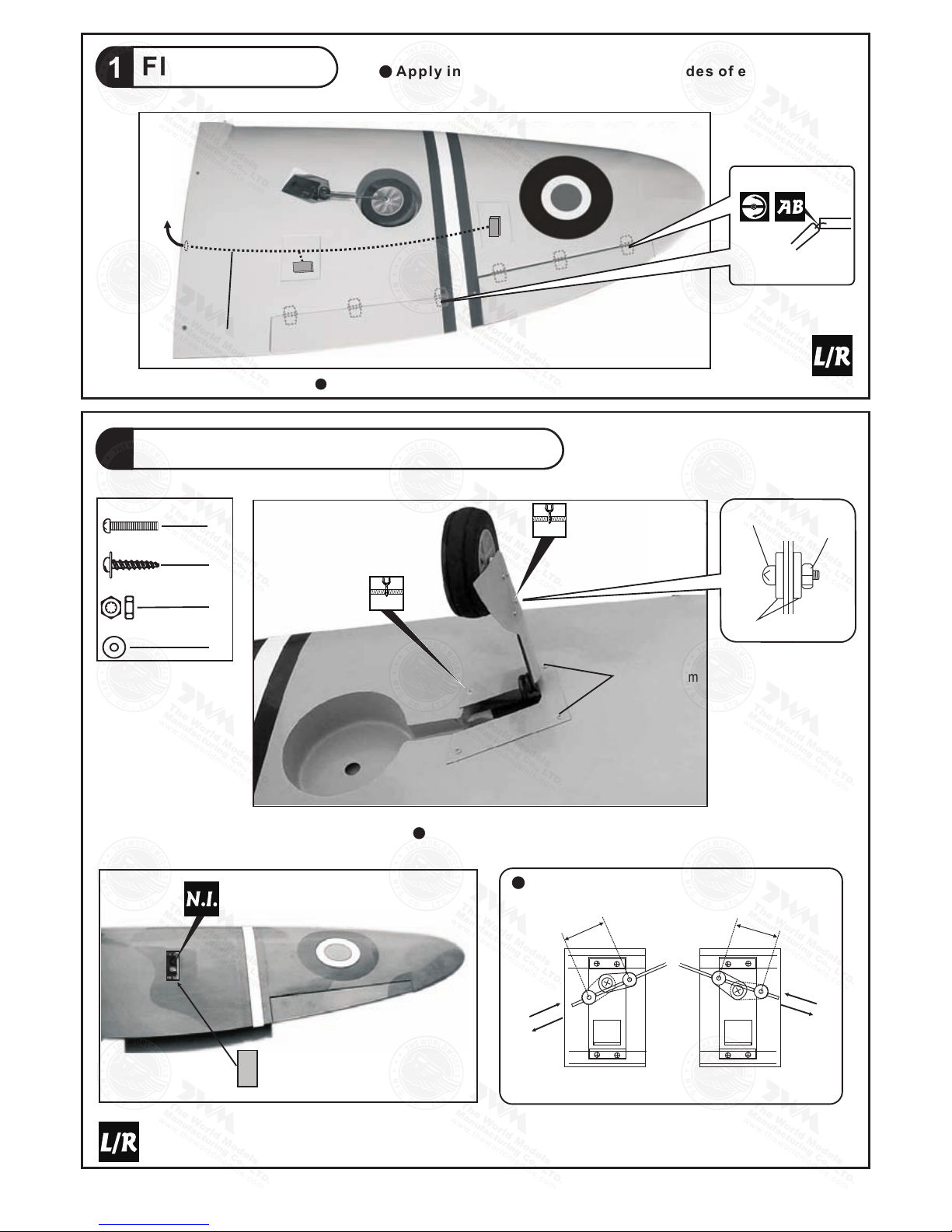
Flap & Aileron
1
Landing gear & Retract Servos
2
Bottom View
PM2x8mm Screw
8
M2 Nut
8
16
d2xD5 Washer
Covering Film
8
PWA 2.3 8mm Screwx
PWA 2 .3x8mm
d2xD5 mm
Was her
PM2x8 mm
M2 NUT
L
Retract Servos
R
Wheel
Down
Wh
eel
up
Wheel
Down
Wheel
up
32mm Travel
32mm Travel
Bottom View
Apply i n s tant t y p e CA glue t o bo t h sides o f each h i n ge.
Aileron Servo lead
2mm
1mm
Pre-glued
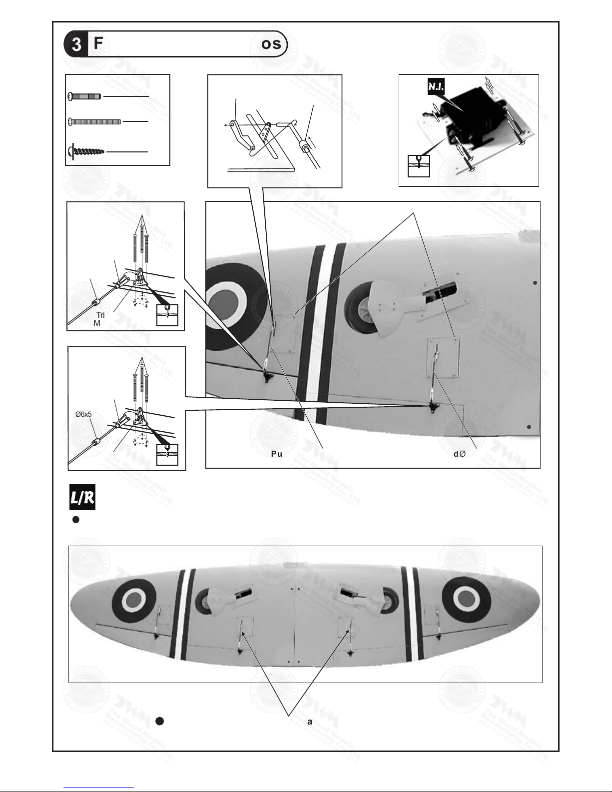
Flap & Aileron Servos
3
Æ1mm pilot holes for World Models tri-horn are pre-drilled. Please look for pin-hole marks at under
side of control surfaces.
Push R od 1.8x110mmØ
PM2x14mm Screw
PWA 2x12 mm Screw
PM2x25mm Screw
6
6
The existing slot s are f or 2 channels (mixing) opera tio n of the flaps.
Stra per
Push R od 1.8x100 mmØ
P.4
PWA2x 12mm
16
PM2x1 4m m
1.5mm
Fuel Tube
Ø6x5mm
Tri-horn
M3x14mm(L)
Clevis
PM2x25mm
2mm
Fuel Tube
Ø6x5mm
Tri-horn
M3x14mm(L)
Clevis
2mm
Fuel Tube
Ø6x5mm

P.5
Stabilizer & Elevator
4
A
A'
A=A'
PA3x12mm Screw
2
d3xD7mm Washer
2
PA3x12mm
Stab ilize r Tube
D9.5 x256m m
d3xD7mm
97mm
60mm
Completed
Pre-glued
d3xD7mm
PA3x12mm
5
A A'
A=A'
Completed
pre- glued
Vertical Fin & Rudder
2mm

P.6
Elevator Pushrod
7
PM 2x25 mm Screw
PWA 2x12 mm Screw
6
6
3 x 3 m m S e t S c r e w
1
Pushrod
Ø1.8x110mm
Tail Landing Gear
6
1.5mm
PA3x12mmScrew
3mm Set Screw
2.6mm Collar
2
1
1
PM2x25mm
1mm pilot holes for World Models tri-horn are pre-drilled. Please look for pin-hole marks at under side of control surfaces.
Elevator Linkage
2.5mm
Stra pe r
Fuel Tube
Ø6x5mm
Fuel Tube
Ø6x5mm
Tri-horn
M3x14mm(L)
Clevis
2mm
PWA 2 x 12mm
Pushrod
Ø1.8x27mm
Copper Tube
3mm Set Screw
Elevator Pullwire
PWA 2 x 12mm
PWA 2 x 12mm
Plastic
Collar
Adjust clearance of
linkage by adding or
removing washer
Clamp the copper tube
1mm
TWM PL8210010
CLEVIS WRENCH
3mm Set Sc re w
PA3x12mm

P.7
9
!
Blind nuts are off- cen tered to keep
the spinner at the fu sel age axis.
Engine Mount
A: Inverted mount
Wooden dowel
Ø7.5x9mm
M6x30mm Screw
4
4
4
d6xD15mm Washer
M6xD18mm Blind Nut
Engine Mou nt
PL5111 20
B:Inclined mount
Ø1mm pilot holes for World Models tri-horn are pre-drilled. Please look for pin-hole marks at
side of control surfaces.
Rudder Pullwire
8
PM 2x30mm Screw
3
M2 Nut
3
PM2x30mm
M 2 N ut
Clevis
Rigging Coupler
Ø1.8x27mm
Fuel Tube
Ø 6x5mm
2mm
Ring
»163mm
»38mm
Copper Tube
d6xD15 mm
M6x30m m
M6xD18 mm
Apply thr ead locker to screws .
To seal off unused holes.

P.8
Engine
Illustration is for inverted mounting. You can
mount the engine upright or sideways simply
by rotation the engine mount. Thrust angles
will not be affected.
Thro ttle Pu shwire
Ø1.2 x350m m
d2xD 3x170 mm
Plas tic Tube
M4 Nyl on Inse rt Lock Nut
11
152mm
6.0in
Install Engi ne po sition
M 4 x 3 5 m m S c r e w
M4 Nylon Insert Lock Nut
4
8
4
8
d4xD12mm Wa sher
KM3x20mm Wa sher
M3 Nylon Insert Lock Nut
8
ANTI-VIBRATION MOUNT INSTALLATIO N
M3
KM3x 20 mm
Counter Sink
4.1mm
5.1mm
3.2mm
M a ke s u r e t h e ro u nd ed
ed g es ar e faci ng t he sh o ck
ab s or b in g S IL ICO N PAD.
d4xD 12mm
M4x 35 mm
3 . 2 m m
3
Fuel Tank
10
Inst all Ply wood 3x41 x125m m
Plyw ood
3x41 x125m m
(For f ixing f uel tank)
Fuel Tank
800c c
Bott om View
Fuel Tank
800c c
Bals a
8x8x 41mm

P.9
Servo Set
Elev ator Se rvo
Rudd er Serv o
Plyw ood
Bals a
6x60 x125m m
8x8x 60mm
8x8x 41mm
Plyw ood
3x41 x125m m
3x3mm Set Screw
Linkage Connect or
M2 Nut
2mm Washer
3
3
3
3
LINK AGE CON NECTOR
Servos
13
1mm
Install and arrange the servo as shown in the diagram.
Thro ttle Se rvo
Wire 1 x 1040m mØ
Wire 1x840 mmØ
Bals a
Rudd er Pull Wir e
Front
Thro ttle pu shrod
Ø1.2 x350m m
Bottom View
12
Elevator Pull Wire
Fuel Tub e
Ø6x5m m
Copper Tube
Press do wn t he c en ter
1/3 port io n
Please refer to att ach ed sheet for linkage connect or in stallation.
Incl uded with the radi o Set.
Throttl e Pushwire
3x3mm Set S crew
Throttl e Servo.
2mm
2mm
Washer
M2 Nut
2mm
Washer

P.10
Main Wing
PM3x75mm Screw
PM4x40mm Screw
M3 Nylon Insert Lock Nut
M3x15mm Screw
8
2
2
2
2
d3xD7mm Washer
2
M3 Nut
2
d4xD15mm Washer
PM4x 40mm
d4xD 15mm
Wing Pro tecti on
Bottom View
Bottom View
Wing Tu be D25.4x 670mm
Wing Tu be D9.5x 32 5mm
Cowling
PWA2.6 x 12 mm Screw
d1.5 x D6.5 mm Silicon Grommet
Firs t inser t the gromm et to the c owling th en appl y screw.
15
4
4mm
KA 2.3 x 8 mm
PWA 2. 6 x 12 m m
d1.5 x D6. 5 mm
Silico n Gr om me t
14
PM3x75mm
d3xD 7m m
d3xD 7m m
Nylon Insert Lock Nut
M3
M3x15mm
d3xD 7m m
d3xD 7m m
M3
Up
Down
Quick Release Nylon Rivet
10
KA 2.3 x 8 mm
Screw
10
4
Quick Release Nylon Rivet

2
1
PWA2. 3 x 8 mm
PWA2.3x8 mm Screw
d1.5 x D6.5 mm Silicon Grommet
4
4
16
Canopy
First insert the grommet to the canopy then apply screw.
Sili con Gro mmet
d1.5 xD6.5 mm
Apply double-sided tape
Pilo t
Adju st the wi ng and fuse lage co nfigura tion
as sho w in the diagrams.
B
B'
C C'
A = A ' B = B ' C = C '
Wing Setting
17
A A'
P.11
1mm

P.12
Adju st the co ntrol thr ows as sh own in the di agram .
Thes e throws ar e go od for gene ral flyin g. You can
adju st acco rding to yo ur pers onal preferenc e.
The ideal C.G. position is 116mm ( 4.6in ) behind the leading
edge measured at where the wing meets the fuselage. In order
to obtain the C.G. specified, add weight to the fuselage or move
the battery position. Check the C.G. before flying.
116mm
4.6in
25mm
25mm
55mm
55mm
Elev ator
Rudd er
35mm
20mm
20mm
Aile rons ( aw ay from fus elage )
Flap s (near f uselage )
Important Safety Precautions
First time flyer sh oul d never fly by himself / herself . Assistance from expe rie nced flyer is
absolutely nece ssa ry.
Pre - flight adjust men t must be done before flying, it i s very dangerous to fly a badly
adjusted aircra ft.
pre -
Make sure the air fie ld is s pacious, never fly the plane t oo close to people and never get
too close to a runnin g pro peller.
If y ou find wrinkles on the co vering a s a result of w eat her chan ges , you can use h ot iron
to remove the wrink les . Please begin with lower temp erature setting and gradua lly r aise
the temperature u nti l the wrinkles are gone. Too hot an iron may d ama ge the covering.
Check and re-tigh ten u p all factory assembled scre ws, u se thread locker if applicab le.
SPITFIRE G.S. is specially de signed to be powered by 1.60 2 stroke glow engine, using
a more powerful engine does not mean better perfo rmance. In fact, over powered e ngine
may ca use severe damage and injuries.
When Flaps are lowered, nose of model will rise. The nose-up varies with the speed at which
the model is flying when you lower the flaps and the extent to which they are lowered. Check
effect of flaps at higher altitude to avoid surprises during landing. You may apply down trim
of the elevator to compensate for the nose-up effect when lowering the flaps. Taking off with
flaps lowered is not recommended, as the increased drag may require a longer runway and
more engine power for the model.
Measure C.G. with the wheels in retracted position
Warning!

ADDENDUM
LINKAGE CONNECTOR
HW7111030 & HW7111060
Drill 2mm hole at servo horn.
Insert linkage connector
into servo horn.
Make sure shoulder of
screw is cleared from
servo horn.
Add washer to reduce
play if necessary.
Sh ou lder
Tighten up the round nut
against the shoulder. Apply
CA or permanent thread
locker.
After fastening the round nut, make sure that
the linkage connector can rotate freely.
Landing Gear
Should you need to bend the landing gear wire, use the radio control to open
or close the gear to 25% from fully retracted position and switch off the receiver.
It is safer to bend the wire in this position. Bending the wire in fully open position
may damage the supporting structure.
P.13

Should you require to bend the anding gear wire, please insert
a round metal bar into the spring coil and apply force there as
leverage. Bending the wire directly may damage the mounting
block structure.
Round metal bar
P.14

ANTI-VIBRATION MOUNT INSTALLATION
For Engine Mount (PL5911120)
1 2
P.15
A154PO11210906
3
Counter Sink
4.1mm
5.1m m
3.2m m
edge s are
Make sure the rounded
fa ci ng t he s hoc k
ab so rb in g
SILI CON PAD.
3 . 2 m m
1
2
1.----- KM3x20mm Screw
2.----- Copper Tube
3.----- M3 Nylon Insert Lock Nut
4.----- M4 Nylon Insert Lock Nut
5----- 4mm Washer
6.-----M4x35mm Screw
4
5
5
6
Product Registration Form (US Customers)
We would like to share with you any relevant information regarding your model, including
product news and free upgrade parts when applicable. Please fill in the following and send to
1.Name:
2.Address:
3.Phone #: e-mail:
4.Model:
Wing QC# Fuselage QC#
(QC numbers are stamped on wing and fuselage)
5.Date of Purchase:
6.Store Name:
Please call AirBorne Models at 925 371 0922 for any assistance in filling this form.
Thank you very much for purchasing our product.
Air Borne Models,4749-K, Bennett Drive ,Livermore, CA 94551 USA.
 Loading...