

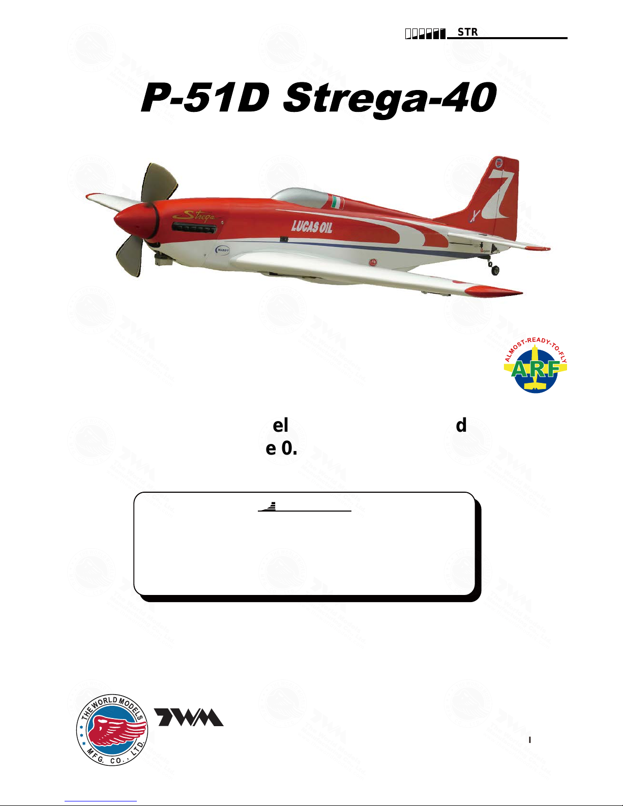
Warning! This model is not a toy.
It is designed for maximum performance. Please seek advice if one is not familiar with this kind
of engine powered precision model. Operating this model without prior preparation may cause
injuries. Remember, safety is the most important thing. Always keep this instruction manual at
hand for quick reference.
*Specifications are subject to change without notice.*
INSTRUCTION MANUAL
Wing Span
Wing Area
Flying Weight
Fuselage Length
56.5 in / 1435 mm
558 sq in / 36 sq dm
6.8 Ib / 3100 g
51 in / 1290 mm
Specifications
FACTORY PRE-FABRICATED
ALMOST-READY-TO-FLY(ARF)SERIES
MADE IN CHINA
The World Models
Manufacturing Co., Ltd.
www.theworldmodels.com
(
A341
)
Requires: 5-channel radio w/ 5 standard servos,
2-stroke 0.40-0.46 engine
4-stroke 0.70-0.81 engine
A341PO31811702
INDEX
BEFORE YOU BEGIN
BEFORE YOU BEGIN
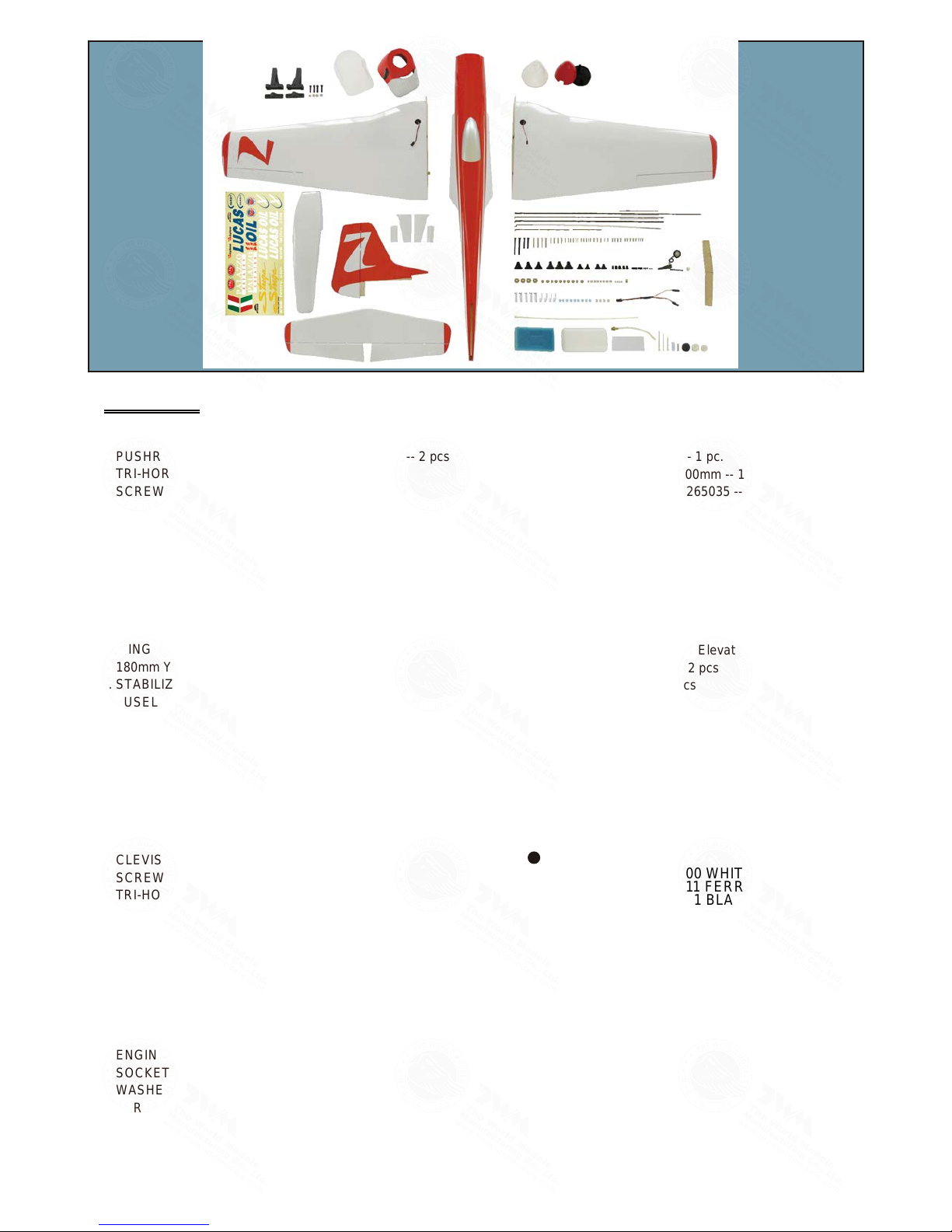
PARTS LIST
ASSEMBLY
SAFETY PRECAUTIONS
P.1
P.2
P.3-P.13
P.14
Check all parts. If you find any defective or missing parts contact your local dealer. Please
DRY FIT and check for defects for all parts that will require CA or Epoxy for final assembly.
Any parts you find to be defective after the gluing process may be difficult to remove for
warranty replacement. The manufacturer will replace any defective parts, but will not extend
to the parts that are good before gluing to defective parts during assembly. Warranty will
not cover any parts modified by customer.
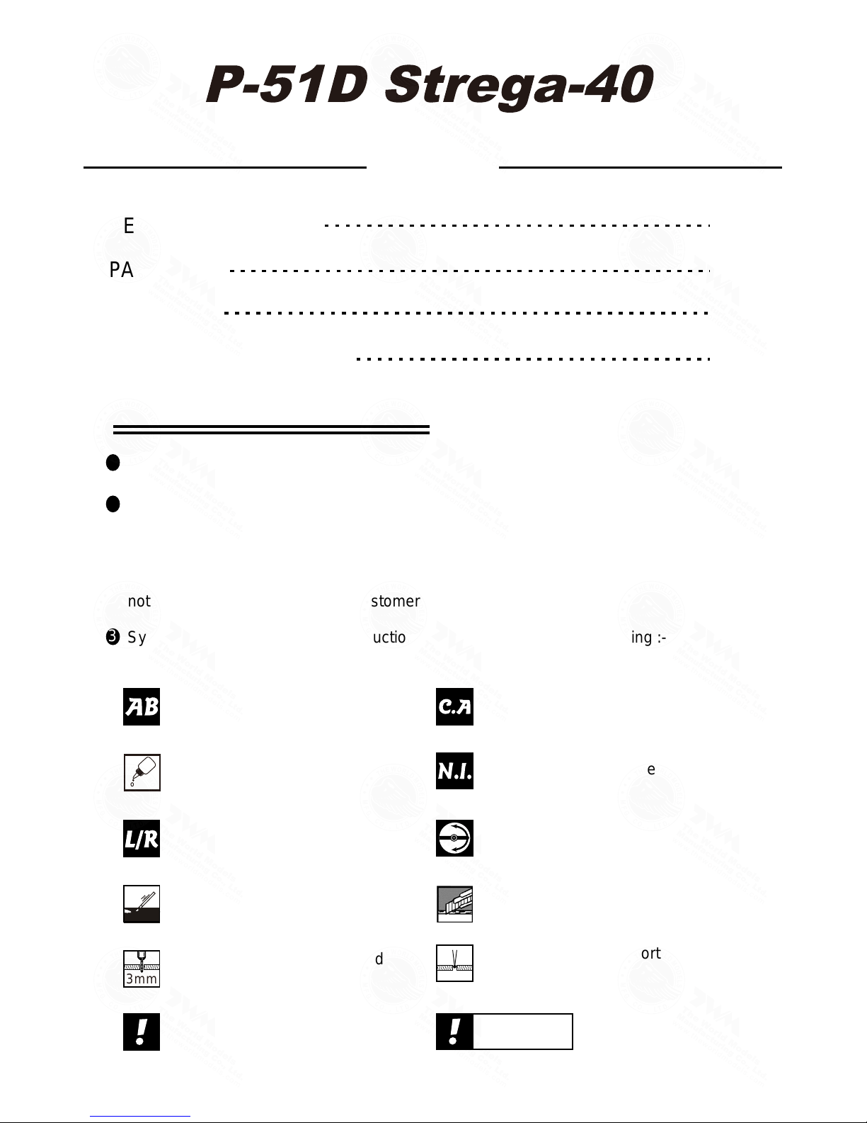
Symbols used throughout this instruction manual comprise of the following :-
Read through the manual before you begin, so you will have an overall idea of what to do.
1
2
3
P.1
Cut off shaded portion.
Ensure smooth non-binding
movement while assembling.
Apply instant glue
(C.A.glue, super glue.)
Assemble left and right
sides the same way.
Peel off shaded portion
covering film.
Pay close attention here!
Apply epoxy glue.
Must be purchased separately !
Drill holes with the specified
diameter (here: 3mm).
Pierce the shaded portion
covering film.
3mm
Do not overlook this symbol !
Warning!
Apply thread locker
A341PO31811702
P.2
Parts List
COVERING:--
TOUGHLON STL 100 WHITE
TOUGHLON STL 311 FERRARI RED
TOUGHLON STL 201 BLACK
TOUGHLON STL 250 BLUE
TOUGHLON STL 331 CUB YELLOW
10. FUEL TANK 450cc -- 1 set
CABLE TIE 1.5x5x400mm -- 1 pc.
DOUBLE-SIDE TAPE 40x100mm -- 1 pc.
11. SILICON GROMMETS PL1265035 -- 4 pcs
SPINNER Ø82mm PL2111082 -- 1 set
SCREW PWA2.6x12mm -- 4 pcs
COWLING --1 pc.
TRANSPARENT 3D TEMPLATE -- 1 pc.
12. LINKAGE CONNECTOR Ø2.1mm w/ set screw -- 1 set
13. STRAPER PL4112102 -- 2 pcs
FUEL TUBE D6x5mm -- 2 pcs
PUSHROD CONNECTOR PL4410010 -- 1 set
PUSHROD Ø1.8x75mm (For Elevator) -- 1 pc.
SPONGE 60x70x105mm -- 2 pcs
14. SCREW HM4x30mm -- 2 pcs
SCREW HM4x55mm -- 2 pcs
WASHER d4xD15mm -- 4 pcs
15. SCREW PM3x13mm -- 1 pc.
WASHER d3xD7mm -- 1 pc.
AIR SCOOPY -- 1 pc.
16. DECALS: A341 DEC -- 1 set
1. MAIN WING -- 1 pair
2. PUSHROD Ø1.8x95mm w/ Threads (For Aileron) -- 2 pcs
TRI-HORN PL4111221 -- 2 sets
SCREW PB2x18mm -- 4 pcs
SCREW PB2x14mm -- 2 pcs
SCREW PWA2.3x8mm -- 8 pcs
CLEVIS PL4112103 -- 2 pcs
FUEL TUBE D6x5mm -- 4 pcs
STRAPER PL4112102 -- 2 pcs
SERVO MOUNTING PANEL PL5310000 -- 1 pair
MAIN LANDING GEAR COVERS -- 1 pair
RETRACTABLE LANDING GEAR COVERS -- 1 set
WING JOINER 8x22.7x219mm -- 1 pc.
180mm Y-CORD KW0021800 -- 1 pc.
3. STABILIZER & ELEVATOR -- 1 set
FUSELAGE -- 1 pc.
4. VERTICAL FIN & RUDDER -- 1 set
5. PUSHROD Ø1.8x500mm w/ Threads (For Elevator) -- 2 pcs
SCREW PB2x14mm -- 4 pcs
SCREW PB2x12mm -- 2 pcs
CLEVIS PL4112103 -- 2 pcs
TRI-HORN PL4111221 -- 2 sets
FUEL TUBE D6x5mm -- 2 pcs
6. PUSHROD Ø1.8x630mm w/ Threads (For Rudder) -- 1 pc.
CLEVIS PL4112103 -- 1 pc.
SCREW PB2x12mm -- 3 pcs
TRI-HORN PL4111221 -- 1 set
FUEL TUBE D6x5mm -- 1 pc.
7. TAIL LANDING GEAR -- 1 set
TAIL WHEEL Ø25mm -- 1 pc.
COLLAR Ø2.1mm w/ Set Screw -- 1 set
SCREW PA3x14mm -- 2 pcs
SCREW PM2x10mm -- 1 pc.
ALUMINIUM PLATE 0.3mm -- 1 pc.
M2 NUT -- 1 pc.
8. ENGINE MOUNT PL5111050 -- 1 set
SOCKET HEAD SCREW M4x25mm -- 4 pcs
WASHER d4xD9mm -- 4 pcs
9. THROTTLE PUSHWIRE Ø1.2x500mm -- 1 pc.
PLASTIC TUBE d2xD3x360mm -- 1 pc.
SCREW PM3.5x30mm -- 4 pcs
WASHER d3.5xD8mm -- 8 pcs
M3.5 NUT -- 8 pcs
A341PO31811702
P.3
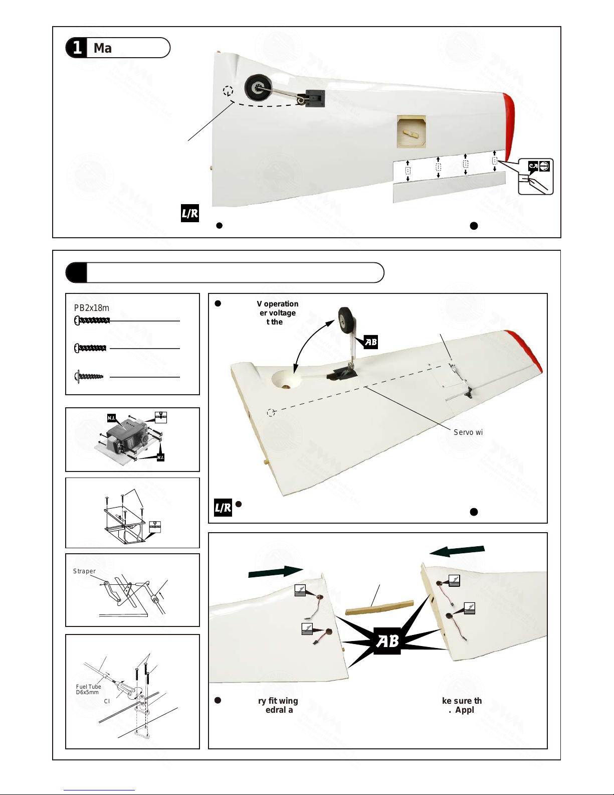
Main Wing
1
Aileron Pushrod & Retractable Landing Gear
2
PB2x18mm Screw
4
Ø1mm pilot holes for World Models horn are pre-drilled.
Please look for pin-hole marks at under side of control surfaces.
Straper
Fuel Tube
D6x5mm
PB2x18mm
PB2x14mm
Clevis
Tri-horn
M3x14mm
Pushrod
Ø1.8x95mm
Fuel Tube
D6x5mm
PB2x14mm Screw
2
PWA2.3x8mm n Screw
8
1.5mm
PWA2.3x8mm
1.5mm
Servo wire
Wing Joiner
Please dry fit wing joiner into left and right wing to make sure they fit with the
proper dihedral angle, mark the wing joiner if necessary. Apply epoxy glue to
both sides of all surfaces in contact. Use a stick to apply the glue to inner side
of wing joiner sleeve, and apply the glue to wing joiner before putting them
together. Wing joiner not glued properly will lead to wing failure and plane crash.
Apply instant type CA glue to both sides of each hinge.
4.8V - 6.0V operation
only, higher voltage
will burn out the
retract motor.
Electric retract wire
PWA2.3x8mm
Bottom View
Bottom View
A341PO31811702
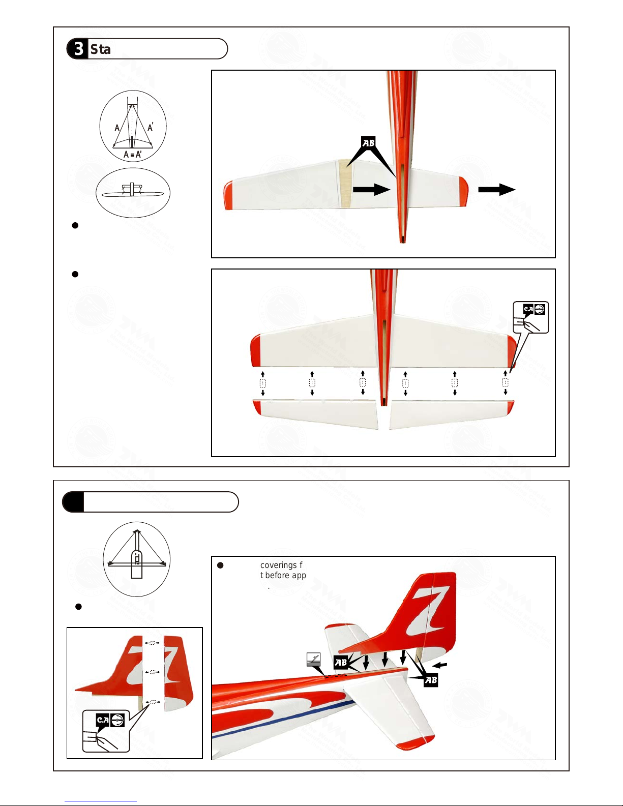
Stabilizer & Elevator
3
Vertical Fin & Rudder
4
P.4
Remove coverings for all surfaces
in contact before applying A/B
epoxy glue.
C C'
C=C'
Apply instant type CA glue to
both sides of each hinge.
Apply instant type CA glue to
both sides of each hinge.
Temporary install the main wing,
adjust leveling of the stabilizer
to make it as parallel to the main
wing as possible
(Stabilizer)
(Main Wi ng)
B B'
B=B'
A341PO31811702

PB2x14mm Screw
4
PB2x12mm Screw
2
PB2x12mm Screw
3
Elevator Pushrod
5
Rudder Pushrod
6
Tail Landing Gear
7
P.5
PB2x14mm
PB2x12mm
Clevis
Tri-horn
M3x14mm
Pushrod
Ø1.8x500mm
Fuel Tube
D6x5mm
PA3x14mm Screw
2
M2 Nut
1
PM2x10mm
Aluminium Plate
M2 Nut
Ø1mm pilot holes for World Models horn are pre-drilled. Please look for pin-hole marks at
under side of control surfaces.
PB2x12mm
Fuel Tube
D6x5mm
Pushrod
Ø1.8x630mm
Clevis
Tri-horn
M3x14mm
Ø1mm pilot holes for World Models horn are pre-drilled. Please look for pin-hole marks at
side of control surfaces.
2.1mm Collar
PA3x14mm
3mm set screw
1.5mm
PM2x10mm Screw
1
2.1mm Collar
1
Bottom View
Bottom View
Bottom View
A341PO31811702

P.6
Engine Mount
8
Engine Mount PL5111050
M4x25mm
d4xD9mm
M4x25mm Socket Head Screw
d4xD9mm Washer
4
4
Apply thread locker to screws
For short engines, add base brackets.
Blind nuts are off-centered
to keep the spinner at the
fuselage axis.
Engine
9
PM3.5x30mm Screw
d3.5xD8mm Washer
4
8
8
M3.5 Nut
Throttle Pushwire
Ø1.2x500mm
Plastic Tube
d2xD3x360mm
PM3.5x30mm
d3.5xD8 Washer
M3.5 Nut
Illustration is for inverted mounting.
You can mount the engine upright or
side ways simply by rotation the
engine mount. Thrust angles will not
be affected.
118 mm
4.65 in.
For short engines.
A341PO31811702

Cowling
11
P.7
First insert the grommet to the
cowling then apply screw.
d1.5xD6.5mm
Grommet
Cowling
Fuselage
PWA2.6x12mm
PWA2.6x12mm Screw
4
d1.5xD6.5mm Silicon Grommets
4
Silicon Grommets
PWA2.6x12mm
Spinner
Fuel Tank
10
Front
Cable Tie 1.5x5x400mmDouble-sided Tape 40x100mm
A341PO31811702

Servos Setting
13
P.8
Fuel Tube
D6x5mm
Straper
Sponge
60x70x105mm
Elevator Pushrod
Ø1.8x500mm
Rudder Pushrod
Ø1.8x630mm
Throttle Puswire
Ø1.2x500mm
Rudder Servo
Elevator Servo
Reciever
Battery
Throttle Servo
Install and arrange the servo as shown in the diagram.
Elevator Servo
Pushrod Connector
J1(Pushrod Ø1.8x75mm)
J1
J2
Servo Set
12
Throttle Pushwire
3x3mm Set Screw
Washer
2mm
Washer
2mm
M2 Nut
Throttle Servo
1.5mm
Please refer to the attached sheet for linkage connector installation.
3x3mm Set Screw
M2 Nut
Linkage Connector
1
1
1
2
2mm Washer
Plastic Tube
d2xD3x360mm
A341PO31811702

HM4x30mm Screw
d4xD15mm Washer
2
4
HM4x55mm Screw
2
Air Scoopy
15
P.9
Main wing
14
HM4x30mm
PM3x13mm
HM4x55mm
d4xD15 Washer
d3xD7 Washer
Air Scoopy
d4xD15 Washer
Completed
PM3x13mm Screw
d3xD7mm Washer
1
1
A341PO31811702

P.10
Wing Setting & Decals
16
A
B
C
A`
B`
C`
A=A`
B=B` C=C`
A341PO31811702

P.11
Control Throws
17
C.G.
18
128mm
C.G.
15mm
15mm
Elevator
28mm
28mm
Rudder
8mm
8mm
Ailerons
Adjust the control throws as shown in the diagram. These throws are good for general
flying. You can adjust according to your personal preference.
5.04 in.
http://www.theworldmodels.com/para/instruction/instructionManuals.php
The ideal C.G. position is 128mm (5.04 in.) behind the leading edge
measured at where the wing meets the fuselage. In order to obtain
the C.G. specified, add weight to the fuselage or move the battery
position. Check the C.G. before flying.
If you are converting this model to electric, please move the C.G.
forward 5% of current C.G. distance from leading edge to
compensate for weight of fuel.
If you are racing the Strega over 100 mph, move C.G. forward
by 1/2 inch.
A341PO31811702

P.12
Important Safety Precautions
First time flyer should never fly by himself / herself. Assistance from experienced flyer is
absolutely necessary.
Pre - flight adjustment must be done before flying, it is very dangerous to fly a badly
adjusted aircraft.
pre -
Make sure the air field is spacious, never fly the plane too close to people and never get
too close to a running propeller.
If you find wrinkles on the covering as a result of
weather changes, you can use hot iron
to remove the wrinkles. Please begin with lower temperature setting and gradually raise
the temperature until the wrinkles are gone. Too hot an iron may damage the covering.
Don,t use hot iron near the seams or edges, hot iron will melt the glue and shrink the covering at the
same time, causing the seams to pull away.
Check and re-tighten up all factory assembled screws, use thread locker if necessary.
i
s specially designed to be powered by
2-stroke 0.40-0.46
engine
performance. In fact, over powered
engine may
cause severe damage and injuries.
or
4-stroke 0.70-0.81
engine, using a more powerful engine does not mean better
Should you require to bend the landing gear wire, please dismantle the retract assembly from the wings
and use a vise to clamp the wire for bending. Bending the wire directly with the retract still in the wings
will damage the mounting block structure.
#
#
#
#
#
#
Warning!
A341PO31811702

LINKAGE CONNECTOR
HW7111050 & HW7111060
After fastening the round nut, make sure that
the linkage connector can rotate freely.
Drill 2mm hole at servo horn.
Insert linkage connector
into servo horn.
Make sure shoulder of
screw is cleared from
servo horn.
Add washer to reduce
play if necessary.
Shoulder
Tighten up the round nut
against the shoulder. Apply
CA or permanent thread
locker.
Product Registration Form (US Customers)
We would like to share with you any relevant information regarding your model, including
product news and free upgrade parts when applicable. Please fill in the following and
send to AirBorne Models, 4749-K,Bennett Drive, Livermore, CA 94551 USA.
1. Name:______________________________________________
2. Address:____________________________________________
3. Phone #:____________________ E-mail:__________________
4. Model:______________________________________________
Wing QC#__________ Fuselage QC# _______________________
(QC numbers are stamped on wing and fuselage)
5. Date of Purchase:_____________________________________
6. Store Name: _________________________________________
Please call AirBorne Models at 925 37 1 0922 for any assistance in filling this
form.Thank you very mu ch for purchasing our product.
A341PO31811702

This transparent 3D template
is used for position guidance
of the actual cutting of the
pre-painted cowling.
Usage of the transparent 3D template
Simply cut the transparent 3D template to fit your engine and
exhaust pipe, then slide onto the actual cowling and use as
template to mark the openings required for final cutting.
1 2
3 4
A341PO31811702

A341PO31811702
 Loading...