


Wing Span
Wing Area
Flying Weight
Fuselage Length
64 in / 1630 mm
657 sq in / 42.4 sq dm
5.1 lb / 2300 g
50 in / 1270 mm
Warning ! This model is not a toy.
It is designed for maximum performance. Please seek advice if one is not familiar with this kind
of engine powered precision model. Operating this model without prior preparation may cause
injuries. Remember, safety is the most important thing. Always keep this instruction manual
at hand for quick reference.
Requires :
4- channel radio w/ 4 standard servos
0.40-0.46 cu. in. displacement 2-stroke
* Specifi cations are sub ject to change wi thout noti ce. *
INSTRUCTION MANUAL
Specifications
FACTORY PRE-FABRICATED
ALMOST-READY-TO-FLY (ARF) SERIES
MADE IN CHINA
E
A
D
R
-
Y
T
-
T
S
O
O
-
F
M
L
L
Y
A
A234PO28901305
P. 1
P. 3 - 12
Check all parts. If you find any defective or missing parts contact your local dealer. Please DRY FIT
and check for defects for all parts that will require CA or Epoxy for final assembly. Any parts you
find to be defective after the gluing process may be difficult to remove for warranty replacement. The
manufacturer will replace any defective parts but will extend to the parts that are good before
, not
gluing to defective parts during assembly.
Warranty will not cover any parts modified by customer.
IND EX
BEFORE YOU BEGIN
PARTS LIST
ASSEMBLY
P. 1
P. 2
P. 12
BEFORE YOU BEGIN
Read through the manual before you begin, so you will have an overall idea of what to do.
Symbols used throughout this instruction manual comprise of the following : -
1
2
3
SAFETY PRECAUTIONS
3mm
Do not overlook this symbol!
Cut off shaded portion.
Peel off shaded portion
covering film.
Pay close attention here!
Pierce the shaded portion
covering film.
Must be purchased separately!
Drill holes with the specified
diameter (here: 3mm).
Ensure smooth non-binding
movement while assembling.
Apply instant glue
(C.A.glue, super glue.)
Assemble left and right
sides the same way.
Apply epoxy glue.
Apply thread locker
A234PO28901305
P.2
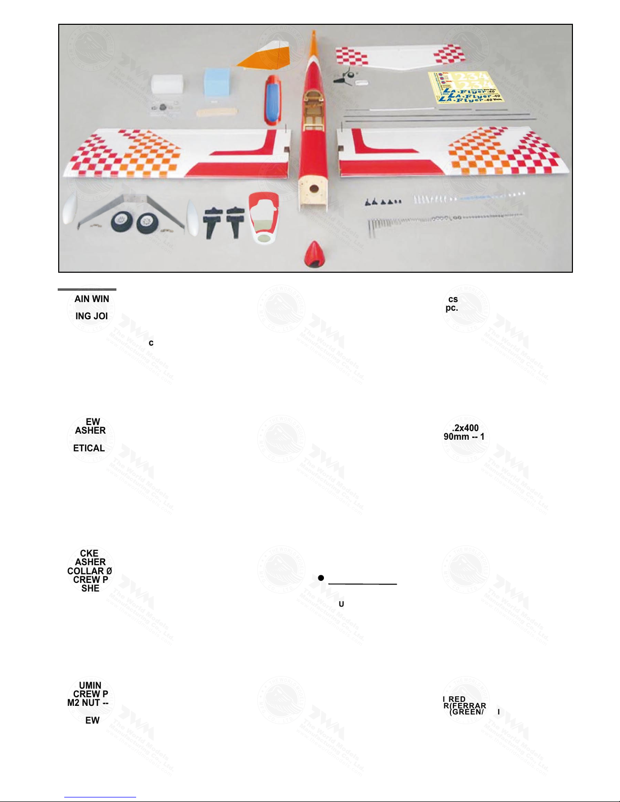
1. MAIN WING -- 1 pair
2. WING JOINER 8x25x201mm -- 1 pc.
3. PLYWOOD 3x10x20mm -- 2 pcs
RING Ø2.3mm -- 2 pcs
4. PUSHROD Ø1.8x100mm w/ Threads(For Aileron) -- 2 pcs
FUEL TUBE Ø6x5mm -- 4 pcs
STRAPER-- 2 pcs
CLEVIS-- 2 pcs
5. STABILZER & ELEVATOR -- 1 set
FUSELAGE -- 1 pc.
SCREW PM3x16mm -- 2 pcs
WASHER d3xD7mm -- 2 pcs
6. VETICAL FIN & RUDDER -- 1 set
7. ENGINE MOUNT PL511030 -- 1 set
SOCKET HEAD SCREW M3x20mm -- 4 pcs
WASHER d3xD7mm -- 4 pcs
8. FUEL TANK 320cc -- 1 set
CABLE TIE 1.5x5x400mm -- 1 pc
DOUBLE-SIDED TAPE 40x100mm -- 1 pc.
BATTERY COVER -- 1 pc.
9. MAIN LANDING GEAR -- 1 set
SOCKET HEAD SCREW M3x14mm -- 3 pcs
WASHER d3.2xD12mm -- 3 pcs
COLLAR Ø4.1mm w/ set screw -- 4 sets
SCREW PM4x38mm -- 2 pcs
WASHER d4xD9mm -- 4 pcs
M4 NUT -- 2 pcs
QUICK RELEASE NYLON RIVET PL1208042 -- 4 pcs
MAIN WHEEL Ø62mm -- 2 pcs
ALUMINUM PLATE 1mm -- 2 pcs
WHEEL PANTS -- 1 pair
10. TAIL LANDING GEAR -- 1 set
SCREW PA3x12mm -- 2 pcs
COLLAR Ø2.1mm w/ set screw -- 1 set
TAIL WHEEL Ø25mm -- 1 pc.
ALUMINUM PLATE 0.3mm -- 1 pc.
SCREW PM2x10mm -- 1 pc.
M2 NUT -- 1 pc.
11. SCREW PB2x12mm -- 2 pcs
FUEL TUBE Ø6x5mm -- 1 pc.
CLEVIS -- 1 pc.
HORN -- 1 set
PUSHROD Ø1.8x720mm w/ Threads(For Elevator) -- 1 pc.
FUEL TUBE Ø6x5mm -- 1 pc.
CLEVIS -- 1 pc.
HORN -- 1 set
PUSHROD Ø1.8x720mm w/ Threads(For Rudder) -- 1 pc.
13. SOCKET HEAD SCREW M3x25mm -- 4 pcs
WASHER d3xD7mm -- 8 pcs
M3 NUT -- 8 pcs
14. LINKAGE CONNECTOR Ø2.1mm -- 1 set
15. SPONGE 60x70x80mm -- 1 pc.
FUEL TUBE Ø6x5mm -- 2 pcs
STRAPER -- 2 pcs
THROTTLE PUSH WIRE Ø1.2x400mm -- 1 pc.
w/ Plastic Tube d2xD3x190mm -- 1 pc.
16. CANOPY -- 1 pc.
PVC PLATE 1x14.3x78mm (Wing Protection) -- 1 pc.
SCREW HM4x35mm -- 2 pcs
WASHER d4xD12mm -- 2 pcs
17. COWLING -- 1 pc.
TRANSPARENT 3D TEMPLATE -- 1 pc.
SPINNER Ø57mm -- 1 set
SCREW PWA2.6x12mm -- 4 pcs
SILICON GROMMET d1.5xD6.5mm -- 4 pcs
18. DECALS: A234DEC – 1 set
12. SCREW PB2x12mm -- 2 pcs
Parts List
COVER ING:--
BLAC K CO LOR SCH EM E:
TOUGHLON S TL 1 00 W HITE
TOUGHLON S TL 2 01 B LACK
TOUGHLON S TL 3 11 FE RRARI R ED
TOUGHLON S TL 4 02 C HECKE R( BLACK/W HITE)
TOUGHLON S TL 4 12 C HECKE R( FERRARI /WHITE)
ORAN GE C OLOR SCHE ME:
TOUGHLON S TL 1 00 W HITE
TOUGHLON S TL 3 11 FE RRARI R ED
TOUGHLON S TL 3 20 O RANGE
TOUGHLON S TL 4 12 C HECKE R( FERRARI /WHITE)
TOUGHLON S TL 4 22 C HECKE R( ORANGE/ WHITE)
GREE N CO LOR SCHEM E:
TOUGHLON S TL 1 00 W HITE
TOUGHLON S TL 2 40 G REEN
TOUGHLON S TL 3 11 FE RRARI R ED
TOUGHLON S TL 4 12 C HECKE R( FERRARI /WHITE)
TOUGHLON S TL 4 42 C HECKE R( GREEN/W HITE)
BLUE C OL OR SCHE ME :
TOUGHLON S TL 1 00 W HITE
TOUGHLON S TL 3 11 FE RRARI R ED
TOUGHLON S TL 2 50 B LUE
TOUGHLON S TL 4 12 C HECKE R( FERRARI /WHITE)
TOUGHLON S TL 4 52 C HECKE R( BLUE/WH ITE)
A234PO28901305
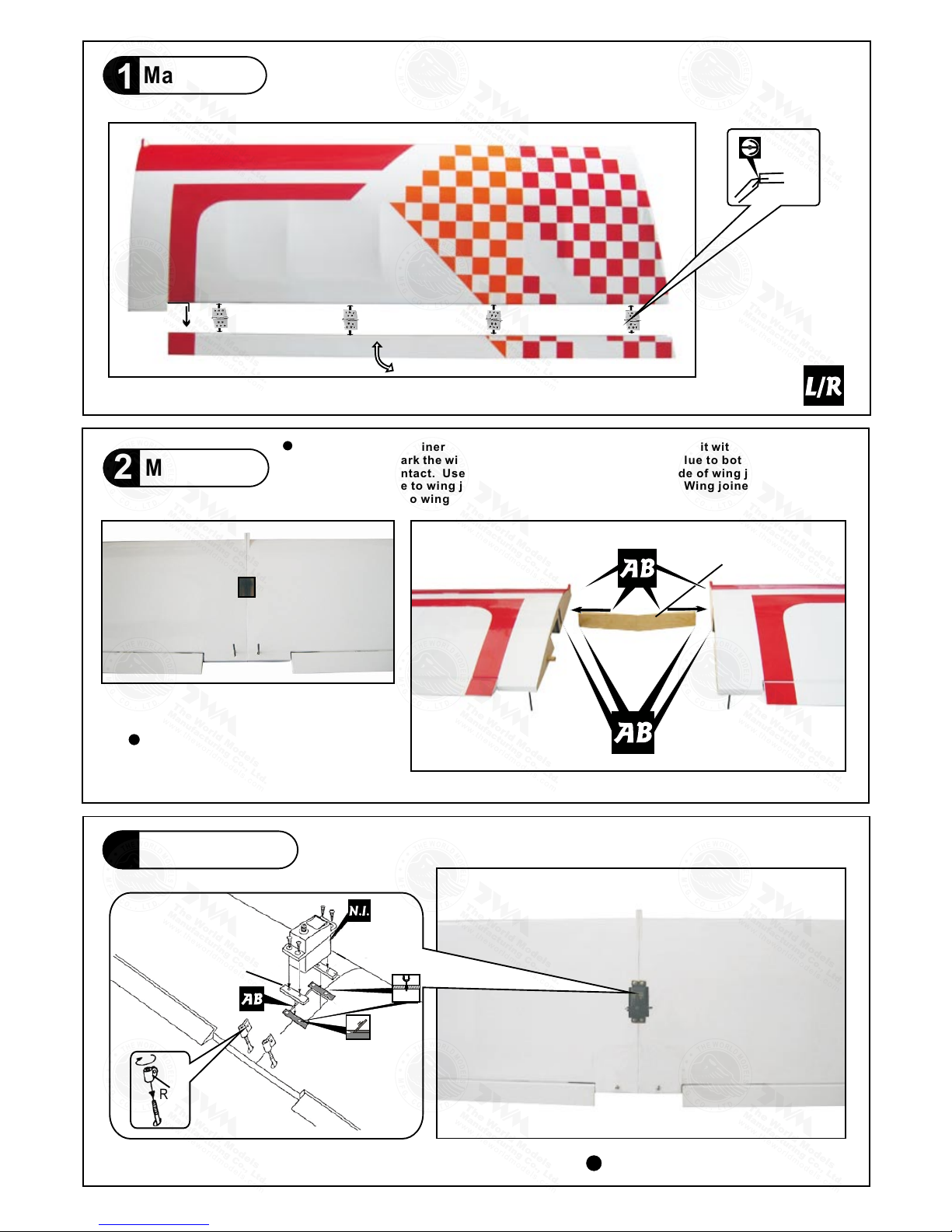
Main Wing
1
P.3
Make sure to glue securely.
If not properly glued, a failure
in fight may occur.
Main Wing
2
completed
Aileron Servo
3
Wing Jo iner
8x25x 201mm
1mm
Ring
Plywood
1.5mm
3x10x20m m
Bottom View
Pre-glued
1.5 mm
Plea se d ry fit wing j oiner int o le ft and ri gh t wing to mak e su re they f it w ith the p ro per
dihe dr al angle, m ark the win g jo iner if n ec essary. App ly epoxy g lu e to b ot h s id es of
all s ur faces i n con tact. Use a stic k t o a pply the gl ue to inner side of w in g joi ne r sle ev e,
and a pp ly the glu e to w in g joi ne r bef or e put ting the m t ogeth er. Wi ng joiner n ot glued
prop er ly will l ead t o w ing f ai lure a nd p lane cra sh .
A234PO28901305
P.4
Stabilizer & Elevator
5
2
2
PM3x16mm Screw
d3xD7mm Washer
PM3x16m m
Was her
d3xD7mm
Completed
Temporary install the main wing, adjust
leveling of the stabilizer to make it as
parallel to the main wing as possible.
(Sta biliz er )
(Mai n Wing)
B
B'
B=B'
A=A
A
A
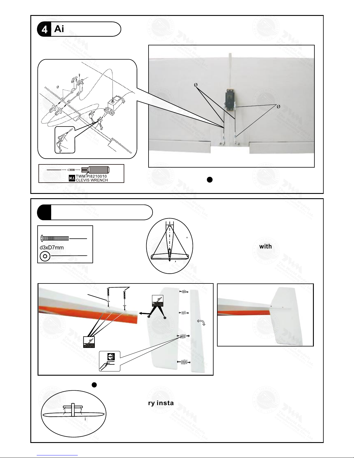
Aileron Servo
4
Fuel Tube
6 x 5 mm
Pushrod 1.8x100 mm
Straper
Fuel Tube
6x5mm
Ring
Clev is
Bottom View
Use thread locker when tightening
screw. Don't use excessive force
as you are dealing with balsa.
Bottom View
Pre -glue d
A234PO28901305

P.5
Fuel Tank
8
Engin e Mount PL5111-030
M3 x 20mm
Blind nuts are off-ce ntered to k eep
the spi nner at the fuse lage axis .
Apply t hread locker t o screws.
Engine Mount
7
Washer
d3xD7 mm
4
4
d3xD7mm Washer
Vertical Fin / Rudder
6
P r e - g l u e d
C=
C
C'
C'
Compl eted
M3x20mm
Socket Head Screw
Fuel Tank 32 0c c
1 2 3
Cabl e Tie
1.5x 5x 400mm
Doub le -side d Tape
40x1 00 mm
Batt er y Cover
Remov e coverings for all surfa ces in contact before app lying A/B epoxy gl ue.
A234PO28901305

Completed
P.6
Tail Landing Gear
10
BottomView
PA3x1 2mm Screw
2.1mm Collar
2
1
PM2x10mm Screw
M 2
N u t
1
1
PA3x12mm
Completed
PA3x12mm
2.1mm Collar
M3 Set Screw
PM2x1 0mm
Alumi num Plate
M2 Nut
2mm
2mm
Bottom View
PM4x38mm
Screw
M4 Nut
d3.2xD12m m Washer
Ø
marks at under side of fuselage.
1mm pilot holes are pre-drilled. Please look for pin-hole
Main Landing Gear
9
4. 1 mm
Coll a r
4
2
3
Plate 1mm
M3 x14 mm
Was he r
d3.2 x D1 2mm
M3x14mm Socket Head Screw
3
Wheel Ø62
Was he r d4 xD 9m m
3mm
Set Screw
Ø4.1 Collar
M4 Nut
PM4x38mm
3mm
Set Screw
KA2.3x8mm
d2xD8mm
Quick Release Nylon Rivet
2
d4xD9m m Washer
4
Quick Release Nylon Rivet
4
KA2.3x8mm Screw
4
A234PO28901305

Pushrod
Ø1.8x720mm
1
80m
m
6
4
m
m
P.7
Elevator Pushrod
11
2
PB2 x 12mm Screw
1mm pilot holes for World Models tri-horn are pre-drilled.
Ø
Please look for pin-hole marks at under side of control surfaces.
Rudder Pushrod
12
2
PB2 x 12mm Screw
1mm pilot holes for World Models tri-horn are pre-drilled.
Ø
Please look for pin-hole marks at under side of control surfaces.
Pushrod
Ø1.8x720mm
1
5
m
m
1
0
0
m
m
Bottom View
Horn
Fuel Tube
6x5mm
Ø
Clevis
PB2x12mm
Pushrod
Ø1.8x720mm
Pushrod
Ø1.8x720mm
PB2x12m m
Clev is
Fuel Tu be
Ø6x5m m
Horn
A234PO28901305

P.8
3x3mm
Set Screw
2mm
Nut
Linkage Connector
1
1
1
2
2mm
Washer
LINKAGE CONNECTOR
Servo Set
14
Engine
13
M3x25mm
Socket Head Screw
d3xD7mm
Washer
M3
Nut
4
8
8
Installed Engine Position
M3x25mm
Throttle Pushwire
w/plastic tube
3mm Was he r
M3 Nut
3mm
Was he r
3.2mm
100mm
3.93 in
3.2 mm
T
h
r
o
t
t
l
e p
u
s
hw
i
re
3mm
Include d with the rad io Se t.
Throttl e Servo.
2mm
M2 Nut
Pleas e refer to attached sheet f or linkage connector in stallat ion.
2mm
2mm
A234PO28901305

16
Main Wing & Canopy
2
2
HM4x35mm Screw
d4xD12mm Washer
Washer
d4xD12mm
HM4x35mm
Wing Protection
1x14.3x78mm
Install and arrange t h e servo as s h o w n i n the diagram.
Servos
15
Eleva tor Pushrod
Spong e
Throt tle Pushwire
Ø1.2x4 00mm
Rudde r Pushrod
Fuel Tub e
Ø6x5mm
18
17
Cowling
4
4
PWA2.6x12mm Screw
d1.5xD6.5mm Silicon Grommet
Spinner Ø57mm
1mm
P.9
Front
First insert the grommet to the cowling then apply screw.
1mm
Please refer to the attached sheet for usage of the
transparent 3D template.
Eleva tor Servo
Rudde r Servo
Throt tle Servo
Batte ry
Switc h Harness
Recei ver
PWA 2. 6x 12 mm
Silicon Grommet
d1.5xD6.5mm
Cowling
Fuselage
Char ge R ecept ac les
KP00 41 300
strap er
A234PO28901305

P.10
Adjust the wing and fuselage configuration as shown
in the diagrams.
C = C'
A = A'
B = B'
Wing Setting
18
C'C
A
B B'
A'
A234PO28901305

#First time flyer should never fly by himself / herself. Assis tanc e from e xper ienc ed fly er is
absolutely necessary.
#Pre-flight adjustment must be done before flying, it is very dan gero us to fl y a badl y
pre-adjusted aircraft.
# is spec iall y desi gned t o be pow ered b y 2-stroke 0.40~0.46
engine, using a more powerful engine does not mean better performance. In fac t, ove r
powered engine may cause severe damage and injuries.
#Make sure the air field is spacious, never fly the plane too close to people and nev er get
too close to a running propeller.
#If you find wrinkles on the covering as a result of weather changes, you can u se hot i ron
to remove the wrinkles. Please begin with lower temperature setting a nd gra dual ly rai se
the temperature until the wrinkles are gone. Too hot an iron may damage the covering.
Don't use hot iron near the seams or edges, hot iron will melt the glue and shrink
the covering at the same time, causing the seams to pull away.
#Check and re-tighten up all factory assembled screws, use thread locker if
necessary.
Control Throws
19
Elevator
Rudder
Aileron
Important Safety Precautions
C.G.
20
C
.
G
.
8
1
m
m
3
.
1
9
i
n
6 mm
6 mm
Adjust the control throws as shown in
the diagram. These throws are good for
general flying. You can adjust according
to your personal preference.
The ideal C.G. position is 81mm (3.19 in) behind the leading edge
measured at where the wing meets the fuselage. In order to obtain
the C.G. specified, add weight to the fuselage or move the battery
position. Check the C.G. before flying.
If you are converting this model to electric, please move the C.G.
forward 10% of current C.G. distance from leading edge to
compensate for weight of fuel.
15 mm
15 mm
20 mm
20 mm
Warning!
P.11
http :/ /www.t he worldmo de ls.co m/ para/ in struc ti on/inst ru ction Ma nuals .p hp
A234PO28901305

LINKAGE CONNECTOR
HW7111050 & HW7111060
Drill 2mm hole at servo horn.
Insert linkage connector
into servo horn.
Make sure shoulder of
screw is cleared from
servo horn.
Add washer to reduce
play if necessary.
Sh oul de r
Tighten up the round nut
against the shoulder. Apply
CA or permanent thread
locker.
After fastening the round nut, make sure that
the linkage connector can rotate freely.
Product Registration Form (US Customers)
We would like to share with you any relevant information regarding your model, including
product news and free upgrade parts when applicable. Please fill in the following and send to
1.Name:
2.Address:
3.Phone #: e-mail:
4.Model:
Wing QC# Fuselage QC#
(QC numbers are stamped on wing and fuselage)
5.Date of Purchase:
6.Store Name:
Please call AirBorne Models at 925 371 0922 for any assistance in filling this form.
Thank you very much for purchasing our product.
Air orne Models, 4749-K,Bennett Drive, Livermore, CA 94551 USAB .
A234PO28901305

1
2
3
4
Usage of the transparent 3D template
This transparent 3D template
is used for position guidance
of the actual cutting of the
pre-painted cowling.
Simply cut the transparent 3D template to fit your engine and
exhaust pipe, then slide onto the actual cowling and use as
template to mark the openings required for final cutting.
P. 1 2
A234PO28901305

Optional Parts
180mm Extension
KW0011800 180mm 1 set
Code No. Size
Package
Fuel Filler
PL8110030 15 x 22 x 49mm 1 x 1 pc
Code No. Size
Package
Charge Receptacles
KP0041300
Code No. Size
Package
Field Stand
MS9111450 600 x 240 x 350mm 1 pc
Code No. Size
Package
180mm Y-Cord
KW0021800 180mm 1 pc
Code No. Size
Package
Clevis Wrench
PL8210010 1 set
Code No. Size
Package
Small Clevis Large Clevis
Special tool for clevis installation.
Suitable for standard and small
(EP) clevis.
Standard Servo
Code No SV4031
0.14 sec / 60° @6.0V
Torque : 3.2kg.cm / 44.8 oz - in @4.8V
4.1kg.cm / 57.4 oz - in @6.0V
Size : 40.6 x 20 x 37mm /
1.60 x 0.79 x 1.46 in
Weight : 39.4 g / 1.39 oz
Speed : 0.17 sec / 60° @4.8V
A234PO28901305

The World Models
Manufacturing Co., LTD.
www.theworldmodels. com
A234PO28901305
 Loading...