

Wing Span
Wing Area
Flying Weight
Fuselage Length
63.0 in / 1600 mm
688 sq in / 44 sq dm
6.8 lbs / 3100 g
59.0 in / 1500 mm
Warning ! This model is not a toy.
It is designed for maximum performance. Please seek advice if one is not familiar with this kind
of engine powered precision model. Operating this model without prior preparation may cause
injuries. Remember, safety is the most important thing. Always keep this instruction manual at
hand for quick reference.
* Speci ficatio ns are subj ect to chan ge withou t notice.*
Specifications
INSTRUCTION MANUAL
E
A
D
R
-
Y
T
-
T
S
O
O
-
F
M
L
L
Y
A
INTRUDER 90RINTRUDER 90R
FACTORY PRE-FABRICATED
ALMOST-READY-TO-FLY (ARF) SERIES
MADE IN CHINA
Required :
0.91 cu.in. displacement 4-stroke
4-channel radio w/ 5 standard servos
0.60-0.75 cu.in. displacement 2-stroke
A050RPO28881306
INTRUDER 90RINTRUDER 90R
Apply thread locker
Apply epoxy glue.
Pierce the shaded portion
covering film.
Appl
(C.A.glue, super glue.)
y instant glue
Ensur
movement while assembling.
e smooth non-binding
Do not overlook this symbol !
P. 3 -11
Check all parts. If you find any defective or missing parts contact your local dealer. Please DRY FIT
and check for defects for all parts that will require CA or Epoxy for final assembly. Any parts you
find to be defective after the gluing process may be difficult to remove for warranty replacement. The
manufacturer will replace any defective parts, but will
not
extend to the parts that are good before
gluing to defective parts during assembly. Warranty will not cover any parts modified by customer.
INDE X
BEFORE YOU BEGIN
PARTS LIST
ASSEMBLY
SAFETY PRECAUTIONS
P. 1
P. 2
P.11
BEFORE YOU BEGIN
Read through the manual before you begin, so you will have an overall idea of what to do.
Symbols used throughout this instruction manual comprise of the following : -
1
2
3
Assembl
sides the same way.
e left and right
Pee
covering film.
l off shaded portion
Drill holes with the specified
diameter (here:3mm).
Pay close attention here!
Cut off shaded portion.
Must be purchased separately !
Warning!
3mm
P.1
A050RPO28881306
Parts List
P.2
COVE RIN G:
TOUGHLON
STL 100 WHITE
TOUGHLON
STL 201 BLACK
TOUGHLON
STL 320 ORANGE
1. MAIN WING -- 1 pair
2. SCREW PB2x16mm -- 2 pcs
SCREW PB2x18mm -- 4 pcs
SCREW PWA2x8mm -- 8 pcs
FUEL TUBE Ø6x5mm -- 4 pcs
STRAPER PL4112102-- 2 pcs
CLEVIS PL4112103 -- 2 pcs
TRI-HORN M3x14mm PL4111185 -- 2 sets
PUSHROD Ø1.8x115mm w/ Threads (For Aileron) -- 2 pcs
SERVO MOUNTING PANEL PL5310000 -- 1 pair
3. WING TUBE Ø25.4x234mm -- 1 pc.
4. MAIN LANDING GEAR --1 set
SCREW PA3x12mm -- 8 pcs
WHEEL Ø52mm PL3111520 -- 2 pcs
COLLAR Ø4.1mm w/ set screw -- 4 sets
PLATE 12x
20mm (For Main Landing Gear) PL4114020 -- 4 pcs
5. FUSELAGE -- 1 pc .
STABILIZER & ELEVATOR -- 1 set
SCREW PWA3x12mm -- 2 pcs
STABILIZER TUBE D9.5x296mm -- 1 pc.
WIRE Ø3x97mm -- 1 pc.
6. VERTICAL FIN & RUDDER -- 1 set
7. ENGINE MOUNT (PL5111070) -- 1 set
SOCKET HEAD SCREW M4x25mm -- 4 pcs
WASHER d4xD12mm -- 4 pcs
8. FRONT LANDING GEAR -- 1 set
COLLAR Ø4.1mm w/ set screw -- 4 sets
WHEEL Ø52mm PL3111520 -- 1 pc.
STEERING ARM Ø4.1mm PL4112401 -- 1 set
9. FUEL TANK 320cc PL1
111320 -- 1 set
BALSA 10x10x89mm(For Fuel Tank Position Fixing) -- 1 pc.
10. SOCKET HEAD SCREW M4x30mm -- 4 pcs
WASHER d4xD9mm -- 8 pcs
M4 NUT -- 8 pcs
11. SCREW PB2x22mm -- 6 pcs
CLEVIS PL4112103 -- 2 pcs
FUEL TUBE Ø6x5mm -- 2 pcs
TRI-HORN M3x14mm (L) PL4111185 -- 2 sets
PUSHROD Ø1.8x760mm w/ Threads (For Elevator) -- 2 pcs
12. SCREW PB2x16mm -- 3 pcs
FUEL TUBE Ø6x5mm -- 1 pc.
CLEVIS PL4112103 -- 1 pc.
TRI-HORN M3x14mm (L) PL4111185 -- 1 set
PUSHROD Ø1.8x870mm w/ Thr
eads (For Rudder) -- 1 pc.
13. LINKAGE CONNECTOR Ø2.1mm HW7111060 -- 2 sets
14. STRAPER PL4112102 -- 2 pcs
FUEL TUBE Ø6x5mm -- 2 pcs
SPONGE 60x70x90mm (For Radio Equipment) -- 1 pc.
FRONT WHEEL PUSHROD Ø1.4x375mm -- 1 pc.
PLASTIC TUBE d2.5xD4x330mm -- 1 pc.
THROTTLE PUSHWIRE Ø1.2x425mm -- 1 pc.
PLASTIC TUBE d2xD3x330mm -- 1 pc.
PUSHROD Ø1.8x80mm (For Elevator) -- 1 pc.
PUSHROD CONNECTOR 4x9x20mm PL4410010 -- 1 set
15. SOCKET HEAD SCREW M4x30mm -- 2 pcs
WASHER d4
xD15mm -- 2 pcs
SCREW PWM3x13mm -- 1 pc.
PLYWOOD 2x24x68mm (Wing Protection) -- 1 pc.
BELLY PAN -- 1 pc.
16. COWLING -- 1 pc.
TRANSPARENT 3D TEMPLATE --1 pc.
SCREW PWA2.6x12mm -- 4 pcs
SILICON GROMMET d1.5xD6.5mm -- 4 pcs
SPINNER Ø70 PL2111070 -- 1 set
17. CANOPY -- 1 pc.
SCREW PWA2.3x8mm -- 3 pcs
SILICON GROMMET d1.5xD6.5mm -- 3 pcs
18. DECALS A050RDEC -- 1 set
A050RPO28881306
P.3
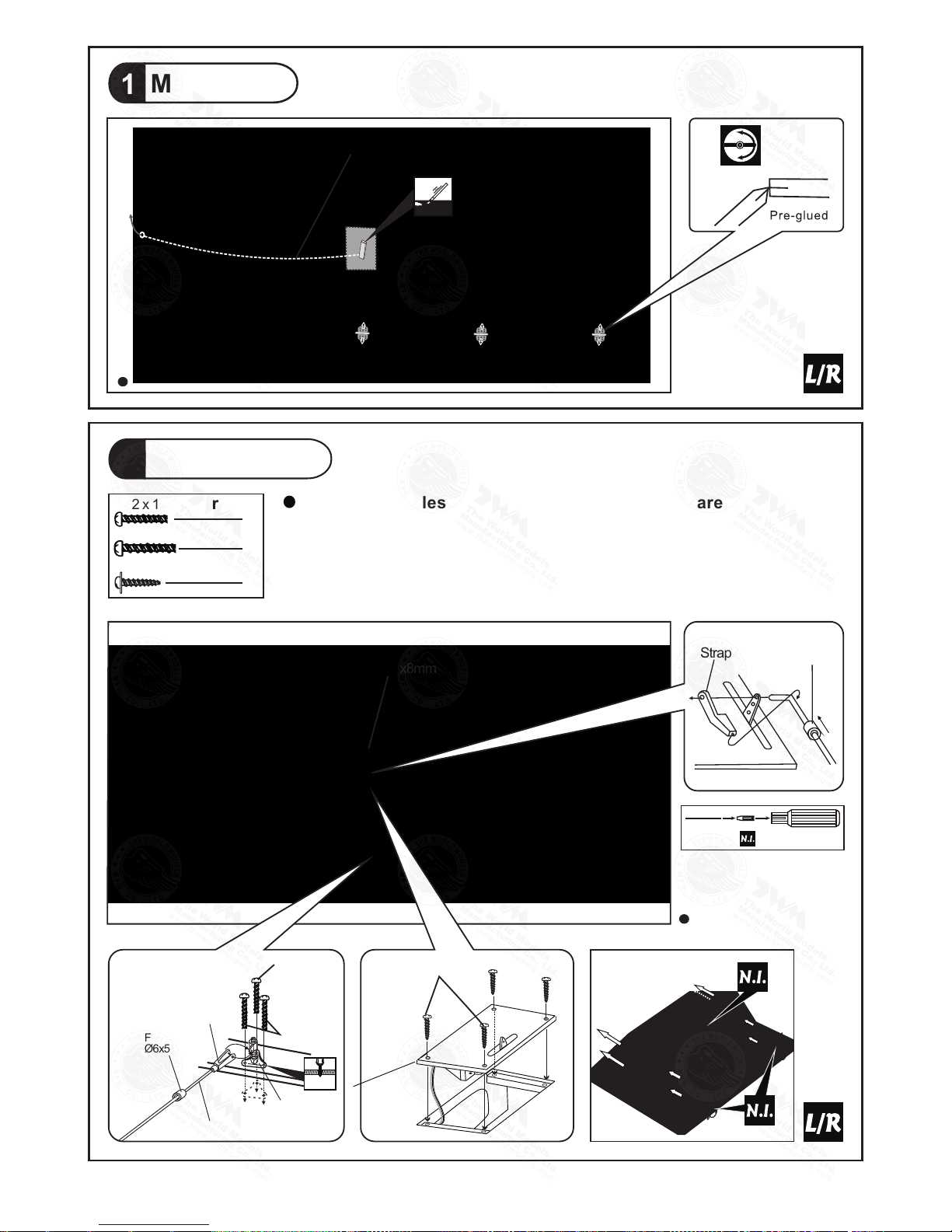
1
Main Wing
Aile ron S erv o Lead
Aileron Servo
2
Botto m View
2
PB2 x 16mm Screw
4
PB2 x 18mm Screw
8
PWA2 x 8mm Screw
Fuel Tube
Ø6x5mm
PB2x16mm
Tri-horn
M3x14mm
Clevis
Pushrod
Ø1.8x115mm
PB2x18mm
Fuel Tube
Ø6x5mm
Straper
PWA2x8mm
Botto m View
PWA2x8mm
Ø1mm pilot holes for The World Models tri-horn are pre-drilled.
Please look for pin-hole marks at under side of control surfaces.
2mm
TWM PL 82100 10
CLE VIS WREN CH
A050RPO28881306
P.4
3
Main Wing
Tube
Ø25.4x234mm
Wing
Botto m View
4
Main Landing Gear
PA3x12mm Screw
8
4
4
4.1mm
Wheel Collar
3mm Set Screw
Completed
One side only for
detachable wing.
Botto m View
3mm Set Screw
Wheel 52mmØ
Botto m View
Plate
PA3x12mm
1mm
A050RPO28881306

D9.5x296mm
1
2
5
m
m
65mm
PWA 3 x 12mm
P.5
Bottom View
6
Vertical Fin & Rudder
Completed
B=B'
B
B
5
Stabilizer & Elevator
PWA 3 x 12mm Screw
2
Botto m View
Ø3x97mm
Botto m View
PWA3 x 12mm
M3 x 6mm Set Screw
M3 x 6mm Set Screw
A
A’
A=A’
Botto m View
2mm
2mm
Botto m View
Botto m View
M3 x 6mm Set Screw
M3 x 6mm Set Screw
Top View
A050RPO28881306

P.6
Fuel Tank
9
Inst al l Ba lsa 10x10 x8 9m m
(For Fue l Tan k Po si tion Fixi ng )
Fuel Tank
320c c
Botto m View
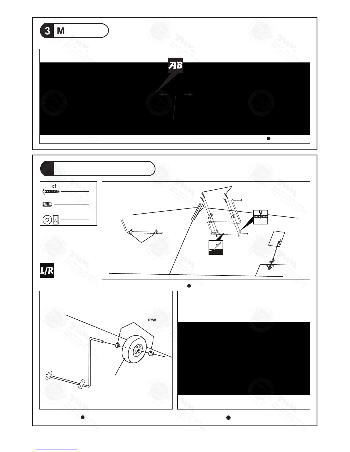
Front View
Wheel 52mmØ
3mm Set Screw
Botto m View
8
Front Landing Gear
4
4
3mm Set Screw
4.1mm Wheel Collar
Engine Mount
7
4
4
d4 x D12mm
Washer
Engine Mount
PL5111070
M4x mm
SOCKET HEAD SCREW
25
M4x25mm Socket Head Screw
d4 x D12mm Washer
Fuel Tank
320cc
UP
Completed
Steering Arm
A050RPO28881306

P.7
11
Elevator Pushrod
6
PB2 x 22mm Screw
42m
m
17
0
m
m
Botto m View
Fuel Tube
Ø6x5mm
PB2x22mm
Tri-horn
M3x14mm
Clevis
Pushrod
Ø1.8x760mm
Elevator Pushrod
Ø1.8x760mm
Ø
Please look for pin-hole marks at under side of control surfaces.
1mm pilot holes for The World Models tri-horn are pre-drilled.
Engine
10
8
8
132mm
5.2 in
Installed Engine Position
Botto m View
d4 x D9mm Washer
M4 Nut
M4 Nut
d4 x D9mm
Washer
M4x30mm Socket Head Screw
4
M4x30 mm
4mm
2mm
TWM P L8 21 0010
CLE VIS WRE NC H
A050RPO28881306

P.8
Servo Set
13
3 x 3mm Set Screw
Linka ge Stopper
2mm
Nut
2mm Washer
2
2
2
4
3
PB2 x 16mm Screw
3
4m
m
1
7
0
m
m
Botto m View
Fuel Tube
Ø6x5mm
PB2x16mm
Tri-horn
M3x14mm
Clevis
Pushrod
Ø1.8x870mm
Rudder Pushrod
Ø1.8x870mm
12
Rudder Pushrod
Ø
Please look for pin-hole marks at under side of control surfaces.
1mm pilot holes for The World Models tri-horn are pre-drilled.
14
Radio Equipment
Install and arrange the servo as shown
in the diagram.
Front
Sponge
60x70x90mm
Throttle Pushwire
Ø1.2x425mm
Elevator Servo
Elevator Pushrod
Rudder Pushrod
Rudder Servo
Front Wheel Pushrod
Ø1.4x375mm
Botto m View
d2xD3x330
Plastic Tube
mm
d2.5xD4x330
Plastic Tube
mm
KM 2x 8mm
M2 Nu t
Ele vator P ushro d
Ø1.8 x80mm
Battery
Receiver
Throttle Servo
Switch Harness
Elevator Servo
Push ro d Conne ct or
J1( P us hr od Ø1.8 x8 0m m)
J2( P us hr od Ø1. 8x 76 0mm)
J1
J2
2mm
Pleas e refer to th e attache d sheet for l inkage co nnector i nstalla tion.
Throttle Pushwir e
3x3mm Set Screw
Throttle Serv o.
2mm
2mm
Washer
M2 Nut
2mm
Washer
TWM PL8 21 00 10
CLEVIS WRE NC H
Charg e Recepta cles
KP004 1300
A050RPO28881306

P.9
17
Canopy
Cowling
16
3
3
d1.5 x D6.5 mm Silicon Grommet
PWA2.3 x 8mm Screw
4
4
d1.5 x D6.5 mm Silicon Grommet
PWA2.6 x 12mm Screw
Spinner
Ø70mm
PWA2.3 x 8mm
d1.5 x D6.5 mm Silicon Grommet
PWA2.6 x 12mm
d1.5 x D6.5 mm Silicon Grommet
Main Wing
15
Bottom View
Complet ed
d4xD15mm
M4x30mm
Wing Protection
2x24x68mm
2
d4 x D15mm Washer
2
PWM3 x 13mm Screw
1
PWM3x13mm
First insert the grommet to the cowling then apply screw.
Wing Protection
2x24x68mm
Plea se refer to attached sheet fo r usa ge of the transparent
3D template.
First insert the grommet to the c
anopy then apply screw.
4mm
1.5mm
1.5mm
M4x30mm Socket Head Screw
Fue l Fille r
PL8 110030
A050RPO28881306

P.10
Adjust the wing and fuselage configuration as shown in the diagrams.
18
Wing Setting
B B'
C C
'
A =A'
B =B'
C
=C
'
A
A'
Stabilizer Setting
TO INC RE AS E I NC ID EN CE ANGLE, LO OSE BO TTO M S ET SCREW AN D T HE N T IG HT EN
TOP SE T S CR EW. TO REDUCE IN CIDE NC E A NG LE , LOOSE TOP SE T S CR EW A ND
THE N T IG HT EN B OT TOM S ET SCREW. DON 'T OVER TI GH TE N S ET S CR EW S AS TH E
INC ID EN CE AN GL E ADJUSTER AR E M AD E OF PL AS TI CS .
TOP
BOTTOM
M3X6mm Set Screw
A050RPO28881306

P.11
Adjust the control throws as shown in the diagram
These throws are good for general flying. Yon can
adjust according to your personal preference.
.
Control Throws
19
C.G.
20
6.14in
156mm
Elev ato r
Rudd er
Aile ron
35mm
35mm
20mm
20mm
8mm
8mm
INTRUDER 90RINTRUDER 90R
Important Safety Precautions
Warning!
# F ir st t ime fl ye r s h oul d ne ve r fl y by h im s el f / h ers elf . A ss is t an c e fr om e xp er i en c ed
f ly er i s ab so lu t el y n e ce s sar y.
# P re -f l ig h t ad ju st m en t m u st b e do ne b e fo r e fl yin g, i t is v ery da ng er o us t o fl y a b a dl y
p re -a d ju s te d a i rcr aft .
# i s sp e ci a ll y d e si g ne d t o b e p o we r ed b y 2C 0 .6 0 -0 . 75 / 4 C 0 . 91
en gin e, u si na m ore po we rf u l e n gin e do es n o t me an b et te r p e rf o rm a nc e . In f ac t , ov er
po wer ed e ng in e m a y ca us e s e ver e da ma ge a nd i nj ur i es .
# M ak e su re t he a i r fi el d i s s p ac i ou s ,
ne ver fl y th e pl a ne t oo c lo se t o pe o pl e a n d n e ve r
g et t o o cl ose to a r un ni n g pr ope ll er.
# I f yo u f i nd w rin kle s on t he c ove ri ng a s a r e su l t of w e ath er c ha ng e s, y ou c an u s e ho t
ir on t o re m ov e t h e wr in kl e s. P lea se b eg in w ith lo wer te mpe ra tu r e se tti ng a nd
gr adu all y ra is e th e t e mp e ra t ur e u n ti l t h e wr in kl e s a r e go ne . Too h ot a n ir on m a y
da mag e th e co v er i ng . D o n' t u s e ho t ir o n n e ar t he s e am s o r e d ge s , ho t ir on w i ll
m el t th e gl ue a n d sh rin k th e co v er i ng a t th e s a me t ime , ca us in g t h e se ams to p
ul l aw ay.
# C he ck a nd r e- ti g ht e n up a ll f ac t ory as sem ble d sc re ws , u s e th re ad l ock er i f ne c es s ar y.
The ideal C.G. position is 156mm (6.14in.) behind the leading
edge measured at where the wing meets the fuselage. In
order to obtain the C.G. specified, add weight to the fuselage
or move the battery position. Check the C.G. before flying.
If you are converting this model to electric, please move the
C.G. forward 10% of current C.G. distance from leading edge
to compensate for we
ight of fuel.
http://www.theworldmod els.com/para/i nstruction/ins tructionManual s.php
A050RPO28881306

Product Registration Form (US Customers)
We would like to share with you any relevant information regarding your model, including
product news and free upgrade parts when applicable. Please fill in the following and send to
AirBorne Models, 4749-K, Bennett Drive, Livermore, CA 94551 USA.
1. Name:
2. Address:
3. Phone #: E-mail:
4. Model:
Wing QC# Fuselage QC#
(QC numbers are stamped on wing and fuselage)
5. Date of Purchase:
6. Store Name:
Please call AirBorne Models at 925 371 0922 for any assistance in filling this form.
Thank you very much for purchasing our product.
LINKAGE CONNECTOR
HW7111050 & HW7111060
After fastening the round nut, make sure that
the linkage connector can rotate freely.
Drill 2mm hole at servo horn.
Insert linkage connector
into servo horn.
Make sure shoulder of
screw is cleared from
servo horn.
Add washer to reduce
play if necessary.
Shoulder
Tighten up the round nut
against the shoulder. Apply
CA or permanent thread
locker.
A050RPO28881306

1
3
4
2
Usage of the transparent 3D template
This transparent 3D template
is used for position guidance
of the actual cutting of the
pre-painted cowling.
Simply cut the transparent 3D template to fit your engine and
exhaust pipe, then slide onto the actual cowling and use as
template to mark the openings required for final cutting.
A050RPO28881306

Cod e No.
Siz e
Pac kage
Cod e No.
Siz e
Pac kage
Cod e No.
Siz e
Pac kage
Cod e No.
Siz e
Pac kage
Cod e No.
Siz e
Pac kage
Cod e No.
Siz e
Pac kage
Code N o SV 4031
KP0041300
Speci al tool for c levis ins tallati on.
Suita ble for sta ndard and s mall
(EP) clevis.
Larg e Cl evis
Smal l Cl evis
180mm Extension
A050RPO28881306

A050RPO28881306
 Loading...