

Warning! This model is not a toy.
It is designed for maximum performance. Please seek advice if one is not familiar with this kind
of engine powered precision model. Operating this model without prior preparation may cause
injuries. Remember, safety is the most important thing. Always keep this instruction manual at
hand for quick reference.
*Specifications are subject to change without notice.*
INSTRUCTION MANUAL
Wing Span
Wing Area
Flying Weight
Fuselage Length
57 in / 1450 mm
586 sq in / 37.8 sq dm
6.8 Ib / 3100 g
47.5 in / 1210 mm
Specifications
FACTORY PRE-FABRICATED
ALMOST-READY-TO-FLY(ARF)SERIES
MADE IN CHINA
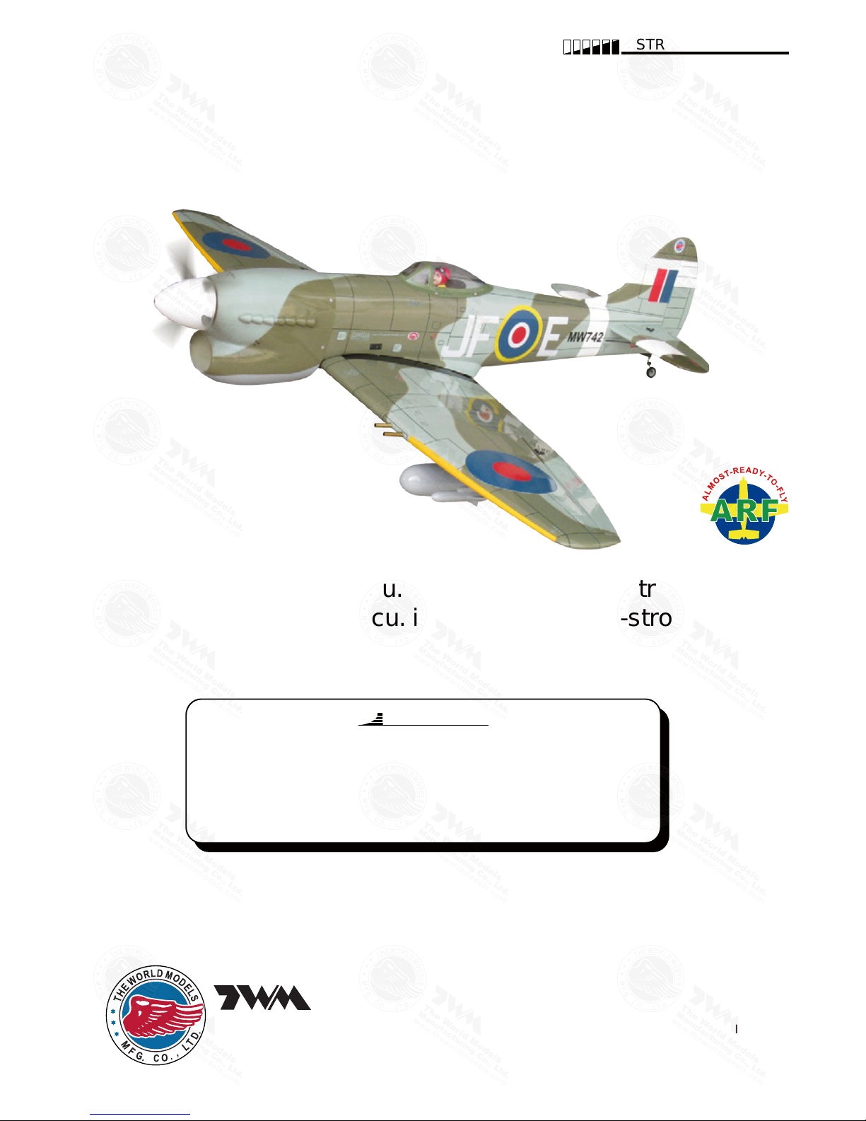
Hawker Tempest MK V
Hawker Tempest MK V
The World Models
Manufacturing Co., Ltd.
www.theworldmodels.com
Requires : 0.46-0.55 cu. in. displacement 2-stroke
0.70-0.81 cu. in. displacement 4-stroke
6-channel radio w/ 6 standard servos
and 1 low profile retract servo.
A317PO24531116
INDEX
BEFORE YOU BEGIN
BEFORE YOU BEGIN
PARTS LIST
ASSEMBLY
SAFETY PRECAUTIONS
P.1
P.2
P.3-P.13
P.14
Check all parts. If you find any defective or missing parts contact your local dealer. Please
DRY FIT and check for defects for all parts that will require CA or Epoxy for final assembly.
Any parts you find to be defective after the gluing process may be difficult to remove for
warranty replacement. The manufacturer will replace any defective parts, but will not extend
to the parts that are good before gluing to defective parts during assembly. Warranty will
not cover any parts modified by customer.
Symbols used throughout this instruction manual comprise of the following :-
Read through the manual before you begin, so you will have an overall idea of what to do.
1
2
3
P.1
Cut off shaded portion.
Ensure smooth non-binding
movement while assembling.
Apply instant glue
(C.A.glue, super glue.)
Assemble left and right
sides the same way.
Peel off shaded portion
covering film.
Pay close attention here!
Apply epoxy glue.
Must be purchased separately !
Drill holes with the specified
diameter (here: 3mm).
Pierce the shaded portion
covering film.
3mm
Do not overlook this symbol !
Warning!
Apply thread locker
Hawker Tempest MK V
Hawker Tempest MK V
A317PO24531116
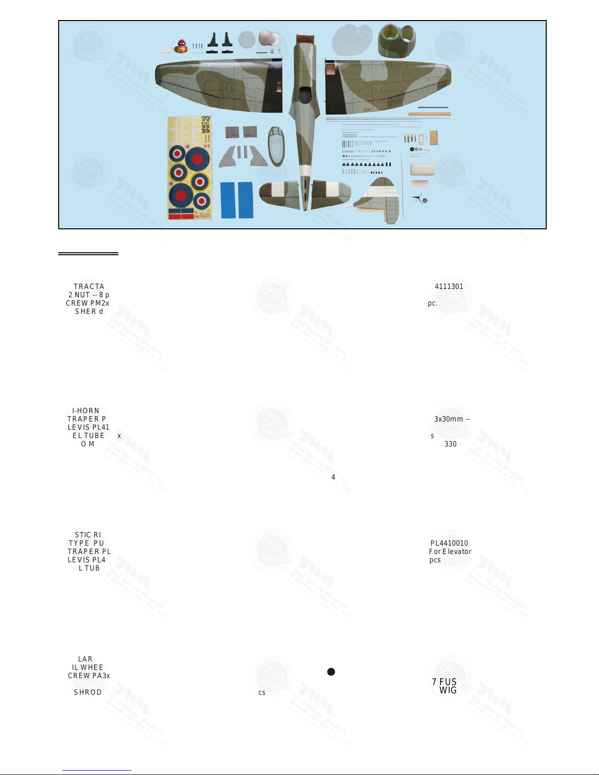
Parts List
P.2
COVERING:--
TOUGHLON STL 317 FUS
TOUGHLON STL 317 WIG
TOUGHLON STL 203 LIGHT GRAY
LIGHTEX SGX 203 LIGHT GRAY
LIGHTEX SGX 331 CUB YELLOW
LIGHTEX SGX 201 BLACK
LIGHTEX SGX 100 WHITE
LIGHTEX SGX 340 OLIVE DRAB
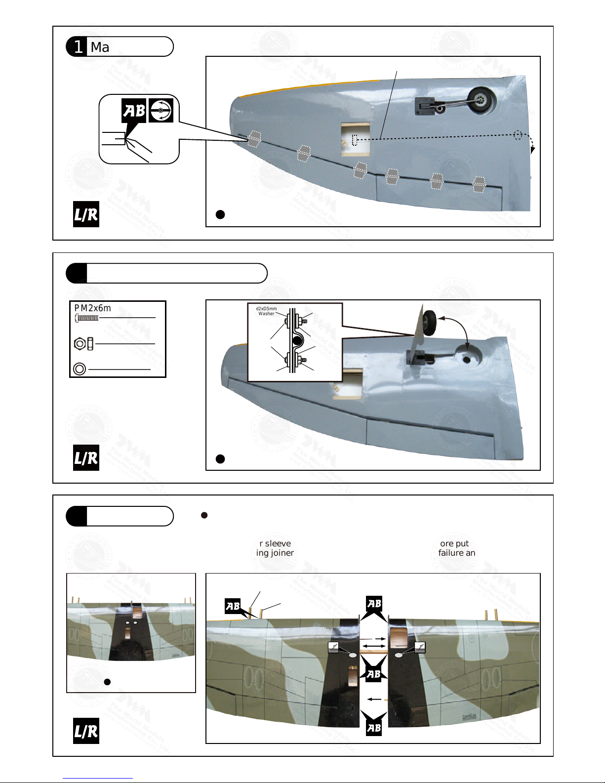
1.MAIN WING -- 1 pair
2.RETRACTABLE LANDING GEAR --1 pair
M2 NUT -- 8 pcs
SCREW PM2x6mm -- 8 pcs
WASHER d2xD5mm -- 16 pcs
MAIN LANDING GEAR COVERS -- 1 pair
PVC PLATE 0.5mm -- 2 pcs
3.WING JOINER 8x20x247mm -- 1 pc.
SCATTER-GUN(A) Ø8x36mm -- 2 pcs
SCATTER-GUN(B) Ø8x31mm -- 2 pcs
4.PUSHROD Ø1.8x85mm w/ Threads (ForAileron) -- 2 pcs
SCREW PB2x25mm -- 4 pcs
SCREW PB2x22mm -- 2 pcs
SCREW PWA2x8mm -- 8 pcs
TRI-HORN M3x14mm (S) PL4111221 -- 2 sets
STRAPER PL4112102 -- 2 pcs
CLEVIS PL4112103 -- 2 pcs
FUEL TUBE Ø6x5mm -- 4 pcs
SERVO MOUNTING PANEL PL5310000 -- 1 pair
*
OPTIONAL PARTS A317DTM :
DROP TANKS -- 1 pair
MISSILES -- 1 pair
PLYWOOD(A) 28x23x3mm -- 4 pcs
PLYWOOD(B) 20x23x3mm -- 4 pcs
SCREW PWM2.5x12mm -- 8 pcs
M2.5 NYLON INSERT LOCK NUT -- 8 pcs
WASHER d2.5xD8mm -- 8 pcs
5.PLASTIC RING PL4112023 -- 2 pcs
Y-TYPE PUSHROD Ø1.8x110mm (For Flap) -- 1 pc.
STRAPER PL4112102 -- 1 pc.
CLEVIS PL4112103 -- 2 pcs
FUEL TUBE Ø6x5mm -- 3 pcs
PLYWOOD 3x28x66mm -- 1 pcs
LINKAGE CONNECTOR Ø2.1mm HW7111060 -- 2 sets
6.VERTICAL FIN & RUDDER -- 1 set
FUSELAGE -- 1 pc.
7.STABILIZER & ELEVATOR -- 1 set
STABILIZER TUBE Ø8x180mm -- 1 pc.
8.TAIL LANDING GEAR -- 1 set
COLLAR Ø2.1mm w/ set screw -- 1 set
TAIL WHEEL Ø25mm PL3111250 -- 1 pc.
SCREW PA3x10mm -- 2 pcs
9.PUSHROD Ø1.8x550mm w/ Threads (
For Elevator) -- 2 pcs
SCREW PB2x22mm -- 4 pcs
SCREW PB2x20mm -- 2 pcs
TRI-HORN M3x14mm (S) PL4111221 -- 2 sets
CLEVIS PL4112103 -- 2 pcs
FUEL TUBE Ø6x5mm -- 2 pcs
10.PUSHROD Ø1.8x715mm w/ Threads (For Rudder) -- 1 pc.
SCREW PB2x20mm -- 3 pcs
TRI-HORN M3x22mm (S) PL4111301 -- 1 set
CLEVIS PL4112103 -- 1 pc.
FUEL TUBE Ø6x5mm -- 1 pc.
11.ENGINE MOUNT PL5111050 -- 1 set
SOCKET HEAD SCREW M4x25mm -- 4 pcs
WASHER d4xD9mm -- 4 pcs
BLIND NUT M4 HW1304125 -- 4 pcs
DOWEL D6x10mm -- 4 pcs
12.FUEL TANK 380cc -- 1 set
CABLE TIE 1.5x5x400mm -- 1 pc.
DOUBLE-SIDE TAPE 40x100mm -- 1 pc.
BATTERY TIE 200x13mm -- 1 pc.
SPONGE 80x200x10mm -- 1 pc.
13.SOCKET HEAD SCREW M3x30mm --
4 pcs
M3 NUT -- 8 pcs
WASHER d3xD7mm -- 8 pcs
THROTTLE PUSHWIRE Ø1.2x330mm -- 1 pc.
PLASTIC TUBE d2xD3x240mm -- 1 pc.
PLYWOOD 2x48.2x92.8mm -- 1 pc.
14.COWLING --1 pc.
TRANSPARENT 3D TEMPLATE -- 1 pc.
SCREW PWA2.6x12mm -- 4 pcs
SILICON GROMMET d1.5xD6.5mm PL1265035 -- 4 pcs
SPINNER Ø89mm PH22W0890 -- 1 set
15.LINKAGE CONNECTOR Ø2.1mm HW7111060 -- 1 set
16.PUSHROD CONNECTOR PL4410010 -- 1 set
PUSHROD Ø1.8x100mm (For Elevator) -- 1 pc.
STRAPER PL4112102 -- 2 pcs
FUEL TUBE Ø6x5mm -- 2 pcs
SPONGE 80x200x10mm -- 1 pc.
17.SCREW HM3x35mm -- 2 pcs
WASHER d3.2xD12mm -- 2 pcs
18.CANOPY -- 1 pc.
SCREW PWA2.3x8mm -- 4 pcs
SILICON GROMMET d1.5xD6.5mm PL1265035 -- 4 pcs
PILOT PC001050A -- 1 pc.
19.DECALS: A317DEC -- 1 set
A317PO24531116
Bottom View
Bottom View
P.3
Aileron Servo Lead
Scatter-Gun(A)
Ø8x36mm
Scatter-Gun(B)
Ø8x31mm
Pre-glued
M2 Nut
PM2x6mm Screw
8
8
16
d2xD5mm Washer
Completed
Please dry fit wing joiner into left and right wing to make sure they fit with the
proper dihedral angle, mark the wing joiner if necessary. Apply epoxy glue to
both sides of all surfaces in contact. Use a stick to apply the glue to inner side
of wing joiner sleeve, and apply the glue to wing joiner before putting them
together. Wing joiner not glued properly will lead to wing failure and plane crash.
PM2x6mm
M2 Nut
M2 Nut
d2xD5mm
Washer
d2xD5mm
Washer
d2xD5mm
Washer
Main Wing
1
Main Wing
3
Retractable Landing Gear
2
A317PO24531116

Aileron Servo & Optional Drop Tanks And Missiles
Bottom View
P.4
4
Straper
Fuel Tube
6x5mmØ
Ø1mm pilot holes for World Models tri-horn are
pre-drilled. Please look for pin-hole marks at
under side of control surfaces.
1.5mm
TWM PL8210010
CLEVIS WRENCH
Pushrod
1.8x 85mm
Fuel Tube
Clevis
6x5mm
PB 2 x 25mm
PB 2 x 22mm
Tri-horn
M3 x 14mm(s)
PWA2x8mm
PWA2x8 mm Screw
4
PB2x25mm Screw
4
PB2x22mm Screw
2
Plywood
Missile
M2.5
Nylon Insert Lock Nut
PWM2.5x12mm
d2.5xD8mm
Washer
d2.5xD8mm
Washer
Bottom View
Optional Drop Tanks And Missiles
Plywood (A)
Plywood (B)
A317PO24531116
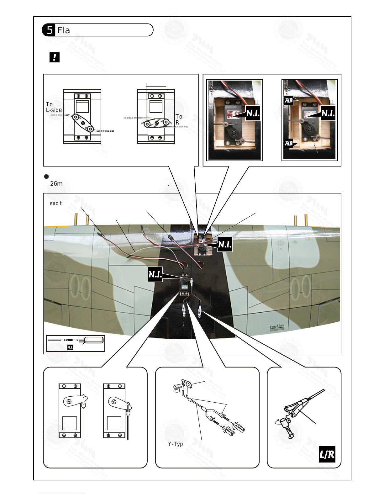
Flap & Retract Servos
P.5
5
TWM PL8210010
CLEVIS WRENCH
Lead to retract servo
Lead toAileron Servo
Lead toAileron Servo
Please refer to attched sheet for linkage connector installation
Select the servo horn that will give
26mm travel when rotates through 180o.
Flaps up Flaps Down
Lead to Flap Servo
Fuel Tube
Ø6 x 5mm
Straper
Y-Type Pushrod
Ø1.8 x 110mm
Clevis
To
L-side
To
R-side
WheelsupPosition
To
L-side
To
R-side
WheelsdownPosition
26mm
or
Plywood 3x28x66mm
A317PO24531116

Vertical Fin & Rudder
P.6
6
Stabilizer & Elevator
7
B B'
B=B'
(Stabilizer)
(Main Wing)
C C'
C=C'
Temporaryinstall the main wing,adjust leveling of the stabilizer
to make it as parallel to the main wing as possible
A A'
A=A'
Completed
Pre-glued
Completed
Pre-glued
Stabilizer Tube
Ø8x180mm
A317PO24531116

Tail Landing Gear
P.7
8
Rudder Pushrod
10
Elevator Pushrod
9
Ø1mm pilot holes for World Models tri-horn are pre-drilled.
Please look for pin-hole marks at under side of control surfaces.
PA3x10mm Screw
2.1mm
3mm Set Screw
Collar
1.5mm
2.5mm
PA3x10mm
2.1mm Collar
Tail Wheel
Ø
25mm
3mm Set Screw
2
1
1
PB2x22mm Screw
4
Elevator Pushrod
Ø1.8x 550mm
Fuel Tube
Ø6x5mm
PB 2 x 22mm
Clevis
PB 2 x 20mm
Tri-horn
M3 x 14mm
PB2x20mm Screw
2
Bottom View
Bottom View
Ø1mm pilot holes for World Models tri-horn are pre-drilled.
Please look for pin-hole marks at side of control surfaces.
PB2x20mm Screw
3
Bottom View
PB 2 x 20mm
Clevis
Fuel Tube
Tri-horn
M3 x 14mm
Rudder Pushrod
Ø1.8x 550mm
Ø6x5mm
A317PO24531116

P.8
Engine Mount
11
Fuel Tank
12
M4x25mm Socket Head Screw
d4xD9mm Washer
M4 Blind Nut
4
4
4
Apply thread locker to screws
Blind nuts are off-centered to keep
the spinner at the fuselage axis.
A: Inverted mount with Pitts
type muffler.
B: Inverted mount for stock
muffler installation
A
B
UP
Dowel
d6x10mm
Engine Mount
PL5111050
d4xD9mm Washer
M4 Blind Nut
Socket Head Screw
M4x25mm
1 2
3
Battery Tie
Cable Tie 1.5x5x400mm
Fuel Tank 380cc
Fuel Tank
380cc
Battery
Double-side Tape
40x100mm
Sponge
Bottom View
Bottom View
Bottom View Bottom View
A317PO24531116

P.9
Engine
13
Cowling
14
M3x30mm Socket Head Screw
d3xD7mm Washer
4
8
8
Installed Engine Position
123mm
4.84in
Throttle Pushwire
Ø1.2x330mm
Plastic Tube
d2xD3x240mm
M3x30mm Socket Head Screw
d3xD7 Washer
M3 Nut
M3Nut
PWA2.6x12mm Screw
4
First insert the grommet to the cowling then apply screw.
Please refer to the attached sheet for usage of the
transparent 3D template.
d1.5xD6.5mm
Grommet
Cowling
Spinner
Ø89mm
Fuselage
PWA2.6x12mm
4
dx1.5xD6.5mm
Silicon Grommet
Plywood
2x48.2x92.8mm
A317PO24531116

P.10
Servo Set
15
Radio Equipment
16
Throttle Pushwire
Ø1.2x330mm
Throttle Pushwire
3x3mm Set Screw
Washer
2mm
Washer
2mm
M2 Nut
Throttle Servo.
1.5mm
Please refer to the attached sheet for linkage connector installation.
3x3mm Set Screw
M2 Nut
Linkage Connector
1
1
1
2
2mm Washer
Install and arrange the servos as shown in the diagram.
Sponge
10x80x200mm
Switch
Throttle Servo
Plastic Tube
d2xD3x240mm
Receiver
Front
Fuel Tube
Ø6x5mm
Straper
Elevator Pushrod
Ø1.8x550mm
Rudder Pushrod
Ø1.8x715mm
Rudder Servo
Elevator Servo
KM2x8mm
M2Nut
Elevator Pushrod
Ø1.8x100mm
Elevator Servo
Pushrod Connector
J1
J2
J1(Pushrod Ø1.8x100mm)
J2(Pushrod Ø1.8x550mm)
Charge Receptacles
KP0041300
Fuel Tube
6x5mm
Straper
Pushrod
Bottom View
A317PO24531116

P.11
Main Wing
17
Canopy
18
Bottom View
Bottom View
HM3x35mm Screw
d3.2xD12mm Washer
d3.2xD12mm Washer
2
2
HM3x35mm
First insert the grommet to the canopy then apply screw.
PWA2.3x8mm Screw
4
4
d1.5xD6.5mm Silicon Grommet
Silicon Grommet
d1.5xD6.5mm
PWA2.3x8mm
Pilot
1mm
A317PO24531116

P.12
Wing Setting
19
A=A` B=B` C=C`
C`C
B B`
A`A
A317PO24531116

P.13
Control Throws
20
C.G.
21
The ideal C.G. position is 85mm ( 3.35 in ) behind the leading
edge measured at where the wing meets the fuselage. In order
to obtain the C.G. specified, add weight to the fuselage or move
the battery position. Check the C.G. before flying.
85mm
C.G.
18mm
18mm
Elevator
25mm
25mm
Rudder
12mm
12mm
Ailerons ( away from fuselage )
35mm
Flaps (near fuselage )
Adjust the control throws as shown in the diagram. These throws are good for general
flying. You can adjust according to your personal preference.
Measure C .G. with the wheels in retracted position
3.35 in
A317PO24531116

P.14
Important Safety Precautions
First time flyer should never fly by himself / herself. Assistance from experienced flyer is
absolutely necessary.
Pre - flight adjustment must be done before flying, it is very dangerous to fly a badly
adjusted aircraft.
pre -
Make sure the air field is spacious, never fly the plane too close to people and never get
too close to a running propeller.
If you find wrinkles on the covering as a result of
weather changes, you can use hot iron
to remove the wrinkles. Please begin with lower temperature setting and gradually raise
the temperature until the wrinkles are gone. Too hot an iron may damage the covering.
Don,t use hot iron near the seams or edges, hot iron will melt the glue and shrink the covering at the
same time, causing the seams to pull away.
Check and re-tighten up all factory assembled screws, use thread locker if necessary.
is specially designed to be powered by 2c 0.46-0.55 or 4c 0.70-0.81
engine,using a more powerful engine does not mean better performance.
In fact, over powered
engine may
cause severe damage and injuries.
When Flaps are lowered, nose of model will rise. The nose-up varies with the speed at which
the model is flying when you lower the flaps and the extent to which they are lowered. Check
effect of flaps at higher altitude to avoid surprises during landing. You may apply down trim
of the elevator to compensate for the nose-up effect when
lowering the flaps. Taking off with
flaps lowered is not recommended, as the increased drag may require a longer runway and
more engine power for the model.
Should you require to bend the landing gear wire, please insert a round metal bar into the
spring ring and apply force there as leverage. Bending the wire directly may damage the
mounting block structure.
Round metal bar
Landing Gear
Should you need to bend the landing gear wire, use the radio control to open or
close the gear to 25% from fully retracted position and switch off the receiver. It
is safe to bend the wire in this position. Bending the wire in fully open position
may damage the supporting structure.
#
#
#
#
#
#
#
Warning!
Hawker Tempest MK V
Hawker Tempest MK V
A317PO24531116

LINKAGE CONNECTOR
HW7111050 & HW7111060
After fastening the round nut, make sure that
the linkage connector can rotate freely.
Drill 2mm hole at servo horn.
Insert linkage connector
into servo horn.
Make sure shoulder of
screw is cleared from
servo horn.
Add washer to reduce
play if necessary.
Shoulder
Tighten up the round nut
against the shoulder. Apply
CA or permanent thread
locker.
A317PO24531116

Product Registration Form (US Customers)
We would like to share with you any relevant information regarding your model, including
product news and free upgrade parts when applicable. Please fill in the following and
send to AirBorne Models, 4749-K,Bennett Drive, Livermore, CA 94551 USA.
1. Name:______________________________________________
2. Address:____________________________________________
3. Phone #:____________________ E-mail:__________________
4. Model:______________________________________________
Wing QC#__________ Fuselage QC# _______________________
(QC numbers are stamped on wing and fuselage)
5. Date of Purchase:_____________________________________
6. Store Name: _________________________________________
Please call AirBorne Models at 925 371 0922 for any assistance in filling this
form.Thank you very much for purchasing our product.
A317PO24531116

This transparent 3D template
is used for position guidance
of the actual cutting of the
pre-painted cowling.
Usage of the transparent 3D template
Simply cut the transparent 3D template to fit your engine and
exhaust pipe, then slide onto the actual cowling and use as
template to mark the openings required for final cutting.
1 2
3 4
A317PO24531116

Optional Parts
Clevis Wrench
Code No. Size Package
PL8210010 1 set
Small Clevis
Large Clevis
Field Stand
Code No. Size Package
Code No. Size Package
MS9111450 600 x 240 x 350mm 1 pc
( ACCESSORIES)
180mm Extension
Code No. Size Package
KW0011800 180mm 1 set
Charge Receptacles
Code No. Size Package
KP0041300
180mm Y-Cord
Code No. Size Package
KW0021800 180mm 1 pc
Special tool for clevis installation.
Suitable for standard and small
(EP) clevis.
Fuel Filler
Code No. Size Package
PL8110030 15 x 22 x 49mm 1 x 1 pc
SV4031 40.6 x 20 x 37mm 1 set
Speed : 0.17 sec / 60° @4.8V
0.14 sec / 60° @6.0V
Torque : 3.2kg.cm / 44.8 oz - in @4.8V
4.1kg.cm / 57.4 oz - in @6.0V
Size : 40.6 x 20 x 37mm /
1.60 x 0.79 x 1.46 in
Weight : 39.4 g / 1.39 oz
Standard Servo
A317PO24531116

The World Models
Manufacturing Co., Ltd.
www.theworldmodels.com
A317PO24531116
 Loading...