

TWM EXTRA 330L 60 Instruction Manual
Wing Span
Wing Area
Flying Weight
Fuselage Length
65.0 in / 1650mm
797 sq in / 51.4 sq dm
8.2 lbs / 3720g
56.0 in / 1420mm
Warning !This model is not a toy.
It is designed for maximum performance. Please seek advice if one is not familiar with this kind
of engine powered precision model. Operating this model without prior preparation may cause
injuries. Remember, safety is the most important thing. Always keep this instruction manual at
hand for quick reference.
* Speci ficatio ns are subj ect to chan ge withou t notice.*
Specifications
INSTRUCTION MANUAL
E
A
D
R
-
Y
T
-
T
S
O
O
-
F
M
L
L
Y
A
0.6 -0.75 cu. in. displacement 2-stroke
0.91 cu. in. displacement 4-stroke
0
R s - radio w/ standard equire : 4 channel 5 servos
FACTORY PRE-FABRICATED
ALMOST-READY-TO-FLY (ARF) SERIES
MADE IN CHINA
A156 SP O2589 110 8
P.1
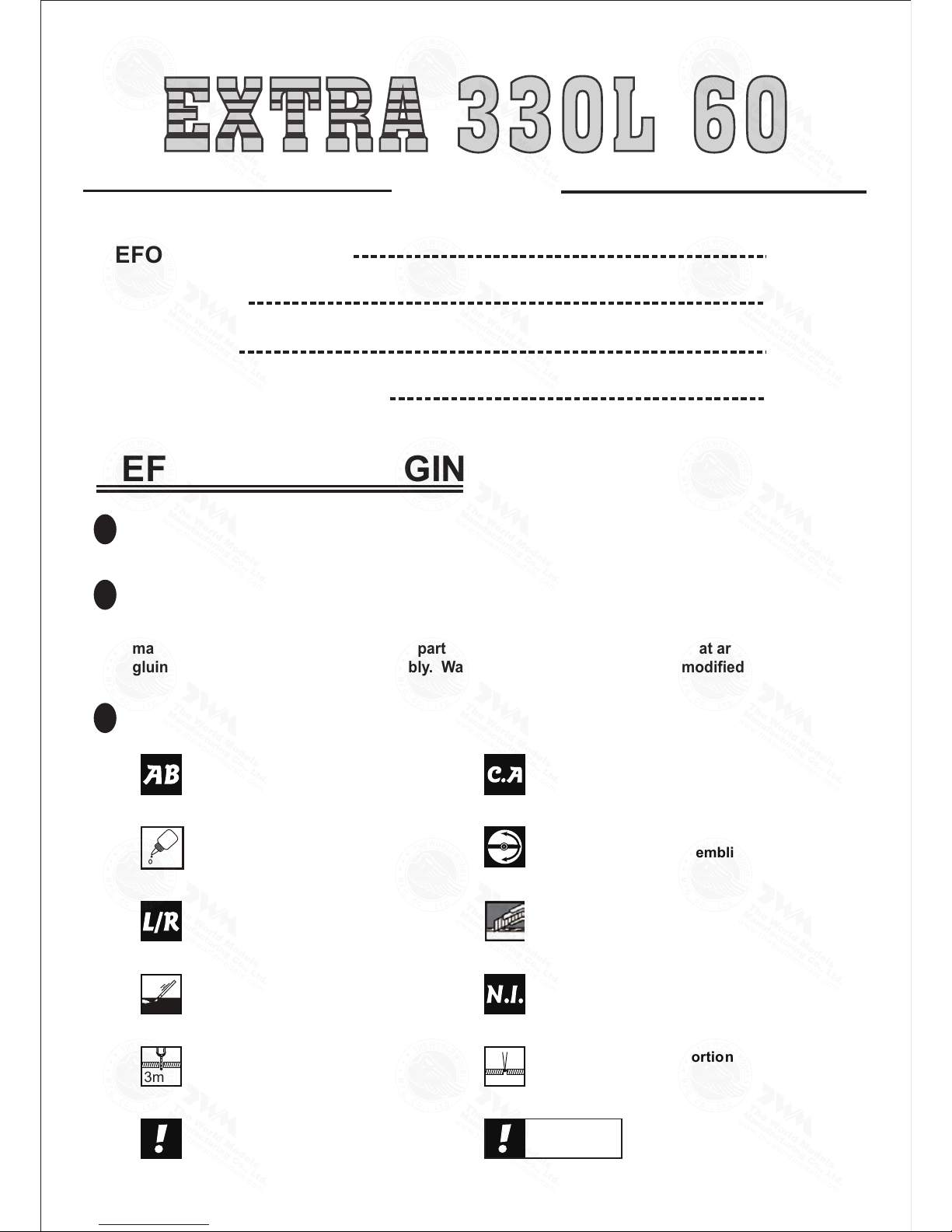
Appl
y
thread locke
r
Apply epoxy glue.
Pierce the shaded portion
covering film.
Apply instant glue
(C.A.glue, super glue.)
Ensure smooth non-binding
movement while assembling.
Do not overlook this symbol !
Check all parts. If you find any defective or missing parts contact your local dealer. Please DRY FIT
and check for defects for all parts that will require CA or Epoxy for final assembly. Any parts you
find to be defective after the gluing process may be difficult to remove for warranty replacement. The
manufacturer will replace any defective parts, but will
not
extend to the parts that are good before
gluing to defective parts during assembly. Warranty will not cover any parts modified by customer.
Read through the manual before you begin, so you will have an overall idea of what to do.
Symbols used throughout this instruction manual comprise of the following : -
1
2
3
Assemble left and right
sides the same way.
Peel off shade d portion
covering film.
Drill holes with the specified
diameter (here: 3mm) .
Pay close attention here!
Cu
t
of
f
shaded
portion
.
Mus
t
b
e
purchase
d
separatel
y
!
Warning!
3mm
P. 3 -11
INDEX
BEFORE YOU BEGIN
PARTS LIST
ASSEMBLY
SAFETY PRECAUTIONS
P. 1
P. 2
P.11
BEFORE YOU BEGIN
A156 SP O2589 110 8
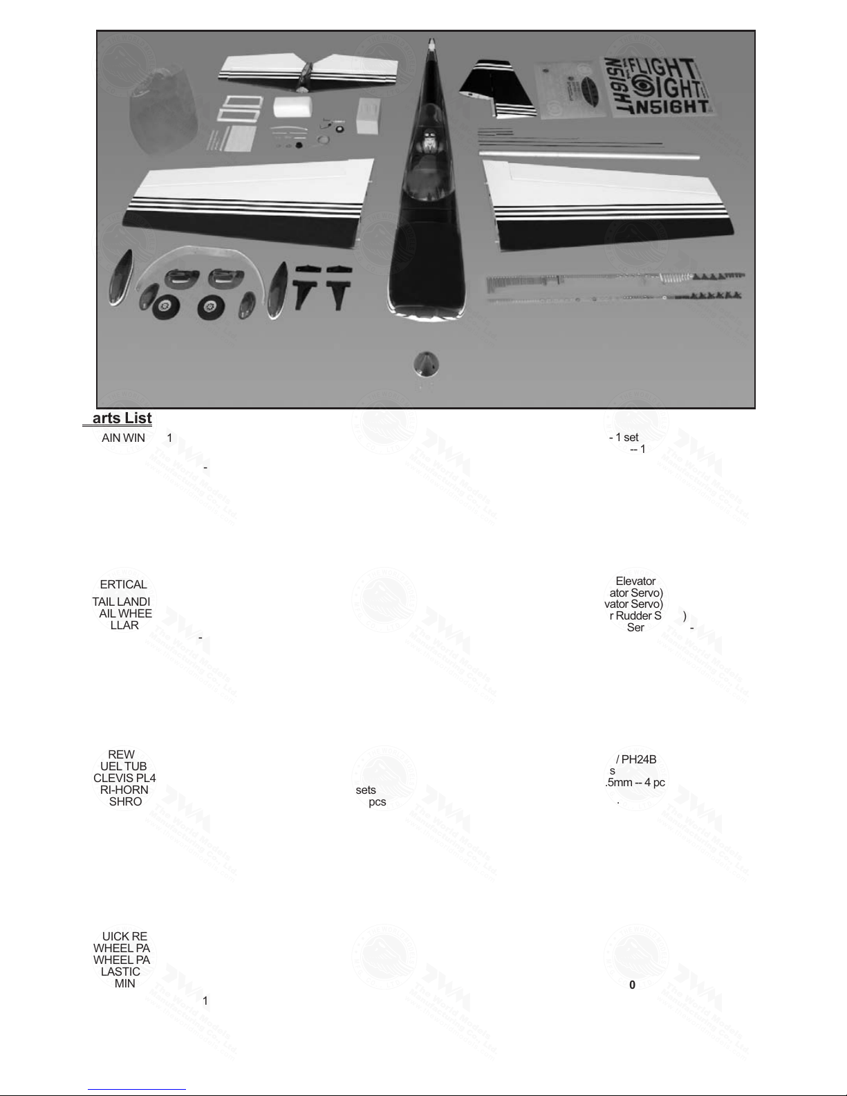
Parts List
COVERIN G:- -
TOUGHLON ST L 100 W HITE
TOUGHLON ST L 201 B LACK
TOUGHLON ST L 241 T URQUOISE
TOUGHLON ST L 360 V IOLET
TOUGHLON ST L 311 FE RRARIRED
TOUGHLON ST L 351 D ARK BLUE
P.2
1. MAIN WING -- 1 pair
2. SCREW PB2x25mm -- 6 pcs
SCREW PWA2x8mm -- 8 pcs
FUEL TUBE Ø6x5mm -- 4 pcs
STRAPER PL4112102 -- 2 pcs
CLEVIS PL4112103 -- 2 pcs
TRI-HORN M3x14mm PL4111185 -- 2 sets
PUSHROD Ø1.8x120mm w/ Threads (For Aileron) -- 2 pcs
SERVO MOUNTING PANEL PL5310000-- 1 pair
3. STABILIZER & ELEVATOR -- 1 set
FUSELAGE -- 1 pc.
4. VERTICAL FIN & RUDDER -- 1 set
5. TAIL LANDING GEAR PL7100001 -- 1 set
TAIL WHEEL Ø30mm -- 1 pc.
COLLAR Ø2.1mm w/ set screw -- 1 set
SCREW PA3x12mm -- 2 pcs
6. SCREW PM2x25mm -- 3 pcs
M2 NUT -- 3 pcs
FUEL TUBE Ø6x5mm -- 2 pcs
CLEVIS PL4112103 -- 2 pcs
TRI-HORN M3x14mm (w/ o-Base For Rudder) PL4111185 -- 2 sets
RIGGING COUPLER Ø1.8x27mm w/ Threads HW4201304 -- 2 pcs
COPPER TUBE d2.5xD3.2x8mm --2 pcs
WIRE Ø1x700mm (For Rudder) -- 2 pcs
7. SCREW PB2x25mm -- 6 pcs
FUEL TUBE Ø6x5mm -- 2 pcs
CLEVIS PL4112103 -- 2 pcs
TRI-HORN M3x14mm (For Elevator) PL4111185 -- 2 sets
PUSHROD Ø1.8x600mm w/ Threads (For Elevator) -- 2 pcs
8. MAIN LANDING GEAR HW2404045 -- 1 set
MAIN LANDING GEAR COVER -- 1 pair
WHEEL Ø76mm PL3111760 -- 2 pcs
COLLAR Ø5.1mm w/ set screw -- 4 sets
SCREW HM4x16mm -- 4 pcs
SCREW PM5x43mm -- 2 pcs
SCREW PWA2.3x8mm -- 14 pcs
SCREW KA2.3x8mm -- 4 pcs
M5 NUT -- 2 pcs
WASHER d5xD12mm -- 4 pcs
QUICK RELEASE NYLON RIVET PL1208042 -- 4 pcs
WHEEL PANTS -- 1 pair
WHEEL PANT DECORATIVE COVER -- 1 pair
PLASTIC WHEEL COLLAR d5.1xD9x3mm -- 2 pcs
ALUMINUM PLATE 1mm -- 2 pcs
9. ENGINE MOUNT PL5111070 -- 1 set
SOCKET HEAD SCREW M4x25mm -- 4 pcs
WASHER d4xD12mm -- 4 pcs
M4 BLIND NUT -- 4 pcs
WOODEN DOWEL Ø5.5x8mm (For Firewall) -- 4 pcs
10. FUEL TANK 380cc PL1111380 -- 1 set
DOUBLE-SIDED TAPE 40x100mm -- 1 pc.
CABLE TIE 1.5x5x400mm -- 1 pc.
11. SOCKET HEAD SCREW M4x30mm -- 4 pcs
WASHER d4xD9mm -- 8 pcs
M4 NUT -- 8 pcs
PLYWOOD 2x93.8x120mm (Engine Box Upper Plate) (F21) -- 1 pc.
THROTTLE PUSHWIRE Ø1.2x350mm -- 1 pc.
PLASTIC TUBE d2xD3x140mm -- 1 pc.
12. LINKAGE CONNECTOR Ø2.1mm HW7111060 -- 1 set
13. BALSA 6x6x41 (For Elevator & Rudder Servo Stand) (F43) -- 4 pcs
PLYWOOD 3x57x154.6mm (For Elevator Servo)( F44A) -- 1 pc.
BALSA 6x6x143.6mm (For Elevator Servo) (F45B) -- 1 pc.
BALSA 6x6x150.3mm (For Elevator Servo) (F45C) -- 1 pc.
PLYWOOD 3x61x144.6mm (For Rudder Servo) (F44) -- 1 pc.
BALSA 6x6x131.5mm (For Rudder Servo) (F45) -- 1 pc.
BALSA 6x6x140.7mm (For Rudder Servo) (F45A) -- 1 pc.
COPPER TUBE d2.5xD3.2x8mm -- 2 pcs
STRAPER PL4112102 -- 1 pc.
FUEL TUBE Ø6x5mm -- 1 pc.
SPONGE 60x70x160mm (For Radio Equipment) -- 1 pc.
PUSHROD Ø1.8x100mm (For Elevator) -- 1 pc.
RIGGING Z BEND Ø1.8x27mm (For Rudder ) HW4201303 -- 2 pcs
PUSHROD CONNECTOR 4x9x20mm PL4410010 -- 1 set
14. COWLING -- 1 pc.
TRANSPARENT 3D TEMPLATE -- 1 pc.
SPINNER Ø70mm PH24W0700 / PH24B0700 -- 1 set
SCREW PWA2.6x12mm -- 4 pcs
SILICON GROMMET d1.5xD6.5mm -- 4 pcs
15. WING TUBE Ø22x814mm -- 1 pc.
WIRE Ø0.8mm -- 2 pcs
SELF-TIGHTENING LATCHING PIN -- 2 pcs
16. CANOPY -- 1 pc.
PILOT PC001085A -- 1 pc.
SCREW PM2.5x25mm -- 2 pcs
SCREW PWA2.3x8mm -- 6 pcs
SILICON GROMMET d1.5xD6.5mm -- 6 pcs
WASHER d2.5xD8mm -- 2 pcs
DOUBLE-SIDED TAPE 900mm -- 1 pc.
PLASTIC PLATE (For Pilot Stand) -- 1 pc.
17. DECALS: A156DEC -- 1 set
A156 SP O2589 110 8
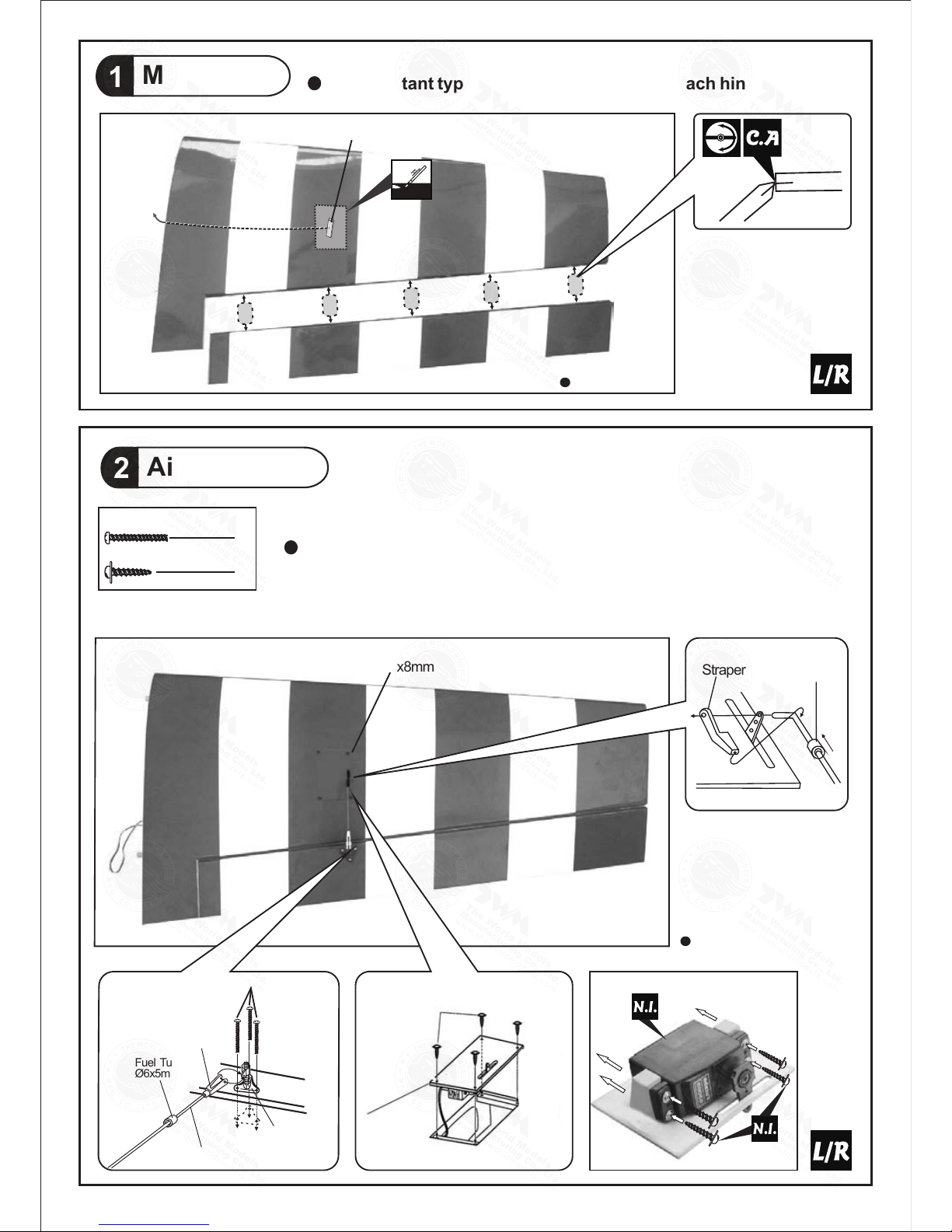
Main Wing
1
Aileron Servo
2
Botto m View
6
PB2x25mm Screw
8
PWA2x8mm Screw
Fuel Tube
Ø6x5mm
PB2x25mm
Tri-horn
M3x14mm
Clevis
Pushrod
Ø1.8x120mm
Fuel Tube
Ø6x5mm
Straper
PWA2x8mm
1 m m
PWA2 x 8mm
Aileron S erv o Lead
Botto m View
P.3
Ø1mm pilot holes for World Models tri-horn are pre-drilled.
Please look for pin-hole marks at under side of control surfaces.
Apply instant type CA gule to both sides of each hinge.
A156 SP O2589 110 8
App ly ins ta nt t yp e CA g lu e to
bot h s ide s o f e a ch hi nge .
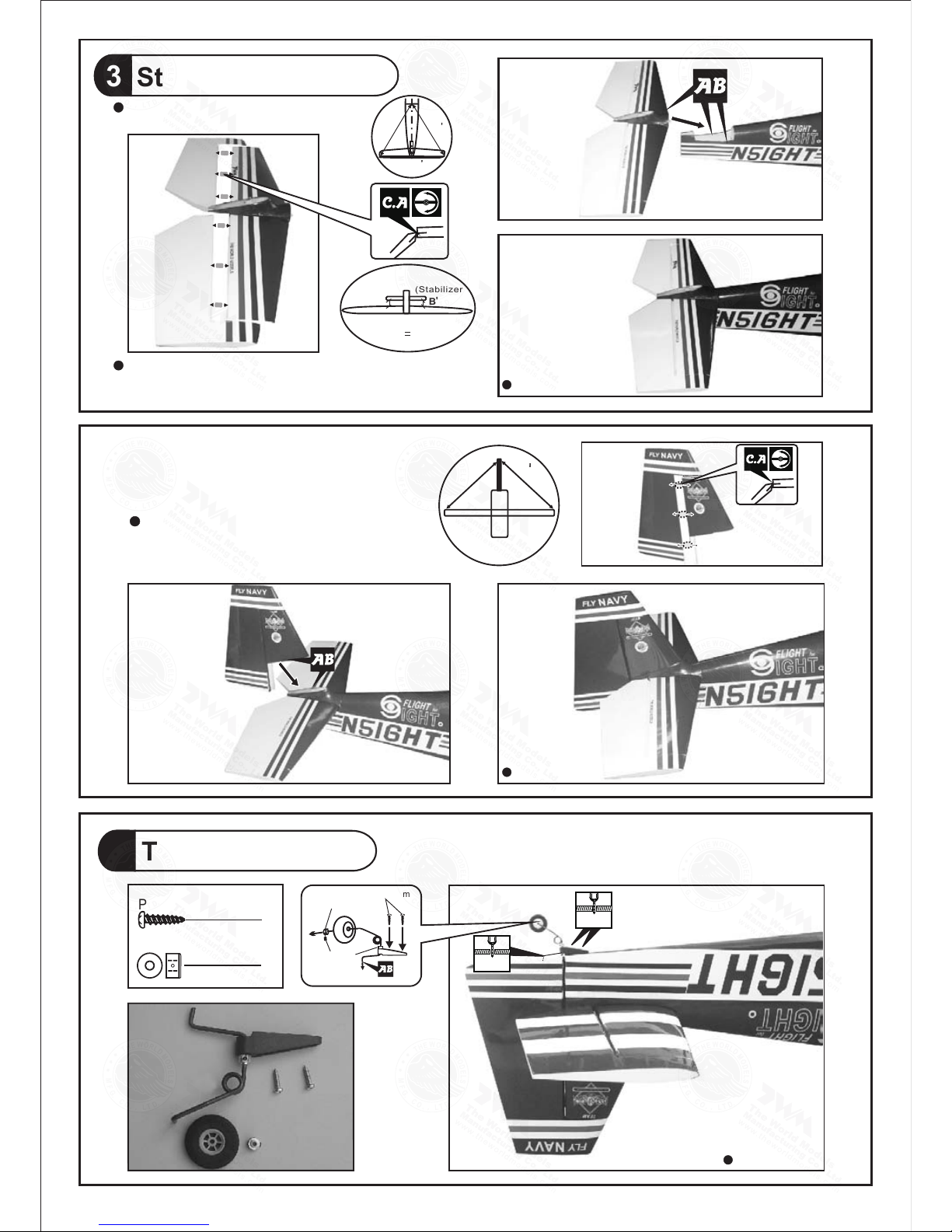
Stabilizer Elevator &
3
Apply i n s t a n t typ e C A g l u e to
both s i d e s of e a c h hinge.
A=A
A
A
Completed
(St abili zer)
(Ma in Wing )
B
B'
B
B
Tempo rary inst all the main wing, adjust l eveling
of the st abilizer to ma ke it as para llel to the main
wing as possible.
C=C'
C
C
Completed
5
Tail Landing Gear
2.1mm Collar
2
PA3 x 12m m Screw
2
M3 x 3mm
Set Screw
PA3 x 12mm
2.1mm Collar
Bottom View
P.4
1.5mm
2.1mm
A156 SP O2589 110 8
 Loading...