

Page 1
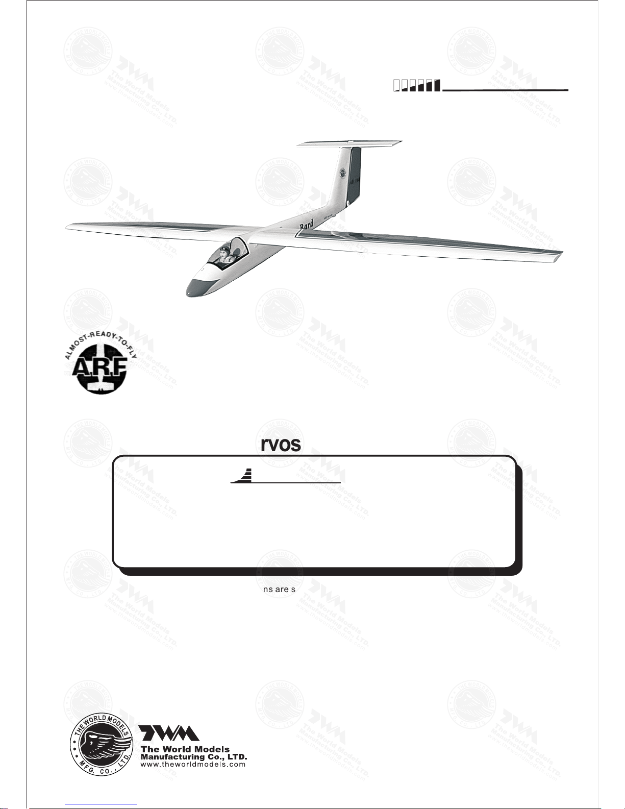
Specifications
Wing Span
Wing Area
Flying Weight
Fuselage Length
80 in / 2030 mm
409 sq in / 26.4 sq dm
2.6 lbs / 1200 g
36.5 in / 925 mm
Warning !This model is not a toy.
It is designed for maximum performance. Please seek advice if one is not familiar with this kind
of engine powered precision model. Operating this model without prior preparation may cause
injuries. Remember, safety is the most important thing. Always keep this instruction manual
at hand for quick reference.
* Specifications are subject to change without notice.*
INSTRUCTION MANUAL
Bard
Requires : 3 -channel radio w/ 2 standard servos and
2 mini servos
FACTORY PRE-FABRICATED
ALMOST-READY-TO-FLY (ARF) SERIES
MADE IN CHINA
Page 2
P. 1
Bard
P. 3- 11
Check all parts. If you find any defective or missing parts contact your local dealer. Please DRY FIT
and check for defects for all parts that will require CA or Epoxy for final assembly. Any parts you
find to be defective after the gluing process may be difficult to remove for warranty replacement. The
manufacturer will replace any defective parts. but will
not
extend to the parts that are good before
gluing to defective parts during assembly.
INDEX
BEFORE YOU BEGIN
PARTS LIST
ASSEMBLY
SAFETY PRECAUTIONS
P. 1
P. 2
P. 11
BEFORE YOU BEGIN
Read through the manual before you begin, so you will have an overall idea of what to do.
Symbols used throughout this instruction manual comprise of the following : -
1
2
3
3mm
Do not overlook this symbol!
Cut off shaded portion.
Peel off shaded portion
covering film.
Pay close attention here!
Pierce the shaded portion
covering film.
Must be purchased separately!
Drill holes with the specified
diameter (here: 3mm).
Ensure smooth non-binding
movement while assembling.
Apply instant glue
(C.A.glue, super glue.)
Assemble left and right
sides the same way.
Apply epoxy glue.
Apply thread locker
Warning!
Page 3
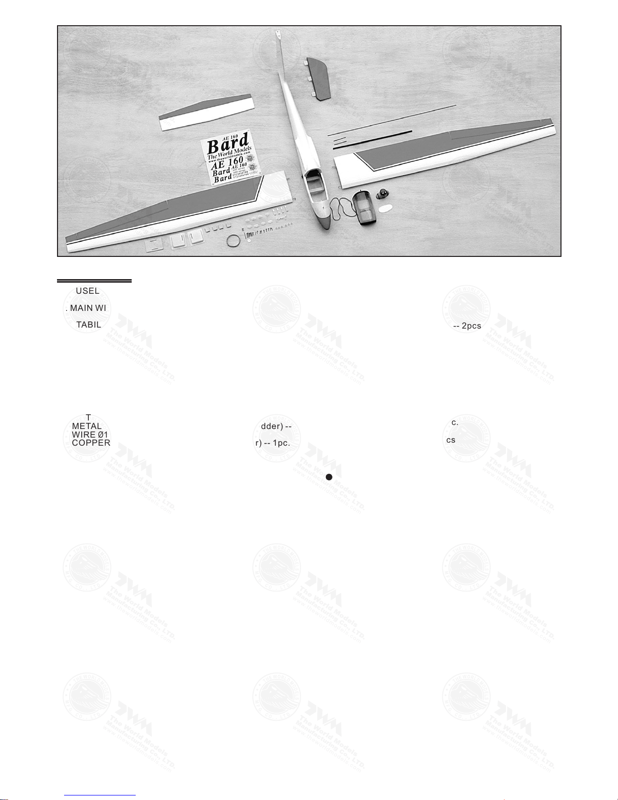
1. FUSELAGE -- 1pc.
2. MAIN WING -- 1pair
3. STABILIZER & ELEVATOR -- 1 set
4. RUDDER -- 1pc.
5. PLILOT (#PC001050A) -- 1pc.
6. CANOPY & COCKPIT -- 1s et
7.AILERON SERVO COVER -- 2 pcs
8. PUSHROD & PULLWIRE:- METAL ROD Ø1.8X55mm (For Aileron) -- 2pcs
METAL ROD Ø1.8X580mm w/Threads (For Rudder) -- 1pc.
WIRE Ø1.5mm (For Elevator) -- 1pc.
COPPER TUBE d2XD2.4X8mm (For Elevator) -- 1pc.
9. WOODEN PART S: - BALSA 5X5X48mm (For Radio) -- 2pcs
PLYWOOD 3X48X70mm (For Radio) -- 1pc.
WOODEN 8X13X16mm (For Aileron Servo) -- 2pcs
WOODEN 7X13X16mm (For Aileron Servo) -- 2pcs
Parts List
P.2
10. PLASTIC PART S: - CLEVIS -- 4pcs
STRAPER -- 2pcs
HORN -- 4pcs
RUBBER BAND D60X4mm -- 2pcs
FUEL TUBE Ø6X5mm -- 6 pcs
11. METAL PARTS:- LINKAGE CONNECTOR 2.1mm -- 2sets
WING TUBE Ø6X353mm -- 2pcs
SCREW PM2X12mm -- 2pcs
SCREW PM2X16mm -- 4pcs
SCREW PM2X20mm -- 2pcs
SCRRW PM3X20mm-- 1pc.
SCREW PWA 2X 8m m -- 8 pc s
WAS HE R d3 XD 12 mm - - 1p c.
12.FUEL TUBE Ø6X5mm -- 7pcs
13. DECALS -- 1set
COVE RING:- LIGH TEX SGX 100 WHITE
LIGH TEX SGX 312 BRIGH T RED
LIGH TEX SGX 201 BLACK
Page 4
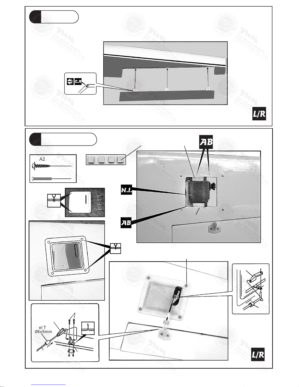
Aileron
1
PWA2x8mm Screw
PM2x16mm Screw
8
4
Wooden 8x13x16mm
1mm
PWA2x8mm
Straper
Fuel
Tube
PM2x16mm
Clevis
Fuel Tube
Ø6x5mm
Metal Rod
Ø1.8x55mm
Horn
Aileron Servo
2
2.5mm
P.3
Wooden 7x13x16mm
Page 5
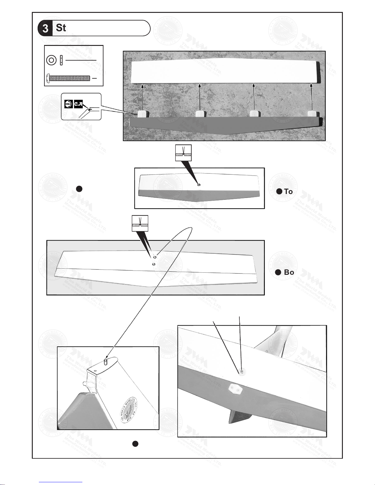
Stabilizer / Elevator
3
d3xD12mm Washer
1
1
PM3x20mm Screw
Completed
Top View
Bottom View
PM3x 20mm
d3xD 12mm
Top View
P.4
Page 6
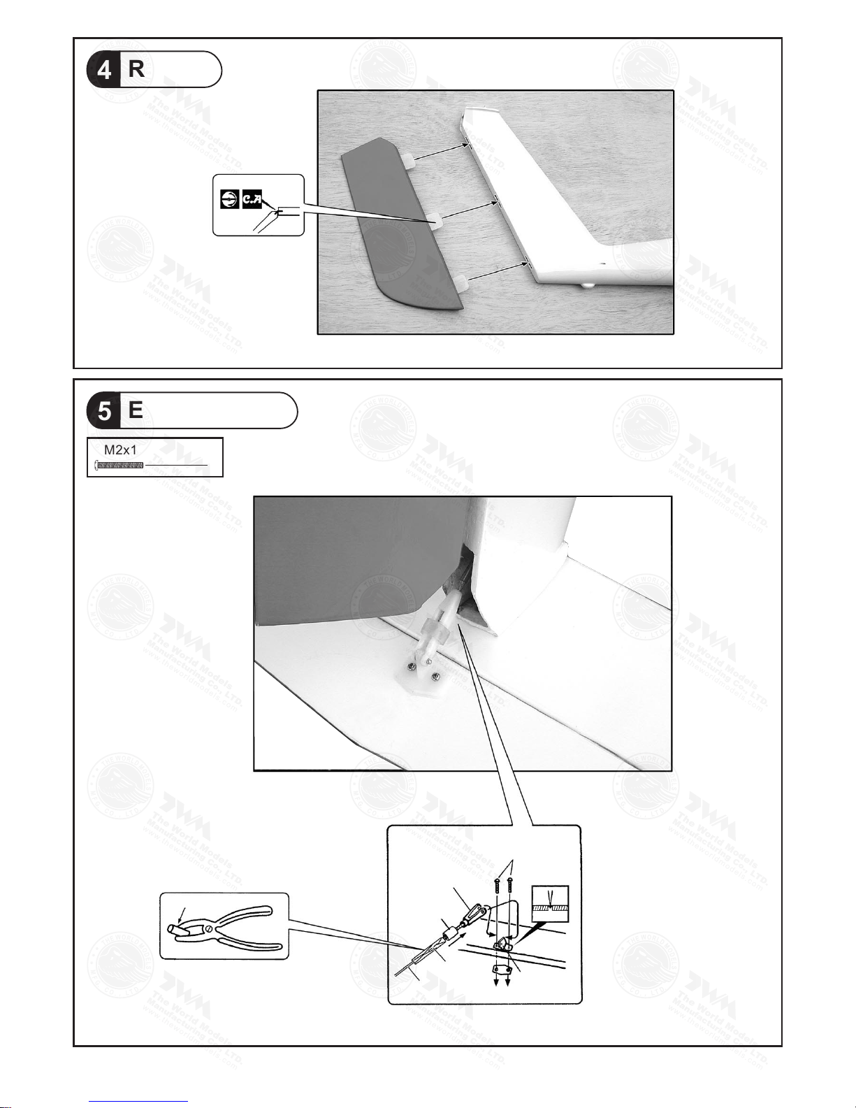
Rudder
4
Elevator Linkage
5
PM2x12mm Screw
2
Clamp the copper tube
PM2x 12mm
Clev is
Fuel Tu be
Ø6x5m m
Tube
Wire
Horn(Short)
P.5
Page 7
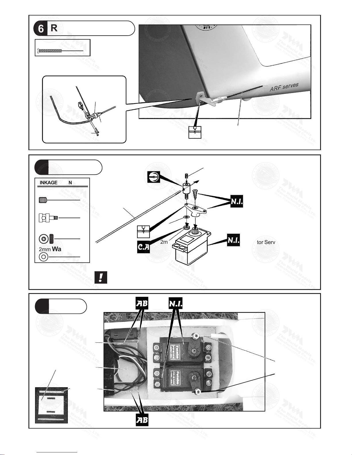
PM2x20mm Screw
2
Rudder Pushrod
6
Fuel Tu be
Ø6x5m m
Clev is
PM2x 20mm
2mm
Rudd er Pushrod
Ø1.8x 580mm
Servo Set
7
3x3mm Set Screw
Linkage Connector
2mm Nut
2mm Washer
2
2
2
2
Elevator Pushwire
2mm
2mm
3mm
Included with the Radio Set.
Elevator Servo.
Please refer to attached sheet for linkage connector installation.
Servos
8
Bals a 5x5x48mm
Plyw ood 3x48x70 mm
Bals a
5x5x 48mm
Fuel Tu be
Ø6x5m m
Stra per
Elev ator Pullwi re
Ø1.5x 740mm
Rudd er Pushrod
LINKAGE CONNECTOR
P.6
2mm
Ø1.8x 580mm
Rudder Pushrod
Ruder Servo.
Page 8
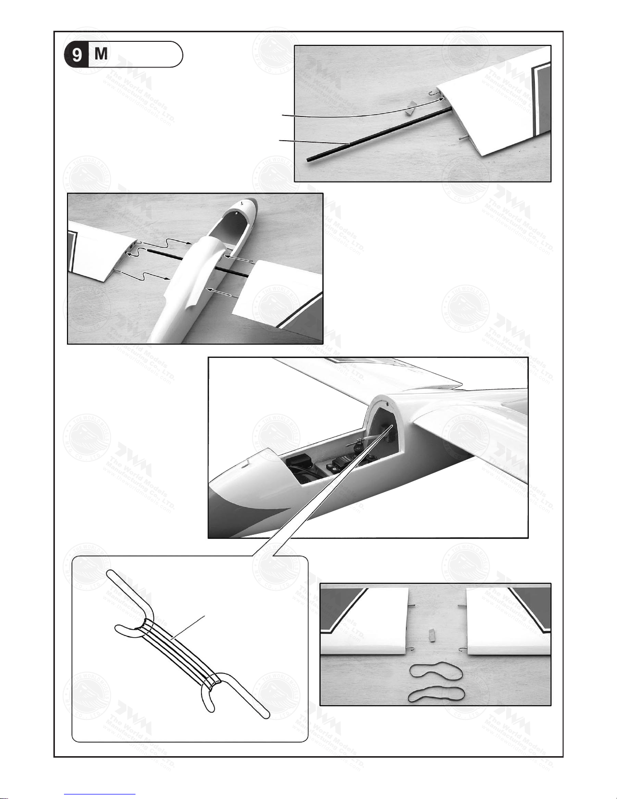
Main Wing
9
Lead to Aileron Servo
Wing Tube Dx353mm
Rudder Band
P.7
Page 9
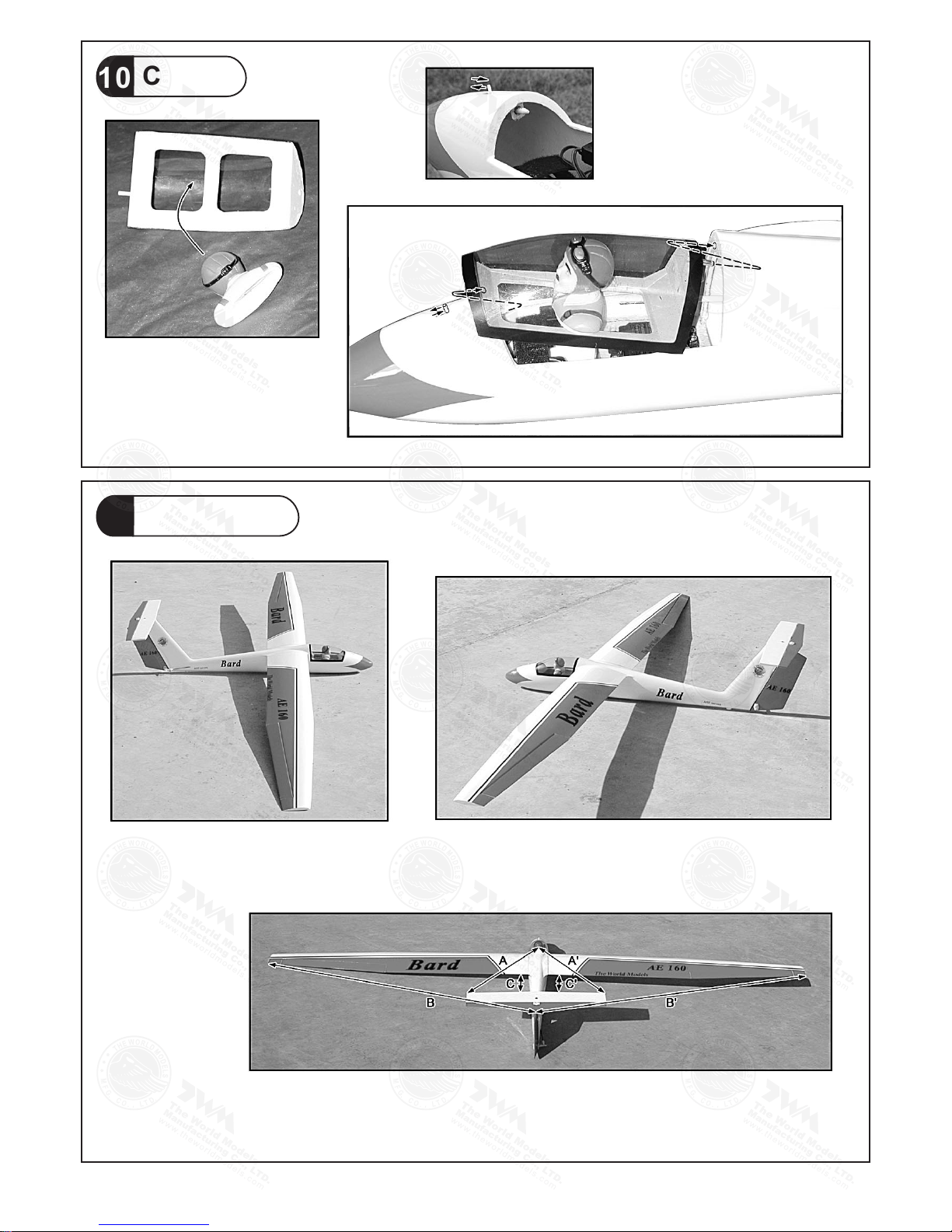
Canopy
10
Wing Setting
11
Adju st the wing and f uselage con figuratio n
as in th e diagrams.
A = A'
B = B'
C = C'
A
A'
B
B'
C
C'
P.8
Page 10
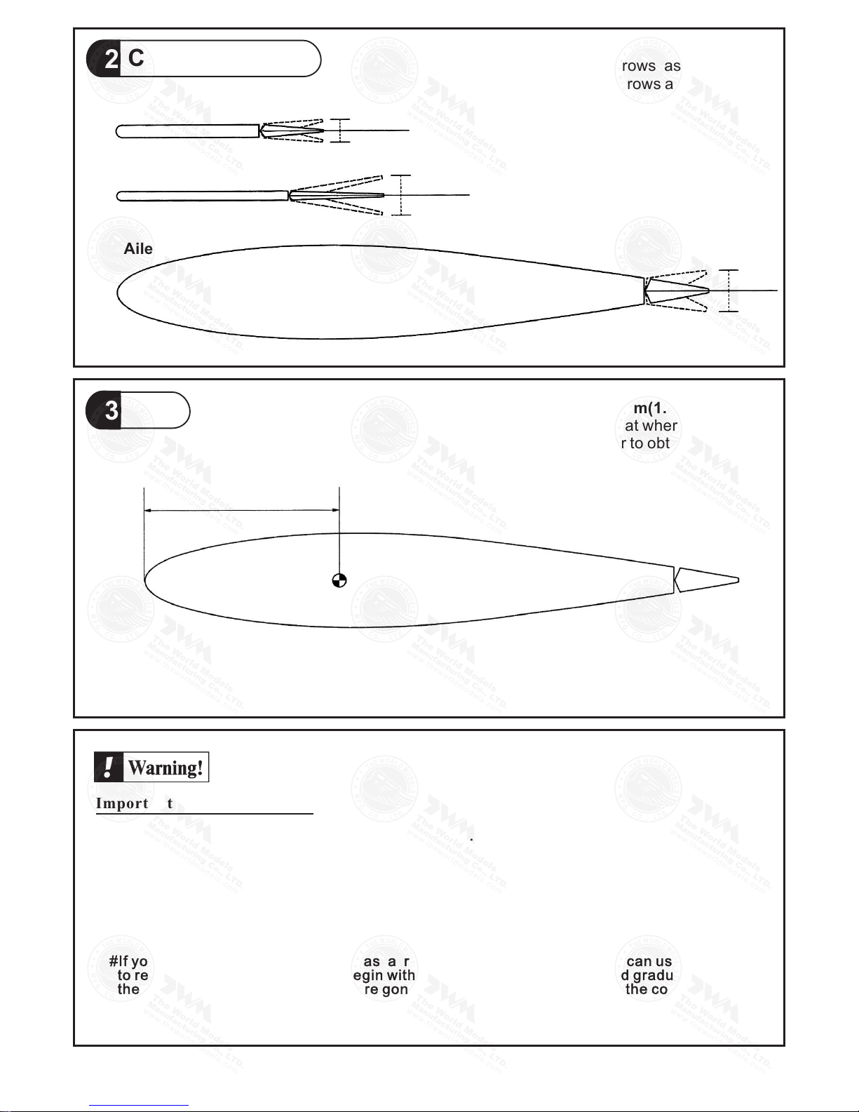
Control Throws
12
C.G.
13
Elevator
Rudder
Aileron
21mm
21mm
35mm
35mm
15mm
15mm
45mm
1.8in
C.G.
The ideal C.G. position is 45mm(1.8 in)behind
the leading edge measured at where the wing
meets the fuselage. In order to obtain the C.G.
specified, add weight to the fuselage or move
the battery position. Check the C.G. before
flying.
Adjust the control throws as shown in
the diagram. These throws are good for
general flying. You can adjust according
to your personal preference.
P.9
G160PO8300906
Important Safety Precautions
#First time flyer should never fly by h imself / herself. Assista nce from experienced fly er is
absolutely necessary.
#Pre-flight adjustment must be done before flying, it is very d angerous to fly a badly
pre-adjusted aircraft.
#Make sure the air field is spacious, n ever fly the plane too close t o people and never get
too close to a running propeller.
#If you find wrinkles on the covering a s a result of weather change s, you can use hot iron
to remove the wrinkles. Please begi n with lower temperature s etting and gradually raise
the temperature until the wrinkle s are gone. Too hot an iron m ay damage the covering.
#Check and re-tighten up all factor y assembled screws, use th read locker if applicable.
Page 11
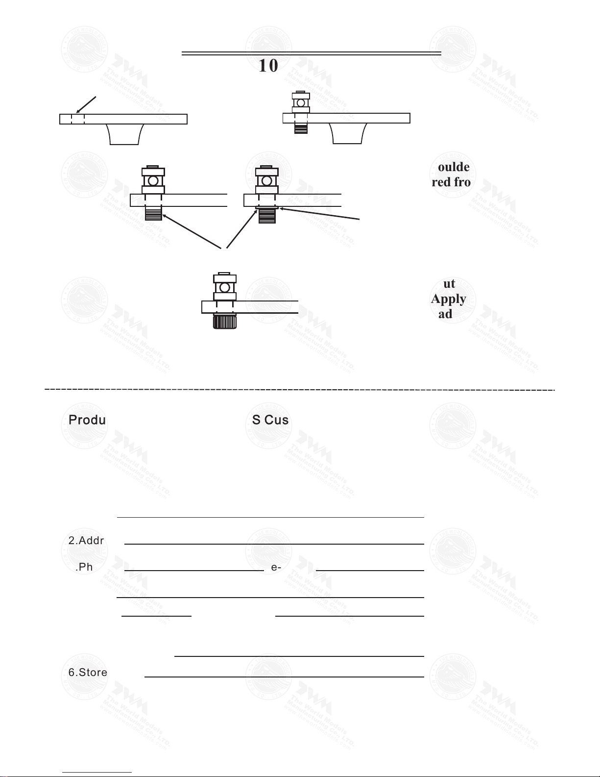
LINKAGE CONNECTOR
HW7111030 & HW7111060
Drill 2mm hole at servo horn.
Insert linkage connector
into servo horn.
Make sure shoulder of
screw is cleared from
servo horn.
Add washer to reduce
play if necessary.
Sh ou ld er
Tighten up the round nut
against the shoulder. Apply
CA or permanent thread
locker.
After fastening the round nut, make sure that
the linkage connector can rotate freely.
Product Registration Form (US Customers)
We would like to share with you any relevant information regarding your model, including
product news and free upgrade parts when applicable. Please fill in the following and send to
1.Name:
2.Address:
3.Phone #: e-mail:
4.Model:
Wing QC# Fuselage QC#
(QC numbers are stamped on wing and fuselage)
5.Date of Purchase:
6.Store Name:
Please call AirBorne Models at 925 371 0922 for any assistance in filling this form.
Thank you very much for purchasing our product.
Air Borne Models, 4749-K, Bennett Drive ,Livermore, CA 94551 USA.
 Loading...