


Warning ! This model is not a toy.
It is designed for maximum performance. Please seek advice if one is not familiar with
this kind of engine powered precision model. Operating this model without prior
preparation may cause injuries. Remember, safety is the most important thing. Always
keep this instruction manual at hand for quick reference.
* Spec if icati on s are sub je ct to cha ng e witho ut n otice .*
Specifications
INSTRUCTION MANUAL
1/3 SUPER CUB
1/3 SUPER CUB
Wing Span 141 in / 3580 mm
Wing Area 2821 sq in / 182 sq dm
Flying Weight 28.5 lbs / 13000 g
Fuselage Length 91 in / 2310 mm
Requires: 80 c.c. gasoline engine,
5-channel radio w/ 8 high
torque servos
.
E
A
D
R
-
Y
T
-
T
S
O
O
-
F
M
L
L
Y
A
FACTORY PRE-FABRICATED
ALMOST-READY-TO-FLY (ARF) SERIES
MADE IN CHINA
Manufacturing Co.,Ltd.
A186SRPO248 010 09
P. 3-12
Check all parts. If you find any defective or missing parts contact your local dealer. Please DRY FIT
and check for defects for all parts that will require CA or Epoxy for final assembly. Any parts you
find to be defective after the gluing process may be difficult to remove for warranty replacement. The
manufacturer will replace any defective parts, but will
not
extend to the parts that are good before
gluing to defective parts during assembly. Warranty will not cover any parts modified by customer.
INDEX
BEFORE YOU BEGIN
PARTS LIST
ASSEMBLY
SAFETY PRECAUTIONS
P. 1
P. 2
P.12
BEFORE YOU BEGIN
Read through the manual before you begin, so you will have an overall idea of what to do.
Symbols used throughout this instruction manual comprise of the following : -
1
2
3
1/3 SUPER CUB
1/3 SUPER CUB
3mm
Do not overlook this symbol!
Cut off shaded portion.
Peel off shaded portion
covering film.
Pay close attention here!
Pierce the shaded portion
covering film.
Must be purchased separately!
Drill holes with the specified
diameter (here: 3mm).
Ensure smooth non-binding
movement while assembling.
Apply instant glue
(C.A. glue, super glue.)
Assemble left and right
sides the same way.
Apply epoxy glue.
Apply thread locker
Warning!
P.1
A186SRPO248 010 09
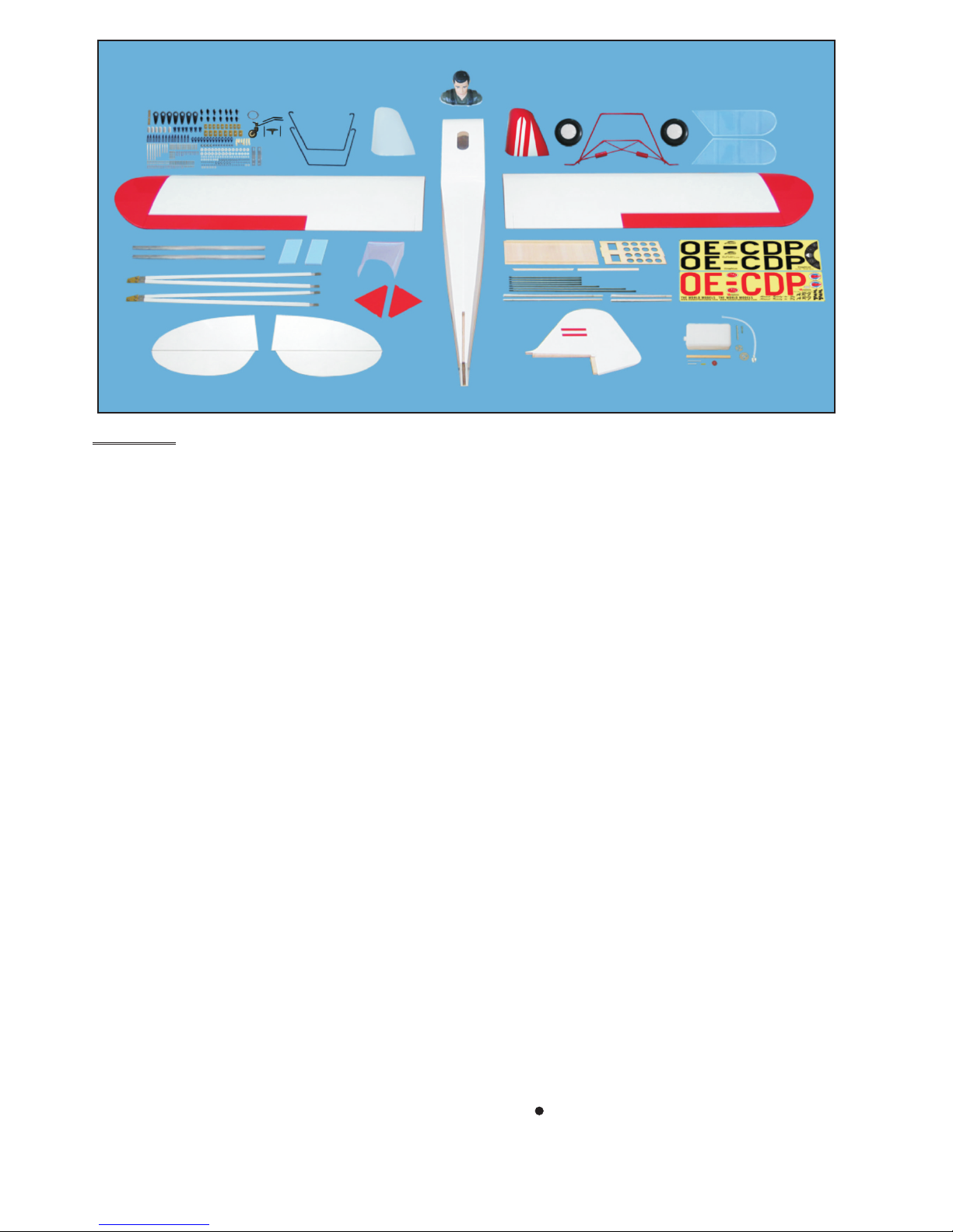
Parts List
COVE RING:
TOUGHL ON ST L 10 0 WHITE
TOUGHL ON ST L 31 2 BRIGH T RED
1. MAIN WING -- 1 pair
2. SERVO MOUNTING PANEL (For Aileron) -- 2 pairs
HEAVY DUTY CLEVIS PL4112200 -- 8 sets
SCREW PM4x60mm -- 4 pcs
SCREW PWA2.3x8mm -- 16 pcs
M4 NYLON INSERT LOCK NUT -- 4 pcs
HEAVY DUTY HORN BRACKET PL4112400 -- 4 sets
HEAVY DUTY SERVO HORN PL4120300 -- 4 sets
PUSHROD Ø2.3x129mm w/ Threads (For Aileron) -- 2 pcs
PUSHROD Ø2.3x108mm w/ Threads (For Flap Servo) -- 2 pcs
SWIVEL CLEVIS HORN FAIRING PL4610010 -- 4 sets
3. SCREW HM4x20mm -- 12 pcs
COPPER CLIPPER 0.5mm -- 8 pcs
MAIN WING STRUTS -- 1 pair
WING STRUT WIRE D4mm -- 2 pcs
M4 NYLON INSERT LOCK NUT -- 4 pcs
WASHER d4xD9mm -- 4 pcs
WASHER d4xD12mm -- 4 pcs
4. FUSELAGE -- 1 pc.
STABILIZER & ELEVATOR -- 1 set
SCREW PWM2.5x12mm -- 2 pcs
STABILIZER WIRE Ø4x200mm -- 2 pcs
5. VERTICAL FIN & RUDDER -- 1 set
6. TAIL GEAR ASSEMBLY (PL3410022) --1 set
COPPER PLATE (For Stays on Tail Fueslage Bottom) 1x12x60mm -- 1 pc.
SCREW PA3x18mm -- 3 pcs
SCREW PWA2.5x12mm -- 2 pcs
7. MAIN LANDING GEAR -- 1 set
SCREW HM4x18mm -- 2 pcs
SCREW PA3x14mm -- 12 pcs
SCREW PA4x20mm -- 2 pcs
WASHER d4xD12mm -- 2 pcs
WASHER d4xD9mm -- 2 pcs
MOUNTING PLATE 12x20mm -- 6 pcs
ALUMINUM PLATE 3x15x77mm -- 2 pcs
8. SCREW PA1.7x8mm -- 6 pcs
SCREW PM3x10mm -- 8 pcs
WASHER d3xD7mm -- 16 pcs
M3 NUT -- 8 pcs
COLLAR Ø6.1mm w/ set screw -- 4 sets
LARGE SCALE CAPTIVE AIR WHEELS Ø140mm(PL3115140) -- 2 sets
PLYWOOD 2x211.5x193.5mm (Main Langing Gear Cover) --1 pair
COPPER CLIPPER 0.5x12x20mm -- 8 pcs
9. BLIND NUT M6 -- 4 pcs
WASHER d6xD15mm -- 4 pcs
SOCKET HEAD SCREW M6x30mm -- 4 pcs
10. COWLING -- 1 pc.
TRANSPARENT 3D TEMPLATE -- 1 pc.
SCREW PA3x12mm -- 4 pcs
WASHER d3xD7mm -- 4 pcs
SILICON GROMMET d2.5xD8.5mm -- 4 pcs
11. FUEL TANK 1500cc (PL1121500G-gasoline) -- 1 set
CABLE TIE (For Fuel Tank) 1.5x8x500mm -- 1 pc.
DOUBLE-SIDED TAPE 40x160mm -- 1 pc.
12. PUSHROD Ø2.3x215mm w/ Threads (For Elevator) -- 2 pcs
SCREW PM4x50mm -- 2 pcs
M4 NYLON INSERT LOCK NUT -- 2 pcs
SWIVEL CLEVIS HORN FAIRING PL4610010 -- 2 sets
HEAVY DUTY HORN BRACKET PL4112400 -- 2 sets
HEAVY DUTY SERVO HORN PL4120250 -- 2 sets
HEAVY DUTY CLEVIS PL4112200 -- 4 sets
13. PUSHROD Ø2.3x170mm w/ Threads (For Rudder) -- 1 pc.
SCREW PM4x50mm -- 1 pc.
M4 NYLON INSERT LOCK NUT -- 1 pc.
SWIVEL CLEVIS HORN FAIRING PL4610010 -- 1 set
HEAVY DUTY HORN BRACKET PL4112400 -- 1 set
HEAVY DUTY SERVO HORN PL4120250 -- 1 set
HEAVY DUTY CLEVIS PL4112200 -- 2 sets
14. SCREW PM2x18mm -- 12 pcs
WASHER d2xD5mm -- 24 pcs
M2 NUT -- 12 pcs
CLEVIS -- 12 pcs
WIRE Ø1x4200mm -- 1 pc.
FLYING WIRE BRACKET -- 12 pcs
CLIP PIN -- 12 pcs
EYE SCREW -- 6 pcs
COPPER TUBE d2.5xD3.2x8mm (For Rudder) -- 16 pcs
15. SIDE WINDOWS -- 1 pair
16. LINKAGE CONNECTOR Ø2.1mm w/ set screw -- 1 set
17. PLYWOOD 3x196x304mm (For Fuselage Servos) -- 1 pc.
PLYWOOD 3x10x160mm (For Fuselage Servo Stand) -- 2 pcs
BALSA 10x10x288mm (For Fuselage Servo Stand) -- 2 pcs
SPONGE 10x80x200mm -- 2 pcs
THROTTLE PUSHWIRE Ø1.2x480mm -- 1 pc.
PLASTIC TUBE d2xD3xd300mm -- 1 pc.
18. PILOT PC101110A -- 1 set
SCREW PWA2x12mm -- 4 pcs
COCKPIT BASE PANEL 3x196x444mm -- 1 pc.
WOOD 10x10x443mm (For Cockpit Base Panel) -- 2 pcs
19. WIND SHIELD -- 1 pc.
M2 NYLON INSERT LOCK NUT -- 2 pcs
SCREW PM2x14mm -- 2 pcs
WASHER d2xD5mm -- 4 pcs
MOUNTING PLATE 5x15mm -- 2 pcs
BALSA ROD Ø8x220 -- 2 pcs
20. WING TUBE Ø22x931mm -- 2 pcs
SCREW HM3x30mm -- 2 pcs
SCREW PA3x30mm -- 2 pcs
WASHER d3xD7mm -- 4 pcs
21. SCREW HM4x15mm -- 2 pcs
WASHER d4xD12mm -- 2 pcs
M4 NYLON INSERT LOCK NUT -- 2 pcs
22. DECALS: A186SRDEC -- 1 set
P.2
A186SRPO248 010 09
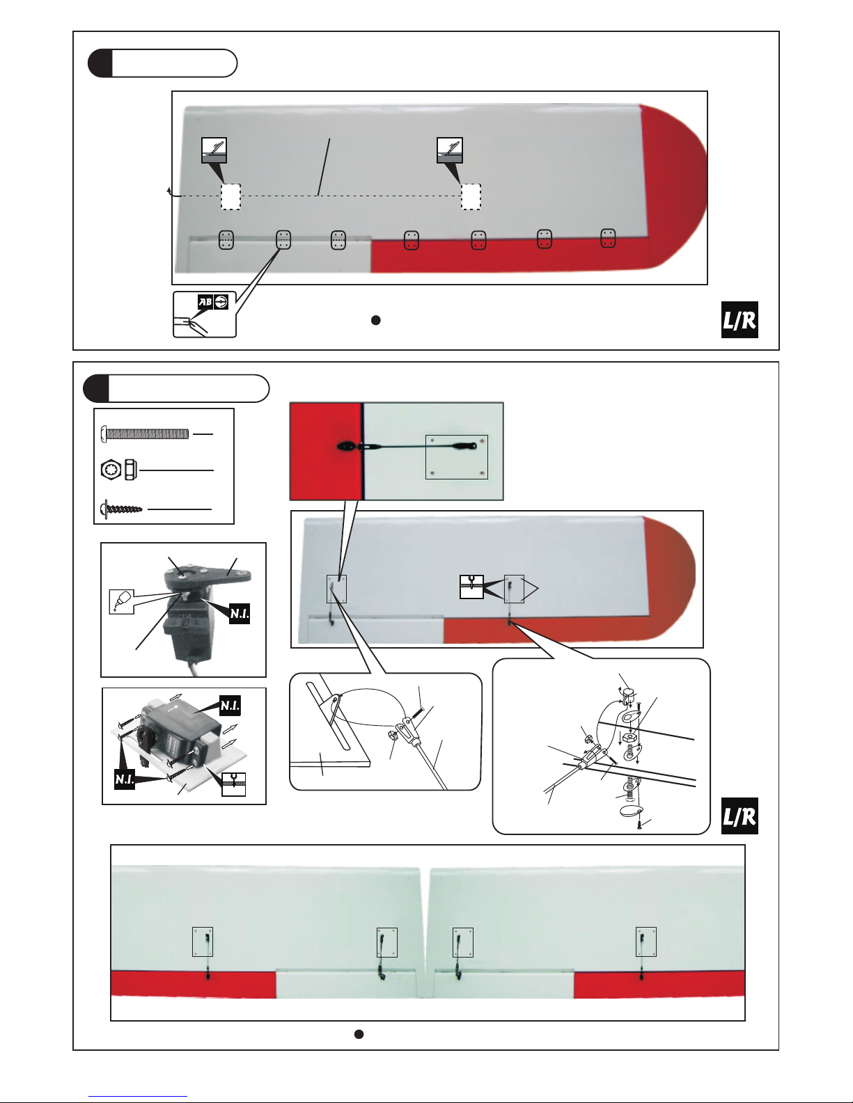
2
Aileron & Flap servo
1
Main Wing
Pre -glue d
PM4x 60 mm Scre w
M4 N YL ON I NS E RT LO C K NU T
4
4
Aile ron & Flap Ser vo Lead
Bottom View
Bottom View
16
PWA2.3 x 8mm Screw
PWA 2.3 x 8mm
M2
x
10
mm
H
e
a
vy Du t
y
Cl
evi s
SER VO M OUN TI NG PAN EL
M2 NY LON
INS ERT LOC K NUT
Pushrod
Ø2. 3x108 mm
SER VO MOUN TING PANE L
1mm
1.5mm
Pushrod
Ø2.3x12 9m m
PM4 x 60m m
M4 Nyl on I nsert
Lock N ut
PM2x10m m
Heavy Duty
Clevis
Heav y Du ty H or n
Bracke t
PA1. 7x 8mm
M2 Nyl on I nsert
Lock N ut
M2 NUT
M2x8mm
PL4120300
P.3
A186SRPO248 010 09

Stabilizer & Elevator
COMPLETE D
5
Vertical Fin & Rudder
COMPLETED
Pre-g lu ed
(St abili zer)
(Ma in Wing )
B B'
B=B'
HM4x20mm
Washer d4xD9mm
3.5mm
HM4 x 20mm
M4 Nylon Insert Lock Nut
Main Wing Strut
d4xD 12mm Wash er
HM4x20mm Screw
12
4
d4xD 9mm Washe r
4
4
M4 N YLON I N SE R T LOCK N UT
3
4
Bottom View
Tempor a r y i nstall t h e main w i n g , adjust
leveling o f the s t a b i l i z e r to m a k e it a s
parallel t o the m a i n wing a s possible.
Wing Struts
465 mm 481 mm
174 mm
280 mm
184 mm
260 mm
d4xD12 mm
Was he r
Pre -glue d
P M mm W 2.5x12 Screw
2
P M mm W 2.5x12
Ø4x200mm
P.4
A186SRPO248 010 09
Bottom View
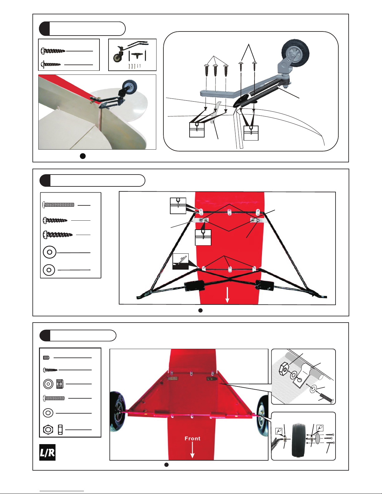
Tail Landing Gear
6
8
Landing Gear
PA1. 7x 8m m
Collar
M3x3mm
Set Screw
M3x3mm
Set Screw
Collar
PM3x10mm Screw
PA1.7X8mm Screw
d3xD7mm Washer
M3 Nut
8
6
16
8
4
3mmSet Screw
4
6.1mm Collar
d4xD12mm Washer
HM4x18mm S cre w
2
2
PA3x14mm S cre w
12
d4xD9mm Washer
2
PA4x20mm S cre w
2
Bottom View
Bottom View
PM3 x10mm
d3x D7mm
Was her
Coppe r Plate
0.5 x12x2 0mm
M3 Nut
7
Main Landing Gear
Fron t
PA3x14mm
PA4x20mm
HM4x 18 mm
d4xD 9m m
Was he r
d4xD 12 mm
Was he r
Alum inum Pla te
3x15 x7 7mm
1.5mm
2.5mm
P.5
3
2
PWA2.5 x 12mm
PA3 x18mm
Copper Plate
1x12x60mm
Spring
2.5mm
1.5mm
Bottom View
PA3x18mm Screw
PWA2.5x12mm Screw
A186SRPO248 010 09

Engine
9
d6xD15mm Washer
M6 Blind Nut
4
4
4
M6x30mm Socket Head Screw
Cowling
10
PA3x1 2mm S crew
d2.5 x8.5mm Sil icon Gr ommet
4
4
207mm
8.15 in.
COMPLETED
First i nsert the grom met to the cowli ng then apply sc rew.
Plea se re fer to th e attac hed
shee t for usage of t he
tran sparent 3D t empla te.
Was he r
d6xD 15 mm
M6 Bli nd N ut
Socket Head Screw
M6x30mm
7.5mm
1.5mm
d3xD7mm Washer
4
P.6
Cowling
Fuselage
d2.5x8.5mm
Silicon Grommet
PA3x12mm
d3xD7mm
A186SRPO248 010 09

Rudder
Pushrod
Elevator Pushrod
Fuel Tank
11
Bottom View
Bottom View
13
12
P.7
PM4x 50mm Screw
2
2
Elevator Pushrod
PM4x5 0m m
M4 Nylon In se rt L oc k Nu t
M2 Nylon In se rt L oc k Nu t
M2x10 mm
Heavy Dut y Cl ev is
Heavy Dut y Ho rn B ra ck et
PA1. 7 x8 mm
M4 Nylon Insert Lock Nut
M2 Nut
M2x8mm
PL41202 50
Hea vy Duty H orn
Bra cket
M2 Nylo n In sr t
Lock Nu t
Heavy Duty
Clevis
PM4x50mm
M2x 10mm
M4 Nylon Insert
Lock Nut
PA1. 7 x8 mm
Pus hrod
PM4x 50mm Screw
1
1
M4 Nylon Insert Lock Nut
M2 Nut
M2x8mm
PL41202 50
Fuel Tank
1500cc
Completed
UP
CABLE TIE
1.5x8x500mm
DOUBLE-SIDED
40x160mm
1 2 3
A186SRPO248 010 09

Servo Set
16
14
Flying Wire
Windows
Securely glue the windows to the fuselage.
COMPL ETED
Window A
Wind ow B
15
COMPLETED
1
1
3x3mm Set Screw
Linkage Connector
M2 Nut
2mm Washer
1
2
Please refer to t he a ttached sheet for linkage c onn ector installation.
T
h
rott
l
e Pu
s
hw
ir
e
3x3m m Set S crew
Throttle Servo.
2m m
2mm
Washer
M2 Nut
2mm
Washer
P.8
PM2x18mm Screw
12
12
d2xD5mm Washer
24
M2
PM2x18mm
PM2x18mm
d2.5xD3.2x8mm
3mm
3mm
d2xD5mm
Washer
M2 N UT
Cop per Tub e
Pre ss down t he cent er
1/ 3 po rtion
A186SRPO248 010 09
M2 Nut

18
Pilot
Wind Shield
19
PWA 2x 12mm Screw
M2 NYLON INSERT LOCK NUT
2
PM2x 14mm Screw
2
d2xD5mm Washer
4
17
Radio Equipment
lnstall and a rrange the servos as shown in the diagra m.
PC10 11 10 A
PWA 2x 12mm Screw
Bottom View
M2 NYLON INSERT LOCK NUT
PM2 x14mm
d2x D5mm
Was her
Bals a Rod
Ø8X2 20mm
Thro ttl e Servo
Spong e
Receive r
Thro tt le P us hrod
D1.2x480mm
Plas ti c Tube
d2xD 3x 30 0mm
Battery
Char ge R ec ep tacles
KP00 41 30 0
P.9
A186SRPO248 010 09
Appl y thick CA or
Cano py glue.

Main Wing
20
d3xD 7mm Washe r
2
4
PA3x30m m Scr ew
2
Step 1. Insert the aluminum wing tube with the pre-drilled hole end into the right wing. Align
the lines marked at the wing root and wing tube and apply the PM3 x 30mm machine screw
through the pre-drilled hole on top of the wing. ( please confirm the alignment of the hole by
putting a 2.5mm diameter rod through the pre-drilled wing hole before applying the screw )
The hole on the wing tube is pre-threaded, do not over tighten the PM3mm screw, the set up is for
future removal of the wing.
Step 2. Install the right wing to the fuselage by inserting the wing tube (now attached to
the right wing) through the fuselage, then install the left wing.
Step 3. Make sure the wings are resting against the fuselage tightly. Locate the pre-drilled 2.5mm
hole at top of left wing, and drill along with 2.5mm drill bit until it passes through the wing tube.
Apply the PA3 X30mm self-tapping screw.
Note : It is recommended that the wing tube stays with the left wing. Removal of the wings could
be acheived by removing the right wing machine screw, the right wing then the left wing with
wing tube. If removal of wing tube from left wing is also required, it is recommended that
instead of applying self-tapping screw in step 3, you pre-tap with M3 thread cutter and apply M3
machine screw.
Top Vi ew
Right
Left
PA 3x30mm
d3xD7mm
Wing Tube
D22x931mm
345m m
345m m
70mm
185m m
HM 3x3 0m m
d3xD 7mm
2.5mm
2.5mm
P.10
HM3x 30mm Screw
A186SRPO248 010 09

Wing Setting
Adjust the w ing a nd fuselage confi gur ation as shown
in the diagr ams .
Wing Struts
d4xD 12mm Wash er
2
2
M4 N YLON I N SE R T LOCK N UT
2
B'
C'
B
C
21
22
A
A'
HM4x 15 mm
Wash er
d4 xD1 2m m
M4 N YLON I N SE R T LOCK N UT
P.11
HM4x 15mm Screw
A186SRPO248 010 09

23
Control Throws
Adjust the control throws as shown in
the diagram. These throws are good for
general flying. You can adjust according
to your personal preference.
Ailerons(away from fuse lag e)
40mm
Elevator
50mm
Rudder
65mm
24
C.G.
The ideal C.G. position is 150mm (5.9 in ) behind the leading edge measured at where
the wing meets the fuselage. In order to obtain the C.G.specified, add weight to the
fuselage or move the battery position. Check the C.G. before flying.
.
65mm
50mm
40mm
15
0 m
m
5
.
9
i
n
.
F
la
ps (
n
e
ar f
us
ela
g
e)
60mm
C.G.
Important Safety Precautions
9
Warning!
# First t i me flye r s h ould n e v er fly by h i m self / h e r self. Assist a n ce from e x perie n c ed
flyer i s a bsolu t e ly nece s sary.
# Pre-f l i ght ad j u stmen t m u st be do n e b efore f l ying, i t i s v ery da n g erous t o f l y a badl y
pre-a d juste d a i rcraf t .
# is spec i a lly de s i gned to b e p owere d b y 8 0C.C . gasol i n e e ngine , u s ing
a more powerf u l e ngine d o e s not me a n b etter p e rform a n ce. In fa c t , over p o w ered
engin e m ay caus e s e vere d a m age and i n j urie s .
# Make su r e the air f i e ld is sp a c ious, n e v er fly t h e p lane to o c lose to p e o ple an d n e ver
get too c l ose to a ru n n ing pr o p eller.
# If you f i n d wrink l e s on the c o v ering a s a r esult o f w e ather c h anges , y o u can us e h o t
iron to r e move th e w r inkle s . Pleas e b e gin wi t h l ower te m p eratu r e setti n g a nd
gradu a l ly rai s e the te m p eratu r e until t h e w rinkl e s are gon e . Too ho t a n i ron ma y
damag e t he cove r i ng. Don ' t u se hot i r o n near t h e s eams or e d ges, ho t i r on will
melt th e g lue and s h r ink th e c o verin g a t t he sam e t i me, cau s ing the s e a ms to pu l l a way.
# Check a n d re-ti g h ten up a l l f actor y a s semb l e d screw s , u se thr e a d locke r i f n eces s a ry.
1/3 S UPER C UB
P.12
A186SRPO248 010 09

A186SRPO248 010 09
Product Registration Form (US Customers)
We would like to share with you any relevant information regarding your model, including
product news and free upgrade parts when applicable. Please fill in the following and send to
AirBorne Models, 4749-K, Bennett Drive, Livermore, CA 94551 USA.
1. Name:
2. Address:
3. Phone #: E-mail:
4. Model:
Wing QC# Fuselage QC#
(QC numbers are stamped on wing and fuselage)
5. Date of Purchase:
6. Store Name:
Please call AirBorne Models at 925 371 0922 for any assistance in filling this form.
Thank you very much for purchasing our product.
LINKAGE CONNECTOR
HW7111050 & HW7111060
After fastening the round nut, make sure that
the linkage connector can rotate freely.
Drill 2mm hole at servo horn.
Insert linkage connector
into servo horn.
Make sure shoulder of
screw is cleared from
servo horn.
Add washer to reduce
play if necessary.
Shoulder
Tighten up the round nut
against the shoulder. Apply
CA or permanent thread
locker.

1
3
4
2
Usage of the transparent 3D template
This transparent 3D template
is used for position guidance
of the actual cutting of the
pre-painted cowling.
Simply cut the transparent 3D template to fit your engine and
exhaust pipe, then slide onto the actual cowling and use as
template to mark the openings required for final cutting.
A186SRPO248 010 09

KP0041300
Special tool fo r cle vis installation.
Suitable for st and ard and small
(EP) c lev is.
Larg e Cl ev is
Smal l Cl ev is
Optional Parts
ACCESSORIES
180mm Y Cord
KW0011800 180mm 1 set
180mm Extension
KW0021800 180mm 1 pc
Charge Receptacles
Field Stand
MS9111450 600X240X350mm 1pc
Code N o. Size
Pack ag e
Code N o. Size
Pack ag e
Code N o. Size
Pack ag e
Code N o. Size
Pack ag e
Clevis Wrench
Code N o. Size
Pack ag e
PL8210010 1 set
A186SRPO248 010 09

The World Models
Manufacturing Co., Ltd.
www.the w orl d m o d e l s . c o m
Warbirds
Scale
Sports
Trainer
Ducted Fan
Pattern
Funfly
Electric
Glider
Boat
Accessories
Covering
(Lightex / Toughlon)
A186SRPO248 010 09
 Loading...