

Page 1
TWK-ELEKTRONIK GmbH D-40041 Düsseldorf Tel. +49 211 96117-0 info@twk.de
Heinrichstrasse 85
User Manual PMU - 04
Date: 04.03.2015
Document No.: PMU 13375 AE
User Manual
PMU - 04
P.O. Box 10 50 63 Fax +49 211 637705 www.twk.de
Page 2

User Manual PMU - 04
Date: 04.03.2015
Document No.: PMU 13375 AE
Page 2 of 15
protected by copyright laws and international treaty provisions.
COPYRIGHT: The PMU 13375 operating instructions
are owned by TWK-ELEKTRONIK GMBH and are
© 2015 by TWK-ELEKTRONIK GMBH
POB 10 50 63 ■ 40041 Düsseldorf ■ Germany
Tel. +49/211/63 20 67 ■ Fax +49/211/63 77 05
info@twk.de ■ www.twk.de
Page 3

User Manual PMU - 04
Date: 04.03.2015
Document No.: PMU 13375 AE
Page 3 of 15
1 Safety instructions ___________________________________________________ 4
2 General information __________________________________________________ 5
3 Connection of the programmer PMU - 04 _________________________________ 5
3.1 Software installation _____________________________________________________ 5
3.2 Initial commissioning of PMU - 04 __________________________________________ 6
4 Execution of the programme PMU - 04 __________________________________ 11
5 Software and hardware versions _______________________________________ 14
6 Literature __________________________________________________________ 15
Page 4

User Manual PMU - 04
Date: 04.03.2015
Document No.: PMU 13375 AE
Page 4 of 15
1 Safety instructions
Scope
This user manual applies exclusively to the Universal Programmer PMU – 04.
Documentation
The following documents must be observed:
- The owner's system-specific operating instructions and general regulations of
ZVEI
- User manual for Universal Programmer PMU: PMU13375
- Rotary encoder data sheets for CRF/SRF: CRF10266 and for DAF/SAF: DAF10286
(The SRF and SAF versions stand for the stainless steel versions and are electrically fully compatible with the
basic versions CRF and DAF)
- The connection diagrams TYxxxx enclosed with the devices
Proper use
The TWK-ELEKTRONIK GmbH angle and linear transducers are used to register angle or
travel positions and provide their measured value as an electrical output signal. As part of a
system, they must be connected to the downstream electronics and must only be used for
this purpose.
Commissioning
• ... The devices must only be commissioned and operated by a specialist electrician.
• ... The rotary encoder is installed and removed in de-energised condition.
• ... The devices must be protected against mechanical and electrical damage during
installation and operation.
• ... The devices must not be operated outside of the specified values.
• ... All electrical connections must be tested before commissioning the system.
Page 5

User Manual PMU - 04
Date: 04.03.2015
Document No.: PMU 13375 AE
Page 5 of 15
2 General information
The data sheet for the programmer PMU – PMU12005DE0 /1/ forms the basis for the user manual.
The programmer PMU - 04 has been extended with the active control mode functionality for the CRF/SRF /2/
and DAF/SAF /3/ rotary encoders. As well as the option of programming the rotary encoder according to
customer-specific requirements, the user now also has the option of viewing and checking the programmed
values in control mode. This option makes it easier to check the values programmed for the rotary encoders
with separate operation of the programmer or when the control system is connected.
As part of this extension, the following limitations have been implemented in comparison with the predecessor
version.
1. General changes:
- The up/down mode is not represented in control mode. The function is carried out exclusively
using the rotary encoder's multifunction pins.
- The offset value is defined from 0 to 16,777,215 and not as ± 32,768 as before.
2. Rotary encoder-specific changes with reference to the interface:
- CRF/SRF – SSI: The monoflop time can only be changed in the factory.
The example application descriptions contained in this user manual refer to Windows 8.1.
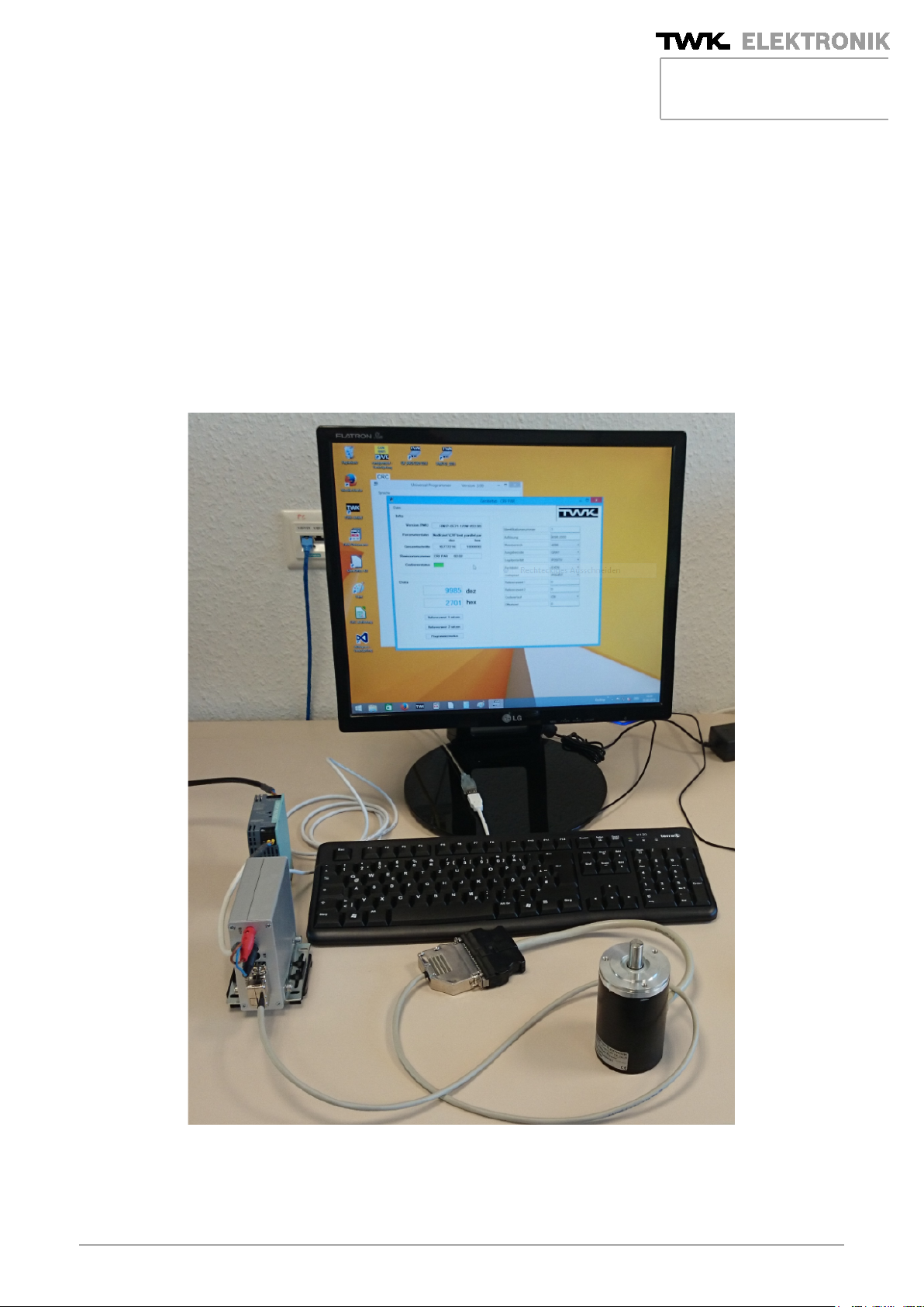
3 Connection of the programmer PMU - 04
Commissioning of the PMU-04 is carried out in the following steps:
1. Connection of the rotary encoder to the front side of the PMU-04 using the 15-pin SUB-D connector
(connection cable corresponding to rotary encoder version /1/ )
2. Connection of the USB cable – USB connector type B on the programmer and USB connector type A
on the PC (operating system: Windows 7, 8, 8.1)
3. Programmer supply via USB or power supply unit (24 V/1 A) using 4 mm laboratory sockets or power
supply unit connector (NE S/J 21)
The connection of a rotary encoder is necessary in each case to be able to work with the programmer.
Communication between the PC, programmer and rotary encoder takes place continuously. If this
communication is disturbed, an error message to the effect that the programmer is not detected is output. The
problem must be eliminated by the user. The programmer function can only be used when connected correctly.
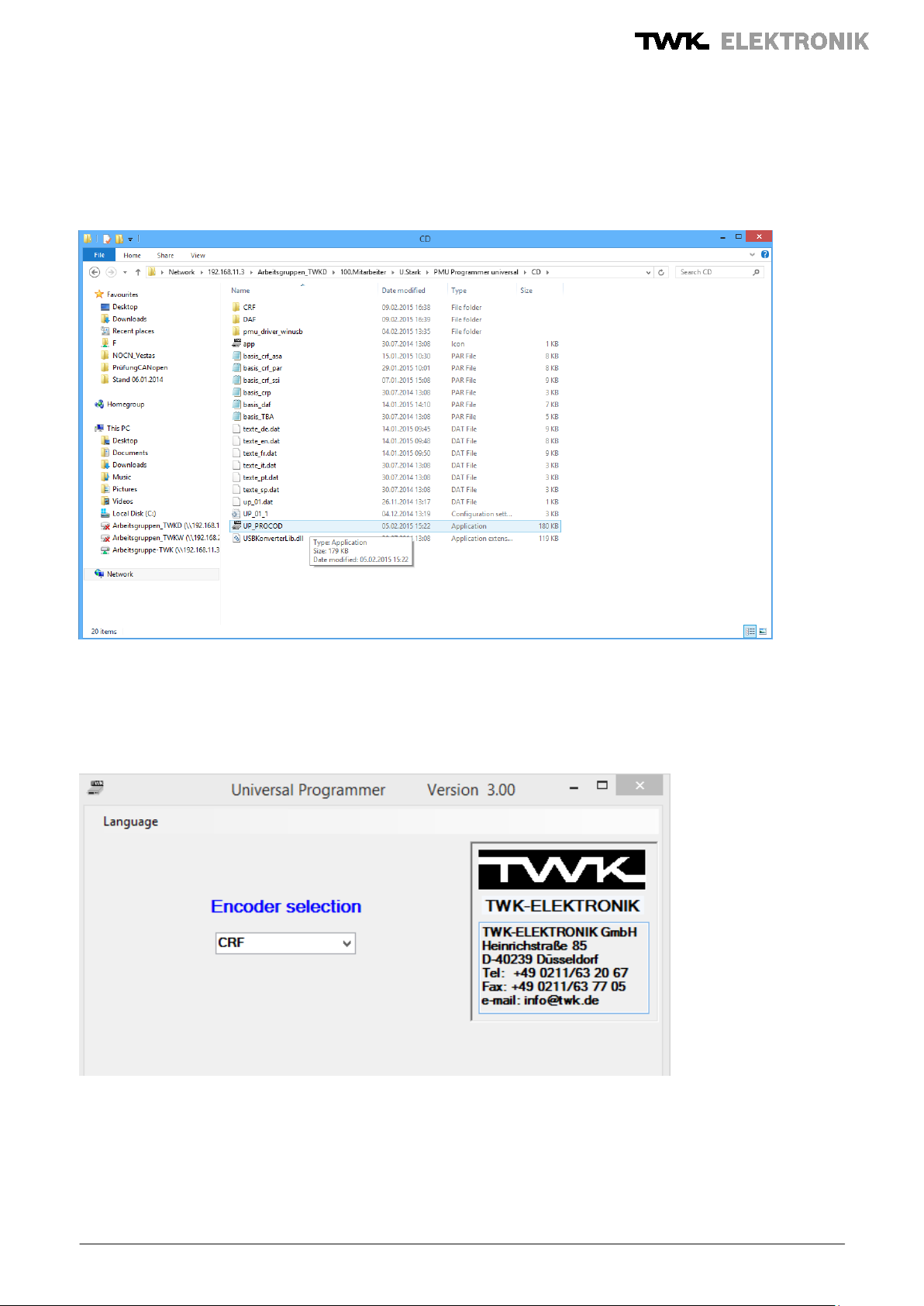
3.1 Software installation
The CD enclosed with the PMU contains the files required to execute the program PMU-04 (option: software
transmission by E-mail). The customer must save these to a separate directory on its computer, also see
Figure 1. The CRF and DAF directories are intended for saving the application-specific parameter files. The
pmu_driver_winusb directory contains the drivers for the programmer PMU – 04; if the programmer is not
detected automatically, these can be integrated manually, also see point 3.2. The application is the programme
UP_PROCOD.exe. It must be remembered that all files must be loaded into the desired target directory.
Page 6

User Manual PMU - 04
Date: 04.03.2015
Document No.: PMU 13375 AE
Page 6 of 15
Figure 1: Universal Programmer PMU – 04 software scope
3.2 Initial commissioning of PMU - 04
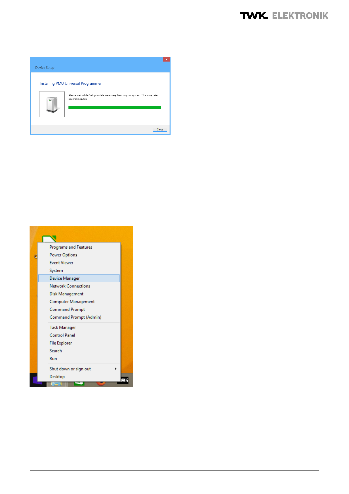
The programmer PMU - 04 is connected to the PC by means of the enclosed USB cable. On automatic
detection of the programmer, the following message is output:
Figure 2: Programmer PMU – 04 is being installed
The window must be closed following successful installation, see Figure 3.
Page 7
User Manual PMU - 04
Date: 04.03.2015
Document No.: PMU 13375 AE
Page 7 of 15
Figure 3: Close window following successful installation.
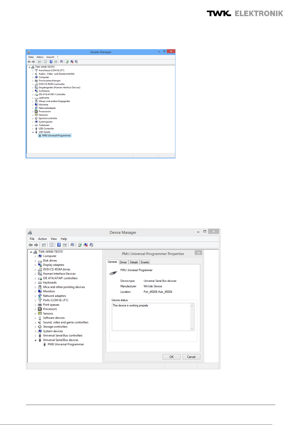
If the Windows device driver is automatically found and installed, you are subsequently notified that the device
is ready for use. On successful driver installation, the PMU Universal Programmer is displayed in the device
manager (Figure 5).
The properties of the newly installed USB device can be called up via the device manager, which can be
started by clicking with the right mouse button onto the Start button (Figure 4).
Following successful installation of the programmer, the application can be started, see point 3 of the user
manual.
Figure 4: Access to the device manager (Windows 8.1)
Page 8
User Manual PMU - 04
Date: 04.03.2015
Document No.: PMU 13375 AE
Page 8 of 15
Figure 5: PMU - 04 in the device manager
Manual installation of the PMU
If automatic installation is not to take place, please carry out the following steps:
Open the device manager and click onto the PMU Universal Programmer, which can be found under the USB
devices, see Figure 5.
The properties of the PMU Universal Programmer are displayed in the window, see Figure 6.
Figure 6: Properties of the PMU Universal Programmer
Page 9

User Manual PMU - 04
Date: 04.03.2015
Document No.: PMU 13375 AE
Page 9 of 15
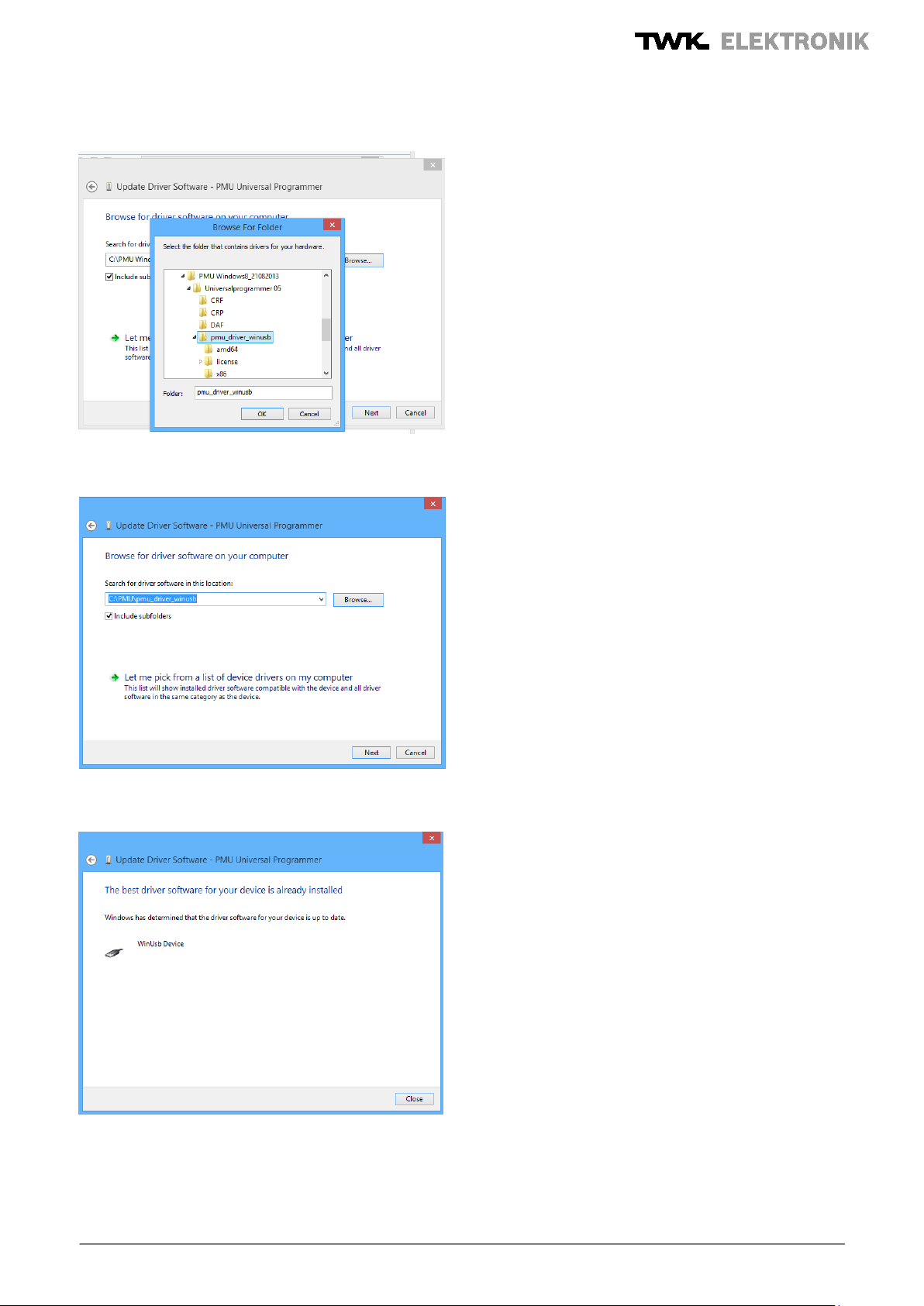
Under the driver tab, you can install or also update the drivers for the USB device PMU – 04.
The sequence is shown in Figures 7 – 11.
Figure 7: Select driver software in the directory created for the programmer PMU – 04
Figure 8: Directory for the USB drivers
Page 10
User Manual PMU - 04
Date: 04.03.2015
Document No.: PMU 13375 AE
Page 10 of 15
Figure 9: Confirmation of the directory for the drivers
Figure 10: Starting manual driver installation
Figure 11: Window after updating the drivers
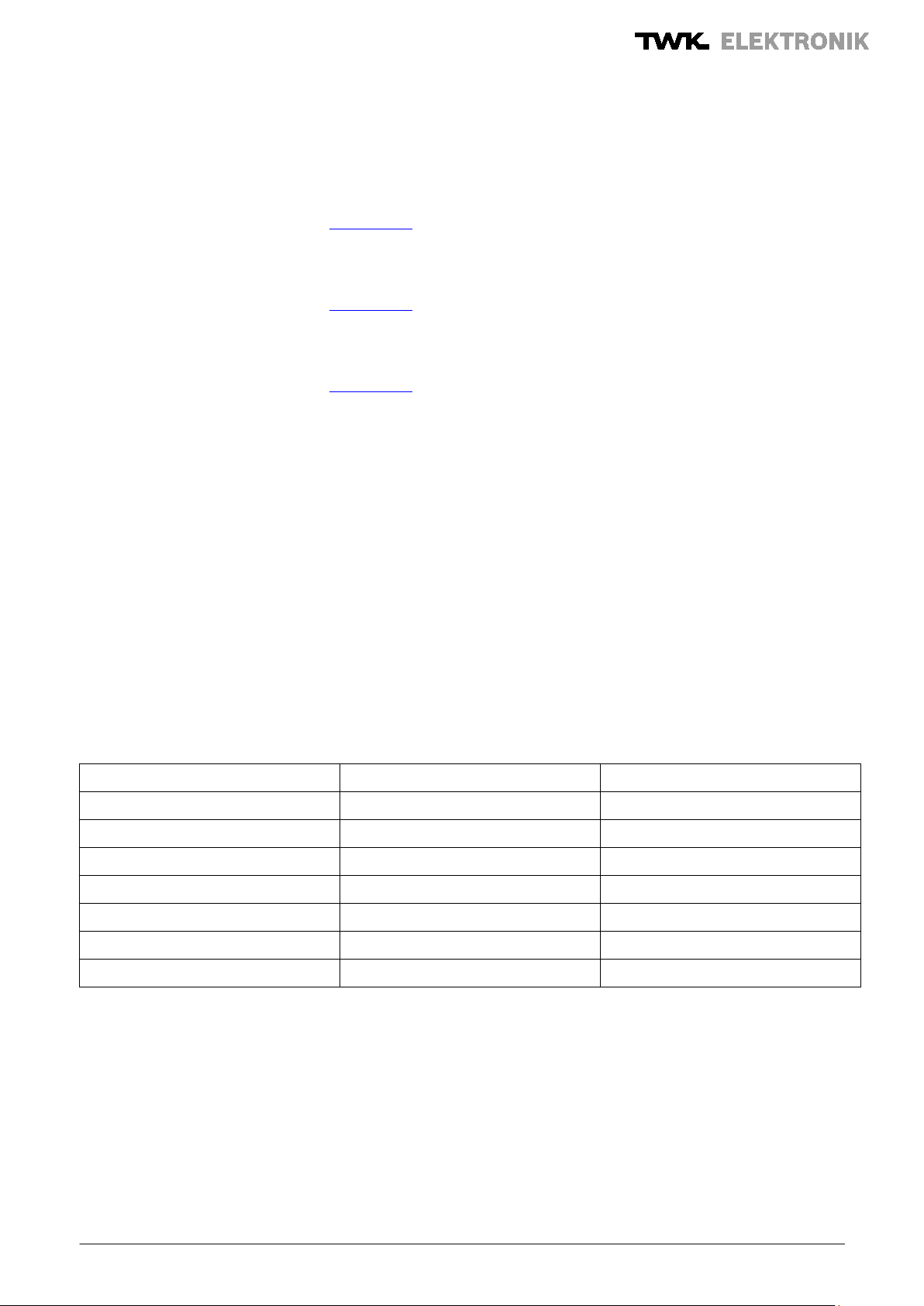
Following successful manual driver installation, you can start the application UP_PROCOD.exe. After selecting
the language and the rotary encoder type (confirm with Enter), you are routed to the main menu for
programming the rotary encoder. The following steps are described under point 4.
Page 11
User Manual PMU - 04
Date: 04.03.2015
Document No.: PMU 13375 AE
Page 11 of 15
4 Execution of the programme PMU - 04
The application file up_procod.exe for starting the programmer PMU – 04 can be found in the directory created
by the customer for the programmer PMU – 04, Figure 12.
Figure 12: Starting the programmer PMU - 04
After starting, the relevant language and the encoder type are selected (Figure 13). The relevant configuration
is confirmed with Enter.
Figure 13: Selection of the language and the encoder type
After confirming the encoder type with the Enter button, the main window is opened (Figure 14).
Page 12

User Manual PMU - 04
Date: 04.03.2015
Document No.: PMU 13375 AE
Page 12 of 15
Figure 14: Main window
In the next step, the parameter file is created (see the CRF and DAF directories planned for this), the
parameters are configured and, finally, the parameters are stored in a parameter file (Figure 15). After
restarting the programmer, the selected parameters are therefore available in a customer-specific file.
The parameter changes must each be confirmed with Enter.
Page 13

User Manual PMU - 04
Date: 04.03.2015
Document No.: PMU 13375 AE
Page 13 of 15
Figure 15: Main window with parameter file
The rotary encoder is then programmed using the Programming button. Once this process has taken place, the
green colour field again appears in the encoder status. During access, the colour field is orange. Proper
programming of the rotary encoder can be checked using the "Load parameter" function. The encoder values
are displayed in the parameter list. Basic setting is carried out via the "Default setting" button and enables you
to return to the starting point.
Incorrect entries during parameterisation are each acknowledged with an error message. The process must
then be continued with plausible values.
The active control mode (button “Encoder activate”) has been reintroduced as an additional customer feature
(Figure 16). After programming, the encoder can now be activated and the position value displayed. It is also
possible to set the reference values 1 and 2. In contrast to the predecessor product, communication takes
place via the PR+/ PR- lines and via the signal output. Active control mode can be exited again using the
"Programming mode" button.
Page 14

User Manual PMU - 04
Date: 04.03.2015
Document No.: PMU 13375 AE
Page 14 of 15
HW
P-0571-1
SW
V02.00
DAF/SAF
02.01
CRF/SRF
SSI
02.02
Parallel
02.02
ASA
02.02
Figure 16: Encoder in control mode
The programme can be ended using the "Close window" function.
5 Software and hardware versions
PMU - 04
PRO-PMU-04
Page 15
User Manual PMU - 04
Date: 04.03.2015
Document No.: PMU 13375 AE
Page 15 of 15
Revision index
Date
Revisions
PMU13375AE0
04.03.2015
Basic version
6 Literature
/1/ Universal Programmer model PMU, data sheet PMU12005DE0,
TWK-ELEKTRONIK GmbH, www.twk.de
/2/ Programmable electro-optical angle transducers: models CRF58, CRF 65, CRF66, CRF105,
data sheet: CRF10266CE0
TWK-ELEKTRONIK GmbH, www.twk.de
/3/ Electro-optical angle transducers: models DAF58, DAF65, DAF66, DAF105
data sheet: DAF10286DE0
TWK-ELEKTRONIK GmbH, www.twk.de
Revision status:
 Loading...