

Page 1
CRD encoder as a subscriber in the PROFIBUS-DP
Accompanying data sheet: CRD 10534
User manual no.: CRD 10617 FE
Datum: 10.07.2012
User manual
Certificate Certificate
Z00358 Z00359
TWK-ELEKTRONIK GmbH D-40041 Düsseldorf Tel. +49 211 96117-0 info@twk.de
Heinrichstrasse 85 Postbox 10 50 63 Fax +49 211 637705 www.twk.de
Page 2

COPYRIGHT: The Operating Instructions CRD 10617
is owned by TWK-ELEKTRONIK GMBH and is
protected by copyright laws and international treaty provisions.
© 2012 by TWK-ELEKTRONIK GMBH
POB 10 50 63 ■ 40041 Düsseldorf ■ Germany
Tel. +49/211/63 20 67 ■ Fax +49/211/63 77 05
info@twk.de ■ www.twk.de
Date: 10.07.2012 Page 2 of 28 user manual no. CRD 10617 FE
Page 3

Structure
1. Safety instructions ............................................................................................................. 5
1.1 Scope of validity ........................................................................................................................... 5
1.2 Documentation ............................................................................................................................. 5
1.3 Proper use ...................................................................................................................................5
1.4 Commissioning ............................................................................................................................5
2 General ................................................................................................................................. 6
3. Installation instructions for PROFIBUS-DP - RS 485 ...................................................... 7
3.1 Connection of encoder with RS plug ...........................................................................................8
3.2 Connection of encoder with connecting cap ................................................................................8
4. Conguration function (DDLM_Chk_Cfg) ........................................................................ 9
5. Data exchange function (DDLM_Data_Exchange) ........................................................ 10
5.1 Actual position value .................................................................................................................. 10
5.2 Set preset value ......................................................................................................................... 10
5.3 Example: Setting the preset value in 32 bit data format ............................................................ 11
6. Programming parameters for class 1/2 encoder (DDLM_Set_Prm) /4/........................ 12
6.1 Denition of the programming parameters ................................................................................12
6.1.1 Operating mode ...................................................................................................................12
6.1.2 Measuring units per revolution (Octet 10-13) ....................................................................... 13
6.1.3 Total measuring range in units (Octet 14-17) ....................................................................... 13
6.2 Examples for parametration (User_Prm_Data) .........................................................................14
7. Diagnosis messages (DDLM_Slave_Diag) ..................................................................... 15
7.1 Standard diagnosis information (Octet 1-6): ..............................................................................15
7.2 Device-related diagnosis ...........................................................................................................15
7.2.1 Extended header byte (Octet 7): ......................................................................................... 15
7.2.2 Alarm messages (Octet 8):...................................................................................................16
7.2.3 Operating mode (Octet 9) ....................................................................................................16
7.2.4 Encoder type (Octet 10) ....................................................................................................... 16
7.2.5 Single turn resolution (Octet 11-14) .....................................................................................16
7.2.6 Measuring range (Octet 15, 16) ...........................................................................................16
7.2.7 Additional alarm messages (Octet 17) ................................................................................16
7.2.8 Supported alarm messages (Octet 18,19) ...........................................................................17
7.2.9 Warning messages (Octet 20,21) ........................................................................................17
7.2.10 Supported warnings (Octet 22,23) .....................................................................................17
7.2.11 Prole version (Octet 24,25) ...............................................................................................17
7.2.12 Software version (Octet 26,27) ..........................................................................................17
7.2.13 Operating time (Octet 28-31) .............................................................................................17
7.2.14 Offset value (Octet 32-35) ..................................................................................................17
7.2.15 Manufacturer offset value (Octet 36-39) ............................................................................17
Date: 10.07.2012 Page 3 of 28 user manual no. CRD 10617 FE
Page 4

Structure
7.2.16 Single turn resolution (Octet 40-43) ...................................................................................18
7.2.17 Total measuring steps (Octet 44-47) .................................................................................. 18
7.2.18 Serial number (Octet 48-57) ..............................................................................................18
7.2.19 Reserved for future use (Octet 58,59) ...............................................................................18
7.2.20 Manufacturer-specic diagnosis (Octet 60-63) .................................................................18
7.2.21 Example of diagnosis message .........................................................................................19
8. Simatic Step7 .................................................................................................................... 20
8.1 Integration of the TWK probus encoder ...................................................................................20
8.1.1 Installation of the GSD le ...................................................................................................20
8.1.2 Installation of the TWK encoder symbol ...............................................................................20
8.1.3 Selection of the TWK encoder from the Step7 hardware catalogue ....................................20
8.1.4 Conguration of the encoder ................................................................................................ 20
8.1.5 Allocation of probus address .............................................................................................. 21
8.1.6 Setting the I/O addresses (S7 addresses) ...........................................................................22
8.1.7 Parameterisation of the encoder .......................................................................................... 22
8.1.8 Setting the diagnosis address .............................................................................................. 23
8.2 Setting the subscriber address in the case of the plug-version encoder ...................................23
8.3 Example programmes ................................................................................................................ 24
8.3.1 The TWKDPCL1 project ....................................................................................................... 24
8.3.2 The TWKDPCL2 project ....................................................................................................... 25
8.3.3 Installation of the example programmes ..............................................................................25
8.3.4 Explanations regarding the example programmes ..............................................................27
9. Scope of delivery .............................................................................................................. 28
10. Literature ......................................................................................................................... 28
Appendix A: Encoder terms ................................................................................................ 28
Date: 10.07.2012 Page 4 of 28 user manual no. CRD 10617 FE
Page 5

Safety instructions
1. Safety instructions
1.1 Scope of validity
This user manual applies exclusively to the following rotary encoders with PROFIsafe interface:
- CRDxx-xxxxRxxxxC2Z01
- CRDxx-xxxxRxxxxC2L01
1.2 Documentation
The following documents must be noted:
- The owner's system-specic operating instructions
- This user manual
- Data sheet number CRD 10534
- The pin assignment enclosed with the device
- Installation instruction TZY 10206 enclosed with the device
1.3 Proper use
TWK-ELEKTRONIK GmbH's rotary encoders and linear transducers are used to record rotary and linear positions,
and make their measured values available as an electric output signal. As part of a system, they must be connected
to the downstream electronics and must only be used for this purpose.
1.4 Commissioning
• The relevant device must only be set up and operated using this document and the documentation specied
in point 1.2.
• Protect the device against mechanical damage during installation and operation.
• The device must only be commissioned and set up by a specialist electrician.
• Do not operate the device outside of the limit values which are specied in the data sheet.
• Check all electrical connections before commissioning the system.
Date: 10.07.2012 Page 5 of 28 user manual no. CRD 10617 FE
Page 6
General
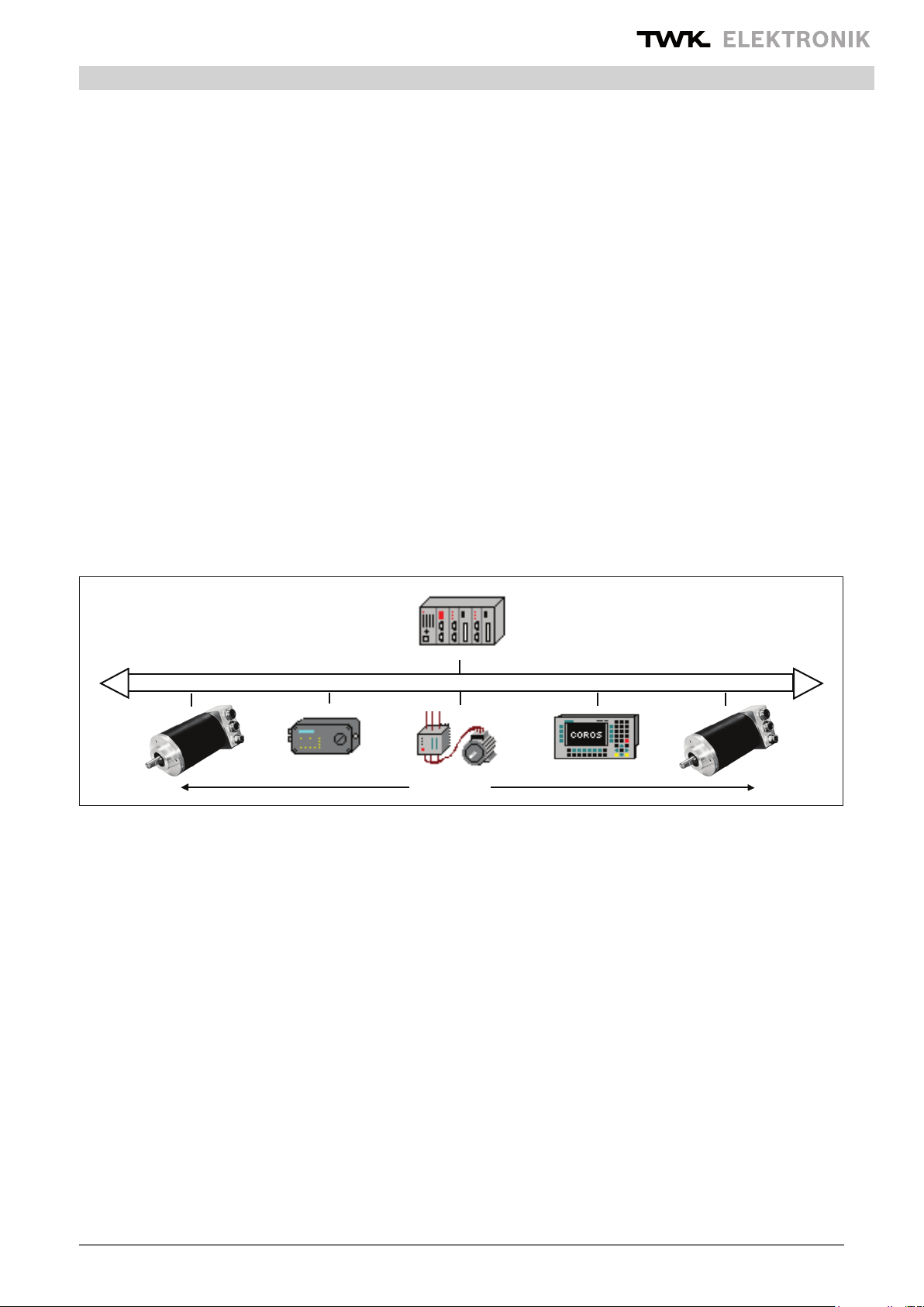
DP slaves
DP master (class 1)
PROFIBUS-DP
2 General
The PROFIBUS is a eld bus standard according to EN 50170. The technical and functional characteristics of the eld
bus system are dened in this standard. The protocol architecture is based on the OSI reference model, in accordance
with the international ISO 7498 standard. Layer 1 (Physical Layer) denes the transmission physics, layer 2 (Data Link
Layer) the bus access protocol, and layer 7 (Application Layer) the application functions. This document is based on
the Prol description for encoders which can be obtained from the PNO /1/. The Probus protocol chip SPC 3 from
Siemens is used as the interface module between the encoder electronics and the bus system.
For PROFIBUS-DP, data exchange between SPS/PC and the decentralised periphery (e.g. encoder) is carried out in
a predominantly cyclical manner. For parameterisation, diagnosis and alarm handling purposes, acyclical communi-
cation functions are also required for intelligent eld devices. In this case, reference must be made to the DIN 19245
Part 1 and 3 or to the EN 50170 standards.
In the case of PROFIBUS-DP, communication in the data back-up layer (layer 2) is carried out via the SRD (Send and
Request Data with Reply) and SDN (Send Data with no Acknowledge) functions.
Mono or multi-master systems may be implemented with PROFIBUS-DP. A maximum of 126 devices (master or
slaves) may be connected to one bus. The denition of the system conguration contains the number of stations,
the allocation of the station address to the I/O addresses, data consistency of the I/O data, format of the diagnosis
messages and the bus parameters which are used.
The parameters of the PROFIBUS subscribers are described in a GSD le (device data sheet). The specications
are executed in accordance with DIN 19245 Part 3 /4/.
Differentiation of the services, and an exact knowledge of these, are especially important for understanding the
PROFIBUS-DP philosophy. A distinction is made between the following in the manual:
Check_Conguration: Conguration of the encoder
Integration of the encoder into the network with various data formats,
or as a programmable or non-programmable slave, is possible.
(Example: F1: programmable (32 bit input/output data) multitour encoder
Data_Exchange: Position data of the encoder
Cyclical enquiry regarding the encoder position. The position value is
depicted as a 16 bit or 32 bit value depending on the conguration.
Setting the preset value
Set_Parameter: Programming parameters
Denition of the operating mode of the encoder and denition of the values
for single turn resolution and total measuring range in units.
Slave_Diagnosis: Diagnosis of the slave subscriber (encoder)
Date: 10.07.2012 Page 6 of 28 user manual no. CRD 10617 FE
Page 7
Installation instructions
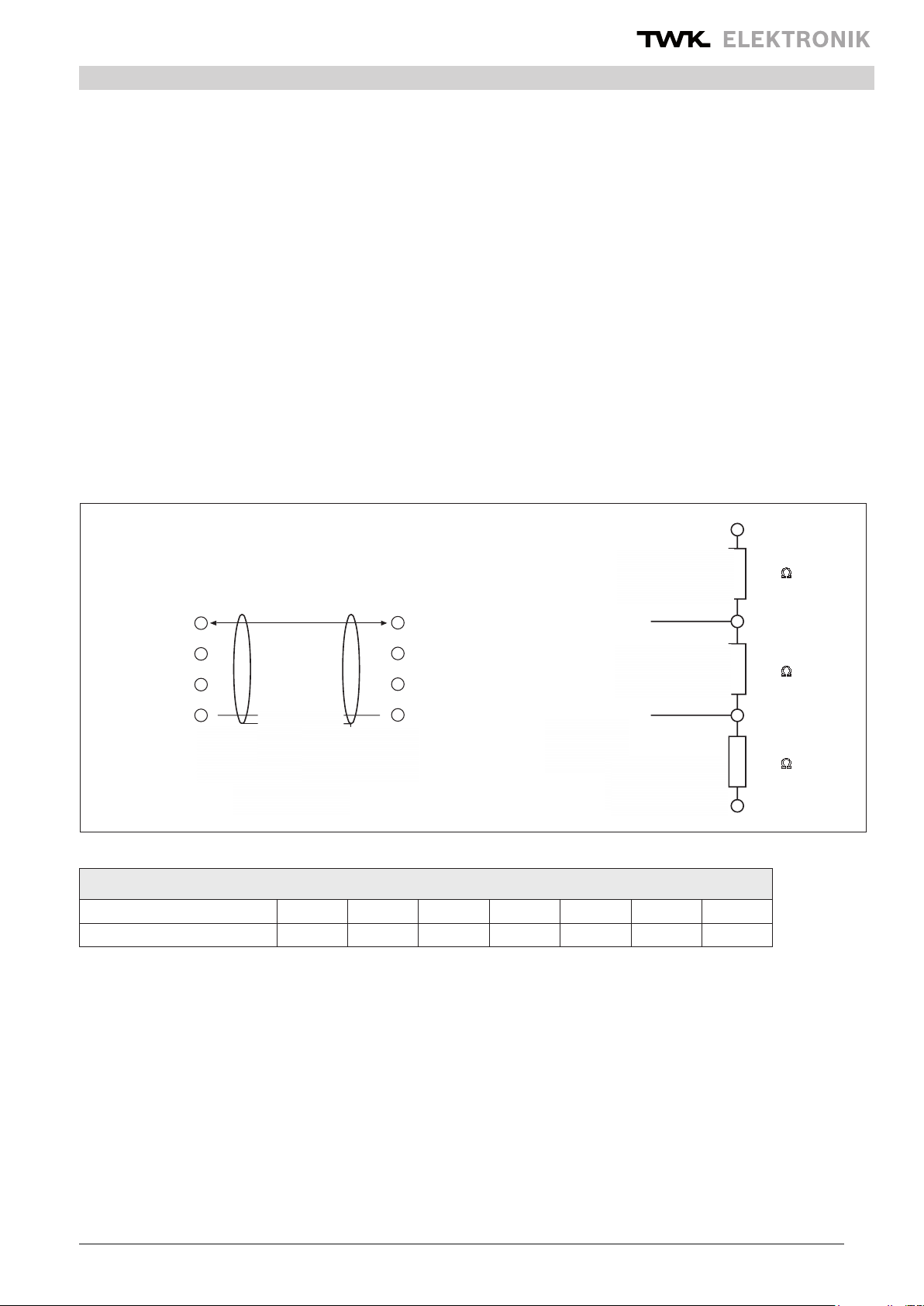
Station 1 Station 2
RxD/TxD-P (3)
DGND (5)
VP (6)
RxD/TxD-N (8) (8) RxD/TxD-N
(5) DGND
(3) RxD/TxD-P
(6) VP
Abschirmung
Schutz-
erde erde
Schutz-
Verkabelung
Busabschluß
Datenleitung B
Datenleitung A
VP (6)
390
220
RxD/TxD-N (8)
390
DGND (5)
RxD/TxD-P (3)
3. Installation instructions for PROFIBUS-DP - RS 485
Basic characteristics of RS-485 transmission technology /2/:
Network topology: Linear bus, terminating resistors for bus termination
Stub lines are only permissible in the case of baudrates < 1.5 MBit/s
Lead: Sheathed, twisted pair cable
Number of stations: 32 stations in each segment without repeaters
Can be extended up to 126 with repeaters.
Plug-type connector: Variants implemented in the case of the CRD model series:
Connecting cap, Round plug RS 25, 12-pin
DESINA (LWL and Cu-version)
(pin assignment according to /1/)
Wiring and bus termination for PROFIBUS-DP /2/, (Note: 9-pin Sub-D plug)
Transmission length depending on transmission speed for cable type A
Baud rate (kBit/s) 9,6 19,2 93,75 187,5 500 1.500 12.000
Transmission length in (m) 1200 1200 1200 1000 400 200 100
Cable type A specications: Characteristic impedance: 135...165 Ohm
Capacitance per unit length coating: < 30 pF/m
Loop resistance: 110 Ohm /km
Core diameter: 0.64 mm
Core cross-section: > 0.34 mm²
Shield
Connection
Data line B
Data line A
Terminating
resistance of the bus
also see: Installation guideline for PROFIBUS -FMS/DP (PNO No. 2.111/2)
Implementation guide DIN 19245 Part 3 (PNO No. 2.001/2)
Date: 10.07.2012 Page 7 of 28 user manual no. CRD 10617 FE
Page 8
Installation instructions
OFF
ON
1234
5
678910
DIP-Schalter
2 : 1
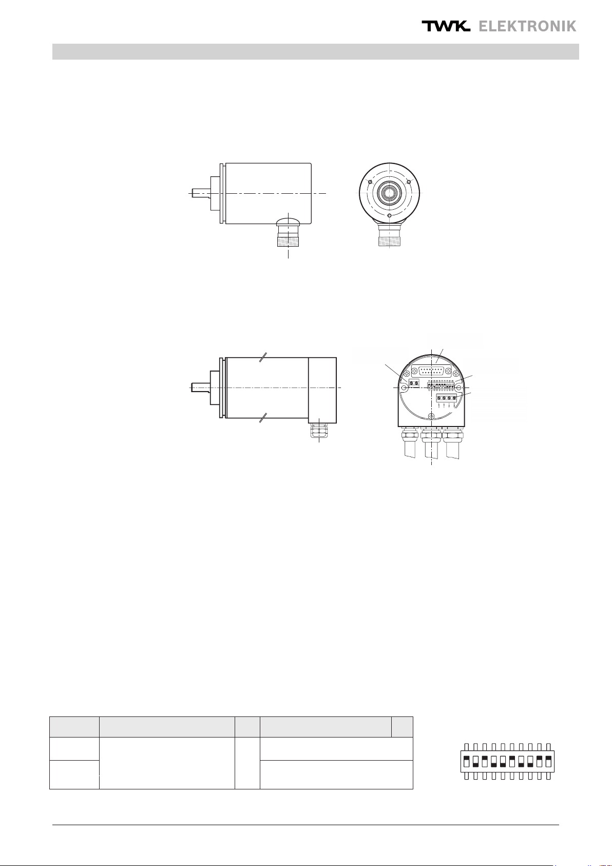
3.1 Connection of encoder with RS plug
The-pin assignment for the 12-pin RS plug (Note: Numeration of the-pins in clockwise direction (view facing contact
side of the bushing), encoder: Bushing) conforms to the prole denition for encoders /1/. The terminating resistors
must be implemented in the counterplug or in the subsequent electronics. For this connection type attention should
be paid to the length of the branch lines in the bus system and the total bus length.
When delivered, each encoder with RS plug has the default address 123. Via the DP master, it is possible to change
the address of a DP slave. The slave address which is to be newly assigned must lie within the range 1-126 (DDLM_
Set_Slave_Add).
3.2 Connection of encoder with connecting cap
Terminal 1
Anschlußklemme 1
Sub-D - Connector
Sub D Stecker
15 poles / sockets
15 polig/Buchse
DIP-Switch
DIP-Schalter
BAA’ B’
+ UB -
ON
OFF
Terminal 2
Anschlußklemme 2
(PROFIBUS)
(PROFIBUS)
The connecting cap for triple connection technology is a T-coupler, which is installed in the PROFIBUS.
It is equipped with three PG connections, which are subdivided as follows:
PG 7: Voltage supply for the encoder (24 VDC +/-)
PG 9: Bus in (Receive/transmit data A,B)
PG 9: Bus out (Receive/transmit data A’,B’)
The encoder is connected via the 15-pin SUB-D plug. In the event of an error, the encoder can be replaced without
time-consuming installation. The connecting cap is disconnected from the encoder by undoing 2 fastening screws
(Note: O-ring seal)
Setting the station/subscriber address is carried out via the DIP switches in the connecting cap.The address range lies
between 1 and 126 (Default address: 123). The address cannot be changed via the DDLM_Set_Slave_Add service.
(Note: GSD le in accordance with encoder version).
Setting the terminating resistors is carried out via the 10-fold DIP switch (9,10) in the connecting cap, which ay be
activated as lead termination as required.
DIP switch – address setting/terminating resistors
Switch 1 2 3 4 5 6 7 8 9 10
0 21
ON = 1 2
... 2
OFF = 0 Address 1 - 126 can be set
(123: Default address)
7
Termination resistors on
n.c.
Termination resistors off
DIP switch
Date: 10.07.2012 Page 8 of 28 user manual no. CRD 10617 FE
Page 9

Installation
PG9PG9 PG7
SRD
LED-Statusanzeigen
UB
Befestigungs-
schrauben M4
C Err
Status LED (connecting cap)
VS SRD C Err
Status LED
Incorrect conguration x x x
Impermissible parameter x x x
Code error
(see diagnosis bytes 62 - 63)
x x
Screw M4
Class 1 Gerätekonguration i.O. x x
Class 2 Gerätekonguration i.O. x x x
VS - power supply, Err - error, C - class, SRD - data trafc
Conguration
4. Conguration function (DDLM_Chk_Cfg)
The absolute encoders with PROFIBUS-DP are classied as follows:
Encoder with Class 1 functionality
Class 1 devices are characterised by the fact that only the position value (16 bit or 32 bit) of the encoder is transmitted
via the bus. No parameterisation of encoder parameters is carried out. In this case, a distinction is made between
the D0 and D1 congurations. The D0 conguration contains the data format: 1 word input data, consistency and D1
contains 2 word input data, consistency.
Encoder with Class 2 functionality
Class 2 devices are characterised by the fact that they can be parameterised via the bus. In this case, a distinction
is made between the F0 and F1 congurations. The F0 conguration has the data format 1 word input data, 1 word
output data, consistency and F1 contains 2 word input data, 2 word output data, consistency .
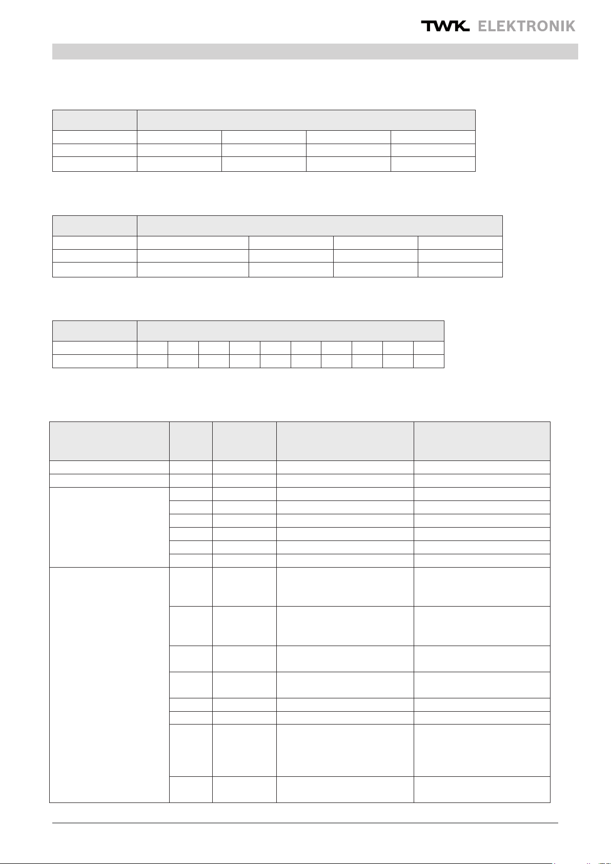
Possible conguratons of the encoder:
Conguration function (DDLM_Chk_Cfg)
Selection Class Data
Class 2 32
Bit In/ Out
Class 2 16
Bit In/ Out
Class 1 32
Bit In
Class 1 16
Bit In
2
2
1
1
32 Bit In/
Output data
16 Bit In/
Output data
32 Bit Input
data
16 Bit Input
data
Identier
byte
F1
F0
D1
D0
Assignment Octet-
No. and MSB/LSB
Octet 1/Bit 7: MSB
Octet 4/Bit 0: LSB
Octet 1/Bit 7: MSB
Octet 2/Bit 0: LSB
Octet 1/Bit 7: MSB
Octet 4/Bit 0: LSB
Octet 1/Bit 7: MSB
Octet 2/Bit 0: LSB
Date: 10.07.2012 Page 9 of 28 user manual no. CRD 10617 FE
Page 10

Data exchange function
5. Data exchange function (DDLM_Data_Exchange)
Input data are data which are transmitted from the peripheral devices to the master or into the bus. The control of
the preset value (see below) is listed as an example of output data at this point.
5.1 Actual position value
The actual position value is output in 16 or 32 bit data format (input data), Please refer to the conguration of the
encoder in the previous chapter.
Actual position value (DDLM_Data_Exchange) 16 bit data format
Input-Data
Octet 1 2
Bit (MSB) 15 - 8 7 - 0 (LSB)
15
8
2
Data
- 2
position value
Actual position value (DDLM_Data_Exchange) 32 bit data format
Input-Data
27 - 2
0
Octet 1 2 3 4
Bit
Data
(MSB) 31 24
31
24
2
- 2
position value
23 - 16 15 - 8 7 - 0 (LSB)
223 -2
16
215 - 2
8
27 - 2
0
5.2 Set preset value
The set preset value function should only be executed when the encoder shaft is stationary!
In order to compare machine position values and the absolute position of the encoder, setting the preset value
is unavoidable in certain cases. The preset value is the position value which is displayed in the reference point.
The possibility of setting the preset value is available in the case of the TWK encoder with class 2 functionality.
The user must note the fact that the preset value must lie within the total measuring range in units. In particular,
this must be taken into consideration when changing the total measuring range in units.
The preset value (binary code) is transmitted in data exchange mode by setting bit 31 (32 bit data format) or bit
15 (16 bit data format).
The following explanations refer to the 32 bit data format.
Setting the preset value in 32 data format
Output-Data
Octet 1 2 3 4
Bit 31 (MSB)30 - 24 23 - 16 15 - 8 7 - 0 (LSB)
30
Data
1/0 2
- 2
24
Preset Control reference value
223 - 2
16
215 - 2
8
27 - 2
0
Date: 10.07.2012 Page 10 of 28 user manual no. CRD 10617 FE
Page 11

Data exchange function
5.3 Example: Setting the preset value in 32 bit data format
Output-Data
Octet 1 2 3 4
Bit 31
Data 1
Preset Control reference value: 8
Following the receipt of this message, an offset value (from the current actual position value and preset value) is calculated by the encoder. If the output position value is equal to the preset value, bit 31 can be reset by the master, as
the preset mode is terminated. The timing diagrams are specied in a separate TY sheet.
Return to normal operation mode, 32 bit data format
Output-Data
Octet 1 2 3 4
Bit 31
Data
0
Preset Control position value: 8
30 - 0
00.0000.0000.0000.0000.0000.0000.1000
30 - 0
00.0000.0000.0000.0000.0000.0000.1000
After bit 31 = 0 has been reset, the encoder operates in normal operating mode. The offset value is stored in the diagnosis data and can be read in the event of a power failure and restarting (Also see Diagnosis messages in Chapter 7).
Date: 10.07.2012 Page 11 of 28 user manual no. CRD 10617 FE
Page 12

Programming parameters
6. Programming parameters for class 1/2 encoder (DDLM_Set_Prm) /4/
The parameterisation data are comprised from bus-specic data and DP slave-specic data.
Bus-specic data: Octet 1-7 Octet 1 – Station status
Octet 2 - WD_Fact_1
Octet 3 - WD_Fact_2
Octet 4 - Min. station delay responder (min T
Octet 5 - Ident_Number 19
Octet 6 - Ident_Number 62H
Octet 7 - Group_Ident
DP slave-specic data: Octet 8-9 Class 1 encoder ( 2 byte User_Prm_Data)
Octet 8-29 Class 2 encoder (22 byte User_Prm_Data)
(See below for description)
Overview ot the encoder programming parameters
Octet number parameter data class remarks
8
SDR
)
9 operating status 1/2
10(MSB) - 13(LSB) Singleturn resolution
14(MSB) - 17(LSB) Total measuring steps
18 - 29
1 to 8192 steps/revolution
(1.000hex)
1 to 16.777.216 steps
(1.000.000hex)
2
2
6.1 Denition of the programming parameters
6.1.1 Operating mode
Logic table for Octet 9 (Operating parameters)
bit number parameter data class remarks
0: CW: Increasing clockwise
Bit 0 Code sequence
Bit 1 Class 2 functionality
Bit 2
Commissioning diagnosis
control
1: CCW: Increasing counter
clockwise
0: not supported
1: supported
0: not supported optional not supported
1,2
1,2
0: disabled
Bit 3 Scaling function status
1: enabled
Date: 10.07.2012 Page 12 of 28 user manual no. CRD 10617 FE
2
enables the scaling
for resolution and total
measuring range
Page 13

Programming parameters
Denition of the operating parameters:
Code sequence: The code sequence denes the direction of rotation in which the position value corre-
sponds to increasing values (viewed in the direction of the shaft).
CW - clockwise
CCW - counter clockwise
Class 2: This operating parameter serves to distinguish between encoders with class 1 or class 2
functions.
Class 1 - Code sequence, release of the class 2 functions
Class 2 - Contains class 1 functions Scaling function control (see below)
Diagnosis: The diagnosis routine enables the extensive examination of all encoder components to ensure
routine: perfect functional capability. The routine is run through each time the device is switched on. If
faults are determined by the diagnosis routine, these are displayed with the alarm bit.
This function is not currently supported.
Scaling function: The scaling function control releases the parameterisation of the single turn resolution
and the total measuring range in units. This function is only effective when changing
the single turn resolution and total measuring range in units parameters. Following the
execution of scaling function control, the position value is recalculated and output.
6.1.2 Measuring units per revolution (Octet 10-13)
Operating parameter resolution
Octet 10 11 12 13
Bit (MSB) 31-24 23-16 15-8 7-0 (LSB)
Data 2
31-224
223-2
16
215-2
8
27-2
0
6.1.3 Total measuring range in units (Octet 14-17)
Operating parameter total measuring steps
Octet 14 15 16 17
Bit (MSB) 31-24 23-16 15-8 7-0 (LSB)
Data 2
31-224
Note: It must be noted that the calculation of the number of revolutions is carried out in 2n powers internally within
the encoder. Regardless of this requirement, the user may programme the desired total measuring range in units
and the desired single turn resolution in accordance with the application. During calculation, the encoder accesses
the next highest 2n power if required. In this case, the values are designated as the actual single turn resolution or
as the actual total measuring range in units, and are displayed as the output value.
Example: desired total measuring range in units : 20480
desired single turn resolution : 4096
desired number of
revolutions : 5
internal encoder calculation
actual total measuring range in units : 32768
actual single turn resolution : 4096
223-2
16
215-2
8
27-2
0
calculated number of
revolutions : 8
Date: 10.07.2012 Page 13 of 28 user manual no. CRD 10617 FE
Page 14

Programming parameters
(Note: The above mentioned note must be taken into consideration in the event of irreversible operation. In the example
which is described, the position 0 is only achieved after 32767 steps and not, as desired, after 20479 steps.)
6.2 Examples for parametration (User_Prm_Data)
Class 1 encoder ( 9 parameter bytes, inclusive 7 bytes bus specid data)*
Class 1 encoder
bus specic data
octet 01 - 07 08 09
data 00 00
data 00 01
operating
status
remarks
Bit 0=0 code sense: CW
Bit 1=0 class1
Bit 0=1 codesense: CCW
Bit 1=0 class1
Class 2 encoder ( 29 parameter data, inclusive 7 bytes bus specic data)*
Class 2 encoder
bus specic
data
octet 01 - 07 08 09 10 - 13 14 - 17 18 - 29
data 00 0A
data 00 0B
operating status
Bit 0=0 code sense: CW
Bit 1=1 class 2
Bit 2=0 no diagnosis
Bit 3=1 scaling on
Bit 0=1 code sense: CCW
Bit 1=1 class 2
Bit 2=0 no diagnosis
Bit 3=1 scaling on
steps/
turn
1.000 1.000.000
100 10.000
total steps
* example contains only DP-slave specic parameter data (see DIN 19245-3)
Date: 10.07.2012 Page 14 of 28 user manual no. CRD 10617 FE
Page 15

Diagnosis messages
7. Diagnosis messages (DDLM_Slave_Diag)
Overview of diagnosis information
Diagnosis octet
number
1 - 6 standard diagnosis information 1, 2
7 extended headerbyte 1, 2
8 alarm messages 1, 2
9 operating parameters encoder 1, 2
10 encoder type 1, 2
11(MSB) - 14 (LSB) resolution 1, 2
15 - 16 measuring range 1, 2
End of diagnosis data for class 1 encoder!
17 additional alarm messages 2
18 - 19 supported alarm messages 2
20 - 21 warning messages 2
22 - 23 supported warnings 2
24 - 25 prol version 2
26 - 27 software version 2
28 - 31 operating time 2
32 - 35 offset 2
36 - 39 manufacturer offsetwert 2
40(MSB) - 43(LSB) resolution 2
44(MSB) - 47(LSB) total measuring steps 2
48 - 57 serial number 2
58 - 59 reserved 2
60 - 63 manufacturer specic diagnosis 2
diagnosis function class
device specic diagnosis
Explanations regarding the diagnosis information:
7.1 Standard diagnosis information (Octet 1-6):
For detailed description, see DIN 19245-3 /4/
(Note: Octet 5,6: Manufacturer identication: 1962H)
This manufacturer identication number is stored in the PNO, and identies the subscriber as a TWK encoder.
7.2 Device-related diagnosis
In the range from Octet 7 up to max. 244 (according to standard /4/), the DP slave may store its specic diagnosis.
7.2.1 Extended header byte (Octet 7):
In the header diagnosis (Octet 7), the length of the extended diagnosis bytes, including the header, is specied.
(Class 1 encoder: 0AH = 10 d
-> 6 (Standard diagnosis) + 1(Octet 7)+ 9 (Octet 8-16) = 16 diagnosis bytes,
Class 2 encoder: 39H = 57d
-> 6 (Standard diagnosis) + 1(Octet 7)+ 56 (Octet 8-63) = 63 diagnosis bytes)
Parameter extended headerbyte
Diagnosis octet 7
Bit 0-5 6 7
Data xxhex 0 0
Denition
length inclusive
header
display of device
diagnosis
Date: 10.07.2012 Page 15 of 28 user manual no. CRD 10617 FE
Page 16

Diagnosis messages
7.2.2 Alarm messages (Octet 8):
Output of the current alarm status. TWK currently supports memory errors only.
Parameter alarm messages
Diagnosis octet 8
Bit 0 1 2 3 4 5-7
Data 0=no /1=yes 0=no /1=yes 0=no /1=yes 0=no /1=yes 0=no /1=yes
Denition Position error
Supply voltage
error
Current to high
Remarks not supported not supported not supported not supported supported
7.2.3 Operating mode (Octet 9)
Current encoder status. This byte is described via the parameterisation of the master, and is read by the
diagnosis string.
Parameter operating mode
Diagnosis octet 9
Bit 0 1 2 3 4-7
Data 0=CW /1=CCW 0=no /1=yes 0=no /1=yes 0=no /1=yes
Denition code sense
class2
functionality
Remarks not supported
diagnosis
function
Commissioning
diagnosis
scaling
function
Memory
error
currently not
assigned
currently not
assigned
7.2.4 Encoder type (Octet 10)
The encoder type is set to multitour absolute. The code is stored in hexadecimal form (00-FFH)
Parameter encoder type
Diagnosis octet 10
Bit 0-7
Data 01hex
Denition Multiturn absolut
7.2.5 Single turn resolution (Octet 11-14)
The maximum possible selection of measuring units per revolution, specied via the single turn resolution of the
encoder shaft. The value is stored in the binary code.
Parameter resolution
Diagnosis octet 11 12 13 14
Bit (MSB) 31-24 23-16 15-8 7-0 (LSB)
Data 2
31-224
223-2
16
215-2
8
27-2
0
7.2.6 Measuring range (Octet 15, 16)
The maximum possible number of revolutions, specied via the single turn resolution of the multitour section.
Depiction in hexadecimal form, e.g. 4096 revolutions = 1000H.
Parameter measuring range
Diagnosis octet 15 16
Bit (MSB) 15-8 7-0 (LSB)
Data 2
15-28
27-2
0
End of diagnosis data for class 1 encoder !
7.2.7 Additional alarm messages (Octet 17)
Not currently assigned.
Date: 10.07.2012 Page 16 of 28 user manual no. CRD 10617 FE
Page 17

Diagnosis messages
7.2.8 Supported alarm messages (Octet 18,19)
The error entitled memory error is currently supported (10H).
Parameter supported alarm messages
Diagnosis octet 18 - 19
Bit 0 1 2 3 4 5-15
Data 0=no /1=yes 0=no /1=yes 0=no /1=yes 0=no /1=yes 0=no /1=yes
Denition Position error
Supply voltage
error
Current to high
Remarks not supported not supported not supported not supported supported
7.2.9 Warning messages (Octet 20,21)
This function is not currently supported.
7.2.10 Supported warnings (Octet 22,23)
This function is not currently supported.
7.2.11 Prole version (Octet 24,25)
Prole version: e.g. 01.00
Commissioning
diagnosis
Memory
error
currently not
assigned
Parameter prol version
Diagnosis octet 24 25
Bit 15-8 7-0
Data 2
15-28
27-2
0
Denition revision number index
7.2.12 Software version (Octet 26,27)
Software version: e.g. 01.00
Parameter software version
Diagnosis octet 26 27
Bit 15-8 7-0
Data 2
15-28
27-2
0
Denition revision number index
7.2.13 Operating time (Octet 28-31)
This function is not currently supported. The operating time default is set as FFFF FFFF
encoder prole.
in accordance with the
hex
7.2.14 Offset value (Octet 32-35)
The offset is the shift in the zero point on setting the reference point, with reference to the output
(according to the calculation).
Parameter offset value
Diagnosis octet 32 33 34 35
Bit (MSB) 31-24 23-16 15-8 7-0 (LSB)
Data 2
31-224
223-2
16
215-2
8
27-2
0
7.2.15 Manufacturer offset value (Octet 36-39)
The manufacturer offset is the shift in the zero point of the encoder with regard to its physical zero point.
The manufacturer offset value is not currently supported (Assignment: 00 00 00 00H).
Date: 10.07.2012 Page 17 of 28 user manual no. CRD 10617 FE
Page 18
Diagnosis messages
7.2.16 Single turn resolution (Octet 40-43)
In this case, the single turn resolution set in the parameter programme is reected.
Parameter single turn resolution
Diagnosis Octet 40 41 42 43
Bit (MSB) 31-24 23-16 15-8 7-0 (LSB)
Data 2
31-224
7.2.17 Total measuring steps (Octet 44-47)
In this case, the total measuring units per revolution set in the parameter programme is reected.
Parameter total measuring steps
Diagnosis Octet 44 45 46 47
Bit (MSB) 31-24 23-16 15-8 7-0 (LSB)
Data 2
31-224
7.2.18 Serial number (Octet 48-57)
This parameter is not currently supported.
Parameter serial number
Diagnosis Octet 48 49 50 51 52 53 54 55 56 57
Data 2A 2A 2A 2A 2A 2A 2A 2A 2A 2A
223-2
16
223-2
8
215-2
16
215-2
8
27-2
0
27-2
0
7.2.19 Reserved for future use (Octet 58,59)
7.2.20 Manufacturer-specic diagnosis (Octet 60-63)
Octet Nummer Bit Deniton Function Remarks
60 0 - 7 reserved
61 0 - 7 reservied
62 0 ErrEE EEPROM error reset encoder
1 ErrMSA MSA error reset encoder
2 ErrXRAM error external RAM reset encoder
3 ErrExp error connectiong cap reset encoder
4 IniFlg initialising EEPROM
5 - 7 reserved
63 0 ErrCRCO CRC0 error re-program and restart
encoder
1 ErrCRC1 CRC1 error re-program and restart
encoder
2 ErrPar parameter value error re-program encoder
3 ErrSkal scaling error
4 ErrMem ROM-Code error reset encoder
5 ErrInt internal controler error reset encoder
6 ErrPre referenz value error reference value must be
in the range of: 0 - total
measuring steps - 1
7 ErrStat unknown command
Date: 10.07.2012 Page 18 of 28 user manual no. CRD 10617 FE
Page 19

Diagnosis messages
* If a faulty preset value is input, control bit 31 must be set to zero before inputting the correct preset value in order to eradicate
the error. The preset value can subsequently be reset after setting control bit 31 to 1. After resetting bit 31 to the value zero, the
position value may then be output.
7.2.21 Example of diagnosis message
Octet 1 2 3 4 5 6 7 8 9 10 11 12 13 14 15 16
01-16 00 0C 00 02 19 62 39 00 0A 01 00 00 10 00 10 00
17-32 00 00 10 00 00 00 00 01 00 01 70 FF FF FF FF 00
33-48 00 0A D4 00 00 00 00 00 00 10 00 01 00 00 00 2A
48-63 2A 2A 2A 2A 2A 2A 2A 2A 2A 00 00 00 00 00 00
Explanation:
Octet:
1 - 6
7 Extended header byte 39 hex 63 diagnosis bytes
8 Alarm messages 00 hex No alarms are present
9 Operating mode 0A hex
10 Encoder type 01 hex Multitour, absolute
11 - 14 Single turn resolution 1000 hex 4096 S/U
15 - 16 Measuring range 1000 hex 16.777.216 Total measuring range
17
18-19
20-21 Warning messages 0000 hex wird nicht unterstützt
22-23
24-25 Prole version 01.00 Hardware version: 1.00
26-27 Software version 01.70 Software version: 1.70
28-31 Operating time FFFFFFFF hex
32-35 Offset value 00000AD4 hex Offsetwert
36-39
40-43 Single turn resolution 00001000 hex 4096 S/U
44-47
48-57 Serial number 2A2A2A2A2A2A2A2A2A2A hex
58-59
60-63
Parameter Data Remarks
01 00 hex
Response monitoring activated,
bit 2 set to 1
Parameterisation via master with
address 02
CW, class 2, diagnosis: no, scaling
yes
Standard diagnosis
information
Additional
alarm messages
Supported
alarm messages
Supported
alarm messages
Manufacturer
offset value
Total measuring units
per revolution
Reserved
for future use
Manufacturer-
specic diagnosis
02 0C hex
03 00 hex
04 02 hex
05 - 06 1962 hex Ident_Number CRD
00 hex No alarms are present
0010 hex Memory error is supported
0000 hex wird nicht unterstützt
00000000 hex Is not currently supported
01000000 hex 16.777.216 Schritte
0000 hex
00000000 hex No errors are present
Date: 10.07.2012 Page 19 of 28 user manual no. CRD 10617 FE
Page 20

Simatic Step7
8. Simatic Step7
This Chapter explains the procedure for integrating the TWK encoder into the probus of Siemens S7 control system,
and the set up and the utilisation of the example programmes for Step7. The basis of the documentation is Step 7
Version 5.1.
8.1 Integration of the TWK probus encoder
Prerequisites: You have congured your hardware in accordance with the structure of your control system, and
have installed a probus subnetwork.
8.1.1 Installation of the GSD le
- The GSD-le and the encoder symbols (bitmaps) are available under www.twk.de menu Documentation
- Close all projects in the hardware conguration.
- In the hardware conguration, select Install new GSD under Options.
- Select the GSD le which corresponds to your encoder:
Version with connecting cap: TWKZ1962.GSD
Version with plug connection: TWKL1962.GSD
- Update the Step7 hardware catalogue via Options, Update Catalog.
8.1.2 Installation of the TWK encoder symbol
Via the installation of the TWK encoder symbol, your encoder is not depicted as an unknown subscriber in the
hardware conguration, but assumes the appearance of your encoder. This is not, however, of signicance as
regards the function of the encoder.
In order to install the symbol (bitmap), copy the two les: CRD_Z_an.BMP and CRD_L_an.BMP into the C:\Siemens\
Step7\S7Data\NSBMP\ directory (if C: is your S7 drive). The symbols rst appear after restarting the Simatic Manager.
8.1.3 Selection of the TWK encoder from the Step7 hardware catalogue
- After opening the hardware catalogue, you will nd, under Probus-DP, Additional Field Devices, General,
the TWK Probus encoder "Encoder CRD plug" (encoder in plug version) or "Encoder CRD cap" (encoder
with connecting cap).
- Now open your project, mark the bus and integrate the encoder into the bus by double-clicking onto the
corresponding line in the hardware catalogue (Encoder CRD plug or Encoder CRD cap).
8.1.4 Conguration of the encoder
After the appropriate encoder type has been selected in the (hardware) Catalog, the following window appears for
the selection of encoder functionality and single turn resolution.
In this case, select class 1 or class 2 functionality and 16 or 32 bit single turn resolution in accordance with your
requirements. (See Chapter 4)
Date: 10.07.2012 Page 20 of 28 user manual no. CRD 10617 FE
Page 21

Simatic Step7
8.1.5 Allocation of probus address
If you have selected your nominal conguration, the following window, in which you must specify the probus address
set in the encoder, appears. For the example programmes, please select address 123 for the rst and address 122
for the second encoder here.
Note: The probus address of the encoder is set, in the case of the cap version, via dip switches (See Chapter 3.2)
and, in the case of the plug version, via software (See Chapter 8.2).
In addition, select your planned Probus in the Subnet, and quit the window with OK.
The encoder subsequently appears as a subscriber in your probus. Depending on the conguration and address,
this may appear as follows:
Double-clicking for
the diagnosis address
configuration (
Double-clicking for the
address configuration and
parameter programming
(
See 8.1.6 und 8.1.7)
See 8.1.8)
The value for Module / DP-ID results from the conguration which is selected. The values for I/O address are default
values which may vary depending on the control system.
Date: 10.07.2012 Page 21 of 28 user manual no. CRD 10617 FE
Page 22

Simatic Step7
8.1.6 Setting the I/O
addresses (S7 addresses)
Double-clicking onto the “Slot
0” line opens the Properties
- DP slave window with the
Address / ID and Parameter
Assignment registers. In the
Address / ID registers, under
output (in the case of class 2
encoder only) and input, the
addresses under which the
encoder is to be addressed
in S7 must be allocated. The
other entries in this register
should not be changed. The
following Figure depicts an
example of this register for a
class 2 encoder with 32 bit
single turn resolution.
For the example programme,
please input address 100 for
outputs and inputs.
8.1.7 Parameterisation of
the encoder
Via the Parameter Assignment
register, the following window,
in which the characteristics of
the encoder can be dened, is
accessed. The parameters of a
class 2 slave are shown. In the
case of a class 1 slave, only the
code sequence parameter can
be set here.
(See Chapter 6)
Date: 10.07.2012 Page 22 of 28 user manual no. CRD 10617 FE
Page 23

Simatic Step7
8.1.8 Setting the diagnosis address
Setting the diagnosis address is only required if the special probus diagnosis functions are used within the S7
programme.
So that the diagnosis range of the encoder can be accessed within the S7 programme, a special S7 diagnosis address
must be allocated to this. This address may lie within the entire peripheral range of the control system. It does not,
therefore, occupy any input/output addresses.
By double-clicking onto the encoder symbol, the Properties - DP slave window appears with the General register.
For the example programme please specify diagnosis address 200 for the rst encoder and 202 for the second encoder.
Following conrmation with OK, the encoder is congured and parameterised. The hardware conguration can
now be translated and transferred into S7.
8.2 Setting the subscriber address in the case of the plug-version encoder
According to Siemens, the prerequisites for allocating a new address are as follows:
1. No further DP master is contained in the PROFIBUS network.
2. At least one DP slave exists in the PROFIBUS network.
3. A PROFIBUS address has already been directly allocated to each DP slave in the
PROFIBUS network (either via software via PG - DP slave direct connection
or via setting the switches on the DP slave; Assignment is DP slave-dependent,
therefore consult the DP slave manual)
4. You have connected the programming device to the PROFIBUS network via a stub line
(See the manual regarding the DP master).
(See on-line help under Assignment of probus address” in the Simatic Manager)
Date: 10.07.2012 Page 23 of 28 user manual no. CRD 10617 FE
Page 24

Simatic Step7
I.e. if the encoder is not the only slave on the probus/MPI card, all slaves contained in the bus must possess a
unique (allocated only once) address, and the master (S7-CPU) must be disconnected from the bus. It is therefore
impossible, for example, to simultaneously connect two encoders with address 123 to the bus and to then assign a
new address to one of the two.
If the encoder whose address is to be changed has already previously been used in bus operation, this must be
rendered potential-free before it can be set to a new address.
Address setting is carried out in the Simatic Manager under “PLC , Assign PROFIBUS Address”. If the encoder is
connected to the probus/MPI interface of your programming device, the depicted dialogue appears.
This displays the current address of the encoder, and requests the input of the new probus address. If this is conrmed
with Apply, the new address is stored in the encoder in a zero-voltage-protected manner. The dialogue subsequently
displays the new address as the current address.
8.3 Example programmes
In the internet several S7 archive les are available, which contain S7 example programmes which have been
generated by TWK for working with the TWK probus encoder. The programmes have been developed for a CPU3152DP, and have been designed such that no periphery other than a TWK probus encoder is required. There is one
project for encoders with class 1 functionality and one for encoders with class 2 functionality. Each project contains
several programme folders for different application cases. The standard ”Sources” and ”Blocks” folders are located
beneath the programme folders.
The TWK examples only contain modules which have been generated with the KOP/FUP/AWL Editor. The generation
language was FUP. Within the modules, comprehensive documentation is made available on the basis of network
comments.
TWK cannot undertake to provide any guarantee for the function of these programmes on customers’
systems/control systems.
Programmes in the archive les:
- TWKDPCL1.ARJ : Class 1 project with Diagnosis and Istwert programme folders, comments in German
- TWKDPCL2.ARJ : Class 2 project with Diagnosis, IstRef and Istwert programme folders, comments in German
- DP_C1_GB.ARJ : Class 1 project with Diagnosis and Istwert programme folders, comments in English
- DP_C2_GB.ARJ : Class 2 Project with Diagnosis, IstRef and Istwert programme folders, comments in English
Because of a modication in the handling of the used system function SFC13 the examples for the diagnosis in the
above programmes do not work with actual CPUs. Therefore a new programm example is available (please refer to
the additional information in document no. 12532).
- Diag_neu: reading of diagosis data with SFC13 with german comments
- Diag_new: reading of diagosis data with SFC13 with english comments
8.3.1 The TWKDPCL1 project
The following Figure shows the class 1 project programme folders:
Date: 10.07.2012 Page 24 of 28 user manual no. CRD 10617 FE
Page 25

Simatic Step7
Program Istwert: The program Istwert is comprised only of an OB1 and is intended to briey show the manner in
which the actual position value of the encoder is accessed within the S7 programme.
Program Diag1: In addition to the program Istwert, the Diag1 programme also contains error handling for a class 1
encoder. It contains, amongst other things, OB86 for detecting the failure of the encoder, and OB82 for detecting a
diagnosis request on the part of the encoder. Step7 system function SFC13 is used to read the diagnosis range out.
(The diagnosis range of the class 1 encoder is 16 bytes. See Chapter 7)
Program Diag2: The Diag2 programme provides the same functionality as Diag1, but is designed for two encoders.
Within each programme, a selection may be made between functions for a 16 or 32 bit-wide encoder input. To achieve
this, either the 16 or the 32 bit function is simply provided with a ”1” signal (one-marker M 0.1) at the EN input, and
the non-required function with a ”0” signal (zero-marker M 0.0).
8.3.2 The TWKDPCL2 project
The class 2 project contains the following programme folders:
Program Istwert: Identical to class 1 programme
Program IstRef: The program IstRef contains the reading out of the actual position value and, in addition, the
setting of a preset value, which is possible in the case of class 2 functionality.
Program Diag1: In the same manner as Diag1 from the class 1 project, the Diag1 programme contains the error
handling of a class 2 encoder. In this case, the scope of the diagnosis range is 63 bytes.
Program Diag2: Once again, Diag2 is the variant of Diag1 which is extended to encompass two encoders.
8.3.3 Installation of the example programmes
Prerequisites:
- You have generated a project and have inserted a control system into this with its hardware conguration.
This may appear as follows, for example:
· In the hardware conguration, you have connected one or two encoders with the following settings to a
probus subnetwork:
First encoder: Probus address 123
Inputs/outputs: From address 100
Diagnosis address: 200
Poss.: Second encoder: Probus address 122
Inputs/outputs: From address 110
Diagnosis address: 202
Date: 10.07.2012 Page 25 of 28 user manual no. CRD 10617 FE
Page 26

Simatic Step7
Installation:
- In the Simatic Manager, select File, Retrieve. Change the le type to *.arj and select the downloaded le
- In the next window, specify your project directory (normally S7proj).
- Via integration with OK, the dearchiving programme is started. After terminating this, you will nd your
selected TWK example project in your S7 project directory.
- If you now select File, Open, User project, you will be provided with a list of the projects available on your
system. If the example project is not yet available here, select Browse and search for the TWKDPCL1.s7p
(or TWKDPCL2.s7p) le under the TWK example project.
- Open the example project so that you now have both projects, your own and the example project, open. This
may then, for example, look like the Figure on the next Page.
- Select a subordinate S7 programme folder of the TWK example project. (In this case, either Diag1, Diag2, IstRef
or Istwert. Also see: Chapter 8.3.1)
- Copy all of the module container’s modules from the selected programme folder ( e.g. Diag1 from
TWKDPCL2 ) into your own project’s still empty module container (e.g. S7 programme (1) from DP_CLAS2 ).
(Note: Each module container, even an empty one, contains at least one OB1; this is, of course, also empty,
and can therefore be overwritten.)
- If you have installed a class 2, 16 bit encoder, and have selected the ActualRef or Diag1/2 programme, you
must, in order to set the preset value, release the FB10 in the OB1, i.e. supply the EN input with M 0.1 and
block the FB11 (s), i.e. supply the EN input with M 0.0.
- If necessary, replace the M 1.0 – Acknowledge message and the M 10.0 (and M 10.1 in the case of two
encoders) – Set the preset value, with your signals.
- Transfer all modules into the control system.
- Now call up the OB1 in the on-line view, and switch Test, Observe on, in order to have the current values of
the encoder displayed on the monitor.
- For ActualRef and Diag1/2 programme only: Enter a preset value into DB100 data doubleword 0 (for the
second encoder, DB100 data doubleword 8), and set this with the M 10.0 (or M 10.1). If the preset value lies
outside of the parameterised measurement range of the encoder, the corresponding error message is set in
OB1.
Date: 10.07.2012 Page 26 of 28 user manual no. CRD 10617 FE
Page 27

Simatic Step7
8.3.4 Explanations regarding the example programmes
Each programme folder contains a symbol table, which contains all global variables of the maximum expansion (class
2 project, Diag2 programme).
The programme structure of this maximum expansion is explained in the following. The reference data provide the
following overview: (The symbolic name is always contained in the round brackets)
Cyclical programme:
- Reading the actual value in
- Setting the preset value (class 2 only) for
16 bit (FB10) or 32 bit (FB11)
- Error messages from OB82
- Error messages from OB 86
OB82 is run through as soon as a DP slave
places a diagnosis request (in the case of an
incoming and outgoing event). In OB82, the
diagnosis data are collected by FB13 or SFC13.
The errors are reported in OB1.
OB86 is called up by the system in the event of
the failure of a DP slave (e.g. power failure), etc.
(in the case of an incoming and outgoing event).
The failed encoder is determined in FC16 and
is displayed in OB1.
The entire diagnosis range of the disturbed encoder is always read out via system function SFC13 (16 bytes in the
case of class 1 and 63 bytes in the case of class 2). The address of this slave is provided by OB82 in its local data.
Only the manufacturer-specic error message bits are evaluated, and of these, only those which may occur in Data
Exchange Mode (in normal bus operation). Errors which can occur during bus initialisation cannot be detected by
OB82. In this case, the error messages must be read out via the Diagnosing hardware function of the Step7 package.
Date: 10.07.2012 Page 27 of 28 user manual no. CRD 10617 FE
Page 28

Scope of delivery
9. Scope of delivery
The scope of delivery includes: - Encoder with DP interface
- Pin assignment TY XXXXX (depending on the device variant)
Remark:
The GSD-le, the complete documentation and the example programms are available for download in the internet
www.twk.de under documentation
Literature
10. Literature
/1/ PROFIBUS Prole for Encoders
Order No. 3.062
1997, PROFIBUS User Organisation Regd. Assoc.
Haid-und-Neu-Str. 7
D-76131 Karlsruhe
/2/ PROFIBUS
Brief Technical Description
Version: April 1997
PROFIBUS User Organisation
/3/ DIN 19245 Part 1 PROFIBUS
Process Field Bus Transmission Technology, Bus Access and Transmission Protocol,
Service Interface for Application Layer, Management
/4/ DIN 19245 Part 3 PROFIBUS
Process Field Bus Decentralised Periphery (DP)
/5/ SIEMENS SINEC L2
SPC 3 Siemens PROFIBUS Controller
User Description Order No.: 6ES7 195-0BD00-8AA0
Appendix A
Appendix A: Encoder terms
Parameter: Explanation
Measuring units per revolution: The single turn resolution species the number of measuring units per
revolution (360°).
Measuring range: The measuring range species the maximum number of revolutions.
Specication of the revolutions must be carried out in 2
Total measuring range in units: The total measuring range in units is revealed as follows:
Total measuring range in units = Single turn resolution x Measuring range
Code sequence: The code sequence species the direction of rotation in which the output code
of the encoder corresponds to increasing values.
A distinction is made between the following depending on the direction of rotation:
CW - clockwise, clockwise direction of rotation
CCW - counter clockwise, anti-clockwise direction of rotation
(viewed in the direction of the shaft)
Preset value: The preset value is the value which appears in the encoder’s output value
parameter according to the preset function.
n
powers.
Date: 10.07.2012 Page 28 of 28 user manual no. CRD 10617 FE
 Loading...