

Twitoplast OPAL RC-11 Operating And Manual Instructions

OPAL RC-11
Operating
And Manual
instructions

Remote control for
the proportional
damper :
congratulates you on your purchase of the remote control and receiver for
the proportional damper. The
measurement in one room. The
for quick and easy installation and optimum performance to assure perfect and uniform air
conditioning.
is part of a smart system that controls the temperature
system was designed by the company’s engineers
Contents:
Part 1 - Before Installation
Part 2 - Installation of
Damper and Connecting to the Power Supply Box
Part 3 - Checking regularity of the System
Part 4 - Characteristics
Part 5 - Operating Instructions and Functions of the Buttons
& Receiver for the Proportional
Page
2-3
4-5
6
7
8-15
1
1. Before Installation
1.1 Auxiliary Equipment
1.1.1 Power Supply Unit Type C315 (not included)
Type No. of channels Supply
C315 1 One remote control
C315 › 2 2 Up to 2 remote controls
C315 › 4 4 Up to 4 remote controls
The remote control must be used only with a C315 power supply box.
1.1.2 Cable with Quick Connection Connector
The following standard length cables with quick-connecting connectors between the receiver and the
power Supply Box may be used with:
(cable 140106 included)
Length Code
6 m 140106
10 m 140110
15 m 140115
20 m 140120
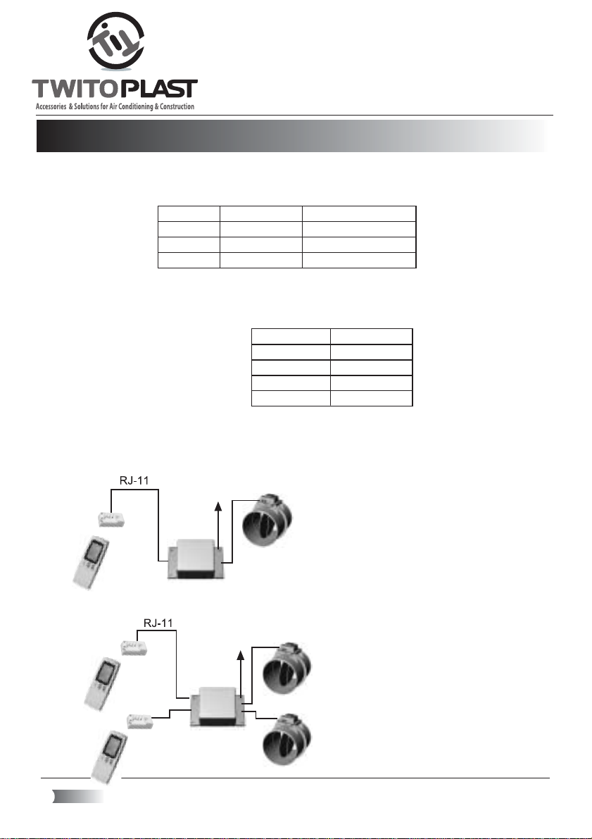
1.2 Alternative System Configurations.
The system enables to connect up to four remote controls and dampers to one power supply box and
thus provides flexibility and comfort in installation according to the requirements on site. The connection
possibilities are detailed as follows:
230
Volt (V)
One Channel
Connection one remote to one Power Supply Box
C315 and one damper.
230
Volt (V)
Two Channels
Connection of up to two remote controls
to one Power Supply Box C315 - 2
And up to two dampers.
2
RJ-11
230
Volt (V)
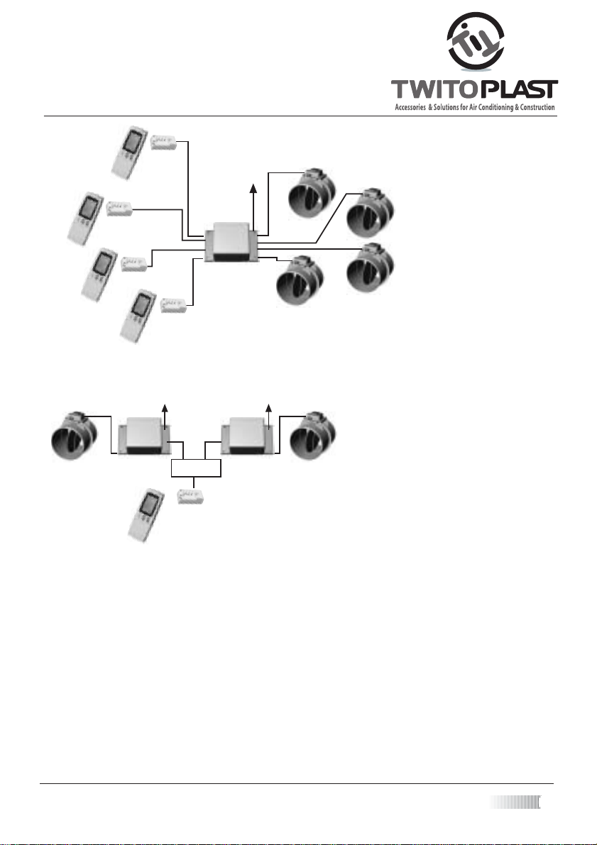
230
Volt (V)
Four Channels
Connecting of up to four remote controls
To one Power Supply Box C315 - 4
And up to four dampers.
230
Volt (V)
RJ-11RJ-11
Distributor
Two Units One Channel
Connecting one remote control
To two Power Supply Boxes and two dampers (in a similar way
3 power supply boxes and dampers can be connected)
BEFORE STARTING TO WORK...
1.3 Warning for Safe Installation
- Before starting to work, make sure that the power supply cable is disconnected from the 220v electrical
network!
- The installations must be carried out by a qualified electrician or a certified technician.
- For the connection between the receiver and the power supply box, use only cables with quickconnecting connectors, supplied by the manufacturer.
- The connection to the supply voltage must be carried out only with a standard cable to the end of
which a standard connector has been connected.
3
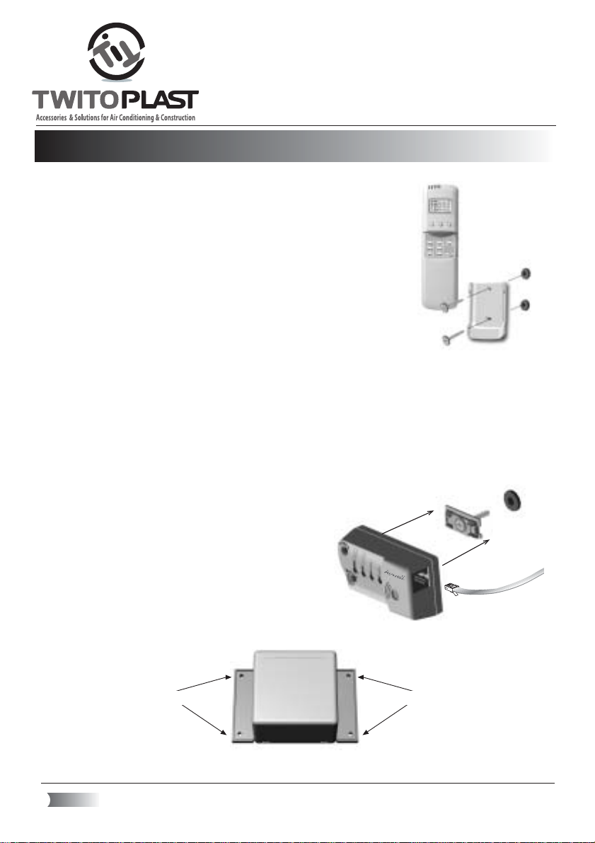
2. Installing the RC- 10 & Receiver to the Power Supply Box
2.1 Installation of the receiver and remote control holders
Holder
Remote
Control
Remote
Control
Holder
Pin
Pin
Pin
2.1.1 Installation of the remote control holder
- Choose a location for the holder, considering the customer’s requirements
-Install the remote control holder in air conditioned environment on a
spot, where the temperature can be detected best.
- Height of 1.5 m above the floor is recommended.
The holder should not be installed on an external wall, near a stairway,
or an area that is exposed to the external temperature, (radiation from
the sun, heating elements, air pocket etc.). The remote control holder
should be installed under the receiver. It can also be installed in another
place only in a straight visual line from the receiver. For the installation
of the remote control holder, use two screws.
2.1.2 Installation of the receiver C612 (the receiver should not be opened.)
- The receiver has to be installed close to the ceiling, or in a location considering the requirement of
the customer. Ensure that the receiver will be at a visual line from the
remote control holder.
- In order to install the receiver, mark the screw locations on the wall with the measurable tag provided..
- Apply one dowel pin, apply the screw via the holding device and tighten the screw fastening the
holder to the wall as much as possible. Plug the RJ-11 wire into the socket on the side of the receiver.
Adjust the receiver according to the markings and fasten it to the holding device (until you hear a
“click”).
2.2 Connecting to the Power Supply Box
2.2.1 Power Supply Box Location
- Connect the power supply box to the air conditioner or to the wall using four screws. the power supply
box should be accessible for service .
Screw
Screw
WARNING: The Power Supply Box must not be installed close to lighting accessories or where it is
exposed to water and humidity.
4
RJ11
2.2.2 Connecting the Power supply box to the Receiver
- Mark the cable with the snap connection (RJ › 11) with a color sticker “flag” (stickers provided with
the power supply box).
- Connect the receiver to the power supply box using a cable with a quick-connection (RJ › 11).
- Connect the power supply box to the damper motor with a multiple line flexible cable.
Connection details:
Connection to motor
Damper motor Power supply box Receiver
+ -
D1- D1+
+ -
D2- D2+
+ -
D3- D3+
+ -
D4+ D4+
Receiver connection
T1
T2
T3
T4
T1
T2
T3
T4
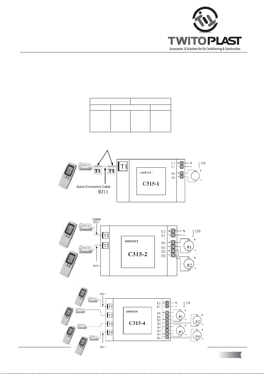
Connection diagrams:
Connection of the receiver to the power supply box: C315 › 1 one channel
zero
volt
zero
Phase
Motor
Phase
Motor
volt
Code
Power Supply Box
One Channel
Connection of the receiver to the power supply box: C315 › 2 two channels
Code
Power Supply Box
Cable
2 Channels
Motor
Cable
Connection of the receiver to the power supply box: C315 › 4 four channels
Cable
zero
volt
Code
Power Supply Box
4 Channels
Cable
Phase
Motor
Motor
Motor
Motor
5
 Loading...