

Page 1

TWITE INSTRUMENTS THERMOSTAT MODEL TD-196 OPERATING MANUAL
TWITE INSTRUMENTS PTY. LTD. ®
A.C.N. 050 199 758
No. 3 STANLEY St. MOOROOPNA VICTORIA AUSTRALIA 3629.
PO. Box 176 SHEPPARTON VICTORIA AUSTRALIA 3630.
Telephone (058) 253-161 FAX (058) 252-042
1
Page 2

TWITE INSTRUMENTS THERMOSTAT MODEL TD-196 OPERATING MANUAL
© Copyright 1994 - 1999 Twite Instruments Pty. Ltd. All rights reserved.
No part of this publication may be reproduced, translated into another language,
stored in a retrieval system, or transmitted, in any form or by any means, electronic,
mechanical, photocopying, or otherwise without the prior written consent of
TWITE INSTRUMENTS Pty. Ltd.
Every precaution has been taken in the preparation of this publication.
TWITE INSTRUMENTS assumes no responsibility for errors or omissions. Neither
is any liability assumed for damages resulting from the use of the information
contained herein.
Specifications of the THERMOSTAT Model TD-196 are subject to change without
notice.
Twite Instruments Pty. Ltd. or any of its Partners, Principals or Employees cannot be
held responsible or liable for any loss of product, produce or buildings where any of
Twite Instruments Pty. Ltd. Products are found to be responsible for the loss of any
product, produce or buildings.
IBM ® is a trade mark of International Business Machines.
EPSON ® is a trade mark of EPSON.
WINDOWS & WINDOWS 3 ® is a trade mark of Microsoft.
2
Page 3

TWITE INSTRUMENTS THERMOSTAT MODEL TD-196 OPERATING MANUAL
CONTENTS
INSTALLATION
MOUNTING 6
POWER & SOLENOID CONNECTION 6
SENSOR INPUT CONNECTIONS 7
SENSOR POSITIONING 8
PRINTER CONNECTION (RS485) 8
ALARM OUTPUTS 9
DISPLAY CONTRAST ADJUST 33
DISPLAY FUNCTIONS
DISPLAY LED 10
SETTING LED 10
D/M/S LED 11
REFRIG LED 12
SUCTION LED 12
FANS LED 12
ALARM LED 12
KEYBOARD FUNCTIONS
"SET" KEY 12
"ENT" KEY 13
" s " "DIS" (up arrow) KEY 13
" t " "DIS" (down arrow) KEY 13
PASSWORD
USING PASSWORD 14
CHANGE PASSWORD 14
PASSWORD UNKNOWN 14
SELECTING CHANNELS 15
FUNCTION NUMBERS 16
3
Page 4

TWITE INSTRUMENTS THERMOSTAT MODEL TD-196 OPERATING MANUAL
CONTENTS
SET POINT PARAMETERS
TEMPERATURE 17
DIFFERENTIAL 18
SET POINT USAGE TIMES 18
HIGH ALARM TEMPERATURE SET POINTS 19
LOW ALARM TEMPERATURE SET POINTS 19
HIGH ALARM DELAY SET POINT 20
LOW ALARM DELAY SET POINT 20
SET DEFROSTS 21-22
DEFROST AUTO OFF 23
DEFROST MANUAL ON OFF 23
CONTROL ON OFF 24
FANS CONTINUOUS AUTOMATIC 24
HIGH ALARM ACTIVE (OVERRIDE) 25
LOW ALARM ACTIVE (OVERRIDE) 25
DIFFERENTIAL TYPE 26
POWER ON DELAY 27
UNIT NUMBER 27
COOLING OR HEATING 2 8
SET REAL TIME CLOCK 28
CALIBRATE REAL TIME CLOCK 29
PRINT 29-30
DATA LOGGING 31
PASSWORD ON OFF 32
CHANGE PASSWORD 32
PUMP DOWN SET POINT 33
DISPLAY INTENSITY 33
DAILY SET POINTS 34
LINE FEED YES NO 35
CHANNELS CONNECTED 35
CHANNELS TO SCAN 36
SCAN TIME 36
SCAN YES NO 36
CONTROL CHANNEL 37
RESET MAXIMUM MINIMUM 37
BAUD RATE SET 38
LONG TERM OR PULL DOWN MODE SET 38
4
CALIBRATION VALUES 62
Page 5

TWITE INSTRUMENTS THERMOSTAT MODEL TD-196 OPERATING MANUAL
CONTENTS
PRINTER COMMUNICATIONS 40
CALIBRATING AND DEFAULT VALUES :-
CALIBRATION BUTTON ACCESS HOLE 42
CALIBRATE VALUES CHECK & ALTER 43-44
CALIBRATION VALUES UPDATE 44
TEST DISPLAYS 44
MEMORY (RAM) TEST 44
RESET DATA LOGGING 45
RESET PASSWORD 45
SET PARAMETERS TO A DEFAULT VALUE 45
KICK START REAL TIME CLOCK 45
CALIBRATE SENSORS 446-47
START UP DEFAULTS VALUES 47
SPECIFICATIONS 48-50
ERROR MESSAGES 51-52
REMOTE DISPLAY MODULE
MOUNTING 53
POWER SUPPLY 53
RS485 INPUT 54
PARALLEL OUTPUT 54
DISPLAY 54
KEYBOARD 55
FUNCTION NUMBERS 56
SETTING FUNCTIONS
SCAN TIME 56
SCAN YES or NO 56
SCAN UNITS YES or NO 57
SCAN CHANNELS YES or NO 58
DISPLAY INTENSITY 58
BAUD RATE 59
ERROR MESSAGE 59
DEFAULT VALUES 60
RESET 61
INTERNAL CONNECTIONS 61
5
Page 6
TWITE INSTRUMENTS THERMOSTAT MODEL TD-196 OPERATING MANUAL
INSTALLATION
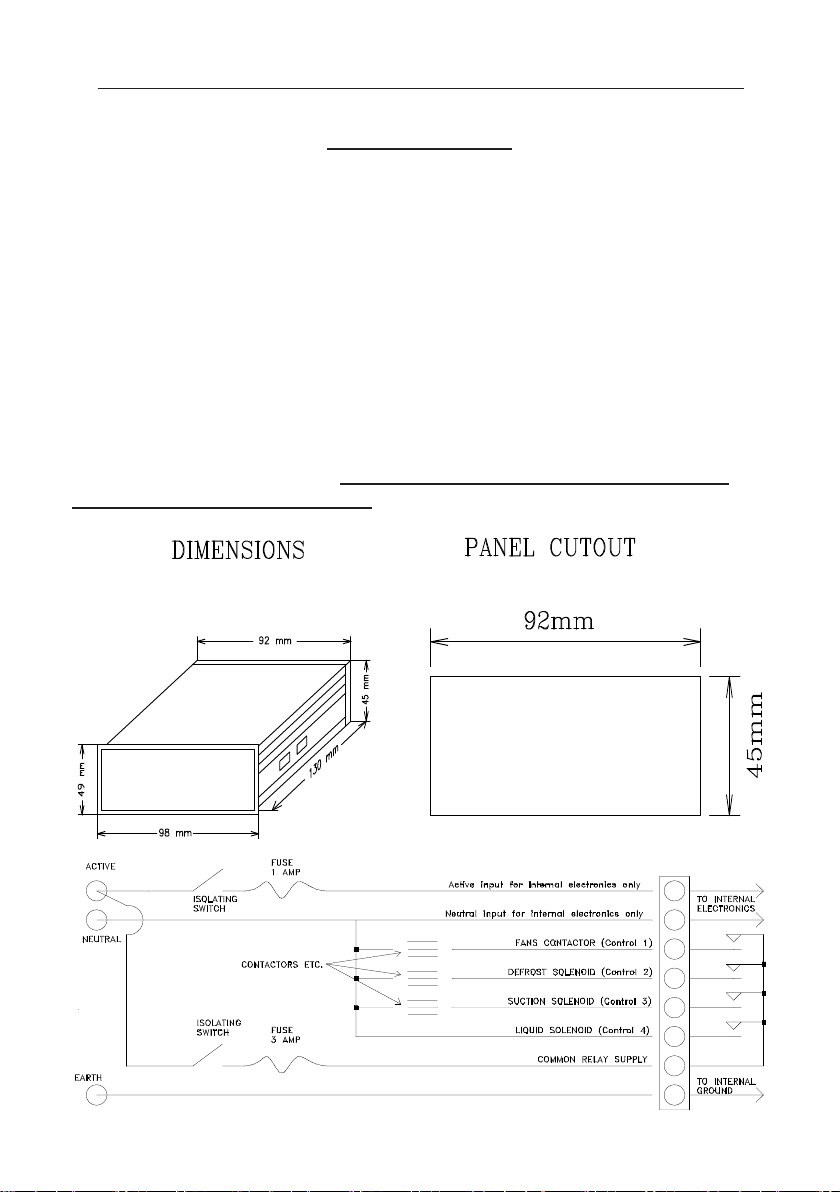
MOUNTING.
The unit should be mounted at eye level for easy viewing and access to keyboard,
using the fixing screws provided. Ensure it is in a dry area and not in direct sunlight.
POWER & SOLENOID CONNECTION.
Power to the main unit must be 240 V a.c. 50 Hz and connected to the terminals
marked A. N. E. The EARTH must be connected to the E terminal. The shield of
the sensor cable must also be connected to the earth terminal.
The supply must be a direct line from the main switch board and not an extension of other power points etc. AND MUST BE OF THE SAME PHASE AS
THE CONROL POWER SUPPLY
6
Page 7
TWITE INSTRUMENTS THERMOSTAT MODEL TD-196 OPERATING MANUAL
INSTALLATION CONT..
SENSOR INPUT CONNECTIONS.
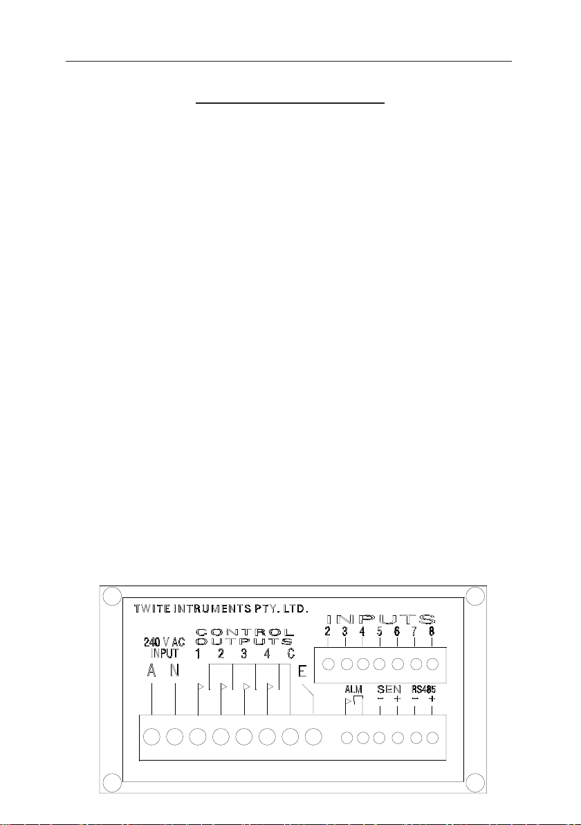
Sensor cables must be of the SHEILDED type and must not exceed 500 Metres.
Sensor cables should not run parallel or in the same duct as high voltage cables.
The shield of the sensor cable must be connected to the EARTH terminal and must
only be connected at one end, the shield must be continuous at each sensor drop.
Sensors require one wire for common (usually red) and one for positive (usually
black).
If more than one sensor is used (optional extra). The common (usually red) may be
tied to one wire which can be connected to all sensor commons. i.e.. for 8 sensors 9
wires need only be used.
The sensors (if a single sensor is used) negative wire (usually black) must be con-
nected to terminal SEN - and the positive wire (usually red) to SEN +.
Extra sensors (optional extra) positive wire (usually red) must be connected to
terminal SEN + and the negative wire (usually black) must be connected to its
corresponding channel number marked INPUTS 2 to 8 inclusive.
Sensors are numbered before shipment and are calibrated at the factory. Therefore
each sensor’s negative wire (usually black) must be connected to its’ corresponding
sensor input. For instructions on how to re calibrate sensors see CALIBRATE
SENSORS.
7
Page 8

TWITE INSTRUMENTS THERMOSTAT MODEL TD-196 OPERATING MANUAL
INSTALLATION CONT.
SENSOR POSITIONING.
The sensor (and extra sensors, optional extra) may be placed in any convenient
position keeping in mind that if more than one sensor was set to be used for controlling, the average of those sensors will the temperature used for control and will be
the temperature displayed in the normal (not scan mode) display mode while displaying the temperature.
The sensor or sensors used for control should be placed in the return air section for
cooling, and where applicable for heating.
The distance a sensor may be placed from the unit should not exceed 500 meters
The sensors must not be exposed to temperatures below -50.0 oC or above
+150.0 oC
Sensors and cables should not be fully immersed in any liquid for long periods of
time. They may be immersed for short periods for calibration purposes only. The
stainless steel sheath may be immersed in a liquid that will not corrode AISI 304
Stainless Steel.
PRINTER CONNECTION (RS485).
Up to 16 units (TD-196) can be connected to a printer (a standard EPSON ® or
compatible printer with a SERIAL interface) for printing out of temperatures at
preset times, data logged temperatures and parameter set points.
All units in the chain must have their RS485 - terminals connected
together (in parallel) and their RS485 + terminals connected together (in parallel)
using single twisted pair coaxial cable. The shield must be connected to GROUND at
one end only (not at each unit).
To connect to a printer with an RS232 port, the TD-196's + serial
output must be connected to the rs232 receive input (pin 3 on the 25 pin D connec-
tor) and the ground output/input on the TD-196 connected to the signal ground of the
printer (pin 7 on the 25 pin D connector). The pins 4 & 5 on the 25 pin D connector
must be tied (shorted) together. This type of communication is only available if all
TD-196 units are in close proximity to each other and the printer, (no more than 6
metres).
For longer distances and parrallel interface see later under Printer Communications
and Remote Display Module
8
Page 9
TWITE INSTRUMENTS THERMOSTAT MODEL TD-196 OPERATING MANUAL
INSTALLATION CONT.
ALARM OUTPUTS.
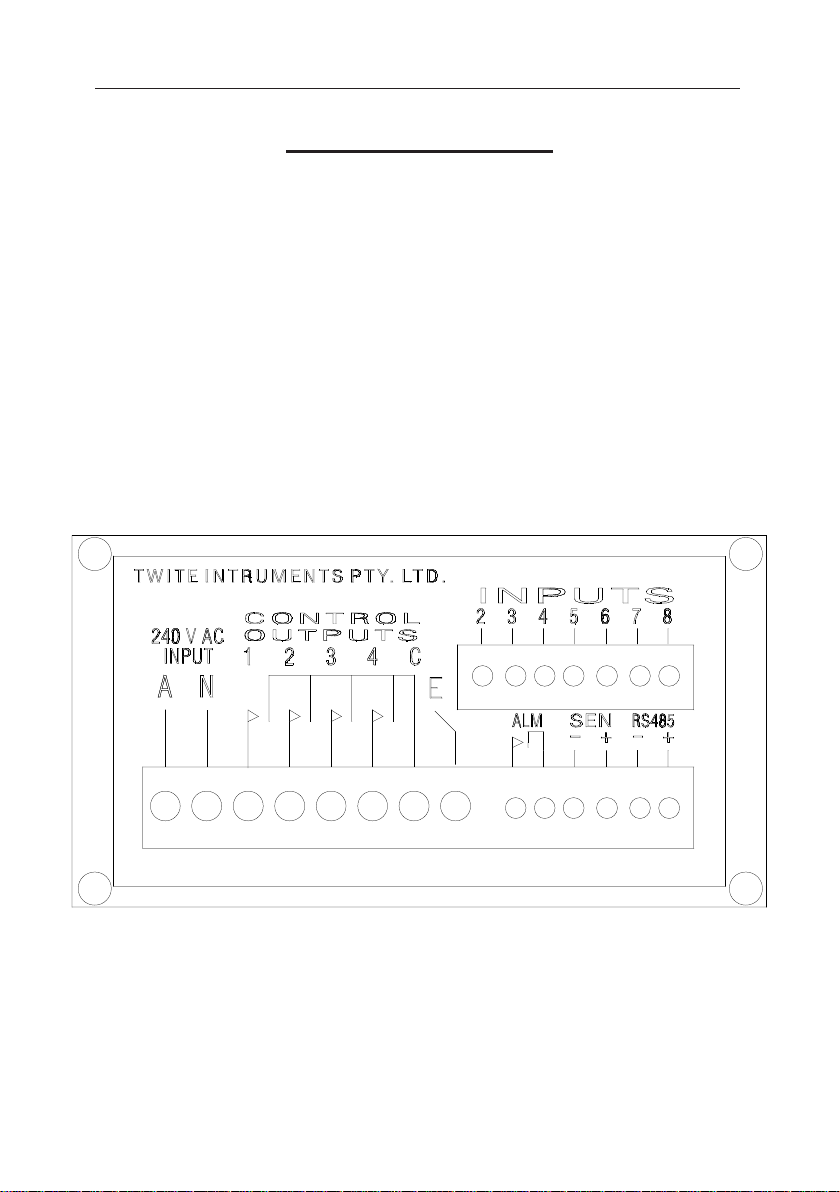
The alarm outputs (ALM terminals) are dry relay outputs which may be connected to
an external voltage source.
The relay is activated (energized) when the alarm is off, allowing an external alarm
(if it has a battery backup connected) to sound if the unit loses power.
The contact rating of the relay is 24 V d.c. 1 A.
9
Page 10
TWITE INSTRUMENTS THERMOSTAT MODEL TD-196 OPERATING MANUAL
DISPLAY FUNCTIONS
LED DISPLAY.
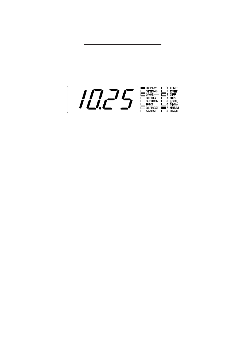
Used to display all parameters and set points etc.
1. 4 Digit Led display to display temps and all other set points etc.
2. Display LED (without the D/M/S LED lit) To display one of the D/M/S
functions press the "ENT" key, then press the s "DIS" key while
holding the "ENT" key pressed, the unit will light the D/M/S LED in
rotation, either off (this function), permanently on (for scan mode), fast
flash (maximum/minimum) or slow flash (data log display).
NOTE :- If the 8 channel option is not present the Display will indicate "Errr".
The following is if the D/M/S LED is not lit, see next page for functions
with the D/M/S LED lit :-
Indicates that one of the following is displayed depending on the LED
display on the right. To change to a different display Press the
s t "DIS" Keys.
1. Current Control temperature. The temperature
used for control, which is dependant on channels
set in CONTROL CHANNEL (Set Point No. 33)
and may be any channel or the average of selected
channels. (channel 1 only if 8 channel multiplexer
is not present).
2. The current temperature set point.
3. The current Differential setting.
4. The High Alarm temperature set point (chan 1).
5. The Low Alarm temperature set point (chan 1).
6. The current Set Point number (1 - 4) (chan 1).
7. The current time in HRS. MIN. (24 hour format).
8. The current Day & Date (day 1 = Sunday).
3. Setting LED :-
Indicates that the unit is in setting mode.
10
Page 11

TWITE INSTRUMENTS THERMOSTAT MODEL TD-196 OPERATING MANUAL
DISPLAY FUNCTIONS CONT.
LED DISPLAY CONT.
4. D/M/S LED (PRESS & HOLD THE "ENT" Key, THEN PRESS THE s
"DIS" Key with the display LED lit to cycle through these or
normal displays) :-
If OFF the display is as the previous page.
If ON continuously, the unit is in the SCAN mode. This is only available if the 8
channel option is present. The unit will scan (if the set point SCAN YES NO is set to
YES) all channels temperature, alarm set points or the current set point used (others
are for the control channel only and will not scan) as indicated by the right hand
LED on entering this mode (temps of individual sensors, not averaged first.). By
pressing the s t "DIS" Keys the unit will cycle through the channels that are set
to yes for CONNECTED, To check which parameter is displayed press the "ENT",
(the right hand LED will indicate which parameter is being displayed). To change
which parameter is displayed press the "ENT" key and hold on until the parameter
indicator LED (right hand LED'S) change from TEMP to HI/AL, LO/AL, ST/No
(cycles through each display parameter at 2 second intervals approx.). When the
desired parameter to be displayed on the right hand LED'S release the "ENT" key,
that parameter will then be displayed in the SCAN mode.
If flashing fast it is displaying Maximum / Minimum temperatures. The first to
display is the maximum (time) of channel 1. To change channels to display press the
s "DIS" key and press the t "DIS" key to toggle from maximum to the minimum
to be displayed (the decimal point will lit on digit "0", right hand digit to indicate
that the maximum time/temperature is shown). To show the HOUR:DATE of when
it happened press the "ENT" key (decimal point flashes to indicate time), press the
"ENT" key again to display the maximum/minimum temperature again.
If flashing slowly it is displaying Data Logged temperatures. The first to display is
the temperature of channel 1 (or the lowest numbered channel that was set in SET
DATA LOGGED) at the last time it was logged. To change the time of data that was
logged press the s t "DIS" keys, the display will roll around in a circular mode
displaying the data that was logged for the selected channel. To change to another
channel to display press the "ENT" key, if the channel was set to none (no data
logged) it will skip to the next channel to display.
To toggle from displaying the TEMPERATURE to HOUR:DATE press & hold the
"ENT" key Then press the t "DIS" key.
11
Page 12
TWITE INSTRUMENTS THERMOSTAT MODEL TD-196 OPERATING MANUAL
DISPLAY FUNCTIONS CONT.
LED DISPLAY CONT.
5. REFRIG LED (control 4) :-
Indicates that the Refrigeration (Liquid or output 4) Solenoid is on.
6. SUCTION LED (control 3) :-
Indicates that the Refrigeration (Suction or output 3 ) Solenoid is on.
7. FANS LED (control 1) :Indicates that the Refrigeration (fans or control 1) Solenoid is on.
8. DEFROST (control 2) :-
Indicates that the defrost (defrost or control 2) Solenoid is on.
9. ALARM LED (flashing) :-
Indicates that the ALARM is on (active). ALARM relay off..
KEY BOARD FUNCTIONS
SET KEY.
Pressing the "SET" key activates the Setting mode. If the PASSWORD is
active (password set to ON, Function No. 23), see the pass word section on page 14.
If the Password is not active (password set to OFF, Function No. 23). Then
press the s t Keys to go to the required set point to change. The set point
numbers are displayed on the 4 digit LED display. See SET POINT NUMBERS for
a listing.
When the correct set point number is displayed press the "ENT" key to select
that function. If the 8 channel option is present, some functions will require
channel selection, see SELECTING CHANNELS on page 15.
If the 8 channel option is not present, the value displayed after pressing the
"ENT" key will be the last value of that set point.
12
Page 13

TWITE INSTRUMENTS THERMOSTAT MODEL TD-196 OPERATING MANUAL
KEY BOARD FUNCTIONS CONT.
SET KEY CONT.
If more than one value is required (i.e. the 4 or 12 set points for control of cooling
or heating respectively, defrost and time etc.) the unit will request each value in turn
to be altered. After each value has been entered press the “ENT” key. The right hand
LEDS will descend to the next number showing which set point number is being set
at that time. With defrost the number 8 LED will remain lit for the first start time and
the number 1 LED will also be lit showing that the first defrost time is being set.
When setting time 8, only the number 8 LED will be lit. To have less that 8 defrosts
in one 24 hour period set the remaining start times to the same start time as the last
required defrost in that day. The unit will automatically reset the start time of the
next defrost start time to the start time of the previously set start time. After all
required values have been altered (or checked), the displays will revert to normal run
mode after the last "ENT" key press.
ENT KEY.
This key is used to enter the value selected into memory and other functions
as described. The memory will retain all set point values and data logged etc. for at
least 10 years with the power off.
s UP (DIS) KEY.
This key is used to increase the value while changing set points and to select a
channel while in the set mode and channel selection is required (optional extra) and
to change to the next display while in normal run mode and other functions as
described..
t DOWN (DIS) KEY.
This key is used to decrease the value while changing set points and to select
a channel while in the set mode and channel selection is required (optional extra) and
to change to the last display while in normal run mode & other functions as described..
NOTE:- HOLDING THE s or t KEYS DOWN WILL INCREASE OR
DECREASE THE VALUE FASTER ON SOME FUNCTIONS.
13
Page 14
TWITE INSTRUMENTS THERMOSTAT MODEL TD-196 OPERATING MANUAL
KEY BOARD FUNCTIONS CONT..
PASSWORD
USING PASSWORD.
(use SET, ENT, s and t keys)
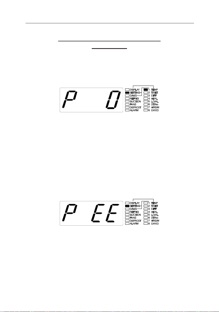
When the password is required (PASSWORD ON, function 23) the unit will request
the password when the “SET” key is pressed with the following Display.
The PASSWORD consists of 4 numbers between 0 to 9 inclusive.
To enter the first number press the "s" or "t" keys until the first number of the
password chosen is displayed, then press the “ENT” key. The display will show a 0
and the right hand LEDS will light the No. 2 led to show that the second number is
to be entered. Repeat as for the first number until all 4 numbers have been entered. If
the correct password was entered the display will show one of the functions that may
be altered, the "s" or "t" keys may be then pressed to choose the required function.
If the wrong password was entered, the display will show the following and then
revert to that which was originally displayed before any of the above keys were
pressed.
CHANGING THE PASSWORD.
The password cannot be changed (Function No. 24) if the password is not
active. To change the password, first make sure that the password is active in function No. 23. See the following individual function set point change for a full description on how to use these functions.
PASSWORD UNKNOWN.
14
See PASSWORD RESET in CALIBRATING AND DEFAULT VALUES.
Page 15
TWITE INSTRUMENTS THERMOSTAT MODEL TD-196 OPERATING MANUAL
KEYBOARD FUNCTIONS CONT..
SELECTING CHANNELS (8 CHANNEL OPTIONAL EXTRA).
FUNCTIONS THAT REQUIRE CHANNEL SELECTION ARE INDIVIDUAL FOR
EACH CHANNEL PROVIDING THAT THE 8 CHANNEL OPTION IS PRESENT.
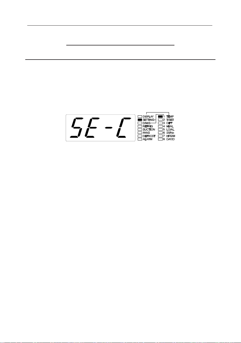
WHEN CHANNEL SELECTION IS REQUIRED THE FOLLOWING DISPLAY
WILL BE SHOWN AFTER THE FUNCTION (TO SET) HAS BEEN SELECTED
(PRESSING THE "ENT" KEY FOR THE FIRST TIME (AFTER THE PASSWORD HAS BEEN ENTERED IF REQUIRED).
To select a different channel than channel 1 press the s key, when the correct
channel is displayed (LED on that channel flashes), press the t key. When the t
key is pressed the D/M/S (green LED) will turn on to indicate that it was selected
and off to indicate that it is not selected, To select more channels or to de select a
channel, repeat the above sequence until all required channels have been selected.
The last channel selected or de selected using the t key will be the value shown on
the LED when the "ENT" key is pressed and will be the value used for the first
change even if other channels were different. If no channels were selected when the
"ENT" key is pressed, the unit will revert to its normal running display mode.
Press the "ENT" key when all channels required are selected.
After the "ENT" key is pressed, the number 1 LED (right hand LED bar) display
will show number 1 to indicate that it is set point one that will be altered. After
channel selection the s and t keys are used to alter that value for the channel/
channels that was/were selected
If the "ENT" key is pressed without changing the value with the s or t KEYS
all values will remain the same even if some of the channels set points were different
than the last channel that was selected or de selected.
15
Page 16

TWITE INSTRUMENTS THERMOSTAT MODEL TD-196 OPERATING MANUAL
KEYBOARD FUNCTIONS CONT..
FUNCTION NUMBERS
1 = Temperature set point (4 set points with time relevance).
2 = Differential set point (the amount of temp change for on/off).
3 = Set point usage Times (4 times with set point number relevance).
4 = High Alarm (4 set points with time relevance).
5 = Low Alarm (4 set points with time relevance).
6 = High Alarm Delay (delay in minutes before the alarm is on).
7 = Low Alarm Delay (delay in minutes before the alarm is on).
8 = Defrosts (sets from 1 to 8 defrosts per 24 hours).
9 = Defrost Auto On Off (allows auto defrosts or no auto defrosts).
10 = Defrost Manual On Off (allows a manual defrost, resets to off
when finished the defrost).
11 = Control On Off (allows auto control or off, all turned off).
12 = Fans Continuous or Automatic (on all the time or only while refrig).
13 = High Alarm Override (stops high alarm from activating if set to off)
14 = Low Alarm Override (stops low alarm from activating if set to off).
15 = Differential Type (whether set point is in the Middle, Top or Bot).
16 = Power On Delay (staggers start up of rooms after a power failure).
17 = Unit Number (for identifying each unit when printing).
18 = Cooling Heating (used to set the unit for Cooling or Heating mode).
19 = Time (sets the real time clock hrs,min,sec,day,date,month & year).
20 = Calibrate Real Time Clock (adjusts real time clock accuracy).
21 = Print (for setting & printing functions).
22 = Data Log (sets the time (& channels) to data log into memory).
23 = Password On Off (makes the password required active or inactive).
24 = Password Change (allows a new password to be set).
25 = Pump Down (allows the pump down of evaporator after turn off).
26 = Display Intensity (varies the brightness of the display).
27 = Daily Set Points (which set points may used for each day of week).
28 = Line Feed Yes/No (whether a unit does a line feed when printing).
29 = Channel Connected (sets which channels are present on the unit).
30 = Channel To Scan (which channels are scanned in the scan mode).
31 = Scan Time (the time between each channels display in scan mode).
32 = Scan Yes No (whether the unit is to scan or not).
33 = Control Channel (which chan is used for control and/or averages)
34 = Reset Maximum & Minimum (resets all to current time & temp).
35 = Baud rate set (sets the baud rate, stop bits = 1 and no parity).
36 = Long Term or Pull Down mode set (sets the suction sol control).
16
Page 17

TWITE INSTRUMENTS THERMOSTAT MODEL TD-196 OPERATING MANUAL
SETTING FUNCTIONS
1. TEMPERATURE SET POINTS
Sets the 4 temperature control set points associated with the 4 time set points between -50 oC. and +150 oC. If in cooling mode only one set of 4 set points. If in
heating mode there is 3 sets of 4 set points required. Control 1, 2 and 3 are available
for 3 banks of heating elements. Control 4 acts as a fans or agitator in the heating
mode and is turned on if any one or combination of the other three control relays are
on. The led's 5, 6 & 7 are lit in the heating mode to indicate which control number is
being set 5 = control 1, 6 = control 2 and 7 = control 3.
FOR COOLING
PRESS “SET”
ENTER PASSWORD IF REQUIRED
PRESS s t TO SELECT NUMBER 1
PRESS “ENT”
1 s t TO SELECT REQUIRED SET POINT 1 TEMPERATURE ON LED
PRESS “ENT”
2-4 REPEAT THIS PROCESS FOR SET POINTS 2, 3 & 4
SELECTION COMPLETE
NOTE :- These numbers represent the No. LED lit on the
FOR HEATING
PRESS “SET”
ENTER PASSWORD IF REQUIRED
PRESS s t TO SELECT NUMBER 1
PRESS “ENT”
1&5 s t TO SELECT TEMP SET POINT 1 FOR CONTROL 1 ON LED
PRESS “ENT”
2&5 s t TO SELECT TEMP SET POINT 2 FOR CONTROL 1 ON LED
PRESS “ENT”
3&5 s t TO SELECT TEMP SET POINT 3 FOR CONTROL 1 ON LED
PRESS “ENT”
4&5 s t TO SELECT TEMP SET POINT 4 FOR CONTROL 1 ON LED
PRESS “ENT”
2-4 REPEAT THIS PROCESS FOR SET POINTS 1, 2, 3 & 4 FOR CONTROL 2,
& 6-7 & 3
SELECTION COMPLETE
right hand Bar LED as the "ENT" key is pressed.
17
Page 18

TWITE INSTRUMENTS THERMOSTAT MODEL TD-196 OPERATING MANUAL
SETTING FUNCTIONS CONT..
2. DIFFERENTIAL SET POINT
Sets the Differential between +0.2 oC. and +10.0 oC. in 0.2 oC. steps.
PRESS “SET”
ENTER PASSWORD IF REQUIRED
PRESS s t TO SELECT NUMBER 2
PRESS “ENT”
1 s t TO SELECT REQUIRED DIFFERENTIAL ON LED
PRESS “ENT”
SELECTION COMPLETE
3. SET POINT USAGE TIMES.
Sets the 4 time set points associated with the control temperature set points and the
High and Low alarm temperature set points. The times can be any time of the day (in
24 hour mode) to the minute, with the following conditions. Time 1 must be the first
time after 00:00 (12 midnight) followed by time 2 etc.. Once time 1 is set the unit
will not allow time 2 to be set to an earlier time and so on for all time set points. If
two or more time set points are set to the same time, the later (if 2 and 3, time 3) will
be the time (and therefore the set point number) used from that time until the next
time set point is reached. See also DAILY SET POINTS for information on the
usage of one or more set points that can be used on any particular day of the week.
PRESS “SET”
ENTER PASSWORD IF REQUIRED
PRESS s t TO SELECT NUMBER 3
PRESS “ENT”
SELECT CHANNELS IF REQUIRED (OPTIONAL EXTRA)
1 s t TO SELECT REQUIRED SET POINT 1 TIME ON LED
PRESS “ENT”
2-4 REPEAT THIS PROCESS FOR SET POINTS 2, 3 & 4
SELECTION COMPLETE
18
Page 19

TWITE INSTRUMENTS THERMOSTAT MODEL TD-196 OPERATING MANUAL
SETTING FUNCTIONS CONT..
4. HIGH ALARM TEMPERATURE SET POINTS
Sets the 4 High alarm temperature set points associated with the 4 time set points
between -50 oC. and +150 oC.
PRESS “SET”
ENTER PASSWORD IF REQUIRED
PRESS s t TO SELECT NUMBER 4
PRESS “ENT”
SELECT CHANNELS IF REQUIRED (OPTIONAL EXTRA)
1 s t TO SELECT REQUIRED HIGH ALARM SET POINT 1 ON LED
PRESS “ENT”
2-4 REPEAT THIS PROCESS FOR SET POINTS 2, 3 & 4
SELECTION COMPLETE
5. LOW ALARM TEMPERATURE SET POINTS
Sets the 4 Low alarm temperature set points associated with the 4 time set points
between -50 oC. and +150 oC.
PRESS “SET”
ENTER PASSWORD IF REQUIRED
PRESS s t TO SELECT NUMBER 5
PRESS “ENT”
SELECT CHANNELS IF REQUIRED (OPTIONAL EXTRA)
1 s t TO SELECT REQUIRED LOW ALARM SET POINT 1 ON LED
PRESS “ENT”
2-4 REPEAT THIS PROCESS FOR SET POINTS 2, 3 & 4
SELECTION COMPLETE
19
Page 20

TWITE INSTRUMENTS THERMOSTAT MODEL TD-196 OPERATING MANUAL
SETTING FUNCTIONS CONT.
6. HIGH ALARM DELAY SET POINT.
Sets the High alarm Delay. Disables the high alarm for the time set in minutes (not
including the time the unit is doing a defrost) between 0 and 120 minutes.
PRESS “SET”
ENTER PASSWORD IF REQUIRED
PRESS s t TO SELECT NUMBER 6
PRESS “ENT”
SELECT CHANNELS IF REQUIRED (OPTIONAL EXTRA)
1 s t TO SELECT REQUIRED HIGH ALARM SET POINT 1 ON LED
PRESS “ENT”
SELECTION COMPLETE
7. LOW ALARM DELAY SET POINT.
Sets the Low alarm Delay. Disables the high alarm for the time set in minutes (not
including the time the unit is doing a defrost) between 0 and 120 minutes.
PRESS “SET”
ENTER PASSWORD IF REQUIRED
PRESS s t TO SELECT NUMBER 7
PRESS “ENT”
SELECT CHANNELS IF REQUIRED (OPTIONAL EXTRA)
1 s t TO SELECT REQUIRED LOW ALARM SET POINT 1 ON LED
PRESS “ENT”
SELECTION COMPLETE
20
Page 21

TWITE INSTRUMENTS THERMOSTAT MODEL TD-196 OPERATING MANUAL
SETTING FUNCTIONS CONT.
8. SET DEFROSTS.
1) Sets the time that the defrost solenoid is to be on during an automatic (timed)
defrost from 1 to 60 minutes in 1 minute steps.
2) Sets the time that the defrost solenoid is to be on during a manual defrost from 1
to 120 minutes in 1 minute steps.
3) Sets the defrost solenoid turn on delay after the refrigeration solenoid turns off
from 0 to 60 minutes in 1 minute steps.
4) Sets whether the fans and the suction solenoid is to be on or off (YES - NO) for
the first delay. This allows the pumping out of the Evaporator.
5) Sets the refrigeration and suction solenoids turn on delay after the defrost
solenoid turns off from 0 to 10 minutes in 1 minute steps.
6) Sets the fans solenoid turn on delay after the refrigeration and suction solenoids
turns on from 0 to 10 minutes in 1 minute steps.
7) Holds alarms & maximum/minimum from updating from 0 to 30 minutes.
8) Sets the start time of the first Defrost in a 24 hour day. (up to 8 defrost times
can be set in any one day). The first defrost start time must be the first time
required after 00:00 (12 midnight). The unit will not allow subsequent start times
to be set earlier than the previously set start time. If a time has been set for a
defrost to start before the previous defrost has finished (including the alarm hold
off time) that defrost time will be missed. There must be at least one minute
between the finish of one defrost (including the hold off time) until the start of
the next defrost. If less than 8 defrosts are required in one 24 hour period, set
the unused start times to the last defrost start time. If no automatic Defrosts are
required see DEFROST AUTO ON OFF.
21
Page 22

TWITE INSTRUMENTS THERMOSTAT MODEL TD-196 OPERATING MANUAL
SETTING FUNCTIONS CONT.
8. SET DEFROSTS CONT.
PRESS “SET”
ENTER PASSWORD IF REQUIRED
s t TO SELECT NUMBER 8
PRESS “ENT”
1 s t TO SELECT THE AUTO DEFROST TIME.
- 1/60 MINS
PRESS “ENT”
2 s t TO SELECT THE MANUAL DEFROST TIME.
- 1/120 MINS
PRESS “ENT”
3 s t TO SELECT THE DEFROST DELAY TIME.
- 0/60 MINS
4 s t TO SELECT FANS & SUCTION SOL. ON OR OFF (in the first delay)
- YES/no
PRESS “ENT”
5 s t TO SELECT THE REFRIGERATION SOLENOID TURN ON
DELAY.
- 0/10 MINS
PRESS “ENT”
6 s t TO SELECT THE FANS TURN ON DELAY.
- 0/10 MINS
PRESS “ENT”
7 s t TO SELECT DEFROST HOLD OFF DELAY.
- 0/30 MINS (disables alarm and max/min updates)
1&8 s t TO SELECT THE FIRST DEFROST START TIME.
00:00/11:59
PRESS “ENT”
2+&8 CONTINUE THE ABOVE 2 STEPS FOR THE REMAINING 7 START
TIMES
PRESS “ENT”
SELECTION COMPLETE.
22
Page 23

TWITE INSTRUMENTS THERMOSTAT MODEL TD-196 OPERATING MANUAL
SETTING FUNCTIONS CONT.
9. DEFROST AUTO OR OFF.
Sets whether automatic defrost is ON (AUTO) or OFF. ONLY USED IF
IN COOLING MODE.
PRESS “SET”
ENTER PASSWORD IF REQUIRED
s t TO SELECT NUMBER 9
PRESS “ENT”
1 s t TO SELECT “AUtO” or “OFF”
PRESS “ENT”
SELECTION COMPLETE.
10. DEFROST MANUAL ON OR OFF.
If a manual Defrost is required, set to ON. A manual defrost will commence (using
the manual defrost time set in DEFROST SET) on the next minute update. If a
automatic defrost is already active, the manual defrost will not start until the automatic defrost has finished. While a manual defrost is active any automatic defrost
will be skipped. The unit automatically sets this function to OFF on the completion
of the manual defrost (including the hold off time).
PRESS “SET”
ENTER PASSWORD IF REQUIRED
s t TO SELECT NUMBER 10
PRESS “ENT”
1 s t TO SELECT “on” or “OFF”
PRESS “ENT”
SELECTION COMPLETE.
23
Page 24

TWITE INSTRUMENTS THERMOSTAT MODEL TD-196 OPERATING MANUAL
SETTING FUNCTIONS CONT.
11. CONTROL ON OR OFF.
Sets whether control is Auto (on with temperature call) or off. If set to off all control
ceases, including defrost if active. High and low alarms are still active and may
sound if the control is left off.
PRESS “SET”
ENTER PASSWORD IF REQUIRED
s t TO SELECT NUMBER 11
PRESS “ENT”
1 s t TO SELECT “AUtO” or “OFF”
PRESS “ENT”
SELECTION COMPLETE.
12. FANS CONTINUOUS OR AUTOMATIC..
Sets whether the fans are on all the time or only on with the refrigeration and suction
solenoids. The fans turn off in either mode when in a defrost cycle.
PRESS “SET”
ENTER PASSWORD IF REQUIRED
s t TO SELECT NUMBER 12
PRESS “ENT”
1 s t TO SELECT “cont” or “AUtO”
PRESS “ENT”
SELECTION COMPLETE.
24
Page 25

TWITE INSTRUMENTS THERMOSTAT MODEL TD-196 OPERATING MANUAL
SETTING FUNCTIONS CONT.
13. HIGH ALARM ACTIVE (YES) NOT ACTIVE (NO).
Sets whether the high alarm is enabled or not for each channel.
PRESS “SET”
ENTER PASSWORD IF REQUIRED
s t TO SELECT NUMBER 13
PRESS “ENT”
1-8 PRESS s TO SELECT WHICH CHANNEL ON THE RIGHT HAND LEDS
PRESS t TO SELECT "YES" OR "no" FOR THAT CHANNEL
PRESS “ENT”
SELECTION COMPLETE.
14. LOW ALARM ACTIVE (YES) NOT ACTIVE (NO).
Sets whether the low alarm is enabled or not for each channel.
PRESS “SET”
ENTER PASSWORD IF REQUIRED
s t TO SELECT NUMBER 14
PRESS “ENT”
1-8 PRESS s TO SELECT WHICH CHANNEL ON THE RIGHT HAND LEDS
PRESS t TO SELECT "YES" OR "no" FOR THAT CHANNEL
PRESS “ENT”
SELECTION COMPLETE.
25
Page 26

TWITE INSTRUMENTS THERMOSTAT MODEL TD-196 OPERATING MANUAL
SETTING FUNCTIONS CONT.
15. DIFFERENTIAL TYPE.
This changes the position of the differential of the temperature set point to either
TOP, BOT, or MID. This means that the set point can be at the top, bottom, or
middle of the turn on and turn off temperatures.
PRESS “SET”
ENTER PASSWORD IF REQUIRED
s t TO SELECT NUMBER 15
PRESS “ENT”
1 s t TO SELECT “toP”, “bot” or “nid”
PRESS “ENT”
SELECTION COMPLETE.
TOP :-
TURN ON SET
POINT
DIFF'L
TURN OFF
BOTTOM :-
POINT
MIDDLE :-
SET POINT
26
TURN ON
DIFF'L
TURN OFF SET
TURN ON
DIFF'L
TURN OFF
Page 27

TWITE INSTRUMENTS THERMOSTAT MODEL TD-196 OPERATING MANUAL
SETTING FUNCTIONS CONT.
16. POWER ON DELAY.
Sets the Delay time (in seconds) that a unit can turn on after there has been a power
failure. Allows rooms to turn on at different times to stop all rooms turning on at
once after a power failure.
PRESS “SET”
ENTER PASSWORD IF REQUIRED
PRESS s t TO SELECT NUMBER 16
PRESS “ENT”
1 s t TO SELECT DELAY FROM 0 TO 600 SECONDS ON LED
PRESS “ENT”
SELECTION COMPLETE
17. UNIT NUMBER.
Sets the unit number for printing so that each unit has a unique number between 1
and 16 inclusive.
PRESS “SET”
ENTER PASSWORD IF REQUIRED
PRESS s t TO SELECT NUMBER 17
PRESS “ENT”
1 s t TO SELECT UNIT NUMBER FROM 1 TO 16 INCLUSIVE ON LED
PRESS “ENT”
SELECTION COMPLETE
27
Page 28

TWITE INSTRUMENTS THERMOSTAT MODEL TD-196 OPERATING MANUAL
SETTING FUNCTIONS CONT.
18. COOLING OR HEATING.
Sets whether the unit is to be used for Cooling or Heating. The relays are always ON
(active) whether cooling or heating. In the Heating mode the first three control
(relays) outputs can be used for different heating banks at different temperatures.
PRESS “SET”
ENTER PASSWORD IF REQUIRED
s t TO SELECT NUMBER 18
PRESS “ENT”
1 s t TO SELECT “COOL” or “HEAt”
PRESS “ENT”
SELECTION COMPLETE.
19. SET REAL TIME CLOCK.
Sets the Real Time Clock. Each time element, (i.e.. hours, minutes, seconds, day,
date, month, year) is set individually.
PRESS “SET”
ENTER PASSWORD IF REQUIRED
s t TO SELECT NUMBER 19
PRESS “ENT”
1 s t TO SELECT HOUR (00 - 23)
PRESS “ENT”
2 s t TO SELECT MINUTES (00 - 59)
PRESS “ENT”
3 s t TO SELECT SECONDS (00 - 59)
PRESS “ENT”
4 s t TO SELECT DAY (1 - 7 SUNDAY = 1)
PRESS “ENT”
5 s t TO SELECT DATE (1 - 31)
PRESS “ENT”
6 s t TO SELECT MONTH (1 - 12)
PRESS “ENT”
7 s t TO SELECT YEAR (00 - 99)
PRESS “ENT”
SELECTION COMPLETE.
28
Page 29

TWITE INSTRUMENTS THERMOSTAT MODEL TD-196 OPERATING MANUAL
SETTING FUNCTIONS CONT.
20. CALIBRATE REAL TIME CLOCK.
Adjusts the Real Time Clock in steps between -30 and +30. 1 step each. 1 step =
5.34 seconds (approx.) per month. To check clock, set to the correct time with the
calibrate set to 0 and check variation after 1 week. Adjust the calibrate value accordingly.
PRESS “SET”
ENTER PASSWORD IF REQUIRED
s t TO SELECT NUMBER 20
PRESS “ENT”
1 s t TO SELECT REQUIRED No. FROM -30 TO +30 ON LED.
PRESS “ENT”
SELECTION COMPLETE.
21. PRINT.
Used for the following Print functions :- 1 = Print at preset times. 2 = Print Set point
parameters, 3 = data logged print and 4 = maximum and minimum.
If print at preset times is selected, it may be set to print every 15, 30, 60, 120
minutes or 1 to 4 times per day, or none (no print at preset times)
PRESS “SET”
ENTER PASSWORD IF REQUIRED
s t TO SELECT NUMBER 21
PRESS “ENT”
SELECT CHANNELS IF REQUIRED (OPTIONAL EXTRA)
1 s t TO SELECT "PSt" "PSP" "dLo" "Pnn" (preset times, parameter set
points, data logged and maximum/minimum).
PRESS “ENT”
If parameter set points, data logged or maximum/minimum was selected the
data will be sent to the RS485 port. NOTE :- at least one channel must be
selected if selecting parameters to print but all channels will be printed if the 8
channel option is present.
The unit will send the above data if no other unit is currently printing after a
delay of its own unit identity number in 1/3rd. seconds or after the same delay
after the other units have stopped printing. The unit will return to its normal
running mode display after the above two if selected.
If print at preset times was selected continue to select when to print.
29
Page 30

TWITE INSTRUMENTS THERMOSTAT MODEL TD-196 OPERATING MANUAL
SETTING FUNCTIONS CONT.
21. PRINT CONT.
THE VALUE SHOWN WILL BE THE CURRENT VALUE OF THE PRINT
AT PRESET TIMES (either “1to4", "15", "30", "60", "120", "0"
(none)).
s t TO SELECT “1to4", "15", "30", "60", "120", "0" (none)
PRESS “ENT”
If any except "1to4" was selected SELECTION COMPLETE
If "1- 4" was selected, (led No. 1 will also light to indicate that more is to be
entered).
1-5 s t TO SELECT THE TIME OF DAY FOR THE FIRST PRINT TIME.
00:00 TO 23:59
PRESS “ENT”
REPEAT FOR THE OTHER 3 TIMES TO PRINT IN THE 24 HOUR PE-
RIOD. IF LESS THAN 4 TIMES ARE REQUIRED, SET THE RE
MAINING TIMES TO THE SAME TIME AS THE LAST TIME
REQUIRED. EACH TIME SELECTED MUST BE LATER OR EQUAL
TO THE PREVIOUS TIME SELECTED.
SELECTION COMPLETE
30
NOTE :-
THE 4 TIMES OF DAY ARE RELEVANT FOR ALL CHANNELS
THAT ARE SET TO PRINT 1 TO 4 TIMES EACH 24 HOUR
PERIOD. I.E.. ONLY ONE SET OF 4 TIMES CAN BE SET AND
ALL CHANNELS SET TO 1 TO 4 USE THESE TIMES.
Page 31

TWITE INSTRUMENTS THERMOSTAT MODEL TD-196 OPERATING MANUAL
SETTING FUNCTIONS CONT.
22. DATA LOGGING.
Used to place temperature data into ram for displaying or printing at a later date.
PRESS “SET”
ENTER PASSWORD IF REQUIRED
s t TO SELECT NUMBER 22
PRESS “ENT”
SELECT CHANNELS IF REQUIRED (OPTIONAL EXTRA)
1 s t TO SELECT “1- 4", "15", "30", "60", "120", "0" (none)
PRESS “ENT”
If any except "1- 4" was selected SELECTION COMPLETE
If "1- 4" was selected
2-5 s t TO SELECT THE TIME OF DAY FOR THE FIRST PRINT TIME.
00:00/11:59
PRESS “ENT”
REPEAT FOR THE OTHER 3 TIMES TO LOG IN THE 24 HOUR PERIOD. IF LESS THAN 4 TIMES ARE REQUIRED, SET THE REMAINING
TIMES TO THE SAME TIME AS THE LAST TIME REQUIRED.
SELECTION COMPLETE
NOTE :-
THE 4 TIMES OF DAY ARE RELEVANT FOR ALL CHANNELS
THAT ARE SET TO PRINT 1 TO 4 TIMES EACH 24 HOUR
PERIOD. I.E.. ONLY ONE SET OF 4 TIMES CAN BE SET AND
ALL CHANNELS SET TO 1 TO 4 USE THESE TIMES.
31
Page 32

TWITE INSTRUMENTS THERMOSTAT MODEL TD-196 OPERATING MANUAL
SETTING FUNCTIONS CONT.
23. PASSWORD ON OR OFF.
Sets whether the Pass word is required to enable altering of set points etc.
PRESS “SET”
ENTER PASSWORD IF REQUIRED
s t TO SELECT NUMBER 23
PRESS “ENT”
1 s t TO SELECT “on” or “OFF”
PRESS “ENT”
SELECTION COMPLETE.
24. CHANGE PASSWORD.
Sets the new password (4 numbers between 0 - 9 inclusive)
NOTE :- IF THE PASS WORD IS INACTIVE (OFF) THE PASS-
WORD CANNOT BE CHANGED. IF CHANGE PASSWORD IS
SELECTED WITH THE PASSWORD REQUIRED IS SET TO
"OFF" THE UNIT WILL RETURN TO NORMAL RUNNING
MODE WHEN THE "ENT" KEY IS PRESSED.
TO CHANGE THE PASS WORD FIRST MAKE SURE THAT THE
FUNCTION "PASSWORD ON OR OFF" IS SET TO "ON".
THIS ENSURES THAT THE PASS WORD IS REQUIRED BE-
FORE CHANGING IT TO A DIFFERENT NUMBER.
PRESS “SET”
ENTER PASSWORD
PRESS s t TO SELECT NUMBER 24
PRESS “ENT”
1 s t TO SELECT REQUIRED FIRST PASSWORD NUMBER ON LED
PRESS “ENT”
2-4 REPEAT THIS PROCESS FOR PASSWORD NUMBERS 2, 3 & 4
SELECTION COMPLETE
32
Page 33

TWITE INSTRUMENTS THERMOSTAT MODEL TD-196 OPERATING MANUAL
SETTING FUNCTIONS CONT.
25. PUMP DOWN SET POINT.
Sets the pump down between 0 - 1800 seconds. This leaves the fans and suction
solenoids on for the set time in seconds after the control (refrigeration solenoid) has
turned off. Allows for the pumping out of the evaporator.
PRESS “SET”
ENTER PASSWORD IF REQUIRED
PRESS s t TO SELECT NUMBER 25
PRESS “ENT”
1 s t TO SELECT REQ. PUMP DOWN TIME IN SECONDS ON LED
PRESS “ENT”
SELECTION COMPLETE.
26. DISPLAY INTENSITY.
Sets the brightness of the display from 1 - 15 inclusive.
PRESS “SET”
ENTER PASSWORD IF REQUIRED
PRESS s t TO SELECT NUMBER 26
PRESS “ENT”
1 s t TO SELECT REQUIRED BRIGHTNESS ON LED (8 recommended).
PRESS “ENT”
SELECTION COMPLETE.
33
Page 34

TWITE INSTRUMENTS THERMOSTAT MODEL TD-196 OPERATING MANUAL
SETTING FUNCTIONS CONT.
27. DAILY SET POINTS.
Sets which set points 1,2,3,4 may be used on each day of the week. If no set points
were selected for a particular day, set point 1 will be used.
PRESS “SET”
ENTER PASSWORD IF REQUIRED
PRESS s t TO SELECT NUMBER 27
PRESS “ENT”
SELECT CHANNELS IF REQUIRED (OPTIONAL EXTRA)
1 s TO SELECT "n" for not to use that set point number for that day or yes
for that set point number for that day. If pressed again it
will toggle between "n" (not to use) and the set point
number (to use). The set point number that is flashing is
the set point number that is being enabled or disabled for
that day (shown on the right hand LEDS, No. 1 =
SUNDAY).
PRESS t TO SELECT ANOTHER SET POINT FOR THE CURRENT DAY
The t key, if pressed again will rotate through all set
points for the current day (the selected one will flash).
PRESS “ENT”
2-7 REPEAT THE ABOVE STEPS FOR ALL 7 DAYS OF THE WEEK
THE FIRST DAY ON ENTERING THIS FUNCTION WILL BE DAY 1
SUNDAY.
SELECTION COMPLETE.
34
Page 35

TWITE INSTRUMENTS THERMOSTAT MODEL TD-196 OPERATING MANUAL
SETTING FUNCTIONS CONT.
28. LINE FEED YES OR NO.
Sets whether this unit is to send a line feed to the printer after it has sent its temperature data, if printing at preset times. This should be set to yes if this unit is the last
one in the system (largest unit identity number) or is the one printing with the
smallest print interval. Each unit prints its data (print at preset times) at its own
position on a line therefore the unit that prints last on a line should send a line feed
to the printer, otherwise printing may be over printed in some cases. The unit that
sends the line feed also sends its time of day before it sends its temperature and line
feed.
NOTE :- If a unit is set to do a line feed and time it will send its time and
data, then send a page break and heading the first print time after it has been set to
do a line feed in this function. This allows the setting up of the printer and paper for
page breaks etc.
PRESS “SET”
ENTER PASSWORD IF REQUIRED
s t TO SELECT NUMBER 28
PRESS “ENT”
1 s t TO SELECT “YES” or “no”
PRESS “ENT”
SELECTION COMPLETE.
29. CHANNELS CONNECTED.
Selects the channels that are connected. If a channel is set to not connected, the unit
will not allow any function to operate on that channel.
PRESS “SET”
ENTER PASSWORD IF REQUIRED
s t TO SELECT NUMBER 29
PRESS “ENT”
1-8 PRESS s TO SELECT WHICH CHANNEL ON THE RIGHT HAND LEDS
PRESS t TO SELECT "YES" OR "no" FOR THAT CHANNEL
PRESS “ENT”
SELECTION COMPLETE.
35
Page 36

TWITE INSTRUMENTS THERMOSTAT MODEL TD-196 OPERATING MANUAL
SETTING FUNCTIONS CONT.
30. CHANNELS TO SCAN.
Selects channels to scan when in scan mode. If a channel is set to NOT CONNECTED it will not be scanned even if it set to scan.
PRESS “SET”
ENTER PASSWORD IF REQUIRED
s t TO SELECT NUMBER 30
PRESS “ENT”
1-8 PRESS s TO SELECT WHICH CHANNEL ON THE RIGHT HAND LEDS
PRESS t TO SELECT "YES" OR "no" FOR THAT CHANNEL
PRESS “ENT”
SELECTION COMPLETE.
31. SCAN TIME
Sets the time between channel scan from 1 to 50.
i.e.. 50 = 10 sec, 25 = 5, 1 = 1/4 sec approx.
PRESS “SET”
ENTER PASSWORD IF REQUIRED
PRESS s t TO SELECT NUMBER 31
PRESS “ENT”
1 s t TO SELECT REQUIRED SCAN TIME FROM 1 - 50 INC. ON LED
PRESS “ENT”
SELECTION COMPLETE
32. SCAN YES OR NO
Sets whether the unit will scan or not (scans all required temperatures, high and low
alarms and set point used) if the display is displaying the relevant data.
PRESS “SET”
ENTER PASSWORD IF REQUIRED
PRESS s t TO SELECT NUMBER 32
PRESS “ENT”
1 s t TO SELECT "YES" OR "no" ON LED
PRESS “ENT”
SELECTION COMPLETE
36
Page 37

TWITE INSTRUMENTS THERMOSTAT MODEL TD-196 OPERATING MANUAL
SETTING FUNCTIONS CONT.
33. CONTROL CHANNEL.
Sets which channel is used for the control channel (i.e. the control may be on any
single channel or the average of selected channels). If a channel was selected for
control and was set to NOT CONNECTED, the control will not operate. If average
of selected channels was selected (more than one channel set to "yes") and one of
the selected channels was set to NOT CONNECTED, that channel will not be used
in the averaging process. If average of selected channels was selected (more than one
channel set to "yes") and one or more channel's was/were in over range (fault on
sensor cable or faulty sensor), the unit will turn off all controls.
PRESS “SET”
ENTER PASSWORD IF REQUIRED
s t TO SELECT NUMBER 33
PRESS “ENT”
1-8 PRESS s TO SELECT WHICH CHANNEL ON THE RIGHT HAND LEDS
PRESS t TO SELECT "YES" OR "no" FOR THAT CHANNEL
PRESS “ENT”
SELECTION COMPLETE.
34. RESET MAXIMUM MINIMUM
Resets the currently stored Maximum and Minimum to the current temperature and
the current time.
PRESS “SET”
ENTER PASSWORD IF REQUIRED
s t TO SELECT 34
PRESS “ENT”
SELECT CHANNELS IF REQUIRED (OPTIONAL EXTRA)
PRESS “ENT”
SELECTION COMPLETE.
37
Page 38

TWITE INSTRUMENTS THERMOSTAT MODEL TD-196 OPERATING MANUAL
SETTING FUNCTIONS CONT.
35. BAUD RATE SETTING.
Sets the BAUD rate for the RS485 communications between 110, 300, 1200, 2400,
4800 and 9600. The STOP bit is set at 1 STOP BIT and the PARITY is set at
NONE. The stop bit and parity cannot be changed. The printer connected to the units
must be set to the same parameters as all TD-196 units.
PRESS “SET”
ENTER PASSWORD IF REQUIRED
PRESS s t TO SELECT NUMBER 35
PRESS “ENT”
s t TO SELECT REQUIRED BAUD RATE ON LED
PRESS “ENT”
SELECTION COMPLETE.
36. LONG TERM OR PULL DOWN MODE SETTING.
Sets whether the Suction solenoid is on during refrigeration or not. The long term
mode is used for systems that have a back pressure regulator installed and the suction
solenoid is only turned on (pull down mode) when maximum refrigeration is required.
NOTE :- The suction solenoid is still turned on at the required times
during a Defrost cycle and during the Pump Down Cycle
(if enabled) with the fans relay.
PRESS “SET”
ENTER PASSWORD IF REQUIRED
PRESS s t TO SELECT NUMBER 36
PRESS “ENT”
s t TO SELECT EITHER "PU-d" (pull down, suction solenoid on) or
"LO-t" (long term, suction solenoid off)
PRESS “ENT”
SELECTION COMPLETE.
38
Page 39

TWITE INSTRUMENTS THERMOSTAT MODEL TD-196 OPERATING MANUAL
SETTING FUNCTIONS CONT.
39
Page 40

TWITE INSTRUMENTS THERMOSTAT MODEL TD-196 OPERATING MANUAL
PRINTER COMMUNICATIONS
Up to 16 units (TD-196) can be connected to a printer for printing out
of temperatures at preset times, data logged temperatures and parameter set points.
All units in the chain must have their RS485 - terminals connected
together (in parallel) and their RS485 + terminals connected together (in parallel)
using single twisted pair coaxial cable. The shield must be connected to GROUND at
one end only (not at each unit).
To connect to a printer with an RS232 port, the TD-196's + serial
output must be connected to the rs232 receive input (pin 3 on the 25 pin D connec-
tor) and the ground output/input on the TD-196 connected to the signal ground of the
printer (pin 7 on the 25 pin D connector). The pins 4 & 5 on the 25 pin D connector
must be tied (shorted) together. This type of communication is only available if all
TD-196 units are in close proximity to each other and the printer, (no more than 6
metres).
When using the Remote Display Module the distance may be extended
to 500 metres between all units and the Remote Display unit. The printer is connected to the remote display unit via a standard parallel printer cable, and does not
require RS232 interface. For more information on the Remote Display Module, see
REMOTE DISPLAY.
All units must be set to have a unique identity number (1 - 16 inclu-
sive). As each unit prints its temperature (at preset times) it places its data in its
relative position (compared to its unit number) on the line of an A4 page. The unit
that is set to do a LINE FEED also prints the current time at the start of the line
before it prints its temperature on its relevant position then sends a line feed to allow
the next lot of temperatures to print at the next time. The unit that has the largest
number (unit identity) should be set to send the line feed, as the unit number determines the time when the unit is allowed to print after the RS485 line becomes
available.
When printing parameter set points, data logged or maximum and
minimum (see PRINT) the unit will send a line feed and a carriage return then its
own identity number plus time and date before it sends its data.
If the 8 channel option is installed on any unit in the chain, these units
will always send a line feed and its identity number if more than one sensor (or one
sensor other than channel one) temperature is to be sent.
The unit that sends the line feed also counts line feeds as they are sent
to the printer and will send a form feed after 56 line feeds have been sent to the
printer. Then this unit will send a heading with channel numbers etc. for the beginning of a new page. See Setting LINE FEED YES/NO for more information on
page breaks and headings also.
40
Page 41

TWITE INSTRUMENTS THERMOSTAT MODEL TD-196 OPERATING MANUAL
CALIBRATING AND DEFAULT VALUES
NOTE :- FOR ALL FUNCTIONS UNDER CALIBRATING AND
DEFAULT VALUES, CAUTION MUST BE TAKEN AS THESE
FUNCTIONS CAN CHANGE VALUES DRAMATICALLY, PAR-
TICULARLY HIGH AND LOW CALIBRATION VALUES.
TO ENTER INTO ONE OF THE FOLLOWING FUNCTIONS
DO EITHER OF THE BELOW OPERATIONS
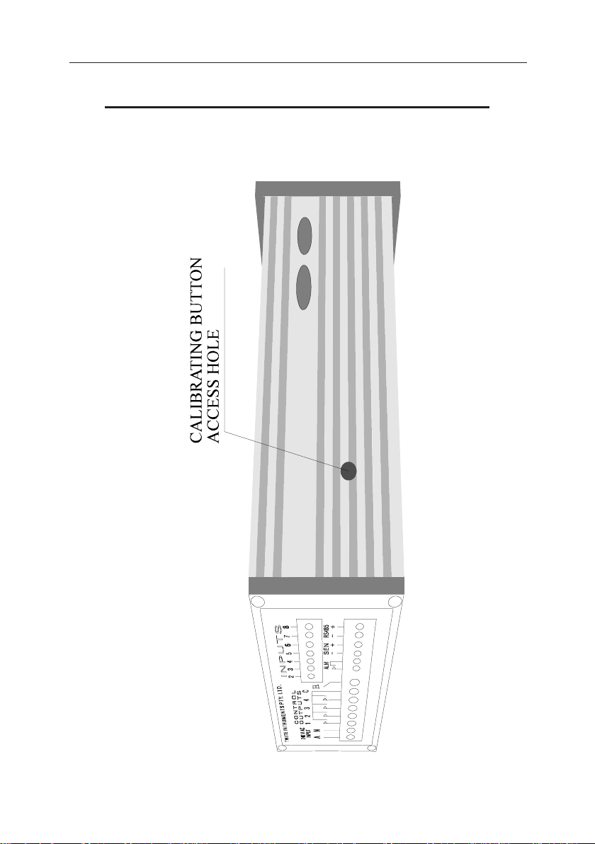
1 :- PRESS THE CAL BUTTON (USING ONLY LIGHT PRESSURE LOCATED ON THE RIGHT HAND SIDE OF THE UNIT
LOOKING FROM THE BACK THROUGH THE ACCESS HOLE
IN THE SIDE OF THE UNIT AS SHOWN FOLLOWING). WHEN
THIS BUTTON IS PRESSED THE DISPLAY WILL SHOW "d 1"
INDICATING THAT FUNCTION NUMBER ONE MAY BE USED
AS LISTED IN THE FOLLOWING TABLE. TO CHANGE TO A
DIFFERENT FUNCTION PRESS THE "UP' OR "DOWN" KEY
FROM 1 TO 10 TO SELECT THE FUNCTION. WHEN THE
CORRECT NUMBER IS DISPLAYED FOR THE REQUIRED
FUNCTION PRESS THE "ENT" KEY. AFTER THE "ENT" KEY
HAS BEEN PRESSED USE THE FOLLOWING DESCRIPTIONS
TO CONTINUE TO USE THAT FUNCTION.
2 :- TURN THE UNIT OFF AND PRESS AND HOLD THE
INDICATED KEYS (FOR THE FUNCTION REQUIRED), AND
WHILE THE KEYS ARE HELD ON (PRESSED), APPLY THE
POWER TO THE UNIT. THEN USE THE FOLLOWING DE-
SCRIPTIONS TO CONTINUE TO USE THAT FUNCTION.
FUNCTION NUMBERS FOR THE CAL BUTTON PRESSED (OPTION 1)
1 = Calibrate Values Check & Alter.
2 = Calibration Values Update.
3 = Test Displays.
4 = Memory (Ram) Test.
5 = Reset Data Logging.
6 = Reset Password.
7 = Set Parameters To a Default Value.
8 = Kick Start The Real Time Clock.
9 = Calibrate Sensors.
10 = Start Up Default Values.
41
Page 42
TWITE INSTRUMENTS THERMOSTAT MODEL TD-196 OPERATING MANUAL
CALIBRATION AND DEFAULT VALUES CONT.
42
Page 43

TWITE INSTRUMENTS THERMOSTAT MODEL TD-196 OPERATING MANUAL
CALIBRATION AND DEFAULT VALUES CONT.
WARNING : MAKE SURE CALIBRATION VALUES ARE
KNOWN BEFORE DOING THE FOLLOWING FUNCTIONS,
OTHERWISE THE SENSORS MAY REQUIRE RE CALIBRATION IF THE WRONG CHANNELS ARE RESET OR ALTERED BY MISTAKE.
CALIBRATE VALUES CHECK & ALTER (1) “SET” & “ENT” &
“s” KEYS
This is used to read and manually alter the high and low offset values for each
sensor. It is recommended that the values for each channel be written down and kept
in case of the data being lost.
If the 8 channel option is present do the following to select the required channel
number. If not present skip the next paragraph.
To select a channel number Press the “s” key to cycle through the channel numbers
(1 - 8 on the right hand LED indicators). The value displayed will be the high value
of the displayed channel. Pressing the "ENT" key will toggle from displaying the
high value and displaying the low value of the selected channel. If no alteration is
necessary press the "SET" key while the "CAL" switch is depressed, the display
will then show "done", press the "ENT" key to reset the unit for normal operation,.
If alteration is required on a channel (only one channel at a time can be altered)
Press the “t” key to select that channel.
The Right hand LED indicator will now show No. 1 (or 2 depending on which was
selected with the "ENT" key, only if the 8 channel multiplexer is present) lit,
indicating that the HIGH (or LOW depending on which was selected with the "ENT"
key, only if the 8 channel multiplexer is present) calibration value may be altered,
Press the “s” & “t” keys to alter this value.
To change from HIGH to LOW calibration value to alter, Press the “ENT” key, the
No. 2 LED on the right hand LED indicators will now be lit to show that the LOW
value may now be changed. The “ENT” key, may be pressed to change from HIGH
value to LOW value to alter at any time (the right hand LED indicators will toggle
from No. 1 to No. 2 to indicate whether the HIGH (No. 1 LED) or LOW (No. 2 LED)
value is active).
43
Page 44

TWITE INSTRUMENTS THERMOSTAT MODEL TD-196 OPERATING MANUAL
CALIBRATION AND DEFAULT VALUES CONT.
CALIBRATE VALUES CHECK & ALTER (1) “SET” & “ENT” &
“s” KEYS CONT.
When the correct values have been entered (make sure to keep a copy of the correct
values in case of memory loss) press the “SET” key while the "CAL" switch is
depressed, the display will then show "done", press the "ENT" key again to reset
the unit for normal operation.
IF ANY VALUES WERE CHANGED BY THE ABOVE OPERATION. THE UNIT
MAY GIVE AN ERROR MESSAGE OF "C-CA' TO INFORM OF AN ERROR IN
CALIBRATION VALUES. TO RECTIFY THIS IT WILL BE NECESSARY TO
ENTER THE CALIBRATION VALUES INTO OTHER SECTIONS OF RAM FOR
THE CHECK SUM AND CORRUPTION TESTING.
TO DO THIS, USE THE "CALIBRATION VALUES UPDATE" FOLLOWING.
CALIBRATION VALUES UPDATE (2) “SET” & “ENT” & “t”
KEYS.
If an error message appears "C-CA" it means that the calibration values have been
altered or are corrupt. To rectify this, first check that all calibration values are
checked by using the previous function "CALIBRATE VALUES CHECK & ALTER". After doing this, use this function to update all values for the check sum and
corruption testing in the unit. When this function is first entered the display will show
"CALS" to indicate that the "CAL" switch must be pressed, press the "CAL"
switch and then the display will show "C U" to indicate that the update has been
done, press the "ENT" key to reset the unit and resume normal operation.
TEST DISPLAYS (3) “ENT” & “s” KEYS
All LED displays and Indicators will be lit. If some segments are not lit, those
segments will be faulty and service is required.
Press the “ENT” key for reset and normal operation.
MEMORY (RAM) TEST (4) “ENT” & “t” KEYS
If the memory test was successful the LED will display "r O". If the RAM was
found to be faulty the display will display "A EE", and if the CPU RAM was found
to be faulty "C EE".
Press the “ENT” key for reset and normal operation.
44
Page 45

TWITE INSTRUMENTS THERMOSTAT MODEL TD-196 OPERATING MANUAL
CALIBRATION AND DEFAULT VALUES CONT.
RESET DATA LOGGING (5) “SET” & “t” KEYS
This deletes all data that has been logged in memory.
LED shows “d r”.
Press the “ENT” key for reset and normal operation.
RESET PASSWORD (6) “SET” & “s” KEYS
This puts 4 "1"'s into the PASSWORD RAM, i.e. “1111”. Used if password is
forgotten or corrupt.
LED shows "P r"
Press the “ENT” key for reset and normal operation.
SET PARAMETERS TO A DEFAULT VALUE (7) “s” & “t” KEYS
Sets all Parameters to a Default Value, but unlike the Start up Default, the Clock
does not Kick Start and the calibration values are not changed.
LED shows "d P".
Press the “ENT” key for reset and normal operation.
KICK START THE REAL TIME CLOCK (8) “SET” & “ENT” KEYS
This starts the Real Time Clock if the chip has been replaced or the clock will not
run because of corrupt data fed to the clock address etc..
If the unit will not run on power up KICK START the REAL TIME CLOCK as all
functions of the program rely on the real time clock counting up in time.
The LED shows “C S”. Wait for at least 10 seconds before resetting the unit with
this function as the clock takes a while to begin to function.
Press the “ENT” key for reset and normal operation.
45
Page 46

TWITE INSTRUMENTS THERMOSTAT MODEL TD-196 OPERATING MANUAL
CALIBRATION AND DEFAULT VALUES CONT.
CALIBRATE SENSORS (9) “ENT” & “s” “t” KEYS
This determines the high and low calibration offset values to ensure accurate temperature calibration.
The offsets are stored into non volatile RAM for use in software calibration during
the normal run mode of the unit.
NOTE :- DO THIS BEFORE DOING THIS FUNCTION.
THIS IS REQUIRED ONLY IF THE 8 CHANNEL OPTION IS PRESENT.
IF THE OPTION IS NOT PRESENT SKIP THE CHANNEL SELECTION
AND GO TO THE FOLLOWING PAGE.
PRESS “SET”
ENTER PASSWORD IF REQUIRED
s t TO SELECT “29 - CHANNELS CONNECTED”
PRESS “ENT”
SELECT OR DESELECT CHANNELS AS REQUIRED ENSURING ONLY
CHANNELS TO BE CALIBRATED REMAIN CONNECTED. BY PRESS
ING THE s KEY TO CYCLE THROUGH THE CHANNEL NUM-
BERS ON THE RIGHT HAND LED INDICATOR, AND PRESS THE t
KEY TO SELECT OR DE SELECT EACH REQUIRED CHANNEL. "YES" = THAT CHANNEL IS SELECTED (CON-
NECTED) AND "no" = THAT CHANNEL IS NOT SELECTED
(NOT CONNECTED).
PRESS “ENT” WHEN ALL CHANNELS TO BE CALIBRATED ARE
SELECTED.
NOTE :- ALL SENSORS THAT ARE SET TO CONNECTED
WILL HAVE THEIR VALUES CHANGED. THIS WILL CAUSE
THE WRONG OFFSET VALUES TO BE WRITTEN TO THE
MEMORY IF THE SENSORS THAT ARE SET TO CONNECTED
ARE NOT IN THE CALIBRATION PROCEDURE.
46
Page 47

TWITE INSTRUMENTS THERMOSTAT MODEL TD-196 OPERATING MANUAL
CALIBRATION AND DEFAULT VALUES CONT.
CALIBRATE SENSORS (9) “ENT” & “s” “t” KEYS CONT.
Place Sensors to be calibrated into a stirred bath at 0.00 oC and leave to stabilize for
approx. 5 minutes. The display will be the first sensors value that is set to CON-
NECTED.
PRESS “t” while the "CAL" button is depressed, (if the "CAL" button is
not held pressed the unit will give a double beep and the value will not be updated
into E2PROM), if only one beep is heard the value will have been updated into the
E2PROM correctly for the channels set to "connected".
Place Sensors to be calibrated into a stirred bath at 100.00 oC and leave to stabilize
for approx. 5 minutes. The display will be the first sensors value that is set to
CONNECTED.
PRESS “s” while the "CAL" button is depressed, (if the "CAL" button is not
held pressed the unit will give a double beep and the value will not be updated into
E2PROM), if only one beep is heard the value will have been updated into the
E2PROM correctly for the channels set to "connected".
Press the “ENT” key for the values to take affect and reset the unit for normal
operation.
MAKE SURE A COPY OF THE HIGH AND LOW VALUES ARE KEPT FOR
ENTERING INTO MEMORY. IF THEY ARE LOST DUE TO MEMORY
LOSS ETC. THIS MAY ALSO BE DONE USING THE CHECK AND ALTER
CALIBRATION FUNCTION PREVIOUSLY DESCRIBED.
START UP DEFAULT VALUES (10) “SET” & “s” “t” KEYS
NOTE :- THIS SHOULD ONLY BE USED BY A QUALIFIED
TECHNICIAN AS ALL VALUES ARE SET TO A DEFAULT
VALUE INCLUDING THE CALIBRATION VALUES.
The unit will cycle though all functions showing each function on the LED display.
When the last function has been done all LED'S will be lit.
Press the “ENT” key for reset the unit for normal operation.
NOTE :- It may be necessary to do the Calibration Values Update function (previous) after doing this function.
47
Page 48

TWITE INSTRUMENTS THERMOSTAT MODEL TD-196 OPERATING MANUAL
SPECIFICATIONS TD-196 :-
ALL SET POINTS ARE FOR INDIVIDUAL CHAN’S WHERE APPLICABLE.
INPUTS
(ALL ANALOG CHANNELS) :- AD590 temperature sensor.
LED DISPLAY :- 4 digit 13 mm high red.
LED DISPLAY INDICATORS :- 16 2mm x 5mm in 2 x 8 bar graph
KEYBOARD :- 4 tacktile membrane
RESOLUTION (temperature) :- 0.1 oC.
REPEATABILITY (temperature) :- 0.2 oC.
RANGE :- -40.0 oC to +150.0 oC.
ACCURACY oC :- +/-0.5% -30.0 - +130.0
MEMORY BACKUP :- 10 years minimum.
CALABRATION MEM BACKUP :- 100years minimum.
DATA LOGGING ETC. BACKUP :- 10 years minimum.
No. TEMPERATURE SET POINTS,
COOLING :- 4 (1 per set time).
No. TEMPERATURE SET POINTS,
HEATING :- 12 (3 each at 4 set point times).
NUMBER OF HIGH/LOW ALARM
SET POINTS :- 4 high, 4 low (at 4 set point times).
SET POINT TIMES RESOLUTION :- 1 minute. (4 for each channel).
DAILY SET POINT USE :- any combination of all set points per
day, (set point 1 if none selected)
TEMPERATURE SET POINT
RANGE :- -40.0 oC to +120.0 oC.
(4 per chan COOL),
(4 X 3 per chan HEAT).
TEMPERATURE SET POINT RES :- 0.1 oC.
TEMPERATURE SET POINT
POSITION (DIFFERENTIAL TYPE) :- middle, bottom or top (all set points).
DIFFERENTIAL SET POINT
RANGE :- 0.2 oC to 10.0 oC.
DIFFERENTIAL SET POINT RES :- 0.2 oC.
ALARM SET POINT RANGE
(HIGH & LOW) :- -40.0 oC to +120.0 oC.
(4 on each channel).
PUMP DOWN (fans & suction) :- 0 -1800 seconds
48
Page 49

TWITE INSTRUMENTS THERMOSTAT MODEL TD-196 OPERATING MANUAL
SPECIFICATIONS TD-196 CONT. :-
ALARMS SET POINT
RESOLUTION :- 0.1 oC.
ALARM DELAY SET RANGE
(HI & LO) :- 0 - 120 minutes. (1 on each channel).
ALARMS DELAY SET
RESOLUTION :- 1 minute.
ALARM (INTERNAL) :- pulsed visual and audio.
ALARM OUTPUT :- dry relay output,
rated 24 V d.c. 1 A.
DEFROST MANUAL SET RANGE :- 1 min - 120 min.
DEFROST AUTOMATIC SET
RANGE :- 1 min - 60 min.
DEFROST SOL. TURN ON DELAY
RANGE :- 0 min - 60 min.
FANS & SUCTION ON (FIRST DELAY)
RANGE :- YES or NO
DEFROST REF. TURN ON DELAY
RANGE :- 0 min - 10 min.
DEFROST FANS TURN ON DELAY
RANGE :- 0 min - 10 min.
DEFROST HOLD OFF DELAY
RANGE :- 0 min - 30 min. (holds alarms & max.
min from updating.)
NUMBER OF DEFROSTS PER DAY:- 8
DEFROST START TIMES :- ANY MINUTE OF THE DAY
DEFROST MANUAL :- ON - OFF may be activated at any time.
DEFROST AUTOMATIC :- AUTO - OFF may be
activated or deactivated.
MAXIMUM MINIMUM :- max. & min of channels temp & at what
time it occurred in DATE then HOUR.
REAL TIME CLOCK
REAL TIME CLOCK CALIBRATION:- +30 to -30. 1 count = 5.34 seconds per
month.
NOTE :- 240V AC IS APPLICABLE TO COUNTRIES WITH THAT POWER
SUPPLY, OTHER COUNTRIES WITH DIFFERENT POWER SUP
PLIES ADJUST ACCORDINGLY.
49
Page 50

TWITE INSTRUMENTS THERMOSTAT MODEL TD-196 OPERATING MANUAL
SPECIFICATIONS TD-196 CONT. :-
DATA LOGGING TIME BETWEEN :- 15 min, 30 min, 60 min, 120 min or 1 to
4 times per 24 hour day.
PASSWORD :- four numbers 0-9 (may be active or not
active).
UNIT No. :- set between 1 and 16 inclusive.
POWER ON START UP DELAY :- 0 - 600 seconds in 1 second intervals.
RS 485 PORT (HALF DUPLEX) :- 2 wire. maximum distance 1200 meters.
(coax twisted pair).
BAUD RATE :- 110, 300, 1200, 2400, 4800, 9600.
STOP BITS :- 1. (fixed),
PARITY :- none (fixed).
OUTPUT RELAYS RATING (ALL) :- 240v AC 2AMPS. (each output)
POWER SUPPLY :- 240 V a.c. +/- 10%, 50Hz.
PROTECTION :- IP65 DUST PROTECTION
SIZE :- 96mm x 48mm x 130mm
PANEL CUTOUT :- 92mm x 45mm.
SPECIFICATIONS SENSORS :-
TYPE :- AD590, Current Sensor.
SHEATH SIZE (SENSOR 100 X 6) :- 100mm x 6mm.
SHEATH SIZE (SENSOR 40 X 6) :- 40mm x 6mm.
SHEATH :- 304 STAINLESS STEEL.
CABLE LENGTH :- 1 Metre.
TEMPERATURE RATING
(SENSOR) :- -50 oC - +150 oC.
CABLE TEMPERATURE RATING :- -20 oC - +80 oC.
50
Page 51
TWITE INSTRUMENTS THERMOSTAT MODEL TD-196 OPERATING MANUAL
ERROR MESSAGES
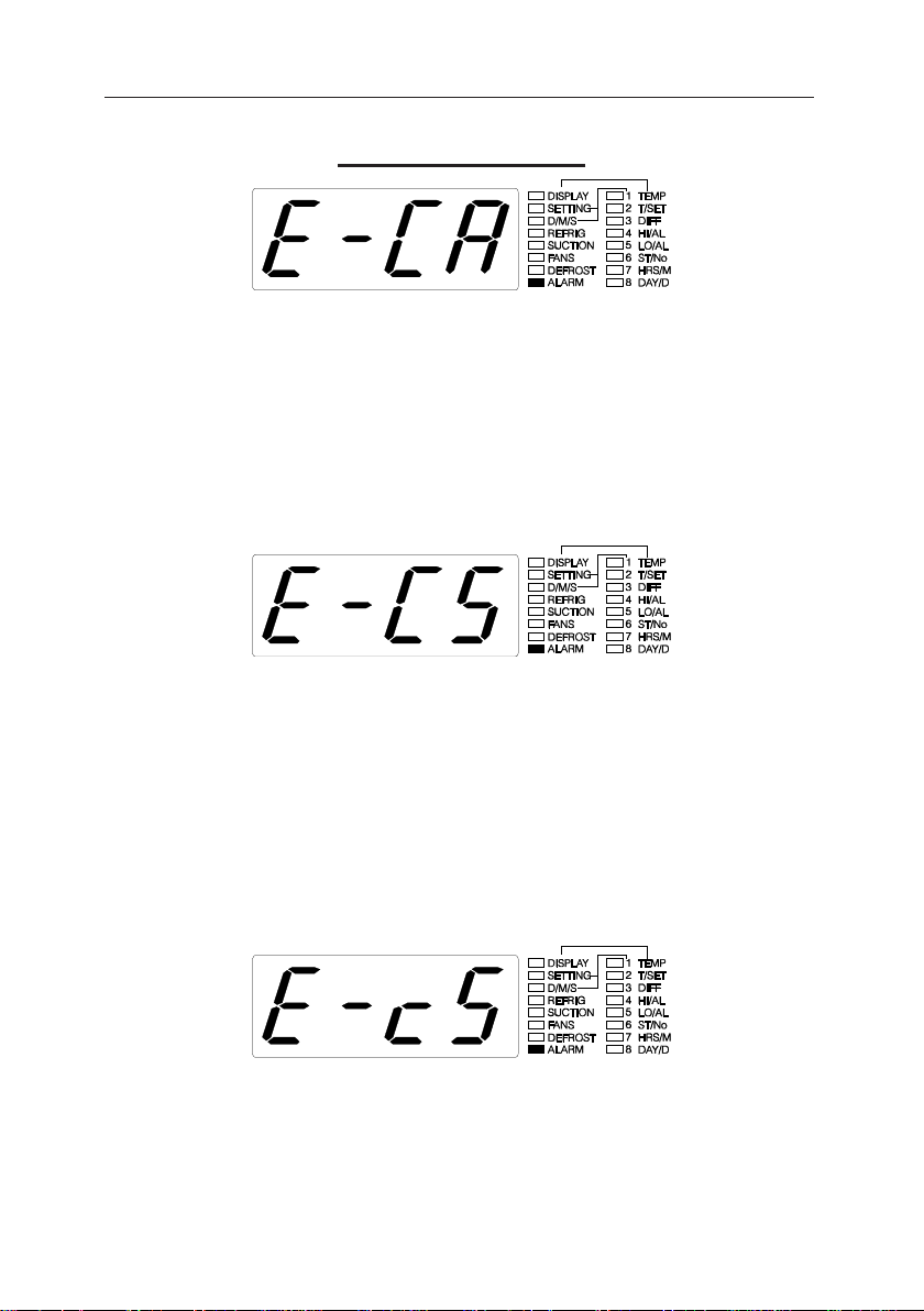
If this is displayed it means that the calibration values are corrupt or have been
altered. The alarm will be active (on) and all controls will be turned off.
To correct the alarm fault use the previous functions "CALIBRATE VALUES
CHECK & ALTER" first to check that all values for all channels are correct (if a
copy of the values was kept, use them.). After this has been done use the "CALIBRATE VALUES UPDATE" function to enter all values for the check sum and
corruption testing.
If this is displayed it means that the check sum check on all set points while the unit
was running (and was not reset by the watch dog, independent timer for the micro-
processor run time check ) is corrupt. The alarm will sound and all controls will be
turned off.
To rectify this alarm condition CHECK ALL set points to make sure that they are
valid and correct. The alarm indication will cease when the first set point is checked
but all set points must be checked as the first set point checked may not be the one
that was corrupt.
If this is displayed it means that the check sum check on all set points while the unit
was running (and was reset by the watch dog, independent timer for the microproc-
essor run time check ) is corrupt. The alarm will sound and all controls will be
turned off.
To rectify this do as the above routine (check all set point parameters).
51
Page 52
TWITE INSTRUMENTS THERMOSTAT MODEL TD-196 OPERATING MANUAL
ERROR MESSAGES CONT.
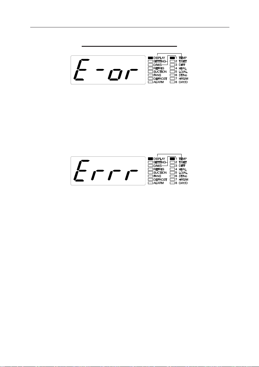
If this is displayed it means that the current sensors temperature that is displayed is
faulty. Check the cable to the sensor for an open circuit or short circuit.
If the sensor that is faulty (only if the 8 channel multiplexer option is present) is used
as the control sensor only, the alarm will sound and all controls will be turned off. If
it is used as one of the sensors in an average of temperatures the controls will be
turned off but the alarm will not sound.
If this is displayed it means that the display (only with the 8 channel multiplexer
option) is not currently available.
Press the same key combination ("ENT" and "UP" keys) until a valid display
appears.
52
Page 53
TWITE INSTRUMENTS THERMOSTAT MODEL TD-196 OPERATING MANUAL
REMOTE DISPLAY MODULE
RS485 INPUT
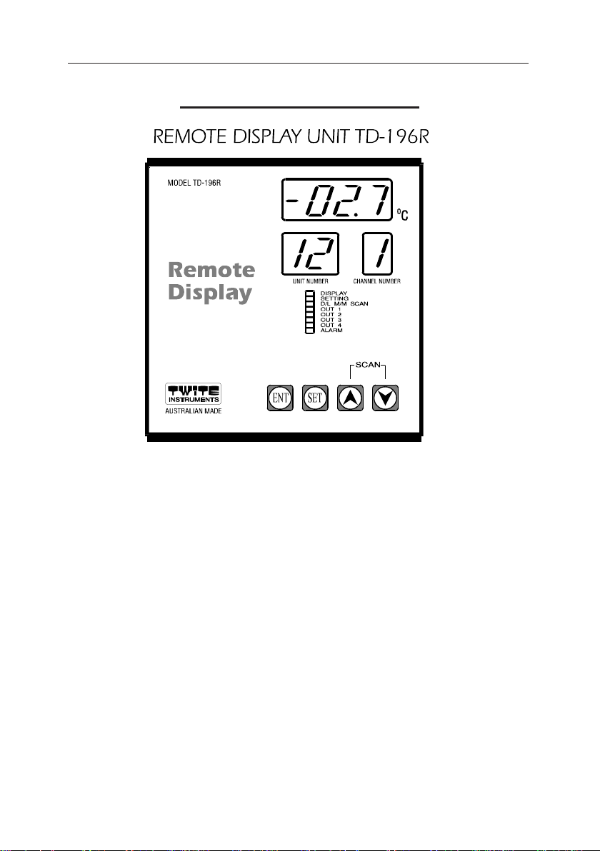
PHONO SOCKET
D25 PIN
SERIAL
SOCKET
RESET
POWER SOCKET
MOUNTING.
The unit may be fixed or placed in any convenient location and may be up to 500
metres from the furthermost TD-196 unit.
POWER SUPPLY.
The unit requires 8 to 12 volts a.c. or d.c. at 300 ma. A common 240 ac adapter
which supplies a low voltage output within this range should be used.
The polarity of the low voltage input to the TD-196R is irrelevant and may be
placed either way even if the voltage is DC.
If the unit is to be permanently mounted onto a wall, it is possible to connect the
power supply and the RS485 input from the rear of the unit, see Internal
Connections for this application.
53
Page 54

TWITE INSTRUMENTS THERMOSTAT MODEL TD-196 OPERATING MANUAL
REMOTE DISPLAY MODULE CONT.
RS485 INPUT.
The RS485 input is of the stereo phono type socket.
The + wire from all TD-196 units must be connected to the centre ring or the plug
and the - wire from all TD-196 units must be connected to the tip of the plug, the
large section (earth or section with the cover screw) is left unconnected.
If the unit is to be permanently mounted onto a wall, it is possible to connect the
power supply and the RS485 input from the rear of the unit, see Internal
Connections for this application.
PRINTER OUTPUT.
The printer output is a standard serial 25 pin D connector type and may be
connected to any EPSOM compatible (LX300 recommended) printer's serial input
port. The output plug is a 25 pin D male connector as found on most IBM or
compatible computer's serial output port. A standard serial printer cable is used for
connection to a printer.
The printer must be set for 8 data bits, no parity, 1 stop bit and 1200 baud
rate.
All print functions are set and initiated from the TD-196 thermostat units.
DISPLAY.
The display will show the UNIT No. (2 digits), CHANNEL No. (1 digit), TEMPERATURE (of the currently shown unit & channel No.) (4 digits) and the
STATUS of the currently shown unit number including an audible alarm if the
alarm is active.
54
Page 55
TWITE INSTRUMENTS THERMOSTAT MODEL TD-196 OPERATING MANUAL
REMOTE DISPLAY MODULE CONT.
KEYBOARD.
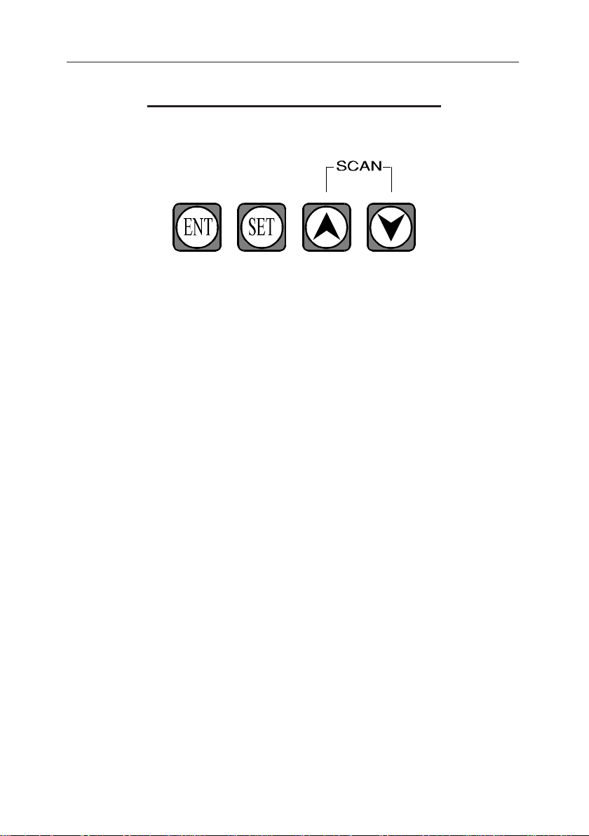
ENT KEY.
The "ENT" key is for entering the value/s selected while setting functions..
SET KEY.
The "SET" key is used to set one of the 6 functions and to select channels while
doing function 4.
"UP" (SCAN) KEY.
The "UP" (arrow and scan) key is used to select the next temperature (unit/channel)
to display while not setting functions. If setting functions, this key is used to
increase the value of the function and to increase the unit number in function 3 and
4..
"DOWN" (SCAN) KEY.
The "DOWN" (arrow and scan) key is used to select the previous temperature (unit/
channel) to display while not setting functions. If setting functions, this key is used
to decrease the value of the function and to select "YES" or "NO" in functions 2,3
and 4..
55
Page 56

TWITE INSTRUMENTS THERMOSTAT MODEL TD-196 OPERATING MANUAL
REMOTE DISPLAY MODULE CONT.
FUNCTION NUMBERS.
1 = Scan Time (the time between each channels/unit display in scan
mode)
2 = Scan Yes or No (whether the unit is to scan automatically or not).
3 = Select TD-196 Units (which TD-196 units are allowed to display).
4 = Select TD-196 Channels (which TD-196 units channels are
allowed
to display).
5 = Display Intensity (varies the brightness of the display).
6 = Baud Rate (sets the baud rate, stop bits = 1 and no parity).
SETTING FUNCTIONS.
1. SCAN TIME
Sets the time between channel scan from 1 to 50.
i.e.. 50 = 10 sec, 25 = 5, 1 = 1/4 sec approx.
PRESS “SET”
PRESS s t TO SELECT NUMBER 1
PRESS “ENT”
s t TO SELECT REQUIRED SCAN TIME FROM 1 - 50 INC. ON LED
PRESS “ENT”
SELECTION COMPLETE
2. SCAN YES OR NO
Sets whether the unit will scan or not (scans all required temperatures of units/
channels including status and alarms).
PRESS “SET”
PRESS s t TO SELECT NUMBER 2
PRESS “ENT”
s t TO SELECT "YES" OR "no" ON LED
PRESS “ENT”
SELECTION COMPLETE
56
Page 57

TWITE INSTRUMENTS THERMOSTAT MODEL TD-196 OPERATING MANUAL
REMOTE DISPLAY MODULE CONT.
SETTING FUNCTIONS CONT.
3. SCAN UNITS YES OR NO
Sets whether the remote display will scan or not for each TD-196 unit that is
connected via the RS485 serial line.
NOTE :- If the remote display is set to scan/display a TD-196 unit that is
not connected to the serial line, it will time out after approximately 1 minute and
not display/scan that unit but will not alter the set point. This means that if a TD196 unit is then connected to the serial line the remote display will automatically
pick up the information and proceed to display/scan this TD-196 unit. If a TD-196
unit is connected to the serial line and the remote display is set to not display/scan
this unit, it will not.
PRESS “SET”
PRESS s t TO SELECT NUMBER 3
PRESS “ENT”
s TO SELECT UNIT NUMBER (1 TO 16).
t TO SELECT "YES" OR "no" ON LED FOR THE UNIT NUMBER.
PRESS “ENT”
SELECTION COMPLETE
57
Page 58

TWITE INSTRUMENTS THERMOSTAT MODEL TD-196 OPERATING MANUAL
REMOTE DISPLAY MODULE CONT.
SETTING FUNCTIONS CONT.
4. SCAN CHANNELS YES OR NO
Sets whether the remote display will scan or not for each TD-196 channel for each
unit that is connected via the RS485 serial line.
NOTE :- If the remote display is set to scan/display a TD-196 units channel
that is not connected to the serial line, it will time out after approximately 1 minute
and not display/scan that units channel but will not alter the set point. This means
that if a TD-196 unit is then connected to the serial line the remote display will
automatically pick up the information and proceed to display/scan this TD-196 unit
channels. If a TD-196 unit is connected to the serial line and the remote display is
set to not display/scan this unit channels, it will not.
PRESS “SET”
PRESS s t TO SELECT NUMBER 4
PRESS “ENT”
s TO SELECT UNIT NUMBER (1 TO 16).
"SET" TO SELECT CHANNEL NUMBER (1 TO 8).
t TO SELECT "YES" OR "no" ON LED FOR THE CHANNEL
NUMBER OF THE
DISPLAYED UNIT.
PRESS “ENT”
SELECTION COMPLETE
5. DISPLAY INTENSITY.
Sets the brightness of the display from 0 - 15 inclusive.
PRESS “SET”
PRESS s t TO SELECT NUMBER 5
PRESS “ENT”
s t TO SELECT REQUIRED BRIGHTNESS ON LED (8 recommended).
PRESS “ENT”
SELECTION COMPLETE.
58
Page 59
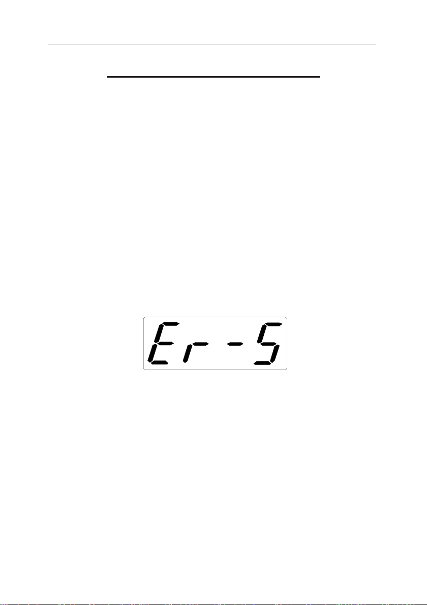
TWITE INSTRUMENTS THERMOSTAT MODEL TD-196 OPERATING MANUAL
REMOTE DISPLAY MODULE CONT.
SETTING FUNCTIONS CONT.
6. BAUD RATE SETTING.
Sets the BAUD rate for the RS485 communications between 110, 300, 1200, 2400,
4800 and 9600. The STOP bit is set at 1 STOP BIT and the PARITY is set at
NONE. The stop bit and parity cannot be changed. The TD-196 units connected to
the Remote Display (TD-196R) must be set to the same parameters.
PRESS “SET”
PRESS s t TO SELECT NUMBER 6
PRESS “ENT”
s t TO SELECT REQUIRED BAUD RATE ON LED
PRESS “ENT”
SELECTION COMPLETE.
ERROR MESSAGE.
If this is displayed on the 4 digit display, the remote display has lost the serial
communications line.
The TD-196 thermostats send their data every 30 seconds, so it may take up to 30
seconds for the Remote Display to respond to the TD-196 units after loss of communications.
Check that the line is securely connected and with the correct polarity.
Check that all TD-196 thermostats are set to the same BAUD RATE as the Remote
display. The default value is 9600.
Decrease the baud rate value to 1200 on all units.
59
Page 60

TWITE INSTRUMENTS THERMOSTAT MODEL TD-196 OPERATING MANUAL
REMOTE DISPLAY MODULE CONT.
DEFAULT VALUES.
The Remote Display may be set to its default values in one of two ways.
1: By pressing the "ENT" , "UP" and "DOWN" keys and holding them
pressed while pressing and releasing the reset switch or removing then returning
the power supply. This will put the unit into a test program. The Display will show
"r" and then "r O" to indicate that the ram is OK. then after a short time the
display will show "d P" to indicate that the default values have been entered, then
after a short time all LED digits and segments will be lit to test if all LED'S are
functioning properly.
When all LED'S are lit press the "ENT" key to reset the unit for normal running.
It may take up to 30 seconds for the Remote display to respond to the TD-196 units
data for display.
2: If the battery backed ram loses its power. The Remote Display will automatically set all values to there default values if the ram loses its power.
This is possible if the power has been disconnected from the Remote Display for 12
hours approx.
The DEFAULT VALUES are as follows :-
1 = SCAN RATE = 10
2 = SCAN YES/NO = YES
3 = UNITS TO SCAN = YES TO ALL UNITS 1-16
4 = CHANNELS TO SCAN = YES TO ALL CHANNELS ALL UNITS
5 = DISPLAY INTENSITY = 8
6 = BAUD RATE = 9600
NOTE :-
When all values are set to their default values and all TD-196 units
have a baud rate of 9600 the remote display will automatically detect the
correct units and channels to display/scan providing the serial line is connected
correctly.
60
Page 61
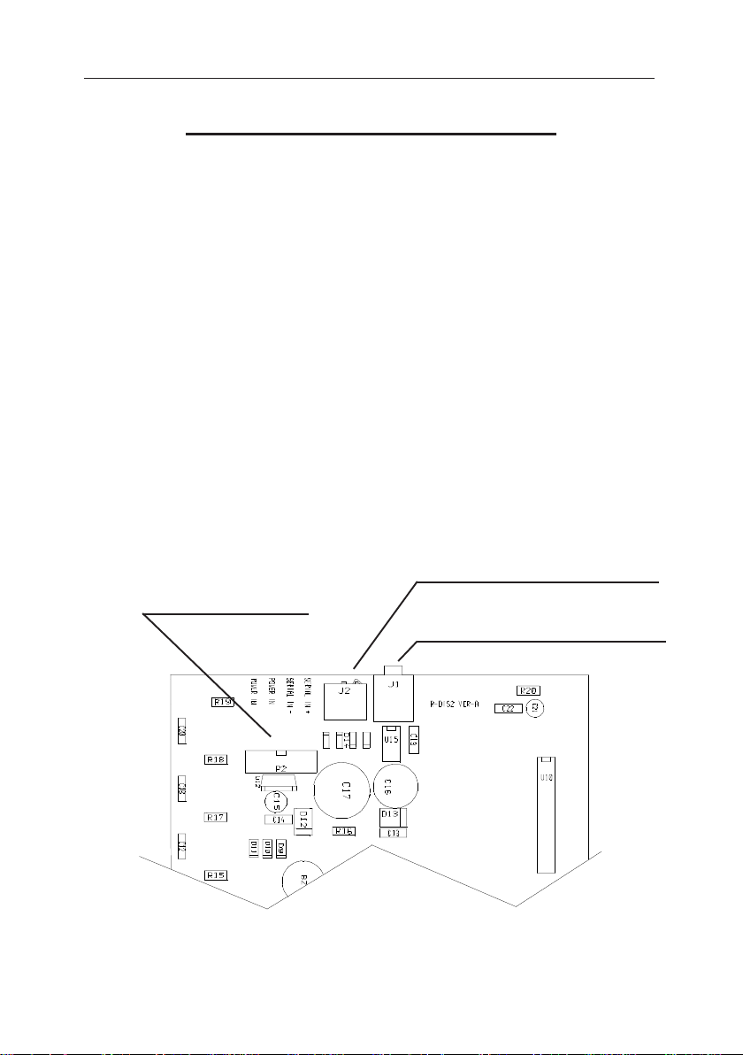
TWITE INSTRUMENTS THERMOSTAT MODEL TD-196 OPERATING MANUAL
REMOTE DISPLAY MODULE CONT.
RESET.
To reset the Remote Display, press the reset button (lightly with a small tipped pen
or pencil) and release it, or disconnect the power supply and re connect. This will
reset the unit in case of malfunction.
INTERNAL CONNECTIONS (POWER & SERIAL).
The power and serial lines may be connected internally if required.
First remove the right hand side panel and slide the front panel (with circuit board)
out. Turn over to expose the underside of the circuit board. The screw connections
are placed next to the power input socket. Connect the correct wire to its labelled
screw connector. A hole will be necessary to allow the entry of the cable (in the
side panel or the bottom of the unit. When the handling the circuit board be sure to
not touch the components or circuit tracks as static electricity will destroy the
components.
SERIAL & POWER
CONNECTORS
SERIAL INPUT SOCKET
POWER INPUT SOCKET
61
Page 62

TWITE INSTRUMENTS THERMOSTAT MODEL TD-196 OPERATING MANUAL
CALIBRATION VALUES
CHANNEL NUMBER HIGH LOW
1
2
3
4
5
6
7
62
8
Page 63

TWITE INSTRUMENTS THERMOSTAT MODEL TD-196 OPERATING MANUAL
NOTES
63
Page 64

TWITE INSTRUMENTS THERMOSTAT MODEL TD-196 OPERATING MANUAL
NOTES
64
 Loading...