

Twister R/C, 2.4Ghz Computer Radio Operation Manual
2.4GHZ COMPUTER RADIO
OPERATION MANUAL
V11.10

2
Warranty conditions
J. Perkins Distribution Ltd. guarantee this product to be free of manufacturing and assembly defects for a period of one
year from time of purchase and Model Engines Pty Ltd. for 30 days. This does not affect your statutory rights. This warranty
is not valid for any damage or subsequent damage arising as a result of a crash, misuse, modification or for damage or
consequential damage arising as a result of failure to observe the procedures outlined in this manual. Operation of this
model is carried out entirely at the risk of the operator. Please note that, whilst every effort is made to ensure the accuracy
of instructions and material included with this product, mistakes can occur and neither J. Perkins Distribution Ltd/Model
Engines (Aust.) Pty. Ltd. nor it’s distributors will be held liable for any loss or damage arising from the use of this model or
for any loss or damage arising from omissions or inaccuracies in the associated instructions or materials included with this
product.
We reserve the right to modify the design of this product, contents and manuals without prior notification.
© 2010 J Perkins Distribution Ltd, Lenham, Kent, UK ME17 2DL.
www.jperkinsdistribution.co.uk
Model Engines (Aust.) Pty. Ltd., Noble Park, Victoria 3174, Australia. www.modelengines.com.au. All rights reserved. E&OE.
EU rEgUlations
J Perkins Distribution Ltd declares that this remote control system is in compliance with the essential requirements and
other relevant provisions of Directive 1999/5/EC on Radio equipment and Telecommunications Terminal Equipment. A copy
of the declaration(s) of conformity can be obtained from J Perkins Distribution Ltd, Ashford rd, Lenham, Kent. UK ME17 2DL.
This system complies with the EU directive on Waste Electrical and Electronic Equipment. Do not dispose of this product
in household waste. At the end of the products’ life, dispose of it at a designated collection point for the recycling of waste
electrical and electronic equipment.
Please contact your supplier for any advice required on disposal.
contEnts
TRANSMITTER LAYOUT ............................. 4
CONTROL LAYOUT (MODE 1) .................................................4
CONTROL LAYOUT (MODE 2) .................................................5
CONTROL LAYOUT (MODE 1) ..................... 6
MODEL MEMORY ...................................... 7
PROGRAMMING IN HELI MODE ................. 8
SERVO REVERSING .................................................................8
DUAL RATE ................................................................................8
SUB TRIM ..................................................................................9
TRAVEL ADJUST ......................................................................9
SW– TYP ...................................................................................9
THR-CUR (NORMAL) .............................................................10
THR-CUR (IDLE UP) (NORMAL) ...........................................10
PIT-CUR (NORMAL) ............................................................... 10
PIT-CUR (IDLE UP) .................................................................11
PIT-CUR (THROTTLE HOLD) .................................................. 11
HLD-ON/OFF ............................................................................11
EXIT PROGRAMMING MODE ..............................................11
PROGRAMMING IN AERO MODE .............. 12
SERVO REVERSING ...............................................................12
DUAL RATE ..............................................................................12
SUB TRIM ................................................................................13
TRAVEL ADJUST ....................................................................13
AIL-FLP ....................................................................................13
AIL-ELE ....................................................................................14
ELE-RUD ..................................................................................14
ELE-AIL ....................................................................................14
RUD-ELE ..................................................................................14
THR-CUR (NORMAL) .............................................................15
EXIT PROGRAMMING MODE ..............................................15

3
introdUction
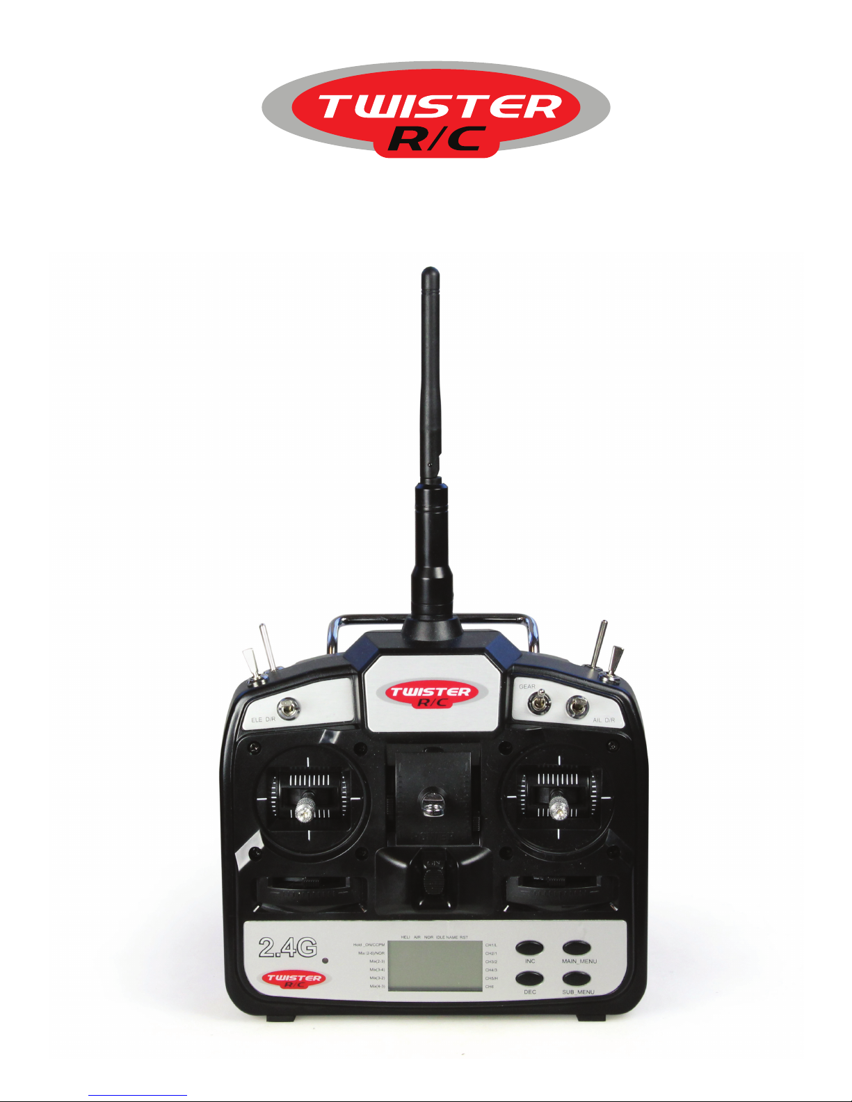
Thank you for purchasing Twister 2.4GHz computer
radio control system. It is designed for remotely
operating R/C model aircraft safely in the easiest
possible manner without the need for crystals.
It’s uncomplicated yet sophisticated design makes
it an ideal first system or a general purpose sport
system for R/C modelling.
It uses state-of-the-art computer technology
to bind it’s transmitter and receiver in such a
fashion that, under most model flying conditions,
interference that would normally cause loss of
control in 35MHz or 27MHz equipment is nearly
always rejected—and in most cases radio
functionality is entirely unaffected. This makes for
a safer, more reassuring flying experience.
It also enables a pilot to turn up, switch on and
fly under most conditions—subject to local flying
guidelines and rules.
safEty information
WARNING!
This equipment must be assembled carefully
into an appropriate R/C aircraft according to the
manufacturers’ recommendations.
Note that Twister 2.4GHz computer radio is not
a ‘full range’ system and must only be used with
small Park Flyer/ helicopter R/C models operated
at relatively short range (around 150 metres).
This product is a sophisticated control system for
model aircraft and is not a toy. Suitable only for
persons aged 14+
Check all radio equipment carefully before use
and range check before every flight.
Never fly near people, animals, buildings, power
lines, water or trees.
Ensure that all batteries are either fresh (if
alkaline) or charged (if rechargeable) before
using this equipment.
In the UK we recommend you observe BMFA
safety codes at all times when operating radio
controlled models.
This equipment is designed to be installed
and used only within a radio control hobby
environment.
2.4GHz signals are less tolerant of obstacles so
never fly close to structures, trees, hedges which
if flown behind may cause a temporary loss of
signal.
Never fly in rain.
UK air laW, Bmfa & safEty
All model aircraft operated in the UK are subject
to UK Air Law. It should be noted that in the UK
a considerable burden of responsibility and a
strict duty of care lie with the pilot of any model
aircraft. Under UK Air Law the pilot assumes all
responsibility for his aircraft.
Radio control model aircraft are potentially
capable of inflicting severe personal injury or
even death to people or animals and can cause
considerable damage to property if operated
incorrectly or irresponsibly.
In the UK, the British Model Flying Association
(BMFA) (http://www.bmfa.org) is responsible for
overseeing all aspects of model flying.
If you are new to R/C modelling we strongly
recommend you download the BMFA handbook
(http://www.bmfa.org/handbook/index.html) which
contains much useful information about model
flying including legal, insurance, safety obligations
and technical recommendations for model pilots.
not What yoU ExpEctEd?
If the information presented in the preceding
paragraphs and opposite is not what you expected
and you either cannot or choose not to accept
the responsibilities associated with operating this
equipment in a model in the UK, you should not buy
this product.
In the event you have already purchased this
product; you should return the product in it’s
original condition and obtain a refund from your
supplier.

4
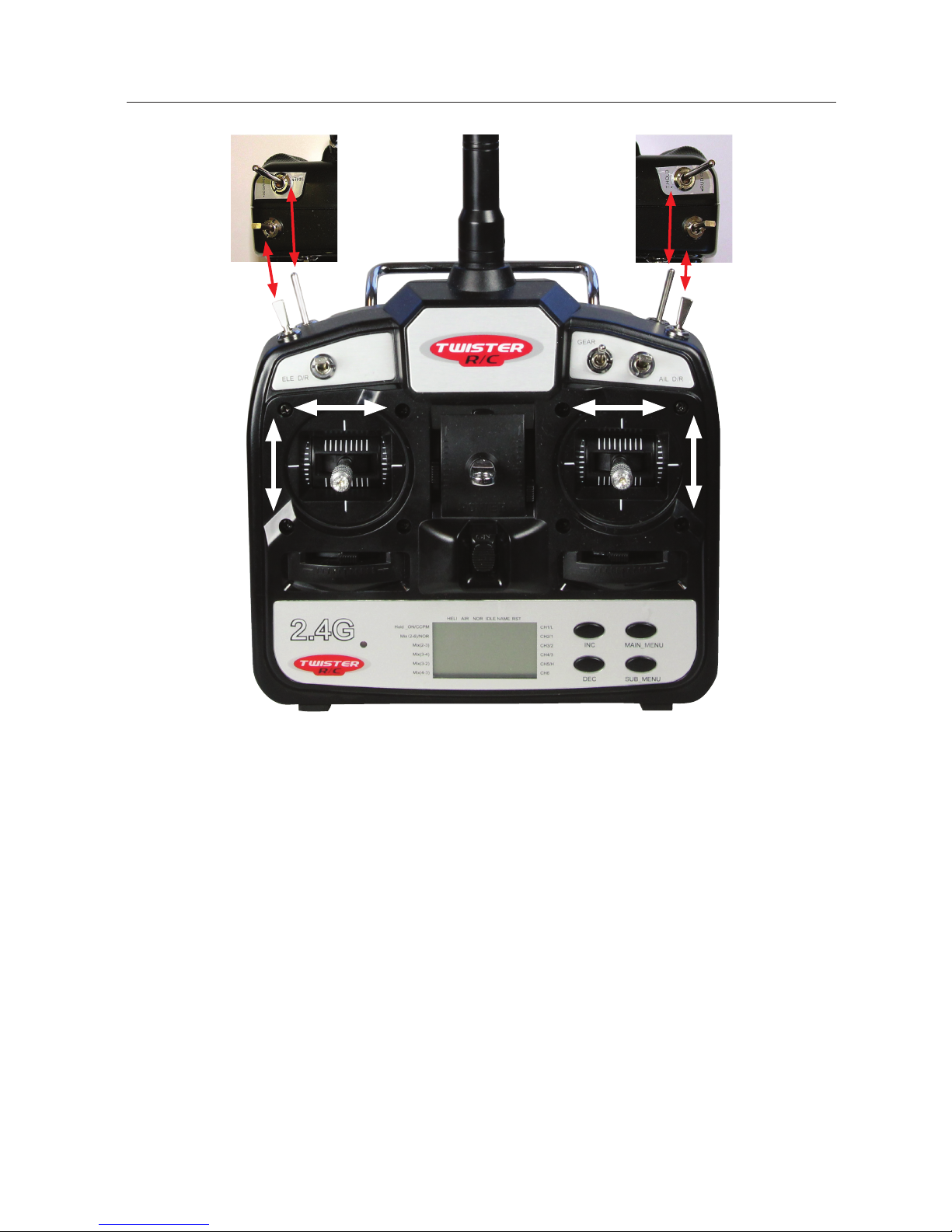
transmittEr layoUt
CONTROL LAYOUT (MODE 1)
1
2 10
11
12 16
13
14
15
3
4
5
6
17 19
18 20
7
8
9
1. Elevator Control
2. Rudder Control
3. Elevator Dual Rate Switch
4. Rudder Dual Rate Switch
5. Throttle Hold Switch
6. Trainer Switch
7. 3D/Aerobatic Switch (Idle Up)
8. Gyro Mode Selector Switch (Heli)/Retractable Landing Gear Switch (Aircraft)
9. Aileron Dual Rate Switch
10. Aileron Control
11. Throttle Control
12. Rudder Trim Lever
13. Elevator Trim Lever
14. Throttle Trim Lever
15. On/Off Power Switch
16. Aileron Trim Lever
17. INC Button for increasing values during programming
18. DEC Button for decreasing values during programming
19. MAIN_Menu Button for changing Main Menu Categories during programming
20. SUB_Menu Button for scrolling within Main Menu categories during programming
5
CONTROL LAYOUT (MODE 2)
1
2 10
11
12 16
13
14
15
3
4
5
6
17 19
18 20
7
8
9
1. Throttle Control
2. Rudder Control
3. Elevator Dual Rate Switch
4. 3D/Aerobatic Switch (Idle Up)
5. Trainer Switch
6. Throttle Hold Switch
7. Rudder Dual Rate Switch
8. Gyro Mode Selector Switch (Heli)/Retractable Landing Gear Switch (Aircraft)
9. Aileron Dual Rate Switch
10. Aileron Control
11. Elevator Control
12. Rudder Trim Lever
13. Throttle Trim Lever
14. Elevator Trim Lever
15. On/Off Power Switch
16. Aileron Trim Lever
17. INC Button for increasing values during programming
18. DEC Button for decreasing values during programming
19. MAIN_Menu Button for changing Main Menu Categories during programming
20. SUB_Menu Button for scrolling within Main Menu Categories during programming
6
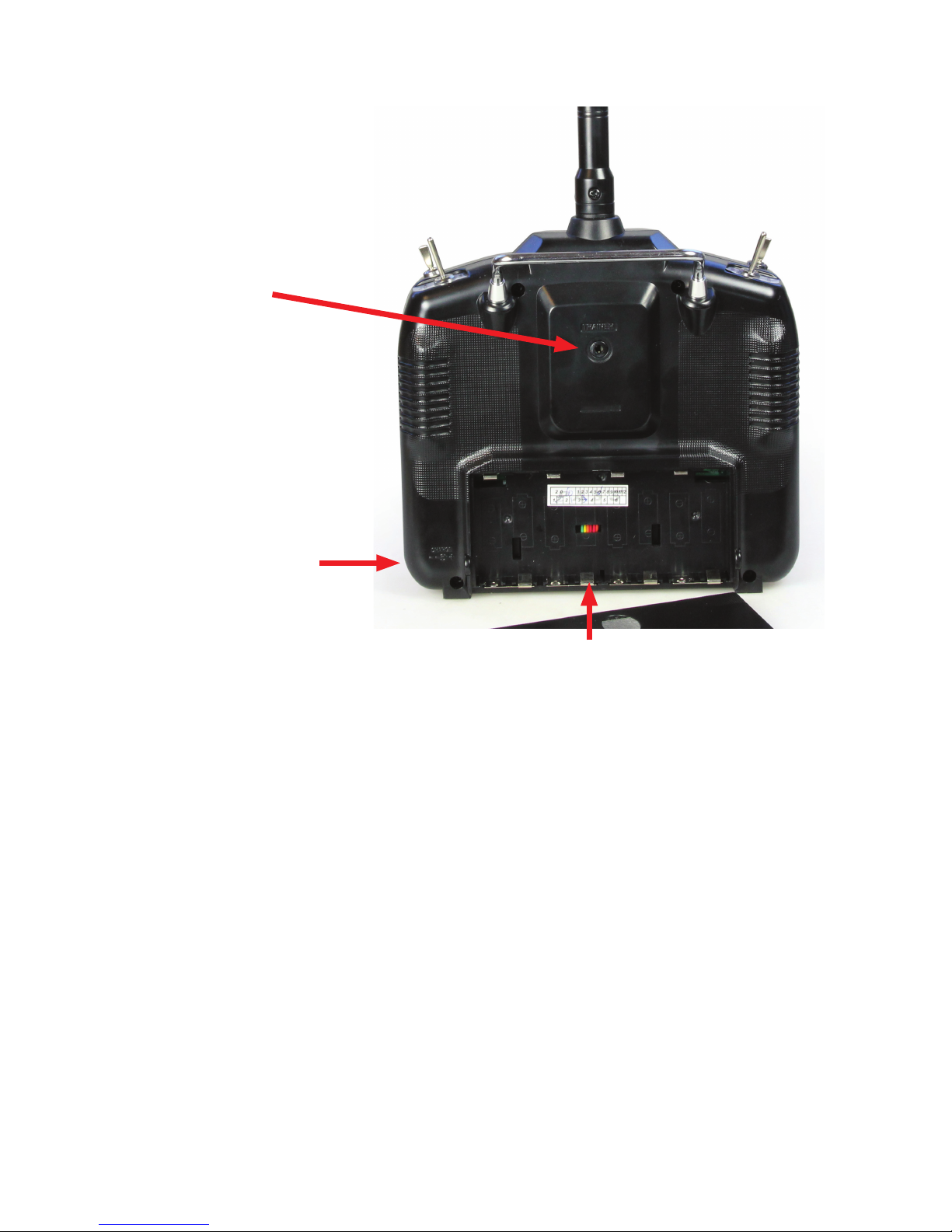
control layoUt (modE 1)
Trainer Cord Socket
Charging Jack for charging
rechargeable Ni-Mh batteries
IMPORTANT:
THE CENTRE PIN OF THE CHARGING
JACK IS NEGATIVE!
Use of the incorrect charger could
severely damage the radio and
batteries.
Battery compartment for 8 x AA size batteries.
Re-chargeable Ni-Mh can be used.
 Loading...