

Page 1

Rev: 2014.11.04.v002a
1
MOTOR: 1x 18-20g/1750-1800kv Outrunner
ESC: 1x 10-12 amp
SERVOS: 2x 4-5g / 1x 8-9g
PROP: 1x 8x4.3
BATTERY: 2s 360mAh LiPo
USA Distributor
Twisted Hobbys
www.twistedhobbys.com
RADIO: min. 4 channel
WINGSPAN: 32 inches
LENGTH: 31 inches
AUW: 160 to 190 grams
llll
llll
iiii
iiii
tttt
tttt
eeee
eeee
SSSS
SSSS
eeee
eeee
rrrr
rrrr
iiii
iiii
eeee
eeee
ssss
ssss
YYYY
YYYY
aaaa
aaaa
kkkk
kkkk
aaaa
aaaa
nnnn
nnnn
dddd
dddd
LLLL
LLLL
aaaa
aaaa
ssss
ssss
eeee
eeee
rrrr
rrrr
Page 2

Rev: 2014.11.04.v002a
2
TABLE OF CONTENTS
TABLE OF CONTENTSTABLE OF CONTENTS
TABLE OF CONTENTS
Page
WARNING INFORMATION ....................................................................................................................................................... 3
SHIPPING DAMAGE.................................................................................................................................................................... 3
OUR MISSION............................................................................................................................................................................... 3
SAFETY NOTES............................................................................................................................................................................ 4
IMPORTANT: PRIOR TO ANY ASSEMBLY................................................................................................................... 4
KIT CONTENTS............................................................................................................................................................................ 5
TOOLS & ADHESIVES NEEDED .............................................................................................................................................. 6
THE BUILD.................................................................................................................................................................................... 7
CENTER OF GRAVITY ............................................................................................................................................................. 28
CONTROL THROWS................................................................................................................................................................. 28
PRE-FLIGHT & TESTING ........................................................................................................................................................ 29
P
REFLIGHT CHECKS
29
Motor 29
Flight Controls 29
Batteries 29
Radio 29
Range Check 29
F
LIGHT TESTING
29
S
TORAGE
29
OPTIONAL PARTS..................................................................................................................................................................... 30
NOTES & S/U SHEET................................................................................................................................................................. 31
TIPS AND TRICKS ..................................................................................................................................................................... 32
Page 3
Rev: 2014.11.04.v002a
3
TWISTED HOBBYS
Website: www.twistedhobbys.com – email: sales@twistedhobbys.com
Thank you for your purchasing a Twisted Hobbys’ model. Please read through the entire manual before beginning to
build this model. If you have any questions please contact us at the above indicated email address.
WARNING INFORMATION
WARNING INFORMATIONWARNING INFORMATION
WARNING INFORMATION
This R/C Aircraft is not a toy! Read and understand the entire manual before assembly. If misused, it can cause serious bodily harm and
property damage. Fly only in open areas, and AMA (Academy of Model Aeronautics) approved flying sites. Do not over look the warnings
and instructions enclosed or those provided by other manufactures’ products. If you are not an experienced pilot and airplane modeler you
must use the help of an experienced pilot or an authorized flight instructor for the building and flying of this model aircraft.
These instructions are suggestions only on how to assemble this model. There are other ways and methods to do so. Twisted Hobbys has
no control over the final assembly, the materials and accessories used when assembling this kit, or the manner in which the assembled
model, installed radio gear and electronic parts are used and maintained. Thus, no liability is assumed or accepted for any damage
resulting from the use of the assembled model aircraft or from this instruction manual including but not limited to direct, indirect,
incidental, special, and consequential damages. By the act of using this user-assembled product, the user accepts all resulting liability. In
no event shall Twisted Hobbys’ liability exceed the original purchase price of the kit.
SHIPPING DAMAGE
SHIPPING DAMAGESHIPPING DAMAGE
SHIPPING DAMAGE
Twisted Hobbys checks each plane before shipping to ensure that each kit is in fine condition. We have no bearing on the condition of any
component parts damaged by use, modification, or assembly of the model. Inspect the components of this kit upon receipt. If you find any
parts damaged or missing, contact Twisted Hobbys immediately. We will not accept the return or replacement of parts on which assembly
work has already begun. Twisted Hobbys reserves the right to change this warranty at anytime without notice.
OUR MISSION
OUR MISSIONOUR MISSION
OUR MISSION
To provide the best products and service to our customers at the lowest prices possible. We take great pride in
our company, our commitment to customer service and in the products we sell. Our online store is designed
to provide you with a safe and secure environment to browse our product catalog.
Thank you for shopping with Twisted Hobbys!
Page 4
Rev: 2014.11.04.v002a
4
SAFETY NOTES
SAFETY NOTESSAFETY NOTES
SAFETY NOTES
Before assembling and flying this model, read carefully any instructions and warnings of other
manufacturers for all the products you installed or used on your model, especially radio
equipment and power source.
Check thoroughly before every flight that the airplanes’ components are in good shape and
functioning properly. If you find a fault do not fly the model until you have corrected the
problem.
Radio interference caused by unknown sources can occur at any time without notice. In such a
case, your model will be uncontrollable and completely unpredictable. Make sure to perform a
range check before every flight. If you detect a control problem or interference during a flight,
immediately land the model to prevent a potential accident.
Youngsters should only be allowed to assemble and fly these models under the instruction and
supervision of an experienced adult.
Do not operate this model in a confined area.
Do not stand in line with, or in front of a spinning propeller and never touch it with any object.
IMPORTANT: PRIOR TO ANY ASSEMBLY
Please Note: after removing kit from shipping box, lay each piece flat on a
hard surface, this will allow the airframe to straighten out if lightly bent
from shipping. Do not worry since EPP is very pliable and can be bent back
if out of shape.
Page 5
Rev: 2014.11.04.v002a
5
kit cont
kit contkit cont
kit contents
entsents
ents
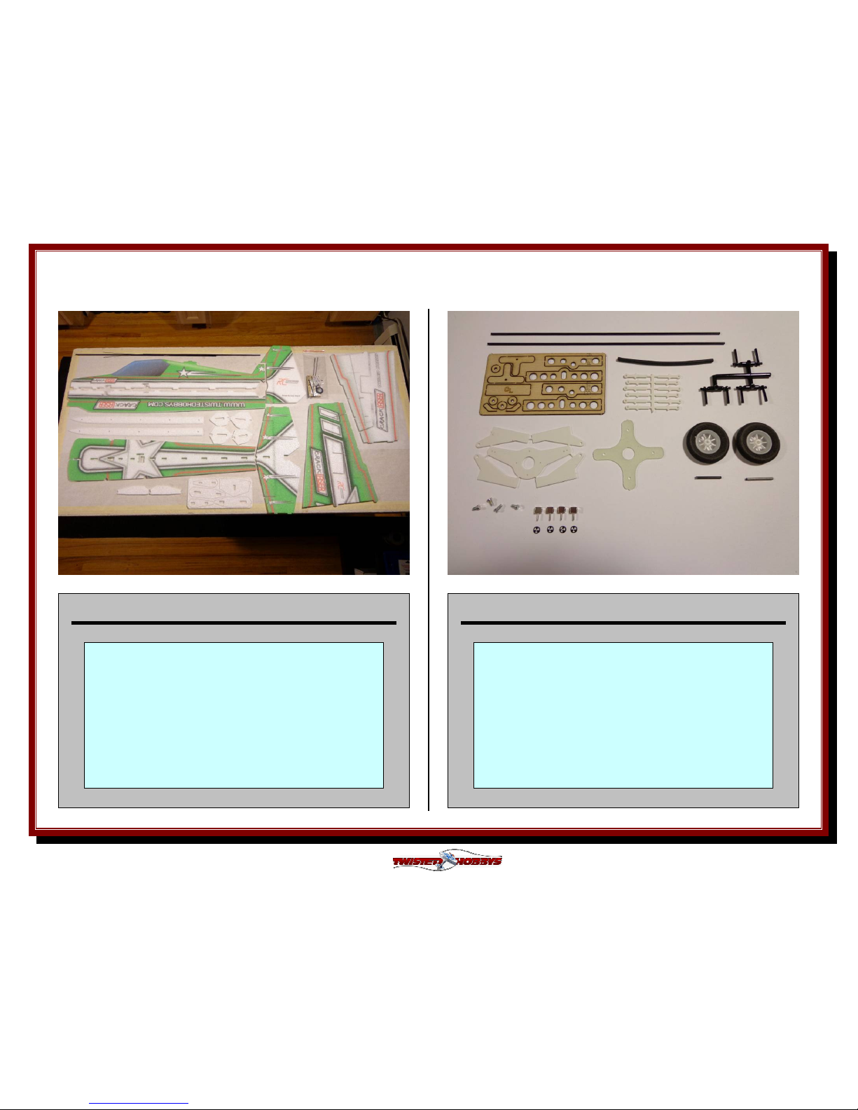
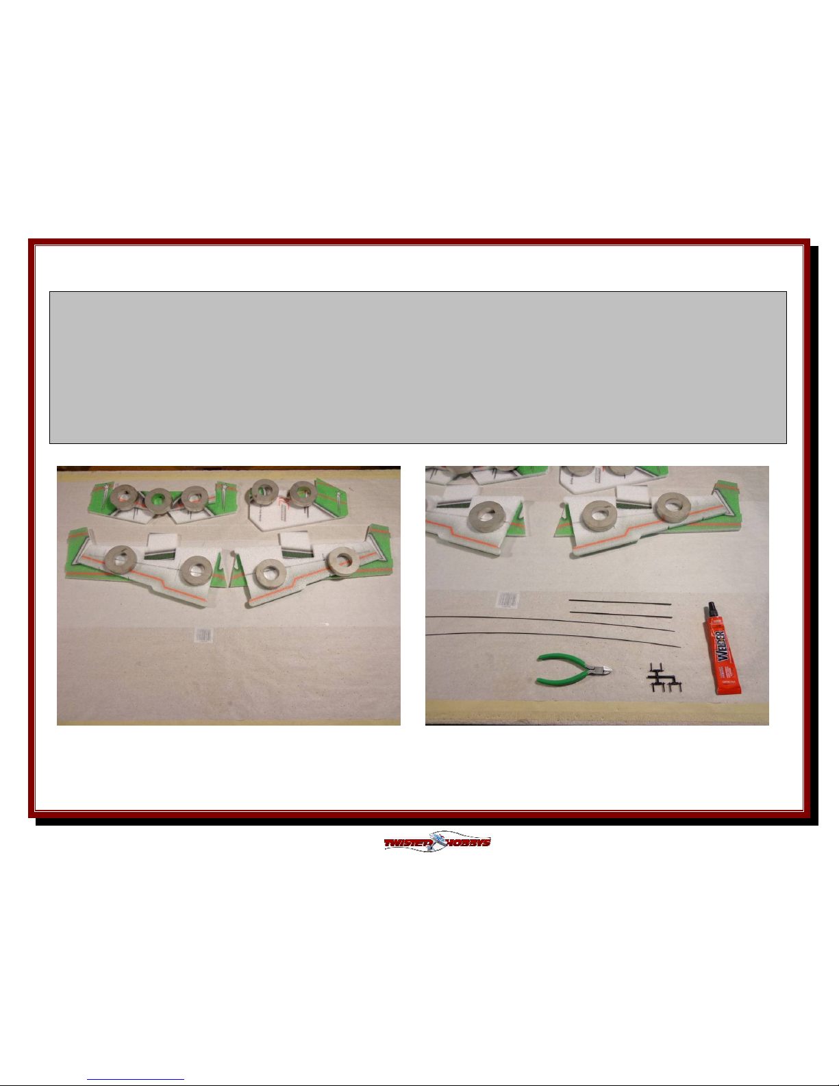
MAIN AIRFRAME COMPONENTS AND KITS
Double check that you have all the
above pictured items. The Carbon
bundle includes tail push rods and
wing spars. Also pictured above is the
bag with all the small hardware items,
see the detail to the right for items is
should contain.
HARDWARE KIT DETAIL
Double check that you have all the
above pictured items. There are two
extra snap links included and the use
of the shrink tubing is optional. If any of
the airframe or hardware items are
missing, contact Twisted Hobbys
before starting your build.
Page 6
Rev: 2014.11.04.v002a
6
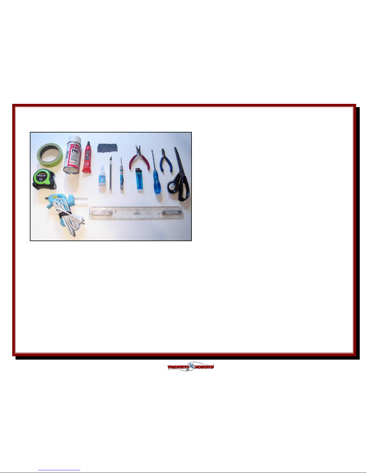
Tools
Tools Tools
Tools &&&& Adhesives Needed
Adhesives Needed Adhesives Needed
Adhesives Needed
• Lighter
• Small drill bits
• Tape Measure and Ruler
• Black Sewing Thread
• Welders Glue
• Hobby Knife w/new Blade
• Needle Nose Pliers
• Wire Cutters
• Low Temp Hot Glue Gun
• Course Sand Paper
• Scissors
• Small Phillips Screw Driver
• Thin & Medium CA
• CA Applicator Tips
• Activator
Tools shown and listed are suggestions only
. D
epending
on your building technique you may not need everything
indicated – and/or – you may find that other tools
available to yourself may be of benefit to your Build.
It is also recommended that you have a flat building
surface, one that will accept stick pins and push pins.
An Acrostic Ceiling panel from your local hardware store
fits this bill nicely, and will lay flat on your work table.
Over size / long push pins are available at your local
craft store. These two items are by no means required,
but will aid in the building process, and can be used for
future projects.
Page 7
Rev: 2014.11.04.v002a
7
THE BUILD
THE BUILDTHE BUILD
THE BUILD
CONSTRUCTION METHODS:
Building surface should be at least 2ft x 4ft and flat. Weights or some small heavy objects will be handy for holding things in place during
the time glue is setting.
Welders glue is used for FOAM TO FOAM joints. Thin and Medium CA are used on the PLASTIC TO FOAM and CARBON TO FOAM joints.
When using the Welders glue for a butt joint, apply a thin film to each surface, allow to sit for approx five minutes and then
assemble. Note that this method will create a nearly instant bond, so locate carefully when bringing the two pieces together. If alignment
is necessary or a slip joint, do not allow the glue to tack up, simple apply and join immediately, you will have several minutes to locate the
two parts before the glue sets up. In most cases the parts being glued can be handled with care in 30 minutes, full cure is approx 24
hours.
Locate the hinged items as shown above, bend them back
onto each other as s
hown and let set for an hour or so. This
process will help to loosen up the movement of the control
surface, and is necessary to prevent servo damage.
Gluing the snap links onto the ends of the controls rods is
important to do at this time... the glue will need to cure for
at least 24 hours in order to achieve it's full strength.
Locate the rods and snap links as shown above.
Page 8
Rev: 2014.11.04.v002a
8
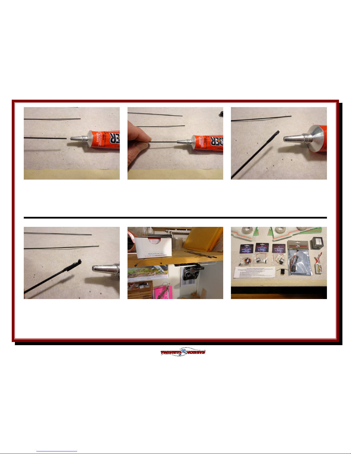
A quick link will be glued to the end o
f
the 4 control rods. Hold the rod with
your finger tips...
.... dunk it approx 1/2" into the nozzle
of the Welders tube as show and twist a
time or two.
Pull the rod out and check that you
have a nice even coat of glue as shown,
if not, repeat the process
Attach a snap link as shown. Notice
that the snap link has a "saddled" area,
this should be where you rest the
control rod
Repeat this for the other three control
rods and set a side in a safe place to
dry for a minimum of 24 hours
Locate all of the electronics you will be
using. Now is a good time to check that
everything is working properly
Page 9
Rev: 2014.11.04.v002a
9
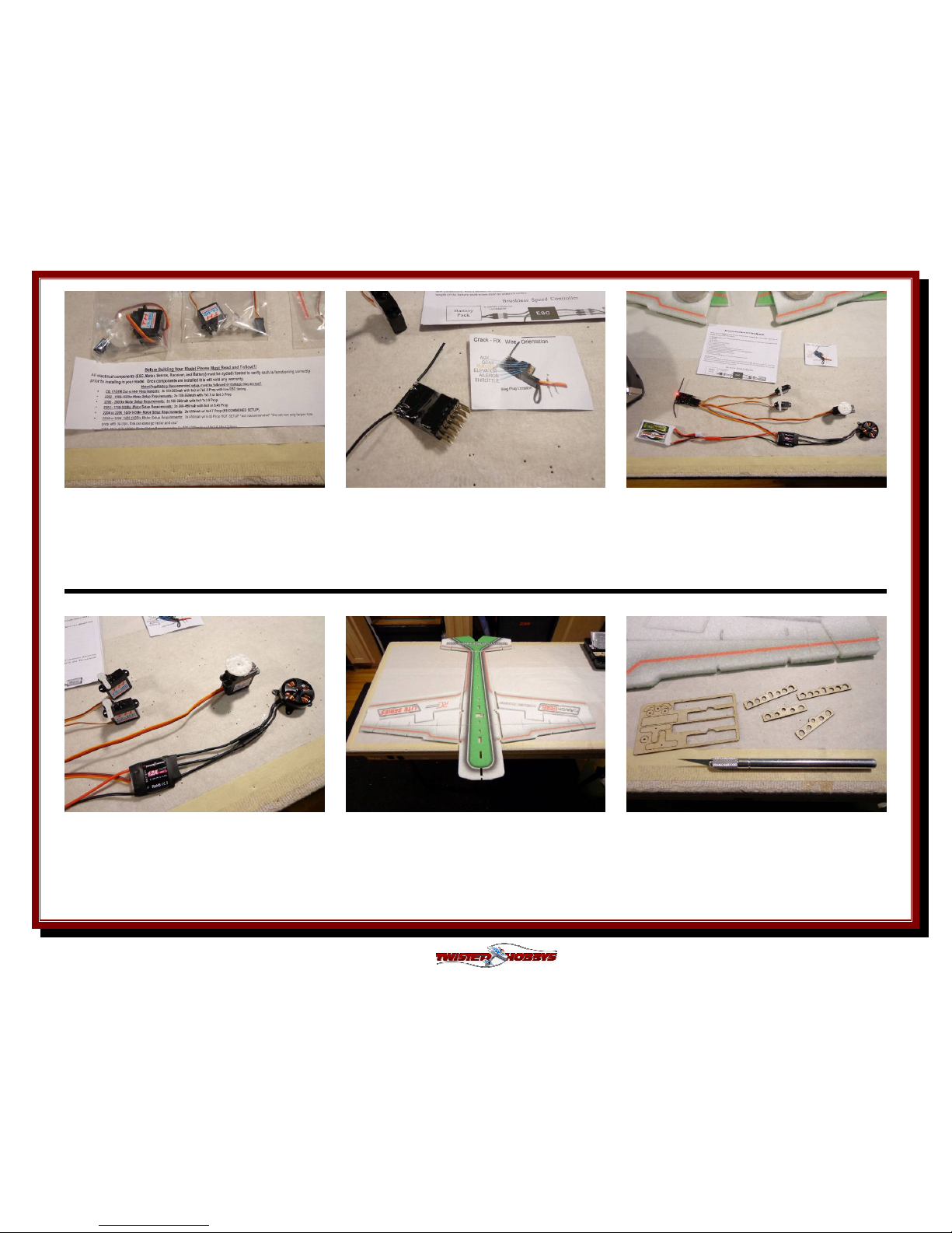
If using the Twisted Hobbys' power
combo, please read the included notice
regarding the electronics warranty
Create a program in your transmitter
for this model and bind the receiver as
required
Hook up the entire electronis system as
shown. Mount and center the control
horns and servos as shown. Test for
proper operation of all items
Now is also a good time to Calibrate
your ESC according to the included
directions
Locate the items shown above and
apply a tack coat to the mating surfaces
and let sit for approx 5 minutes before
joining together
While the glue in the previous step is
tacking up, locate the wood kit and
remove the 4 wing ribs as shown
Page 10
Rev: 2014.11.04.v002a
10
Once the glue has tacked up, bring all
the pieces together. Note that all the
tabs and slots should line up and parts
are "keyed" for proper orientation
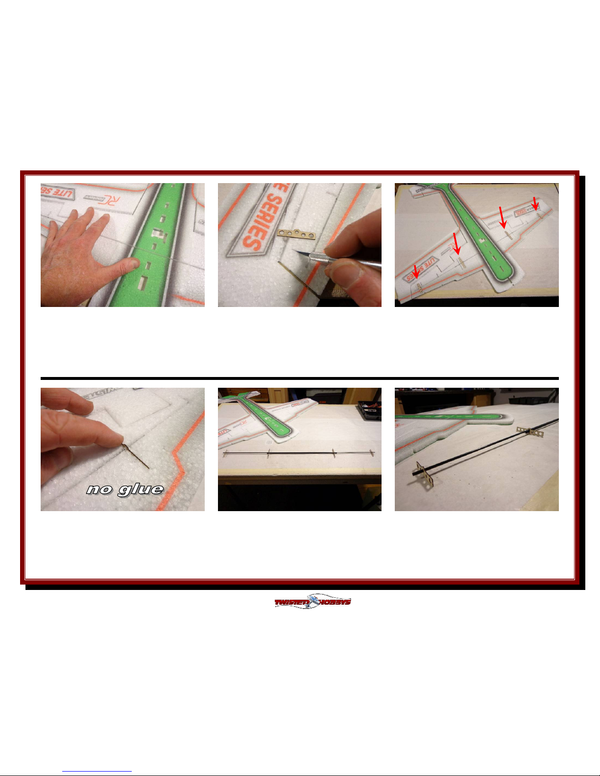
Clean out the slots in the wing where
the ribs will be installed. Note that the
ribs are the same width as the wing
thickness
Check the fit of the ribs to the slot in
the foam, with the exception of the
humped area, the rib should sit flush
with both the top and bottom surfaces
Test fit the wing spars and ribs on the
bench out side of the wing first, this
will give you an understanding of how
the pieces go together. No Glue
Close up of the left underside pieces.
No Glue
The bigger ribs are located toward the
fuselage and the small ribs towards the
wing tip. Note that we are working from
the bottom side of the aircraft
Page 11

Rev: 2014.11.04.v002a
11
Close up of how the spars stack up
inside the slot of the inner rib. No Glue
Take the whole assembly and lay it into
the slots on the bottom side of the wing
as shown... still test fitting.... No Glue
Gently lower the spar/rib assembly into
its precut area. Notice that the shorter
center spar should be centered and
entering the wing first
Make sure that the rib slots you cut
and the precut spar slots are deep
enough to allow everything to sit flush
as shown above
Once you are happy with the dry fit,
remove the spar/rib assembly and fill
all the appropriate slots in the wing
with Welders
Lower the spar/rib assy back into the
wing like was done on the dry fit. Press
down in all areas to fully seat the spars
and ribs into their respective slots
Page 12

Rev: 2014.11.04.v002a
12
With a paper towel, wipe away any
extra Welders that has squished out
Put some weight on the wing in the
area of the spar/rib assembly as shown
and allow to dry for a couple hours
While that is drying, prepare the servos
and servo arms
Install one of the adjustable links into
the outer most hole of the servo arm,
than with the cupped side facing up
press the retainer onto the pin
Repeat with the other tail servo arm,
double check that your servos are
centered and secure the arms with the
small screw include with each servo
With the servo centered, mount the
round servo horn for the aileron servo
as shown and slightly enlarge the holes
so that the mount screws will self tap
Page 13

Rev: 2014.11.04.v002a
13
Apply a thin layer of Welders to the
differencial horn as shown above
Install the Diff Horn from the
underside of the stock servo horn as
pictured, line u
p the holes between the
two pieces
Thread the screws in as shown, make
sure the holes in the stock horn were
big enough to let the screws tap in with
out splitting the horn
Trim off the extra screw length with
some side cutters and grind smooth
with a motor tool or hand file
Install the adjustable links from the
side shown, use the same technique as
with the tail servo horns
All the servos ready to install in a later
step. Make sure they are electronically
centered and that the horns are
attached as shown above
Page 14

Rev: 2014.11.04.v002a
14
Building the landing gear struts is next
gather up the pieces shown. You will
also need some CA, Kicker and thread
Drill out the center of the wheels to fit
the small axle stubs, should be approx
1/16" diameter
With a drop of medium CA join the
rectangle carbon stut with the small
wood piece as shown.
Agian with a drop of medium CA attach
the stub axle as shown and hit with
kicker
Unspool approx. 6 to 8 inches of thread
as shown above
Wrap the thread as shown and soak
with thin CA and hit with Kicker. Install
the inside washer and also CA, slide on
the wheel and outside washer
Page 15

Rev: 2014.11.04.v002a
15
CA the out washer and
hit with Kicker.
Medium CA works better here than the
thin, as it will not run along the axle
and freeze up the wheel
Install the wheel pant brace as shown.
Make sure that it is spaced out enough
to let the wheel spin freely
Align the brace as shown in the picture
above and then glue from the outside
with medium CA and Kicker
Repeat for the other strut and set aside
to be installed in a later step
Once happy with the fit up apply a thin
coat of Welders to the mat
ing surface of
the horizontal fuselage section
Install the aileron servo (no glue) as
shown and test fit the bottom section of
the fuselage, it may need to be trimmed
a little around the aileron servo.
Page 16

Rev: 2014.11.04.v002a
16
Immediately apply a thin layer to the
mating surfaces of the lower vertical
fuselage....
Bring the two pieces together. You will
have a little time to work with and
adjust for squareness
Make sure pieces are true to each
other, and fully seated to one another,
apply pressure for approx 15 min.
before moving
As with the bottom fuselage, check the
fit of the upper fuselage and make
additional cuts as needed
Apply a thin layer of Welders to the
mating surface as shown
Install the tail servos. Just set them in
place. Do Not Glue them at this time.
Page 17

Rev: 2014.11.04.v002a
17
Also apply a thin layer to the upper
vertical fuselage piece. Note avoid the
areas that come into contact with the
servos
Avoid glue in these areas. The goal is
for no glue to come into contact with
any part of the servo
Join the pieces together and make sure
they are fully seated to each other
While the glue is still wet, make any
adjustments as needed for squareness.
Let the glue set up for 15 or 20 minutes
before handling
Tack up method will be used to attach
the trusses. to do this apply a medium
bead of Welders to the beveled area of
the truss....
Using the tack up method, attach the
rudder. Note it is more important to
link up the relief cut on the rudder
than it is to line up the bottom edges
Page 18

Rev: 2014.11.04.v002a
18
.... position the truss in place and then
remove immediately. This transfers
some of the glue... let it tack up then
install
Repeat for the other side but leave the
last 3 or 4 inches (as shown above) free
of glue
Motor mount is next... roughen up the
glue side of the mount and coat with a
medium amount of Welders and let
tack up.
Apply a medium coat of Welders to the
mating area of the fuselage nose and let
tack up as well
While the motor mount parts are
tacking up locate all the above pieces
and break them from their plastic trees
Using the pre-cut slots for the aileron
horns as a guide, increase the depth so
the horns will fit flush to the bottom
surface
Page 19

Rev: 2014.11.04.v002a
19
With the tip of the Welder's tube,
squeeze some glue into the slit, and put
a skim coat of glue on the horn
Install the aileron horn so that it is
flush with the under side of the wing,
and so that the hole is in line with the
pivot point of the control surface
By now the motor mount should have
had time to tack up. Install it to the
nose of the aircraft
Back to the horns... Do the same thing
with the slot on the elevator, squeeze
some glue in and apply a skim coat of
glue to the mating area of the horn
Install the horn from the TOP side of
the elevator, and make sure the hole in
the horn is in line with the pivot point
of the elevator
Repeat the process with the rudder,
install from the flat side as shown
Page 20

Rev: 2014.11.04.v002a
20
Cut all the shown parts from there EPP
foam trees, split the rear of the 4
inboard SFGs as shown
Clean out the slots on the wing for the
SFGs, test fit them before applying the
glue.
Attach the three different SFGs to each
wing as shown... Welders or CA can be
used to install theses
Elevator Tip... install one on each side.
Again, either Welders or CA can be
used for attachment
Lastly the T-Canalizer. Make sure all
the add-ons are all perpendicular to
their respective surfaces
The next couple steps are optional, but
HIGHLY recommended. Blenderm will
be added to the motor mount and hinge
line stress points
Page 21

Rev: 2014.11.04.v002a
21
Cut 4 pieces approx 1-1/2 inches long
and 8 pieces approx 3/4 inches long.
Stick them aside for a moment
Apply a small bead of Welders directly
behind the motor mount arms, top and
bottom, left and right sides.....
... spread the beads out to a skim coat
thickness. This is the area you will
apply the tape to. The Welders skim
coat will help the tape stick.
Skim coat the ends of all the hinge lines
as well. Wait a couple minutes and
attach the tape, the longer pieces are
for the motor mount and the others
ones the hinge lines
If it has been about 24 hours now since
gluing the snap links on, grab the long
ones a
nd get ready to install the control
rods for the tail surfaces
Slide 6 of the push rod guides onto one
of the push rods
Page 22

Rev: 2014.11.04.v002a
22
Slide the free end thru the hole in the
elevator servo's adjustable link. Don't
worry about any extra at this time
Snap the Snap Link into the elevator
control horn. For this model snapping
from the inside will yield a straighter
line for the control rods
Locate the precut holes for the guides
and install the base of the guides into
each hole. Align them straight and then
apply a drop of CA at the base of each
Repeat the process for the rudder
pushrod. Note that the snap link
installs from the bottom of the rudder
control horn
The next couple steps are for installing
the landing gear if not wan
ting the gear,
skip past them. Locate the holes and
open up the area in between them
Opening should look like what is
pictured above when complete
Page 23

Rev: 2014.11.04.v002a
23
While holding the small rectan
gle wood
bulkhead up for reference, slit either
end of the opening so the bulkhead can
install in the center of the opening
Squeeze some Welders into the upper
and lower slits ONLY. Keep the center
area of the opening free of glue at this
time
Slide the bulkhead into position and
make flush with both sides of the
fuselage
Wipe away any extra glue. Notice that
the wider, center area is open and free
of glue
Locate the gear struts that were
assembled earlier
Slide on
e of the struts in from the left to
the right. There is a small pre-cut hole
in the horizontal fuselage piece that will
receive the raw end
Page 24

Rev: 2014.11.04.v002a
24
From the right, slide the other strut in,
make sure it is on the opposite side of
the bulk head from the other strut
Adjust the position of the struts where
they cross the fuselage to ensure that
once glued in that the plane will sit
level
Flip the plane back over, remove the
ends of the struts from the Horz Fuse
section, put some glue in the hole and
re-install
Squeeze some Welders into the area of
the fuselage where the struts cross. Do
this from both sides, don't worry about
extra glue at the moment
Once you are sure there is plenty of
glue in and around the struts where
they cross thru the fuselage, wipe away
any extra glue
Flip the airframe back onto it's wheels
and adjust so that it is level again like
when the dry fit was done. Flip back
over so the struts are facing up and let
them dry
Page 25

Rev: 2014.11.04.v002a
25
Locate your motor and it's mounting
hardware. Install with the wires facing
the side in which the ESC will be
installed on to
Lay out all your electronics and
determine the best place for mounting
each of them
Above is an example where things could
be placed, this is however very much
up to the builder
Now that all the wiring is done, install
the aileron push rods
Install the set screw. Be very careful,
there are not many threads and it is
easy to cross thread. Only snug up, a
ton of pressure is not needed. Make
sure the servo is centered
Do the same for the rudder push rod,
again not a lot of pressure and make
sure the servo and control surface are
centered
Page 26

Rev: 2014.11.04.v002a
26
Repeat for the elevator push rod. Servo
and control surface centered when
snugging up the set screw
Trim all the control rods so there is
only about 1/4" beyond the servo horn.
Keep the longest piece of the tail rods to
make a tail skid
With the scrap from the previous step,
poke (and glue) one of the skinny pieces
into the tail as shown to help keep the
rudder off the ground
With Low Temp Hot Glue (or Welders as
seen in the next picture) lay a bead of
glue down in two places on each servo,
this should be enough to hold them in
place
If deciding to use Welders instead of hot
glue, do three or four "dabs" in two
different places of each servo
Fit and glue the Wheel pants on. Poke
the end of the stub axle into the foam
at the approx above position. With the
wings level, the bottom of the pant
should be level as well. CA or Welders
Page 27

Rev: 2014.11.04.v002a
27
Repeat for the other wheel pant, double
check that they are lined up and if
having used Welders let dry for a bit
Plug everything in. Check directions
and prop rotation. Make sure the
servos are not overloaded by trying to
reach extreme throws
Balance the props you will use... small
pieces of clear packing tape on the back
side of the light blade. This will make
everything run much smoother
With the TH power combos and 2s/360
battery, location of the battery will be
somewhere directly in front of the
aileron servo. It is best to use velco and
fly the model before cutting a hole
Battery shown in location to achieve the
210mm from Nose CG recommendation
Set up your radio per the suggestions
given a little later in
this manual, check
all the control directions and motor
rotation.
Page 28

Rev: 2014.11.04.v002a
28
Center of
Center of Center of
Center of
Gravity
GravityGravity
Gravity
Control Throws
Control ThrowsControl Throws
Control Throws
CG - 210mm
from the nose of aircraft
Locate all the electronics to achieve
indicated CG point. Use Velcro for initial
flights for battery mounting and
experiment with it's position until you
have determined the best spot for your
flying style. For best 3D performance
balance for level flight upright and
inverted with no elevator input, also
power off down line should be straight
down without any pull or tuck
In order to achieve the control throws
as described for “Extreme & 3D”, it is
imperative that the control surface,
linkages, rod ends, etc, all move
freely over the entire range, including
range end points.
Failure to do so will result in damage
to either the servos or mechanical
components
Extreme & 3D:
Ailerons - approx +/- 45 deg
Rudder - approx +/- 45 deg
Elevator - approx +/- 45 deg
Expo to suit
Beginner & Sport:
Ailerons - approx +/- 20 deg
Rudder - approx +/- 20 deg
Elevator - approx +/- 20 deg
Expo to suit
210mm
Page 29

Rev: 2014.11.04.v002a
29
PRE
PREPRE
PRE----FLIGHT & testing
FLIGHT & testingFLIGHT & testing
FLIGHT & testing
Preflight Checks
Motor:
Should run smoothly at all stick positions, and
transition smoothly from low to high RPM. If the motor is
turning backwards, reverse two of the three wires between
the motor and ESC. Check that the screws holding the
motor to the airframe are tight and secure.
Flight Controls:
Set all to neutral or level positions with
sticks in the neutral positions. Ensure that all controls and
linkages move freely. Double check that all hinged areas are
free from rips or tears. Verify proper control surface
directions. Right Roll is – right aileron up, left aileron down,
Left Roll is left aileron up and right aileron down.
Batteries:
Should be fully charged prior to each flight.
Watch transmitter battery level and follow manufactures
recommendations. Motor battery should not be drained any
further than recommended by the manufacture, use a timer
to prevent an over discharged condition.
Radio:
All trims should be set to neutral and throttle in
the low position. Check that rate switches and mixes are
set properly.
Range Check:
With and without the motor running per
radio manufactures instructions. If there is insufficient
range or significant reduction with the motor running,
resolve and re-test before flying.
Flight Testing
The first flights should be done with the CG at the
recommended position, and reduced control rates until
comfortable with your handling of the aircraft. As your
experience with the aircraft grows experiment with different
CG points and control rates. After all flights, check the
aircraft over for damage and/or other items that may
adversely affect flight performance.
This Extreme 3D Plane is a full performance aircraft and
will provide hours of entertainment, including the
occasional crash. If, as the result of a crash, the foam
tears, simply glue with Welders or CA. Many pilots prefer
Welders because it remains flexible after drying. CA
however, is more suited for the “quick” repair.
This aircraft can be flown indoors or outdoors. It is however
designed specifically indoor flying and will be right at home
in the local gymnasium or other similar sized venue.
Storage
This EPP plane should be stored resting it's landing gear or
hung from the prop. Storing in other fashions that put
stress on the airframe could cause the airframe to distort.
Storage in a hot car could also cause damage.
Be safe and enjoy, thank you again for purchasing a Twisted Hobbys’ Product!
Page 30

Rev: 2014.11.04.v002a
30
OPTIONAL PARTS
OPTIONAL PARTSOPTIONAL PARTS
OPTIONAL PARTS
CA and Kicker
Various thickness CA glues
and
Activator available from
Twisted Hobbys’
Perfect choice for building and
repairing your Twisted Hobbys
EPP planes!
Specifications
6 Channel / DSM2 / 2.4GHZ
25mm X 19mm X 11mm
Weight: 3.0g / Input: 3.5–9.6V
Bind plug included
Builder Square
Perfect size, use while doing your
build to ensure everything is nice
and square.
Prop Saver O-Ring Tool
Quick and super easy way to install
the O-Ring prop savers with out
destroying your model
NOTE
SOME ITEMS SHOWN MAY
DIFFER FROM WHAT IS
OFFERED ON THE
WEBSITE.
(1) 18-20g 1750-1800kV Motor
(1) Crack Series 12A ESC
(1) CS-90D Crack Micro Servo
(2) CS-40D Crack Micro Servos
(1) 8x4.3 GWS Prop
Page 31

Rev: 2014.11.04.v002a
31
NOTES
NOTESNOTES
NOTES & s/u Sheet
& s/u Sheet & s/u Sheet
& s/u Sheet
Page 32

Rev: 2014.11.04.v002a
32
TIPS AND TRICKS
TIPS AND TRICKSTIPS AND TRICKS
TIPS AND TRICKS
• A good building surface is “drop ceiling” panel from a local hardware store on a nice flat board
• Use parchment paper between the areas being glued and your work surface
• Heavy flat objects (like books, batteries, etc.) could be used to hold everything flat
• When resetting your radio, start with all the ATV’s or throw volumes at 100%.
• Make sure you have set the direction of the servos correctly before attempting to trim for zero position.
• If possible try the servo horns in different locations to determine which position will require the least amount of
sub trim.
• Installing the servo horns in their final location and attaching quick links to the servos may make servo
installation much easier later.
• On the Orange Rx, the negative pin is the one closest to the flat side of the circuit board.
• Keep a good supply of sharp knife blades handy when building a foamie airplane.
• Use low temp hot glue for gluing electronics, this will allow for easy removal later if necessary. The low temp hot
glue can be “released” by painting” the glue bead with an alcohol soaked cotton swab a couple times.
• A business card with the corners clipped off can be used as a small square.
• Allowing the Welders glue to set for five minutes before assembly will shorten the tack up time, just be sure if
doing it this way that you get the parts into position quickly, as the glue will start to bond on contact. Any joints
that you feel are going to require adjustment, it is best to assembly the pieces while the glue is wet. The Green
(high tack) masking tape works the best when used to clamp things together on an EPP foam airplane.
• When gluing the rudder to the fuselage, stick pins could be used to hold in position if wanting to handle the
airframe before it is completely dry
• A rotary tool with a cutting wheel could be used to produce grooves in fiber glass parts instead of coarse sand
paper. Use a hatch pattern. This creates more bonding area for the glue.
 Loading...