

Page 1
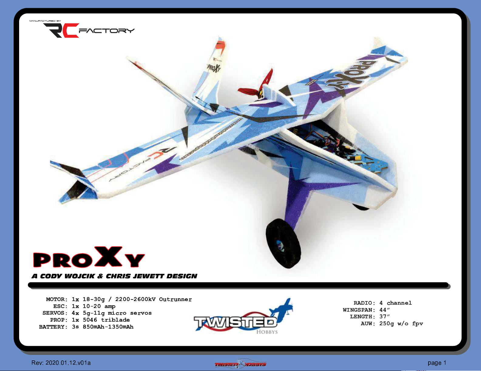
PROXY
A CODY WOJCIK & CHRIS JEWETT DESIGN
☛☞✌☞✍ ✎
✧✦✍✛☞
✳✍☞
✷✸✌✌✦✍✹✎✔✱✒✭✕✪✸
✁
☎✆☎
✂
✄
✦✧★✎✏ ✑
✧✎✬✑✭
✳✎✏ ✑
✆ ✝✆✞✝✞
✏ ✑
☎
✂
✝
✏
✒ ✓✔✕ ✖
✏
✕ ✓✘✕
✏
✏ ✖
✖
✓
✭✕✬✙✢ ✣✮✴
✺✓✏✔✭
✆
✞ ✟
✩✪✫
✗
✮ ✯
✪
✘✘✕
✕ ✓✘✙✕✕✚✛
✣
✰✱✥✣✲✰✱
✵✩✶
✥
✕✪✸
☞ ✜
✢ ✣
✜✤✤✥✣
✺
✍✸✻✼☞✎✬✯✺
✽✼✾✿✧✳✸
❁✦✾✿✌
✸❄✽✎✘✭✕ ✖
✾✎✬✬❀
❂✎✔❃❀
✩✤✤
❅✗✰❆✫
✵
✥
✲
✞
✠✟✡
✁
Page 2
SAFETY NOTES
m
m
m
m
m
m
IMPORTANT: PRIOR TO ANY ASSEMBLY
Please Note: after removing kit from shipping box, lay each piece flat on a
hard surface, this will allow the airframe to straighten out if lightly bent
from shipping. Do not worry since EPP is very pliable and can be bent back
if out of shape.
✁
☎✆☎
✆ ✝✆✞✝✞
☎
✆
✂
✄
✞ ✟
✂
✝
✠✟✡
✁
☎
Page 3

TWISTED HOBBYS
❈ ❉
❊ ❋●❍
❉
■
❏❏❏ ❑
❍❏●❋❍❉▲
▼ ◆❊❊ ❖
❋❑P◆◗
❯
●
❚
❉
❘
❋
◗
❙
■
❍❏●❋❍❉▲
❙❚❉
❋
▼ ◆❊❊ ❖
❋❑P◆◗
Thank you for your purchasing a Twisted Hobbys‘ model. Please read through the entire manu al before beginni ng to
build this model. If you have any questions please contact us at the above indicated email address.
WARNING INFORMATION
This R/C Aircraft is not a toy! Read and understand the entire manual before assembly. If misused, it can cause serious bodily harm and
property damage. Fly only in open areas, and AMA (Academy of Model Aeron autics) approved flying sites. Do not over look the warnings
and instructions enclos ed or those provided by other manufactures’ products. If you are not an experienced pilot and airplane mode ler you
must use the help of an experienced pilot or an authorized flig ht instructor for the building and fly ing of this model aircraf t.
These instructions are suggestions only on how to assemble this model. There are other ways and methods to do so. Twisted Hobbys has
no c ontrol over the final assembly, the materials and accessorie s used when assemb ling this ki t, or the manne r in which the assembled
model, installed rad io gear and electronic parts are used and maintained. Thus, no liab ility is assumed or accepted for any damage
resulting from the use of the assembled model aircraft or from this instruction manual including but not limited to direct, indirect,
incidental, special, and consequential damages. By the act of using this user-assembled pr oduct, the user accepts all resulting li ability. In
no event shall Twisted Hobbys’ liability e xceed the original purchase price of the kit.
SHIPPING DAMAGE
Twisted Hobbys checks each plane before shipping to ensure that each kit is in fine condition. We have no bearing on the condition of any
component parts damaged by use, modification, or assembly of the model. Inspect the components of this kit upon receipt. If you find any
parts damaged or missing, contact Twisted Hobbys immediately. We will not accept the return or replacement of parts on which assembly
work has already begun. Twisted Hobbys reserves the right to change this warranty at anytime without notice.
OUR MISSION
To provide the best products and service to our customers at the lowest prices possible. We take great pride in
our company, our commitment to customer service and in the products we sell. Our online store is designed
to provide you with a safe and secure environment to browse our produ ct catalog.
Thank you for shopping with Twisted Hobbys!
✁
☎✆☎
✆ ✝✆✞✝✞
☎
✆
✂
✄
✞ ✟
✂
✝
✠✟✡
❇
✁
Page 4
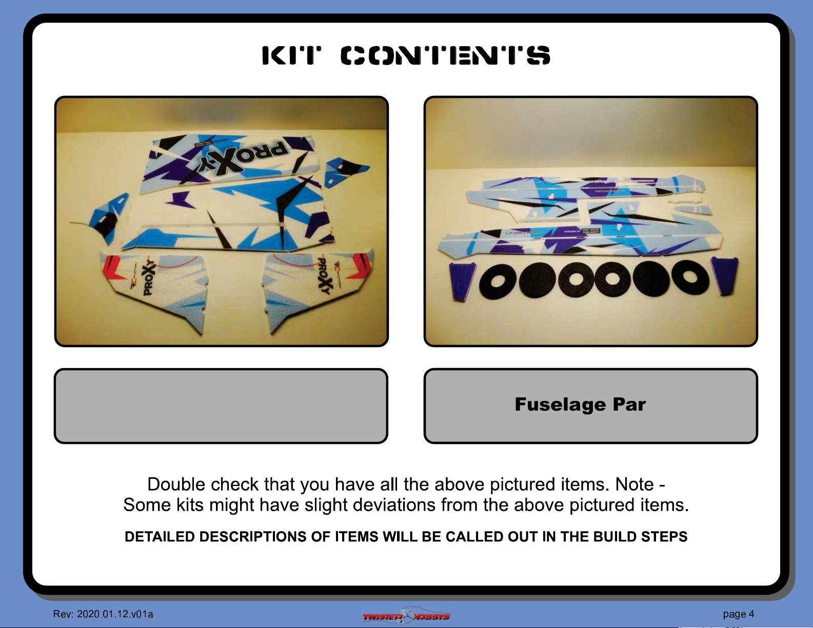
kit contents
Wing Parts
✁
☎✆☎
✆ ✝✆✞✝✞
☎
✆
✂
✄
✞ ✟
✂
✝
Fuselage Parts
✠✟✡
❱
✁
Page 5
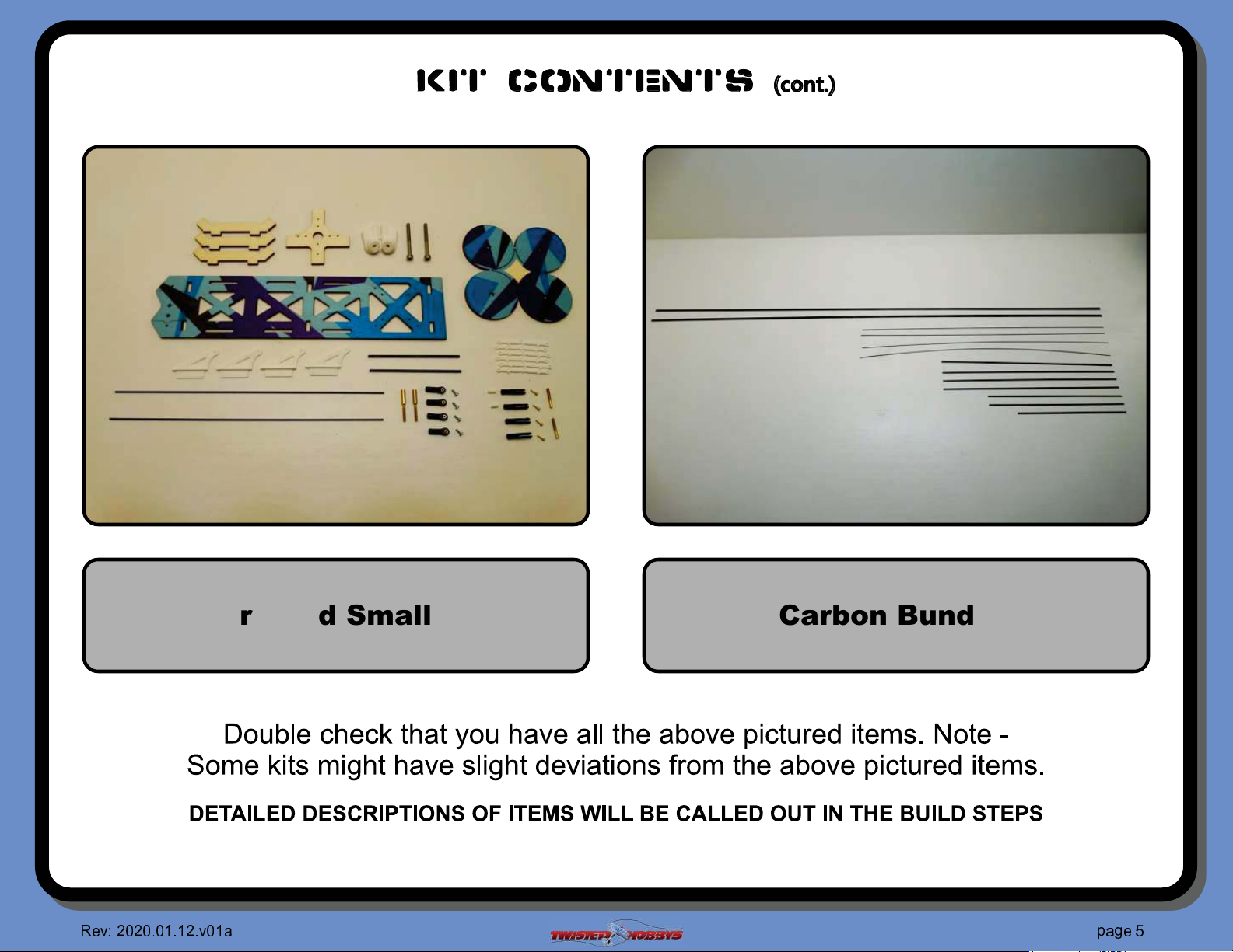
kit contents
❳ ❨
❭ ❪
❫
❩
❬
Carbon BundleHardware and Small Carbon
✁
☎✆☎
✆ ✝✆✞✝✞
☎
✆
✂
✄
✞ ✟
✂
✝
✠✟✡
❲
✁
Page 6
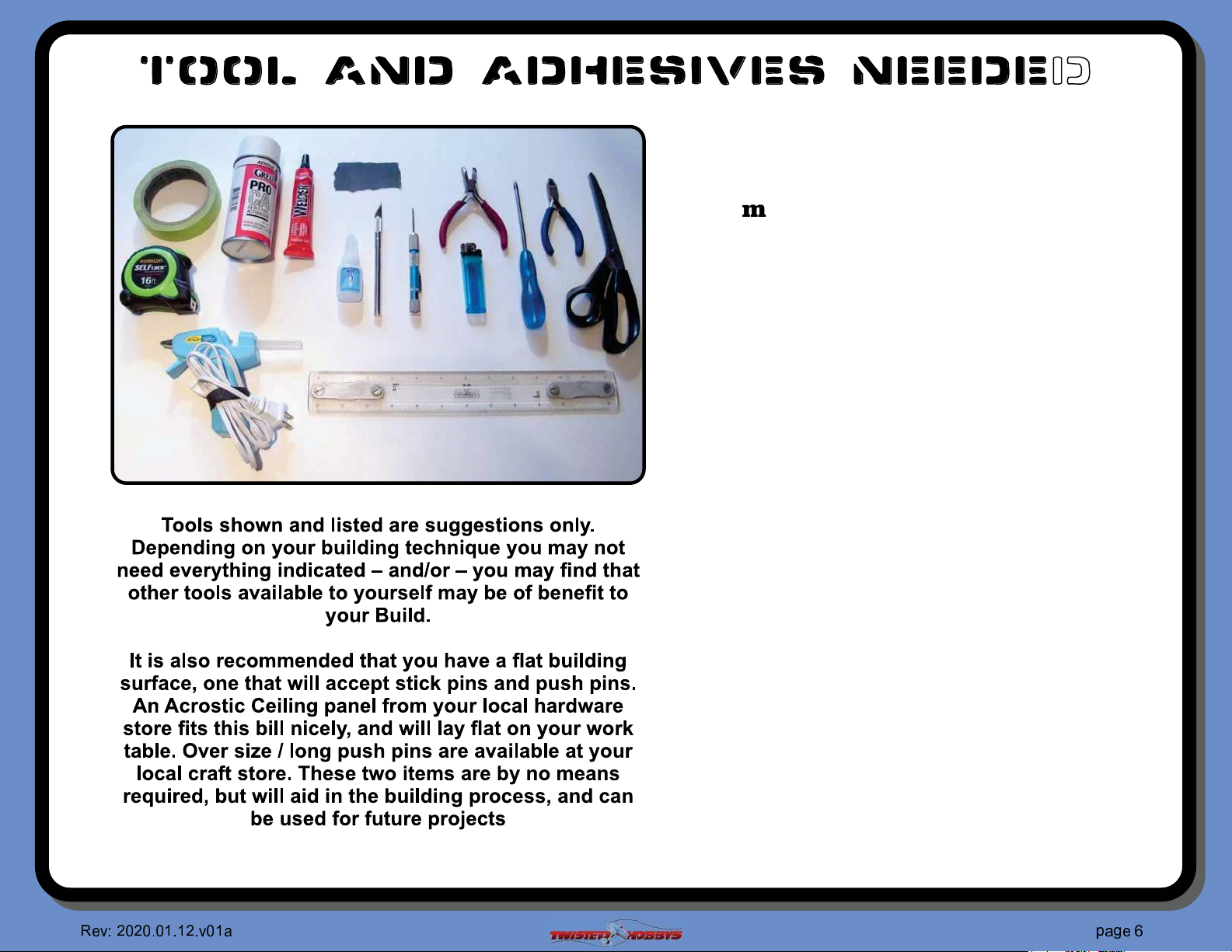
TOOL AND ADHESIVES NEEDED
Ÿ Lighter
Ÿ Small Drill Bits
Ÿ Tape Measure and Ruler
Ÿ Black Sewing Thread
Ÿ Welders or Foam Tac Glue
Ÿ Hobby Knife w/new Blade
Ÿ Needle Nose Pliers
Ÿ Wire Cutters
Ÿ Low Temp Hot Glue Gun
Ÿ Course Sand Paper
Ÿ Scissors
Ÿ Small Phillips Screw Driver
Ÿ Thin and Medium CA
Ÿ CA Applicator Tips
Ÿ Activator
✁
☎✆☎
✆ ✝✆✞✝✞
☎
✆
✂
✄
✞ ✟
✂
✝
✠✟✡
❴
✁
Page 7
the build
CONSTRUCTION METHODS:
Building surface should be at least 2ft x 4ft and "at. Weights or some small heavy objects will be handy for holding things in place
during the time glue is setting.
Welders or FoamTac glue is used for FOAM TO FOAM joints. Thin and Medium CA can be used on the PLASTIC TO FOAM and
CARBON TO FOAM joints. When using the Welders or FoamTac glue for a butt joint, apply a thin "lm to each surface, allow to
sit brei#y per mfg instructions, then assemble. Note that this method will create a nearly instant bond, so locate carefully when
bringing the two pieces together. If alignment is necessary or a slip joint, do not allow the glue to tack up, simple apply and join
immediately, you will have several minutes to locate the two parts before the glue sets up. In most cases the parts being glued can be
handled with care in 30 minutes, full cure is approx 24 hours.
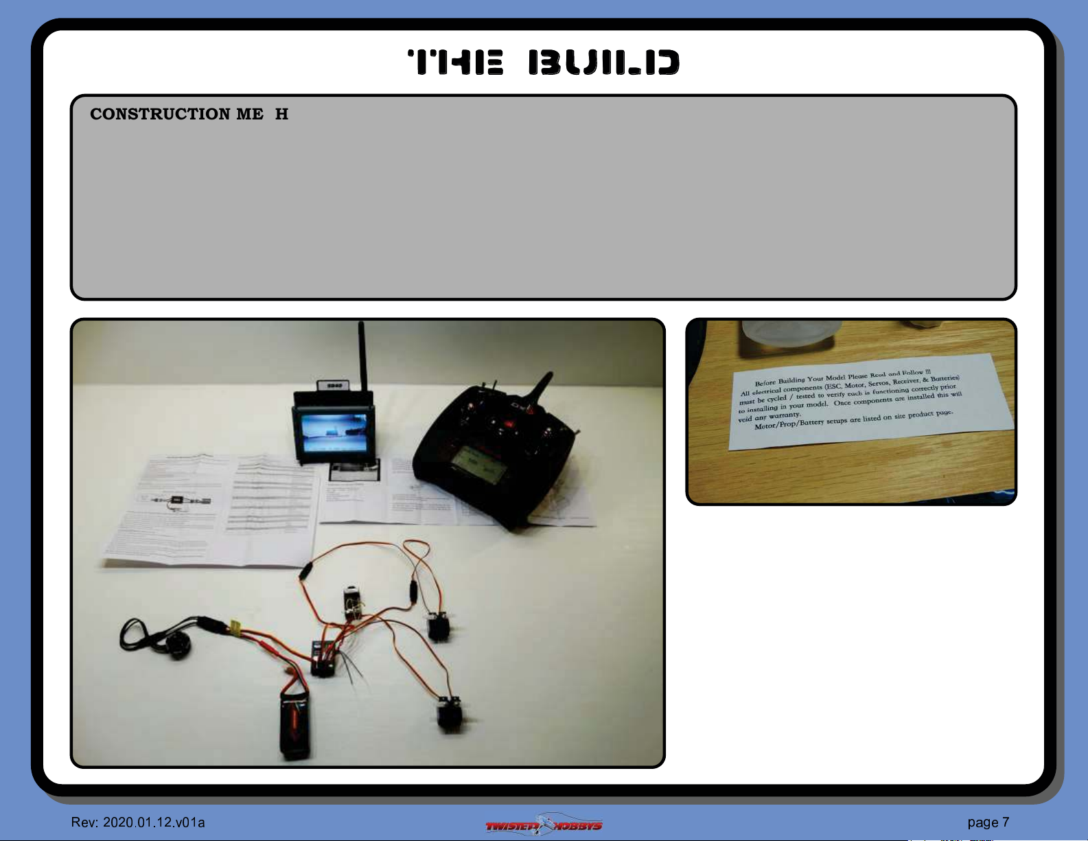
¨ Locate all the electronics that
will be used on this model
¨ Create a model on your
transmitter
¨ Following your radio mfg.
instructions, bind your radio to
the power combo components
¨ Calibrate the ESC.
¨ Con#rm all components work
properly.
✁
☎✆☎
✆ ✝✆✞✝✞
☎
✆
✂
✄
✞ ✟
✂
✝
✠✟✡
❵
✁
Page 8
A B
C
D
E
F G
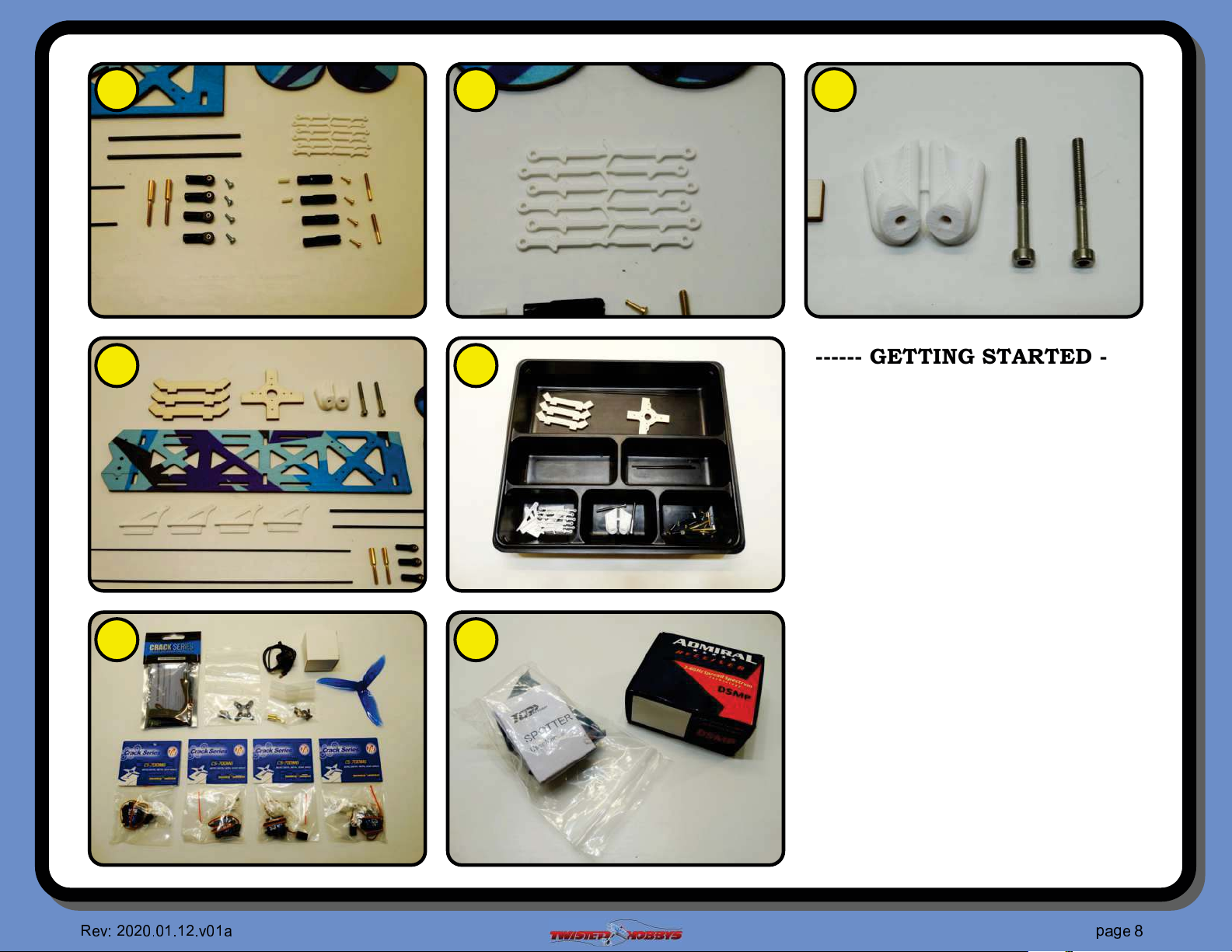
------ GETTING STARTED ------
A Control Rod Ends
B Push Rod Guides
C Landing Gear Components
D Radio and FPV Tray
E Small Parts Organized for Building
F Optional Power Combo
G Basic FPV Components supplied
by Customer
Identify all the components and
pieces shown in the pictures. If there
are any items missing contact Twisted
Hobbys right away. If it looks like
some of the small parts are missing,
double check the hardware bags and
kit box. Note that the items shown in
picture G are customer supplied. FPV
Camera and Receiver with Gyro.
✁
☎✆☎
✆ ✝✆✞✝✞
☎
✆
✂
✄
✞ ✟
✂
✝
✠✟✡
❛
✁
Page 9
A B
C
D
E
F G
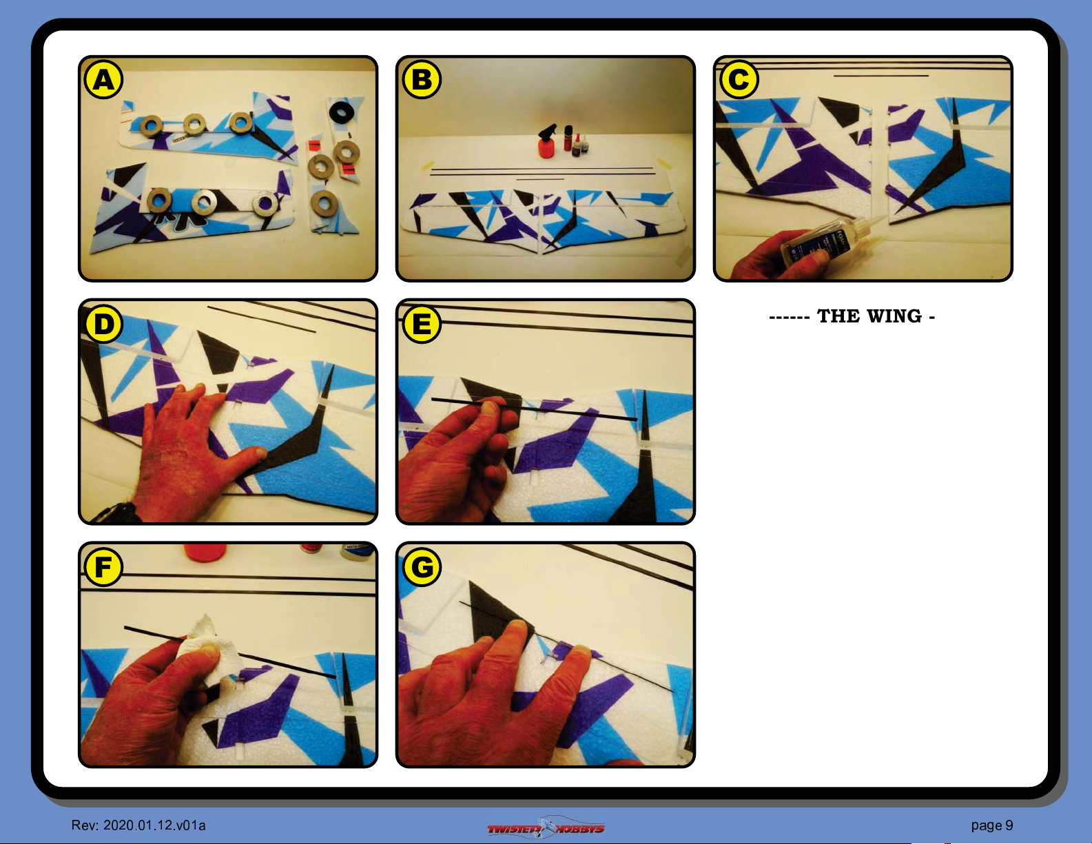
------ THE WING ------
A Gently bend all the control
surfaces back and let them sit like
this for about an hour
B Locate the two longest and largest
spars,1x5x950mm, and the
smaller one that is .5x3x200mm
C Apply a medium layer of FoamTac
to the mating edges of the wing
halves
D Once the glue is tacked up, bring
the two pieces together making
sure the alignment nubs are
locating everything perfectly
E Start with the .5x3x200mm spar
F Wipe it down with alcohol
G Test #t it into the reward slot on
the bottom side of the wing and
secure with thin CA
✁
☎✆☎
✆ ✝✆✞✝✞
☎
✆
✂
✄
✞ ✟
✂
✝
✠✟✡
❜
✁
Page 10
A B
C
D
E
F G
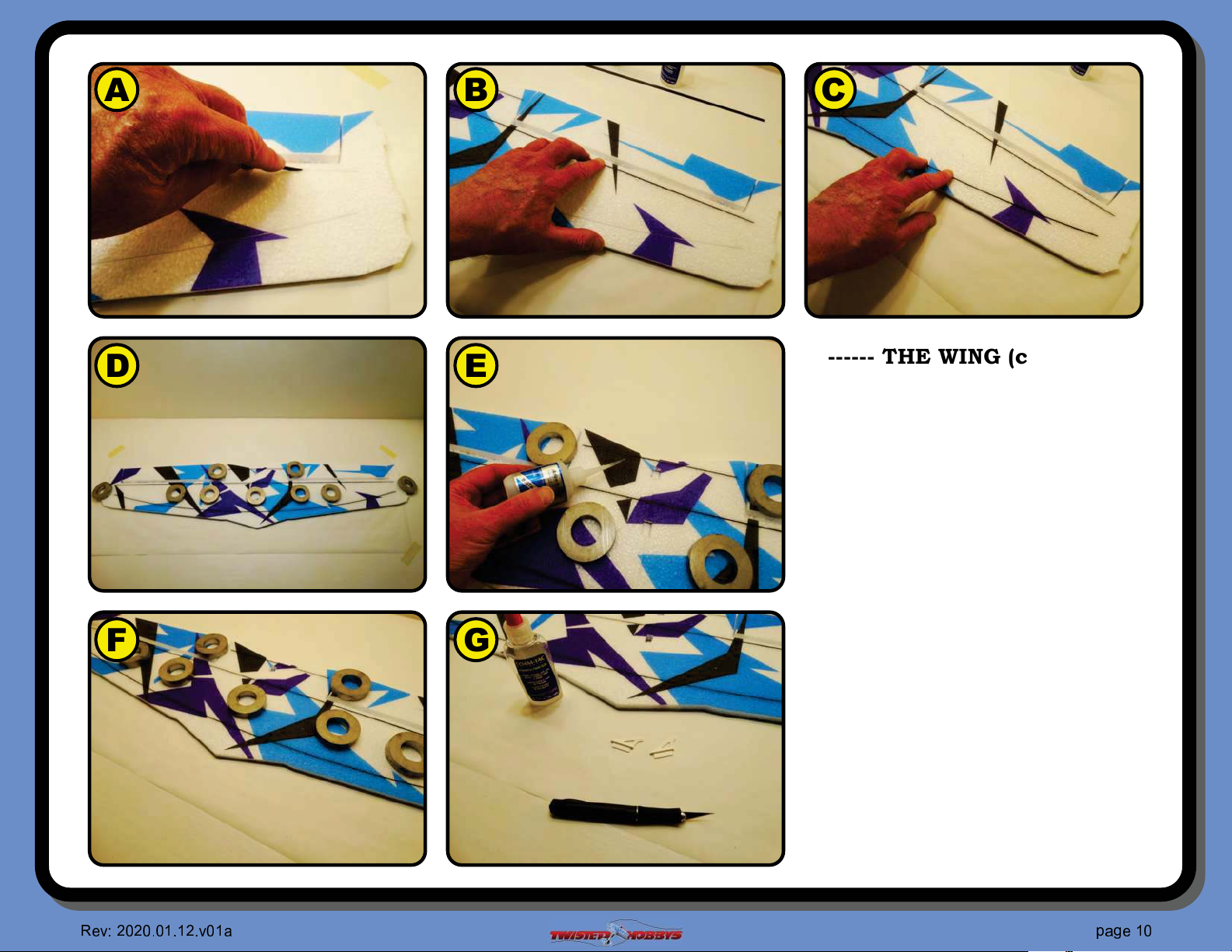
------ THE WING (con’t) ------
Wipe down the two main spars with
alcohol before #tting
A Test #t the rear main spar so that
it is "ush with the surface
B Install the rear main spar,
pushing it "ush to the wing
surface for the how length
C Repeat the process with the forward
main spar
D Secure the wing and spars "ush to
the work bench with some weights
E Glue all the three of the spars to
the wing with some thin CA, don't
hit with kick yet
F Let the whole assembly sit for a
couple minutes to all the CA to
soak in, then hit with kicker
G Locate two of the four control
surface horns. All four are the
same, so any two will do
✞
✁
☎✆☎
✆ ✝✆✞✝✞
☎
✆
✂
✄
✞ ✟
✂
✝
✠✟✡
✆
✁
Page 11
A B
C
D
E
F G
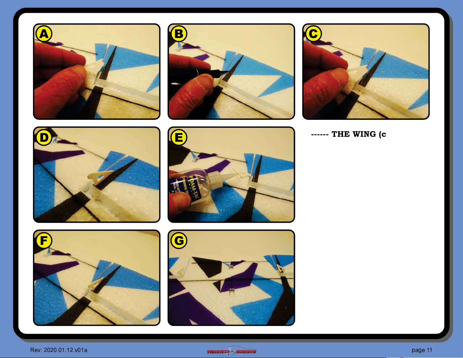
------ THE WING (con’t) ------
FoamTac or CA can be used to attach the
control surface horns
A Test #t the horn in to the provided
slot
B Adjust the length as needed
C Retest the #t
D Make sure the front of the horn is
"ush with the edge of the hinge cut
E Apply some glue to the base of the
control horn
F Install into the slot, again making
sure that the front edge of the
horn is "ush with the hinge cut.
G Repeat for the other side, paying
attention to make sure that the
other horn is installed in the same
location relative to the hinge cut
✞
✁
☎✆☎
✆ ✝✆✞✝✞
☎
✆
✂
✄
✞ ✟
✂
✝
✠✟✡
✞
✁
Page 12
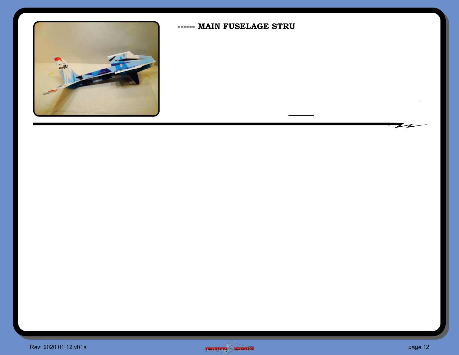
------ MAIN FUSELAGE STRUCTURE / Before you Start ------
If you are an experienced builder all the detail may not be necessary, if so skip
ahead a couple pages.
Building the Main Fuselage structure for the proXy will be similar to that of the Crack
Beaver. There are a couple different ways to do this, method and sequence shown here will
ensure that the X cross section of the fuselage will come out nice and square with little
effort. Things that will be critical to the success of this step will be to make sure ahead of
time that all the slits for the spars are deep enough and clear of nubs so that the spars
will lay into the slits nice and "ush.
IMPORTANT PART FOR SUCCESS OF THIS STEP TO TEST FIT ALL THE PARTS
TOGETHER FIRST AND UNDERSTAND THE SEQUENCE OF EVENTS BEFORE
GLUING.
------ THE PROCESS / words ------
Ÿ Start by rounding up the two main fuselage pieces
Ÿ Remove any scrap from the cut out areas
Ÿ Locate the fuselage section that has the LONG slits and SHORT tabs as shown
Ÿ Split the tabs in half at the $V$ marks
Ÿ Locate the landing gear struts. Note that they are keyed unique
Ÿ Test #t that the nubs match up perfectly and that the slits for the spars align
Ÿ Attach the two pieces with FoamTac, using the $tackup$ method
Ÿ Hold a little pressure for a minute or two against the joint while the glue sets up
Ÿ Repeat for the other side
Ÿ Locate the Ele/Rud that is keyed to #t the large one piece fuselage section
Ÿ Glue the two together with the $tackup$ method, make sure the slits align
Ÿ Hold a little pressure for a minute or two against the joint while the glue sets up
Ÿ Take one of the two smaller carbon spars and clean it with alcohol
Ÿ Fit it into the slit of the Ele/Rud piece that was just attached, make sure it is "ush
Ÿ Constrain it "at and then CA in place
Ÿ Take the other smaller spar and the loose piece of the Ele/Rud
Ÿ Clean, test #t, constrain and CA glue the two together
Ÿ Get two of the larger spars and the one piece fuselage side
Ÿ Clean the spars with alcohol and test #t, make sure that the spar is all the way to the top of the slit and "ush
Ÿ Also check that the remaining part of the spars at the end of the strut will be approximately the right length to engage the axle hubs
Ÿ Do not glue the hubs on yet, they will get attached in a later step
Ÿ Constrain, check for "ush and CA
Ÿ Take top half of fuselage and the remaining two larger carbon spars
Ÿ Test #t them into the slits, again make sure that they go all the way to the upper end of the slit
Ÿ Make sure they are "ush, the constrain it all "at and apply CA
Ÿ Test #t the last remaining smaller spar into the slit in the Ele/Rud
Ÿ Constrain, check for "ush and CA
✞
✁
☎✆☎
✆ ✝✆✞✝✞
☎
✆
✂
✄
✞ ✟
✂
✝
✠✟✡
☎
✁
Page 13

----- THE PROCESS / words (con’t) -----
The next several steps will all be done WITHOUT GLUE it is for test "tting only and to
understand how the assembly will go together, study the pictures and make sure everything
"ts together nicely
Ÿ Take the top half of the fuselage with the spars sticking out and feed those spar ends thru the cut outs in the fuselage
Ÿ Get it pretty close to the tabs, then focus your attention the the rear Ele/Rud spar and feed it thru its associated hole
Ÿ Fully engage all the tabs and slots
Ÿ Make sure that the bevels on the top of the fuselage are LEVEL, if they are not, you have assembled the pieces incorrectly
Ÿ Grab the lower fuselage half and align the tabs at a slight angle to the slots in the fuselage
Ÿ Engage the tabs into the slots at the same time as guiding the carbon spars into their respective slits
Ÿ Push everything together, making sure that it all #ts nice, "ush and square
Ÿ If any parts are not "ush, fully engaged or not square, make the necessary adjustment to get everything #tting properly
This completes the TEST FIT WITH NO GLUE, keep in mind how it all went together and
disassembly all the pieces
Ÿ Start the reassembly with the main fuselage piece and the top half of the other side of the fuselage
Ÿ Apply FoamTac to the larger piece in all the areas where the two items will contact each other including the tab and slot
areas
Ÿ Keep glue AWAY from the area where the spars cross thru
Ÿ Fit the upper fuselage half and the strut spars thru the holes in the large fuselage piece like was done in the test #t up
Ÿ Make sure all the foam tabs and slots are fulling engaged and that the strut spars and Ele/Rud spar are in their slits and
"ush
Ÿ Make sure the two upper fuselage member are nice and square with each other
Ÿ Apply a little pressure to the assembly for a couple minutes to allow the FoamTac to make a good bond
Ÿ Next the lower fuselage half will be attached, apply FoamTac to all the mating FOAM surfaces
Ÿ DO NOT PUT GLUE THE SPARS AT THIS TIME
Ÿ Move the two pieces into position as was done with the #t up
Ÿ Make sure the foam tabs and slots are fully engaged
Ÿ Double check that the spars are (dry #t) "ush with the surface of their slits
Ÿ Make sure all the fuselage pieces are 90 degrees to each other along the entire length
Ÿ Hold a little pressure on the two pieces for a minute or two so that the FoamTac can make a good bond
Ÿ NOW the spars will be secured with CA to their slits
Ÿ Make sure that all the fuselage components are still square and that the spars are "ush in the slits
Ÿ Apply thin CA to all the spars and hit with kicker
This completes the Main Fuselage Structure
✞
✁
☎✆☎
✆ ✝✆✞✝✞
☎
✆
✂
✄
✞ ✟
✂
✝
✠✟✡
❇
✁
Page 14
A B
C
D
E
F G
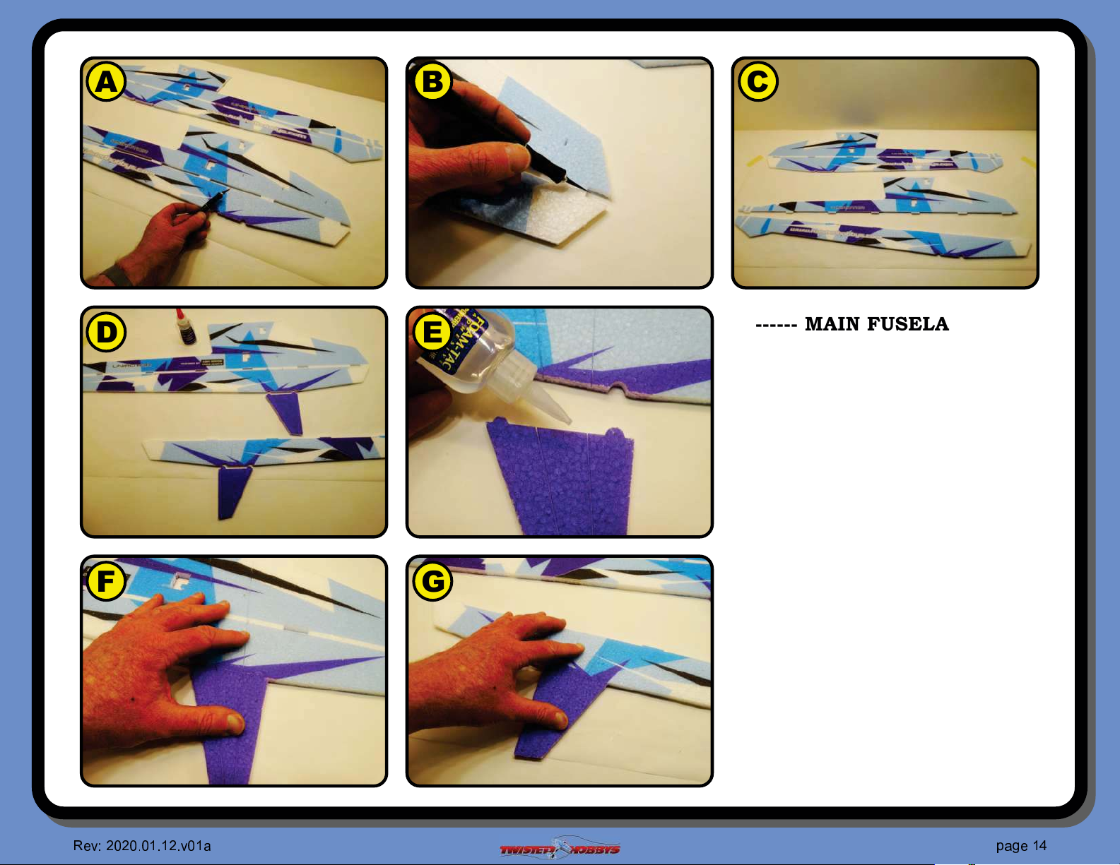
------ MAIN FUSELAGE ------
Pictures to follow along with for the
previous two pages
A Locate the two fuselage halves
bottom one shown gets split ...
B ... at the center of the tabs
C Split all the way, nose to tail
D Locate the gear struts and notice how
they are keyed to their mate fuselage
piece
E Use the “tack” up method to
attach the gear strut to the
fuselage
F Assemble and hold pressure for a
minute or so
G Repeat for the other side
✞
✁
☎✆☎
✆ ✝✆✞✝✞
☎
✆
✂
✄
✞ ✟
✂
✝
✠✟✡
❱
✁
Page 15
A B
C
D
E
F G
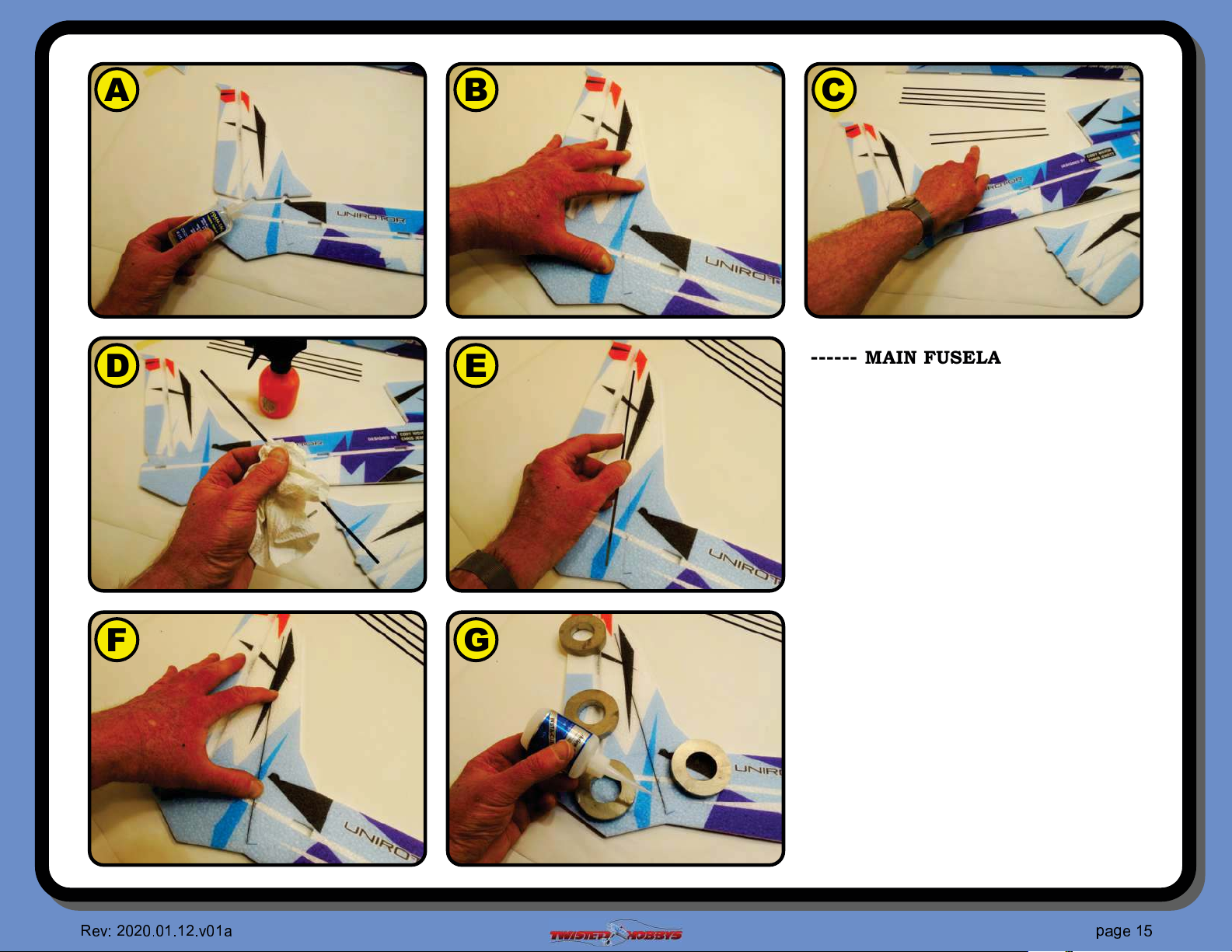
------ MAIN FUSELAGE (con’t) ------
A Find the rudder piece shown that
is keyed to #t the fuselage on that
side
B Using the “tack” method attache the
two pieces
C Locate the shorter spars from the set
pictured above (.5x3x250mm)
D Wipe it down with alcohol to remove
any mfg residue
E Test Fit and clean up the slot if
needed
F Install / Insert
G Constrain "at and secure the spar
and control surface together with
some thin CA and kicker
✞
✁
☎✆☎
✆ ✝✆✞✝✞
☎
✆
✂
✄
✞ ✟
✂
✝
✠✟✡
❲
✁
Page 16
A B
C
D
E
F G
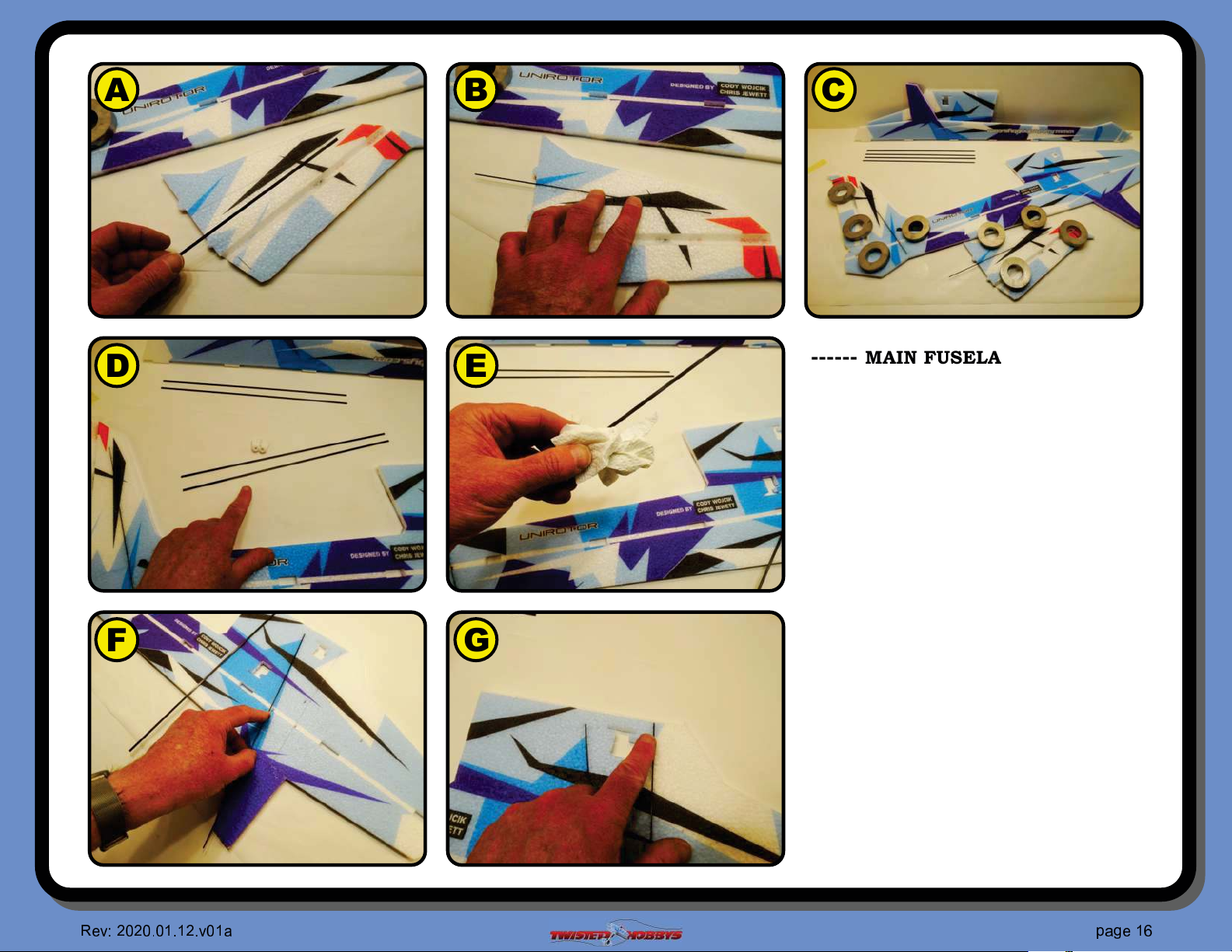
------ MAIN FUSELAGE (con’t) ------
A Locate the other short spar, prep it
and ...
B ... test #t it, as was done with the
other one
C Constrain and combined with CA and
kicker
D Locate two of the four longer spars
(.5x3x332mm long)
E Prep them
F Test #t them
G Make sure the go all the way up to
the top of the slot near the wing
saddle part of the fuselage
✞
✁
☎✆☎
✆ ✝✆✞✝✞
☎
✆
✂
✄
✞ ✟
✂
✝
✠✟✡
❴
✁
Page 17
A B
C
D
E
F G
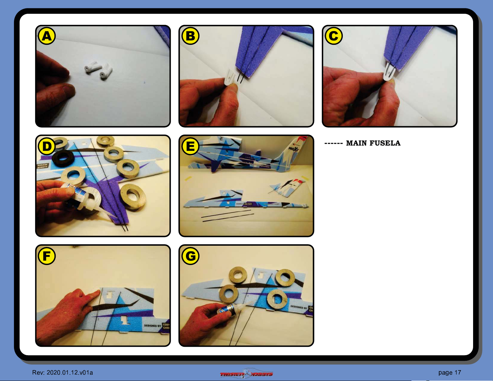
------ MAIN FUSELAGE (con’t) ------
A Locate the two little white 3D printed
axle hubs
B Compare the slots in the hub to the
exposed spars
C The two should match up pretty
close, if not double check to make
sure the spar is up against the other
end of the slot
D Constrain Flat and secure with thin
CA and kicker
E Grab the remaining two spars
(.5x3x332mm) and the top half of the
other fuselage side
F Test #t them, all the way up to the
wing saddle like was done with the
other side
G Constrain "at and secure with
thin CA and kicker
✞
✁
☎✆☎
✆ ✝✆✞✝✞
☎
✆
✂
✄
✞ ✟
✂
✝
✠✟✡
❵
✁
Page 18
A B
C
D
E
F G
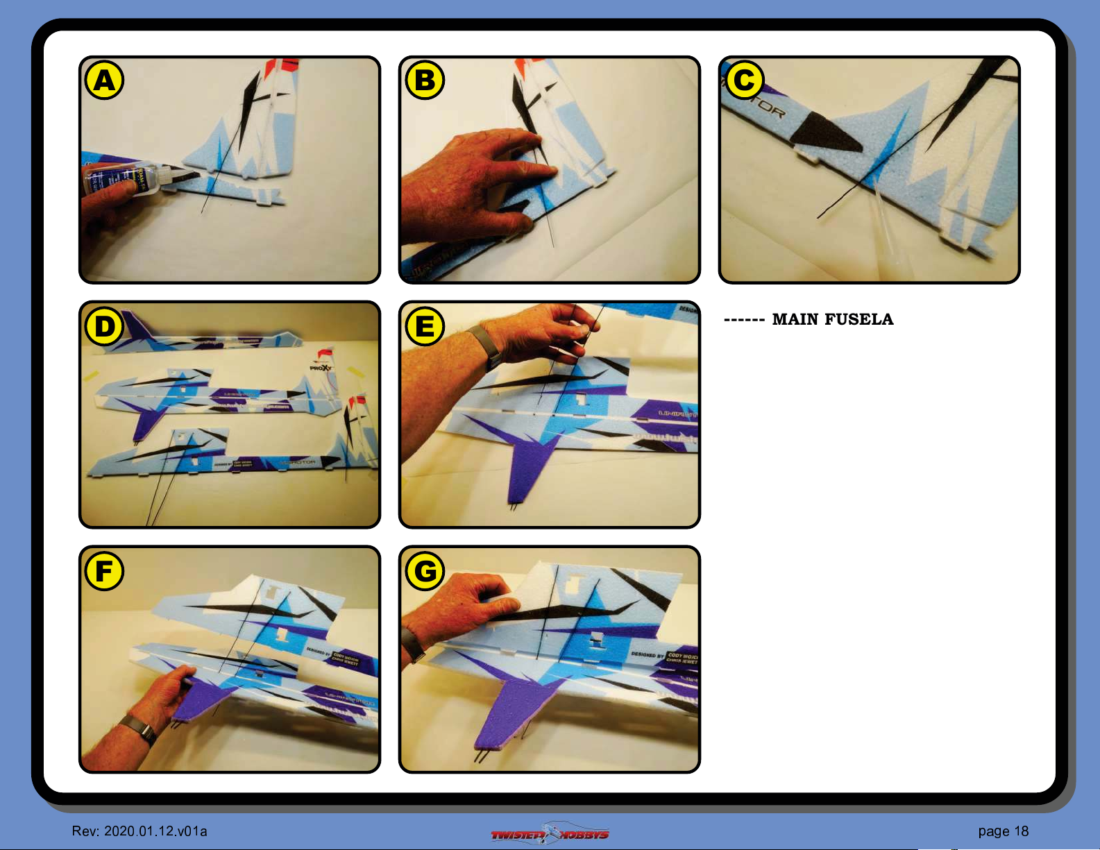
------ MAIN FUSELAGE (con’t) ------
A Use the “tack” method and attach the
tail piece shown, only apply the glue
on the foam-foam part of the joint
B Hold pressure for a minute or so
C Secure the carbon-foam part of the
joint with thin CA and kicker
D Finished parts
THIS IS WHERE TEST FITTING
STARTS - DO NOT USE GLUE UNTIL
CALLED FOR
E Take the fuselage piece with the spars
sticking ut and thread the ends thru
the other fuselage part
F All the way thru...
G .... and line up the tabs
✞
✁
☎✆☎
✆ ✝✆✞✝✞
☎
✆
✂
✄
✞ ✟
✂
✝
✠✟✡
❛
✁
Page 19
A B
C
D
E
F G
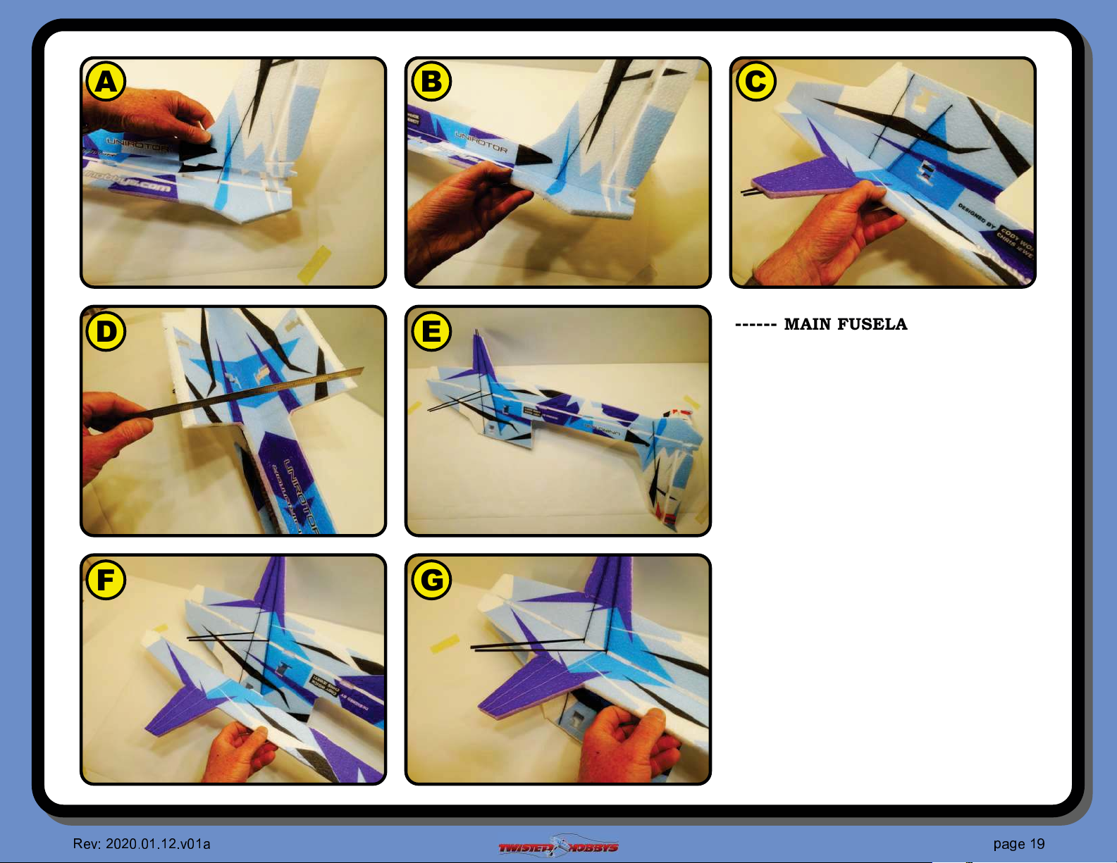
------ MAIN FUSELAGE (con’t) ------
A Also feed the extended tail spars thru
their respective cut outs
B Fully engage the tail tabs
C Fully engage the forward tabs
D Check that the fuselage saddle area
is approximately level/horizontal
E Flip the fuselage assembly over so
that the extended spars are facing
upward
F Grab the mating lower fuselage
section and start to line up the tabs
into their cutouts and the spars into
their slots
G You will have to #t them up to
each other initially at a little bit of
an angle, once the tabs and spars
are nearly in position, you can
square things up
✞
✁
☎✆☎
✆ ✝✆✞✝✞
☎
✆
✂
✄
✞ ✟
✂
✝
✠✟✡
❜
✁
Page 20
A B
C
D
E
F G
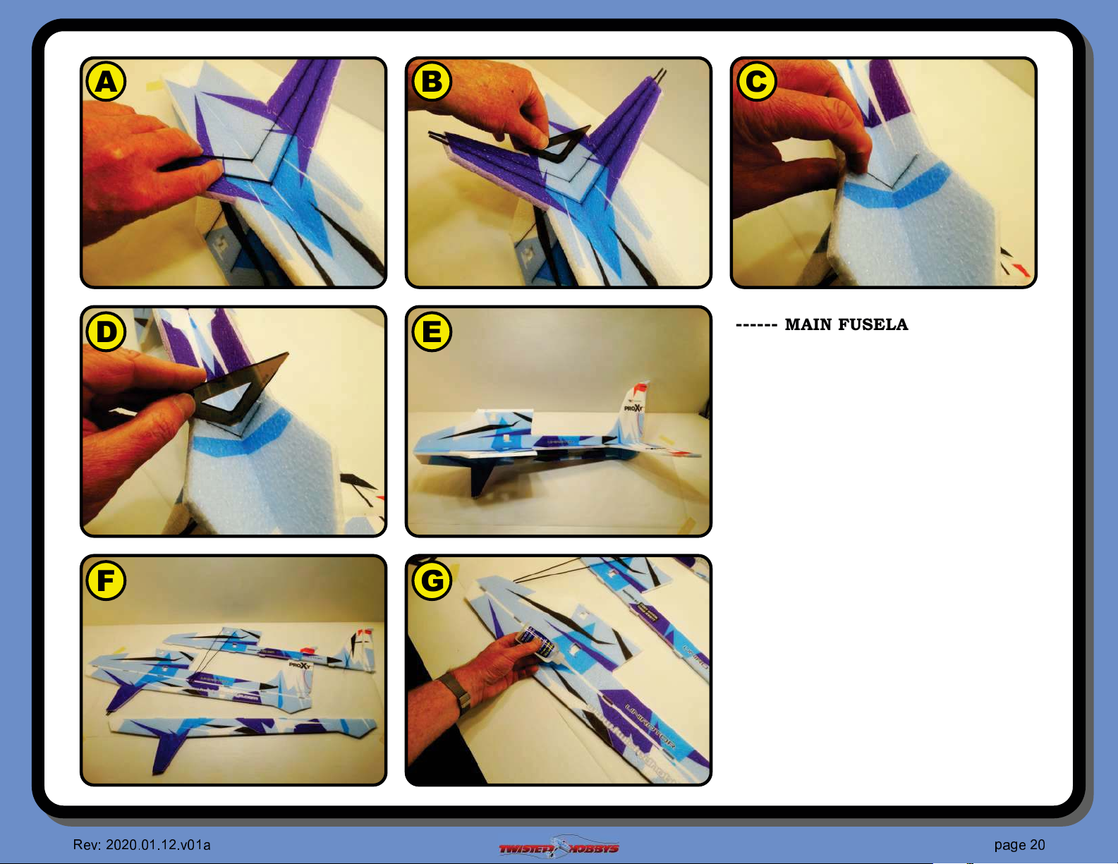
------ MAIN FUSELAGE (con’t) ------
A Fully seat the spars land gear struts
into their slots, make sure they are
"ush
B Check to make sure the two fuselage
members are square to each other in
and around the landing gear strut
area
C Fully seat the tail spars into their
slots, make sure they are "ush
D Check to make sure the two fuselage
members are square to each other in
and around the tail section
E TEST FIT UP is essentially done, have
a look at the whole thing and make
sure it all looks nice and square
F Take is all apart, remember how it
had all been test #t assembled
TEST FIT IS DONE - TIME FOR GLUE
G Apply glue as shown to all mating
surfaces
☎
✁
☎✆☎
✆ ✝✆✞✝✞
☎
✆
✂
✄
✞ ✟
✂
✝
✠✟✡
✆
✁
Page 21
A B
C
D
E
F G
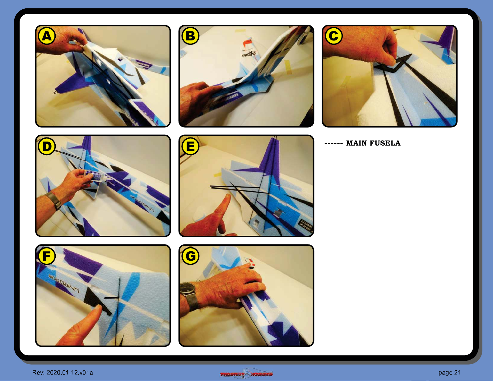
------ MAIN FUSELAGE (con’t) ------
A Feed the spars thru the forward
section
B Feed the spars thru the tail section
C Check for squareness and that all the
joints are #rm against each other
D Apply glue to lower fuselage sections
E Keep the two long extended spars free
of glue at this time
F Keep the single extended tail spare
free of glue as well
G Press all the FoamTac joints together
#rmly for a minute or two or until
they hold their own position
☎
✁
☎✆☎
✆ ✝✆✞✝✞
☎
✆
✂
✄
✞ ✟
✂
✝
✠✟✡
✞
✁
Page 22
A B
C
D
E
F G
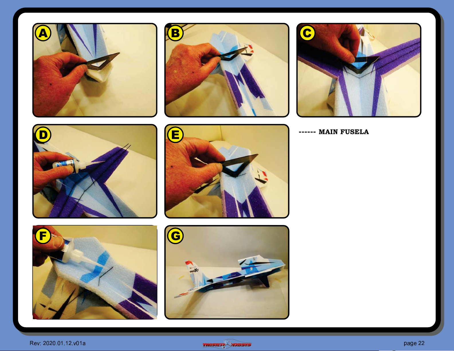
------ MAIN FUSELAGE (con’t) ------
A Check that the fuselage is square all
along the length nose to...
B ... tail
C From the underside, speci#cally
check that all the spars for the
landing gear struts are "ush
D When satis#ed, secure the one that
have not been glued yet with some
thin CA
E Repeat step C for the area of the tail
section where the spars comes thru
F Repeat step D for the tail
G Do one last double check with your
builder square to make sure
everything is nice and square and set
aside for now to let the glue cure up.
MAIN FUSELAGE STRUCTURE IS NOW
COMPLETE
☎
✁
☎✆☎
✆ ✝✆✞✝✞
☎
✆
✂
✄
✞ ✟
✂
✝
✠✟✡
☎
✁
Page 23
A B
C
D
E
F G
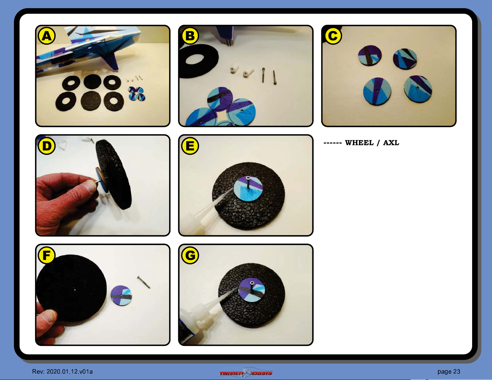
------ WHEEL / AXLES/ HUBS ------
A Gather up all the round wheel donuts
B Locate the two 3D printed axle hubs,
the socket head cap screws and the
wood hub caps
C Separate the hubs from their wooden
tree
D Take one of the hub caps, one of the
cap screw and a solid wheel piece
E Fit them together, using the cap
screw as a locator to position the hub
cap at the center of the foam wheel
piece. Secure with CA or FoamTac
F Flip the tire piece over...
G ... and repeat for the other side
☎
✁
☎✆☎
✆ ✝✆✞✝✞
☎
✆
✂
✄
✞ ✟
✂
✝
✠✟✡
❇
✁
Page 24
A B
C
D
E
F G
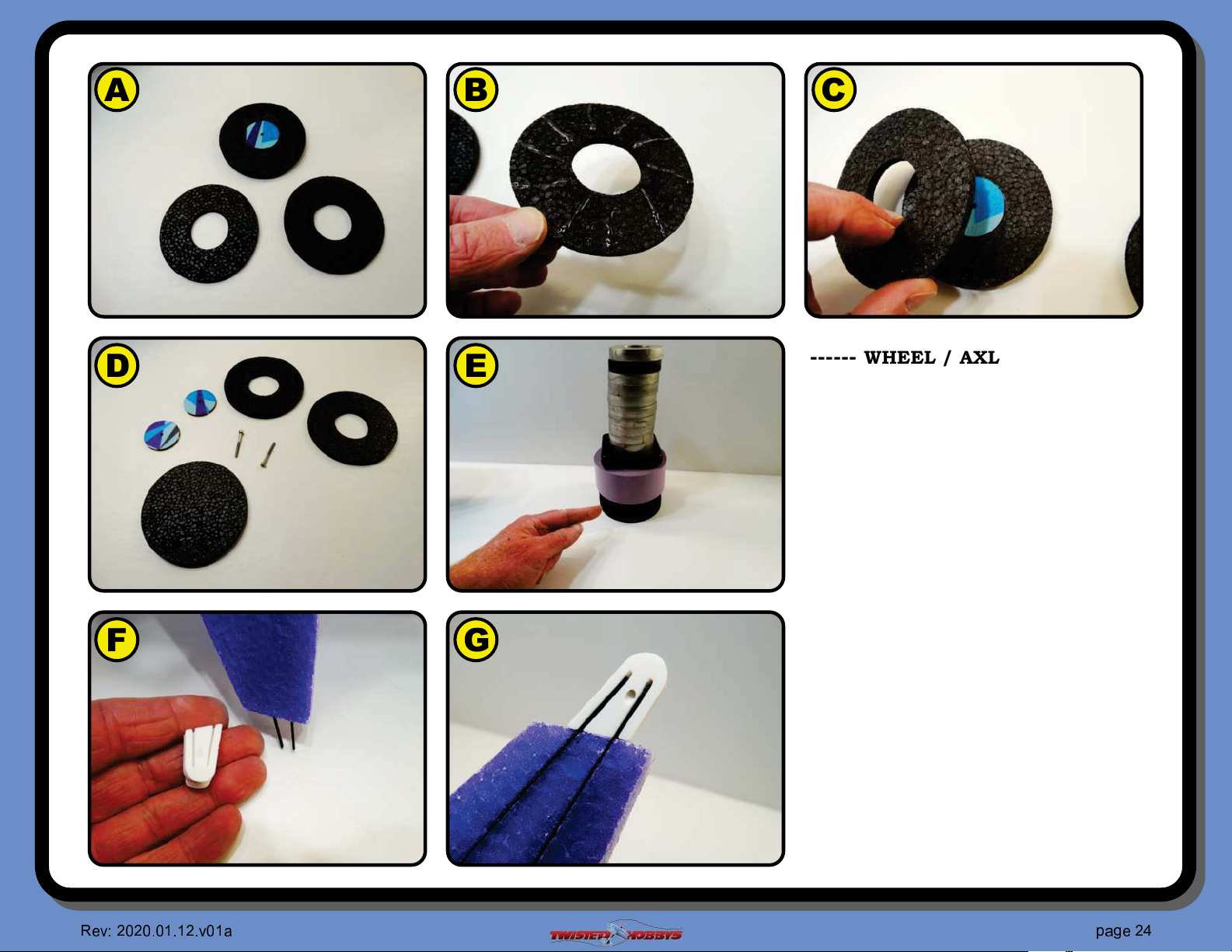
------ WHEEL / AXLES/ HUBS ------
A Gather up all two of the donuts with
holes in the center as pictured
B Apply some FoamTac to one side
C Join together with the piece that has
the wood hub cap all ready attached
to it, center the hole around the hub
cap. When joining together slightly
twist the two pieces to distribute the
glue
D Repeat for the other wheel
E Once both wheels are built, put them
under some heavy weights, and leave
them there overnight, this will
minimize the edges from curling up
F Locate the 3D printed axle hubs
G ... and test #t them both on to the
exposed ends of the spars as shown,
the spars may need to be shortened
slightly for a nice "ush #t
☎
✁
☎✆☎
✆ ✝✆✞✝✞
☎
✆
✂
✄
✞ ✟
✂
✝
✠✟✡
❱
✁
Page 25
A B
C
D
E
F G
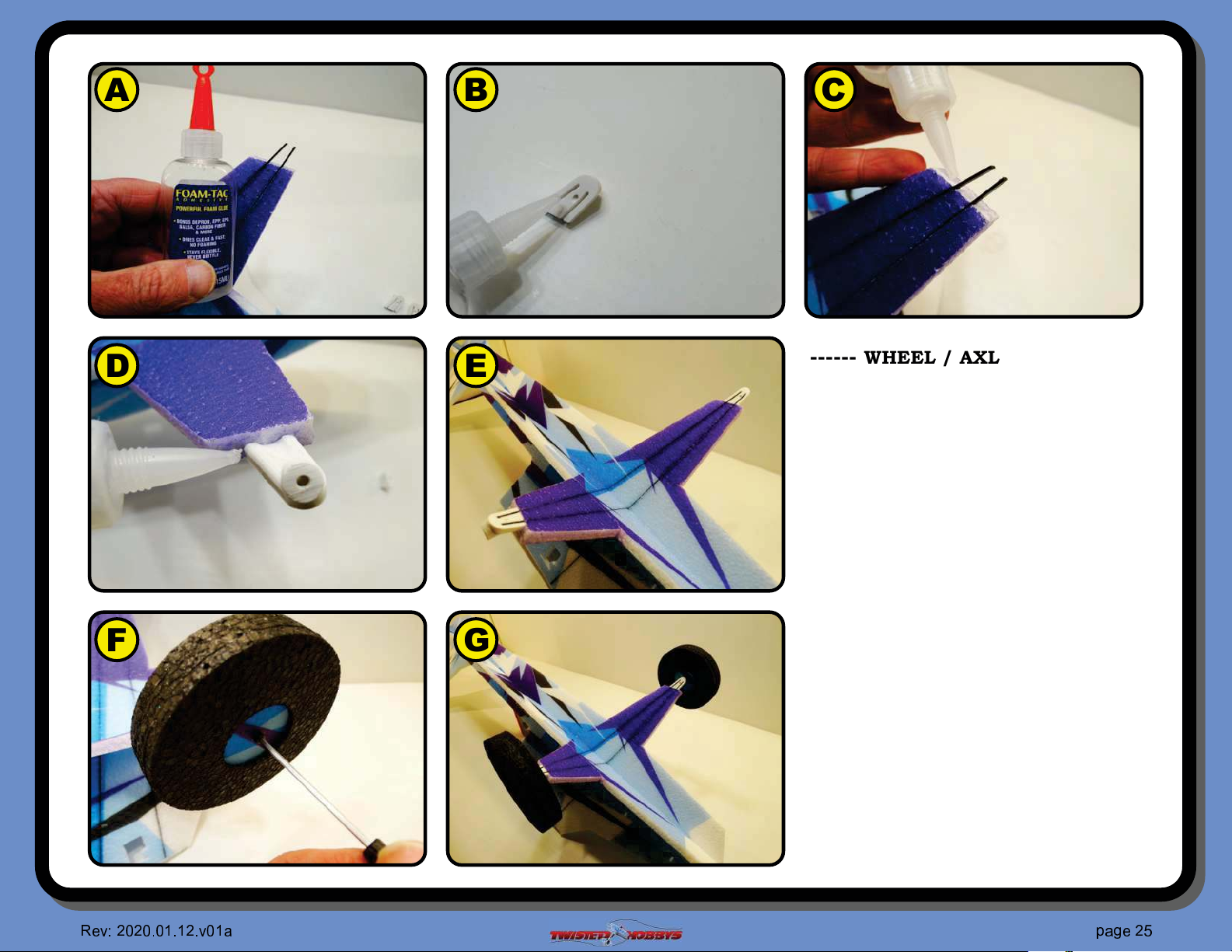
------ WHEEL / AXLES/ HUBS ------
A For best strength and longevity, use
FoamTac for attaching the axle hubs
B Put some glue in the grooves
C Coat the spars
D Join the two pieces as shown and
add a #let of glue all around the base
of where the two pieces meet. Make
sure the spars are "ush and that the
axle hub is #rm against the bottom
edge of the landing gear strut
E Repeat for the other side. Let this
assembly dry at least overnight before
attempting to attach the wheels
F Insert a cap screw thru the wheel and
thread into the axle hub. Note that it
may be a little tight, so work the
screw in gently by going in and out a
little at a time.
G ... and repeat for the other side
☎
✁
☎✆☎
✆ ✝✆✞✝✞
☎
✆
✂
✄
✞ ✟
✂
✝
✠✟✡
❲
✁
Page 26
A
C
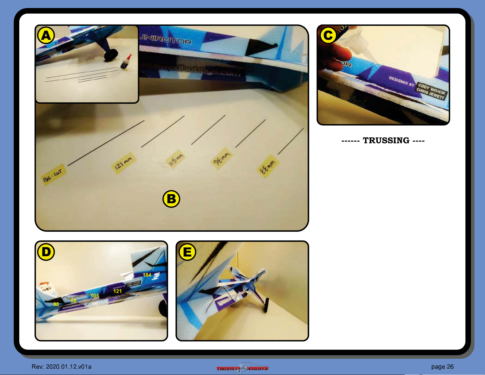
------ TRUSSING ------
A Gather up two of the four long skinny
round carbon rods (1x500mm) and
the two thicker ones from the
hardware kit that are approx.
1.2x184mm long
B
B Cut one of the 500mm long pieces
into one each of: 121/105/98/88 mm
long pieces
C Locate the slit cuts in the fuselage
pieces that are angled to accept the
ends of the rods just cut, #ll each of
the slots on one side with FoamTac
D
E
D Install the trussing as show, starting
❝❞❡
✐
❞
❞
❝❣❤
❞
❝❢❝
with the longest (thick one) that goes
from the wing saddle down to the
fuselage, from there they zig-zag
towards the rear of the fuselage in
decreasing size.
E Make sure the fuselage is true, and
repeat the process for the other side
☎
✁
☎✆☎
✆ ✝✆✞✝✞
☎
✆
✂
✄
✞ ✟
✂
✝
✠✟✡
❴
✁
Page 27
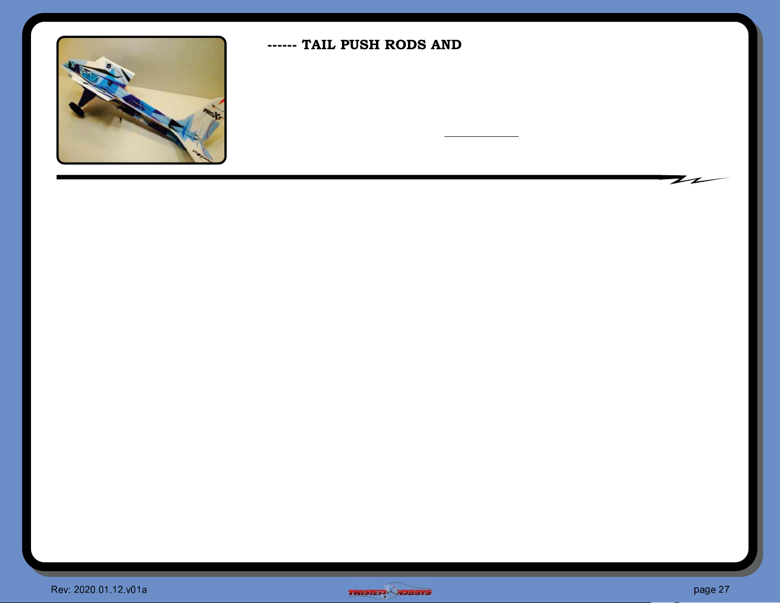
------ TAIL PUSH RODS AND SERVOS / Before you Start ------
If you are an experienced builder all the detail may not be necessary, if so skip ahead a couple pages.
Following is the process for the installation of the equipment tray, the dry #tting (no glue) of the servos, and the
building (and installation) of the tail control rods. Read ahead a couple steps along the way if the assembly
process is not clear on the current step.
CAUTION SHOULD BE USED WHEN BUILDING THE CONTROL RODS.
IT IS CRITICAL
FOR THESE STEPS THAT THE SERVOS AND CONTROL SURFACES BE CENTERED. IF YOU DO NOT
HAVE THINGS CENTERED YOUR CONTROL RODS WILL END UP THE WRONG LENGTH!
------ THE PROCESS / words ------
Ÿ Start by locating the three wood cross braces, the equipment tray and your four servos
Ÿ Separate the wood pieces from each other
Ÿ Test #t them into the slots of the equipment tray
Ÿ Wiggle the three wood cross braces into their respective holes in the fuselage
Ÿ Fit the equipment tray onto the cross braces
Ÿ Use thin CA to attach the wood pieces in the tab areas
Ÿ Underneath on the foam side the tabs should be "ush adjust if needed then CA
Ÿ Push the four servos into their cut out, pay attention the the orientation. Horns for the ailerons will face outward, and horns for the tail will face inward
Ÿ Do not glue the servos yet, but situate them so that the ailerons servos are "ush with the inner fuselage wall and the tails servos should be "ush with
the external fuselage wall
Ÿ Locate the two remaining control surface horns and test #t them into their pre-cut slots
Ÿ The fore/aft location should be such that the hole in the horn is directly above the hinge line.
Ÿ The slot in the foam should already be cut to locate this as needed, but it does not hurt to double check
Ÿ Once happy with the #t remove the horns, put some FoamTac in the slot, some FoamTac on the tab of the horn and install
Ÿ Repeat this for the other side
Ÿ Locate all the control rod guides and cut them free from each other
Ÿ Install them into their tiny holes on the $top-inside$ of the fuselage, DO NOT GLUE THEM YET
Ÿ Locate two clevis and two ball link sets of hardware, and the two remaining long thin rods
Ÿ The clevis end will install on the control surface side of the push rod, and the ball link end will attach to the servo horn
Ÿ Locate the two tiny white spacers and #nger install them into the back of one of the ball link ends
Ÿ Once you have it started by hand, hold the ball link with some small pliers and gently tap the white spacer in a little further
Ÿ When completely seated there should be just a little white of the spacer showing
Ÿ Test #t one end of the push rod into the center of the white spacer that was just installed. You may need to dress up the end of the carbon rod a little so
that it #ts cleanly into the center of the spacer
Ÿ Once happy with the #t, use some thin CA to secure the pieces together
Ÿ Repeat for the other control rod
Ÿ Next from the nose of the aircraft, thread the control rod thru the push rod guides such that when completely threaded thru, the ball link should be near
the area of the servo control horn
Ÿ The ball link will attach to the BOTTOM of the servo horn. You will need to manipulate the servo out of it's pocket a little to be able to reach the tiny
screw that threads into the base of the ball part of the link. Use a little bit of thread locker on the screw to keep it from backing out
Ÿ Repeat this process with the other control rod and servo
Ÿ Locate two of the clevis links and two of the small threaded rod ends
Ÿ Thread the clevis on the threaded rod end for approx half of the available threaded length. Do this for both pieces.
☎
✁
☎✆☎
✆ ✝✆✞✝✞
☎
✆
✂
✄
✞ ✟
✂
✝
✠✟✡
❵
✁
Page 28
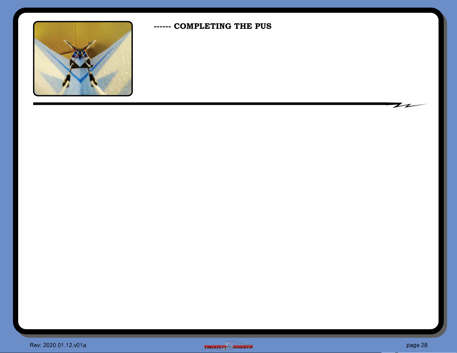
------ COMPLETING THE PUSH ROD LENGTHS AND ENDS ------
MAKE SURE THAT WHEN CALLED FOR THAT THE
SERVOS ARE ELECTRONICALLY CENTERED AND
THE CONTROL SURFACES ARE “LOCKED” IN
THEIR NEUTRAL POSITIONS
------ THE PROCESS / words (con’t) ------
Ÿ
Center the servos
Ÿ Constrain the control surfaces to neutral
Ÿ Attach a clevis to one of the control surface horns, make sure the little brass pin gets snapped in all the
way. It may be necessary to clean the hole out in the control surface horn if the brass pin does not pass
thru. If it does need to be enlarged, the tip of a hobby knife or 1mm drill (.039in) can be used, just be
careful to not make the hole oversize, this will cause slop in the linkage
Ÿ Align the raw push rod end and the brass part of the clevis assembly, you should notice that there is
some extra length on the rod. Double check that everything is still centered and neutral
Ÿ Cut the control rod with a small pair of snips right at the place were the threads start (see photo)
Ÿ Dress up the end of the rod to make it nice and smooth, remove the constraints from the control surface,
"ex the control surface so that you can install the end of the rod into the open end of threaded brass
piece.
Ÿ Return the control surface to neutral by pushing/pulling the control rod a little in or out to get the
control surface to neutral. Make sure the servo is still centered as well
Ÿ Once you like the location, secure with thin CA. For added security you and also make small crimp in the
#tting to $squeeze$ in onto the rod, just do this carefully so that the rod is not completely crushed inside
the #tting
Ÿ Repeat the process for the other control rod
Ÿ Eyeball down the length of the control rod to align all the push rod guides. They should also be installed
all the way in until they bottom out on the little "anged area. Once you are happy with their positions
and alignment, secure them to the fuselage by applying a drop of CA at the base where it pokes into the
foam. Be careful here to not let any CA get into the area where the rods are sliding thru the guides
☎
✁
☎✆☎
✆ ✝✆✞✝✞
☎
✆
✂
✄
✞ ✟
✂
✝
✠✟✡
❛
✁
Page 29
A B
C
D
E
F G
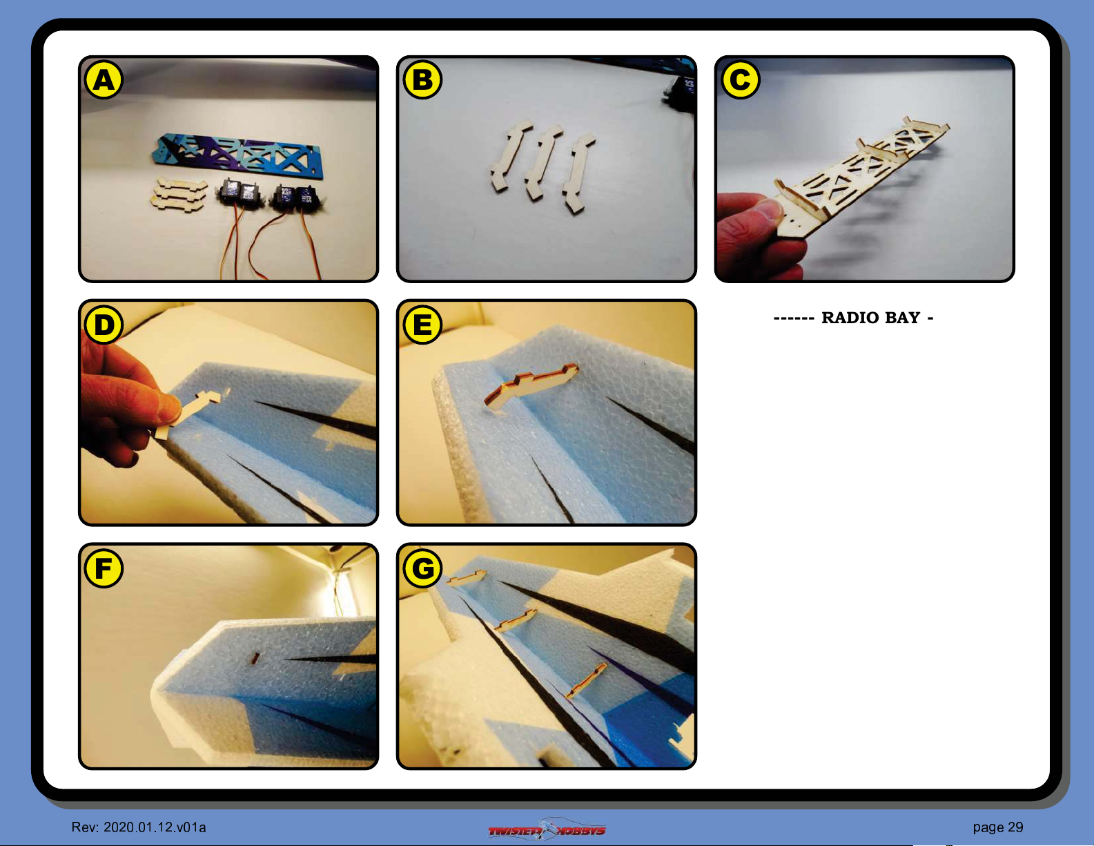
------ RADIO BAY ------
** NOTE **
THE FOLLOW SEVERAL PAGES ARE
THE PICTURES AND DESCRIPTIONS
THAT GO WITH ALL THE VERBIAGE
FROM THE PREVIOUS TWO PAGES
A Gather up the wood pieces shown
and servos that will be used
B Start by sanding the cross members
smooth
C Test #t the tray and cross members
together, do not glue at this time.
D Insert the front cross member into
the forward most pair of slots
E Angle it into the holes on both sides
of the fuselage
F Tabs should be "ush with the far side
of the fuselage, do not glue at this
time
G Repeat for the remaining two cross
members
♥
❥ ❦
♥♦♥
♦ ♣♦q♣q
♥
♦
❧
♠
q r
❧
♣
srt
✉
❦
Page 30
A B
C
D
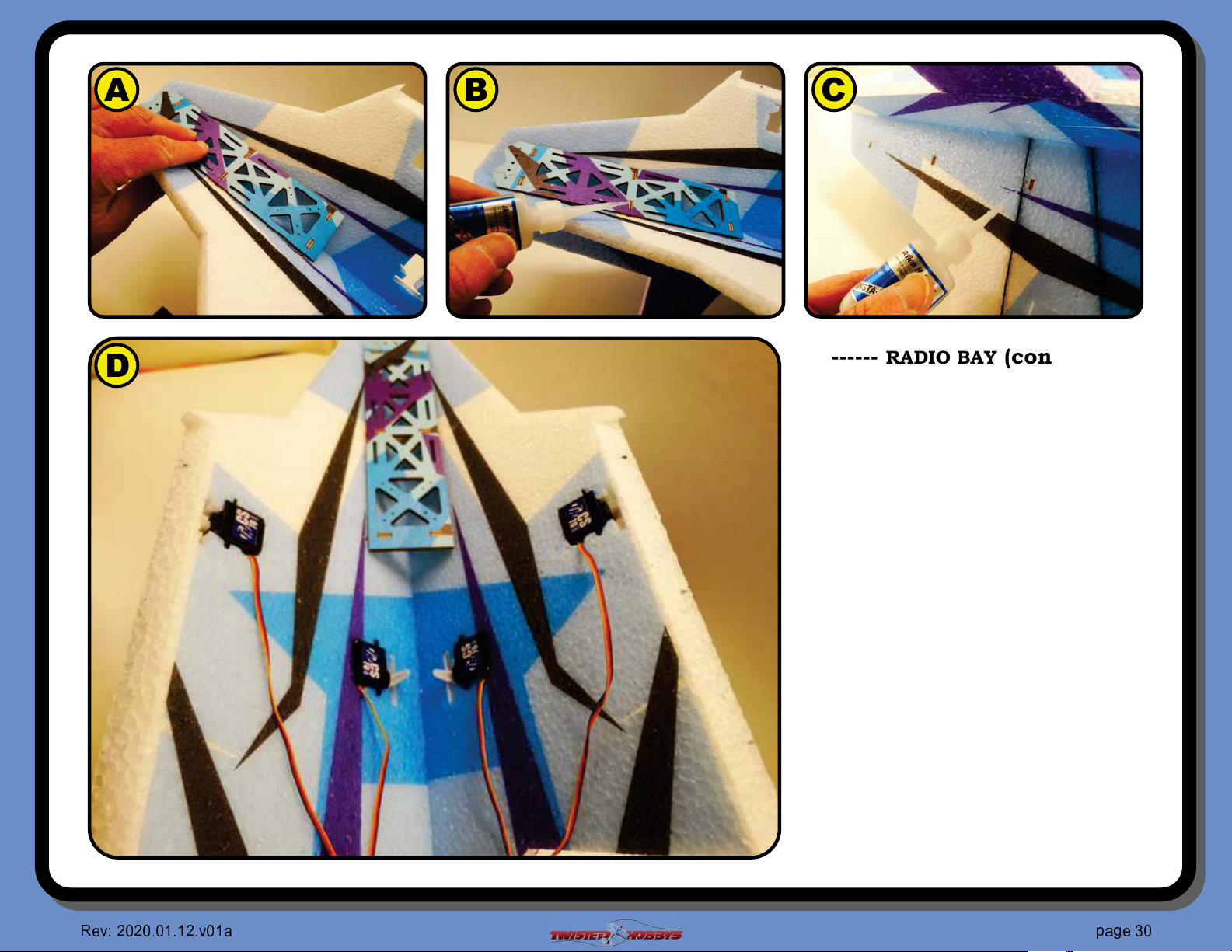
------ RADIO BAY (con’t) ------
A Fit the main tray piece to the cross
members, make sure all the tabs are
fully engaged
B Secure the main tray and cross
members together with a drop of thin
CA in the tabbed areas
C Secure the tray to the fuselage with
thin CA where the tabs stick thru the
foam. NOTE - you can leave these
tabs “unglued” if you want a
“removable” radio tray. It #ts tight
enough into the fuselage that glue is
not necessary.
D Install the four servos as shown.
Aileron servos near the wing saddle
will be "ush to the INSIDE, and their
arms will face outward. Tail servos
down in the “V” will be "ush to the
OUTSIDE and their arms are facing
inward. DO NOT GLUE THE SERVOS
IN AT THIS TIME.
✈
❥ ❦
♥♦♥
♦ ♣♦q♣q
♥
♦
❧
♠
q r
❧
♣
srt
♦
❦
Page 31
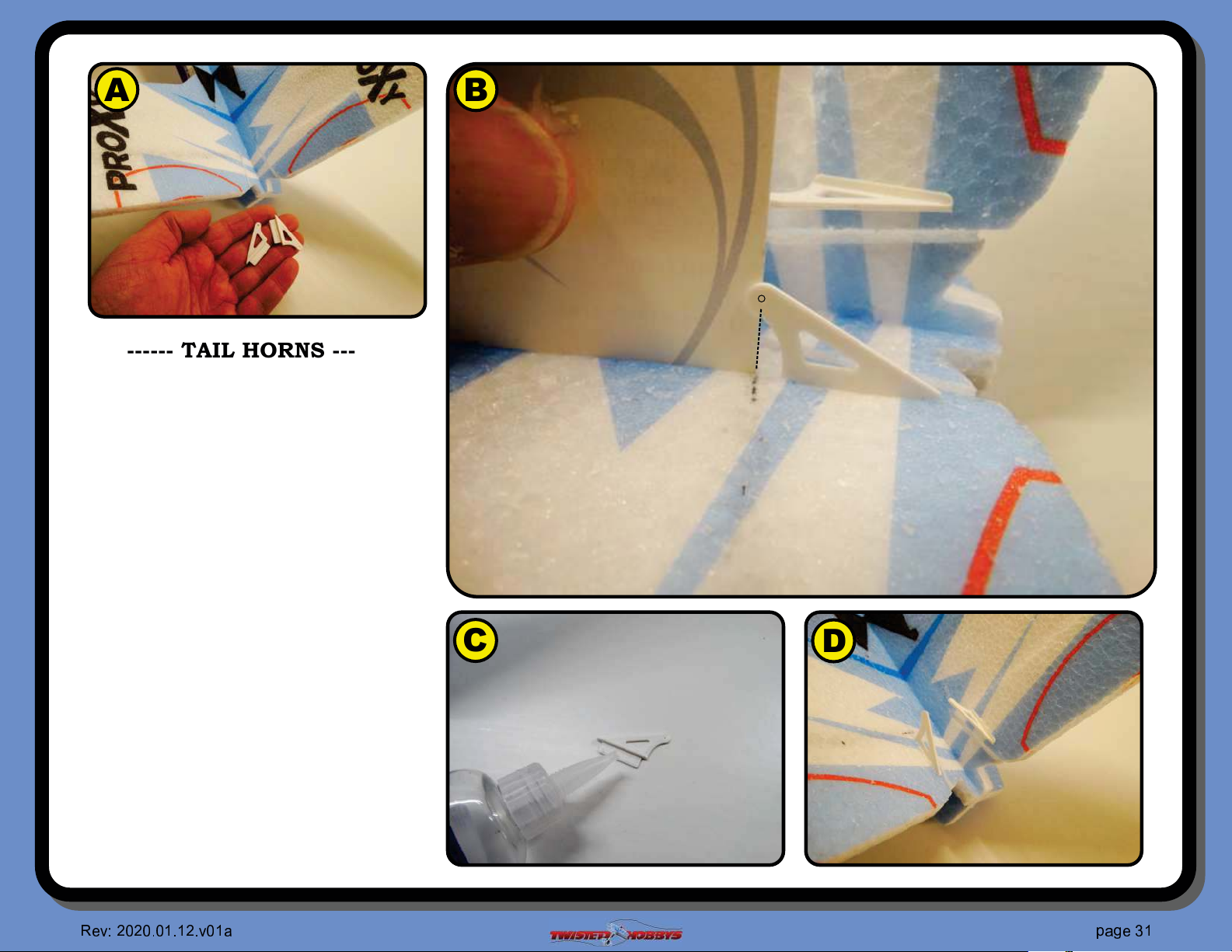
A B
------ TAIL HORNS ------
A Locate the remaining two control
horns. Note - All four control horns
are exactly the same, so it does not
matter which ones you use.
B Test #t them into the slots as shown,
making sure that the hole in the horn
is directly over the hinge line at the
neutral position
C When you are happy with the #t,
remove the horn and apply some glue
to both sides of the tab
D Re-Install into the slot, making sure
that the hole in the horn is still
positioned correctly in relation to the
hinge line as mentioned in the
previous step. Repeat for the other
tail control surface.
❥ ❦
♥♦♥
♦ ♣♦q♣q
♥
♦
❧
♠
q r
❧
♣
C
D
srt
✈
q
❦
Page 32
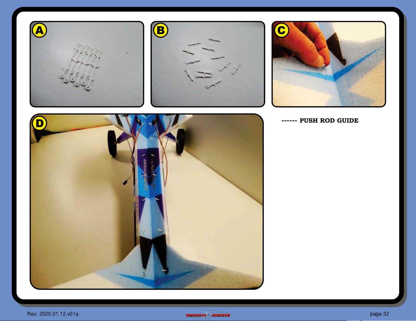
A B
C
D
------ PUSH ROD GUIDES ------
A Locate the tree of push rod guides
B Break them all apart. Note - they are
all the same length and size.
C Stick one each into the pre-cut holes
along the length of the fuselage boom.
Note that they will be located on the
TOP - INSIDE of the fuselage boom
D All guides installed. NO GLUE AT
THIS TIME
✈
❥ ❦
♥♦♥
♦ ♣♦q♣q
♥
♦
❧
♠
q r
❧
♣
srt
♥
❦
Page 33
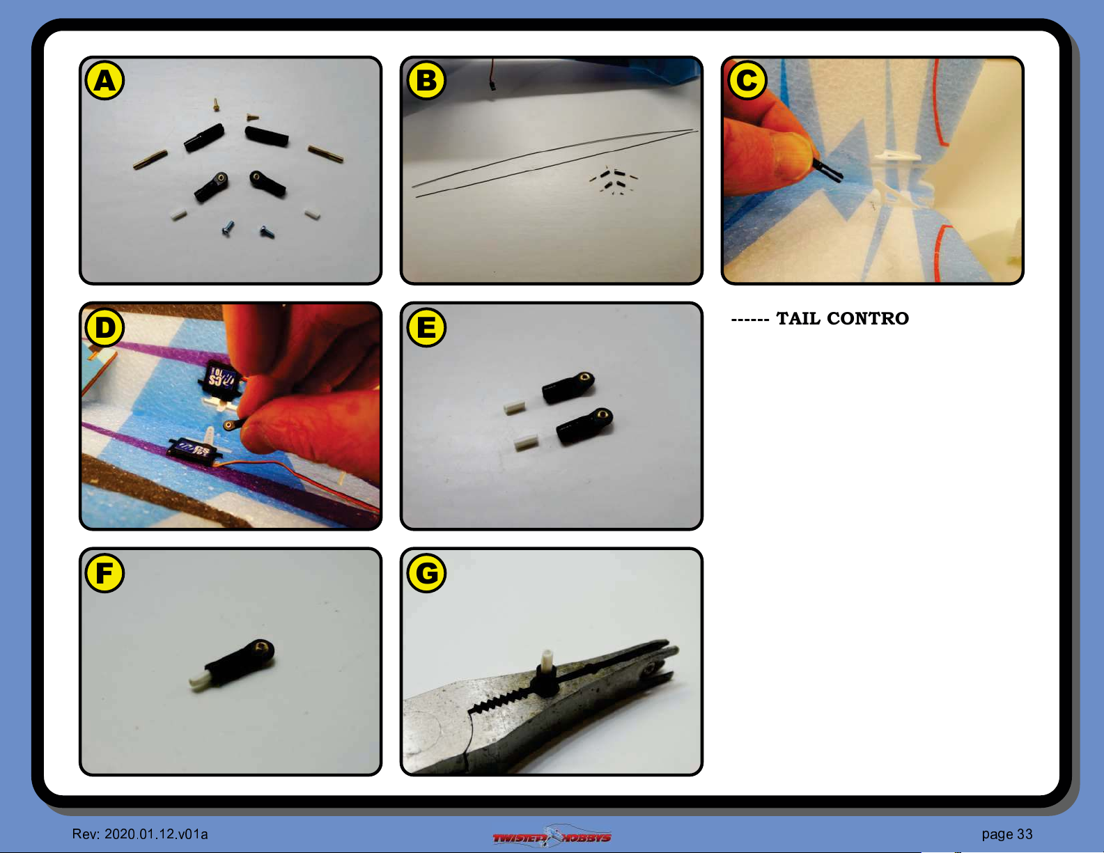
A B
C
D
E
F G
------ TAIL CONTROL RODS ------
PART I
A Gather up two clevises, two ball links,
two small brass pins, two of the
smaller threaded brass rod ends, two
tiny screws for the ball links and two
small white spacer tubes as all shown
in the picture
B Locate the two remaining .5x500mm
rods
C Note that this build will use the clevis
links on the control surface side of
the control rod, and....
D .... the ball link end will be used on
the servo side of the control rod
E Grab two ball links and the white
spacers
F Start the spacer into the end of the
ball link
G Hold the assembly gently with a pair
of needle nose or small pliers. Ball
link pliers are shown, if you have a
✈
❥ ❦
♥♦♥
♦ ♣♦q♣q
♥
♦
❧
♠
q r
❧
♣
srt
✈
❦
Page 34
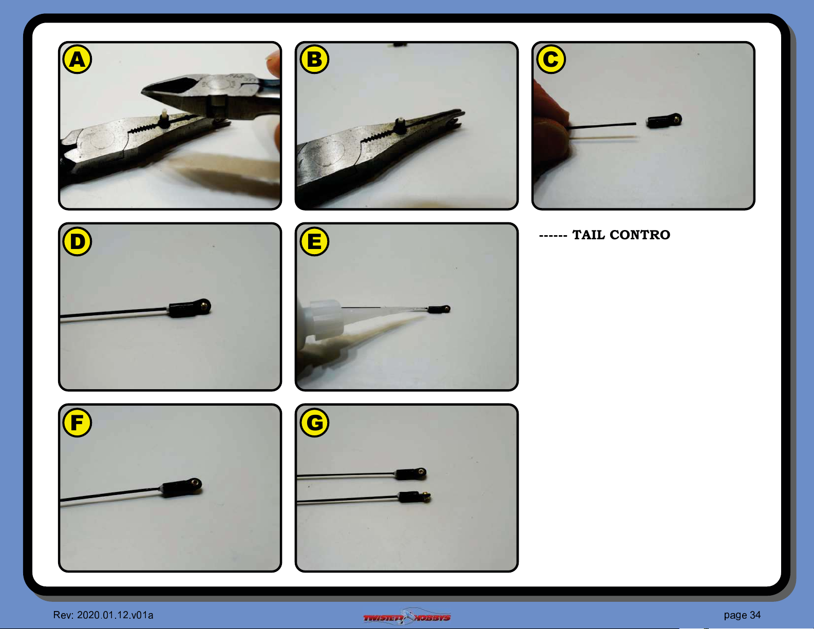
A B
C
D
E
F G
------ TAIL CONTROL RODS ------
PART I (con’t)
A Gently tap the spacer into the open
end of the Ball Link
B Note that there will be approx 1.5mm
of exposed length of the white spacer
as shown
C Test #t the control rod into the
spacer, dress up the end a little if
needed so that the rod will slide into
the spacer
D Slide it all the way in...
E ... and secure with some thin CA
F Let the CA sit for a minute then hit
with kicker
G Repeat for the other control rod
✈
❥ ❦
♥♦♥
♦ ♣♦q♣q
♥
♦
❧
♠
q r
❧
♣
srt
✇
❦
Page 35
A B
C
D
E
F G
------ TAIL CONTROL RODS ------
PART I (con’t)
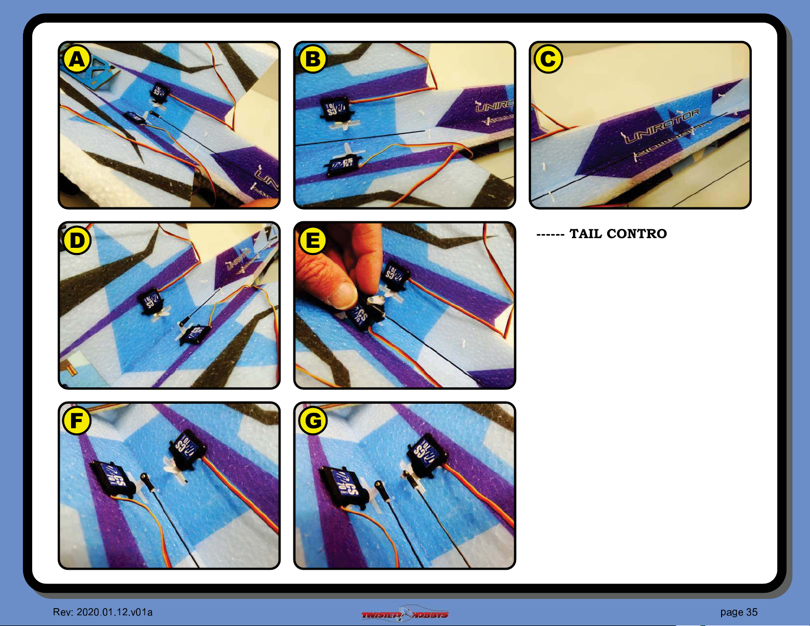
A As mentioned earlier, the ball link
end will attach to the servo arm
B Feed the free end of the control rod
thru the guides starting with the ones
closest to the servos
C Slide the rod all the way thru all the
guides
D The ball link should line up pretty
straight with the UNDER side of the
servo control horn
E Manipulate the servo so that you can
attach the ball link to the horn with
it’s mating tiny screw. Use a dab of
thread locker
F Put the servo back into it’s slot with
the body of the servo being "ush with
the OUTSIDE fuselage surface
G Repeat for the other control rod
✈
❥ ❦
♥♦♥
♦ ♣♦q♣q
♥
♦
❧
♠
q r
❧
♣
srt
①
❦
Page 36
A B
C
D
E
F G
------ TAIL CONTROL RODS ------
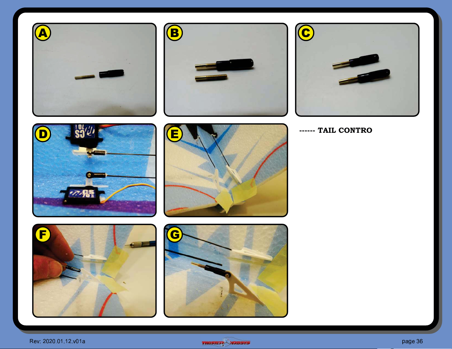
PART II
A Grab the small thread brass #tting
and the clevis as shown
B Thread the brass part in approx as
far as shown. This will give you a
little adjustment in both directions if
needed in the future
C Repeat for the other clevis
D ELECTRONICALLY CENTER THE
TWO TAIL SERVOS
E LOCK THE CONTROL SURFACES IN
THEIR NEUTRAL POSITION
F Grab one of the clevis assemblies just
made...
G ... and attach it to the control surface
horn with one of the little brass pins.
The hole in the horn may need to be
cleaned out a little. Make sure the
brass pin fully engages the clevis,
and snaps into it’s fully seated
position
✈
❥ ❦
♥♦♥
♦ ♣♦q♣q
♥
♦
❧
♠
q r
❧
♣
srt
②
❦
Page 37
A B
C
D
E
F G
------ TAIL CONTROL RODS ------
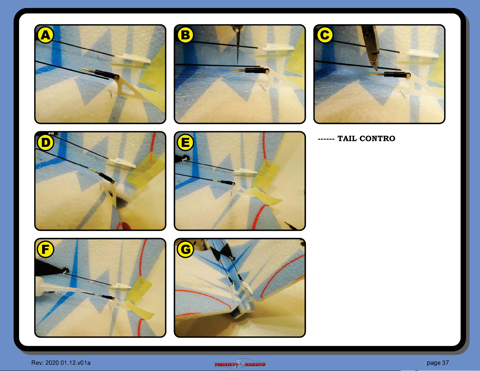
PART II (con’t)
A With the servo and control surface
both in centered/neutral positions,
there should be a little extra control
rod length.
B You will want to shorten the control
rod to a position that is just shy of
where the threaded part starts
C Clip to length with a pair of cutter
and dress up the end where it got
crushed from the cutters
D De"ect the control surface away from
it’s neutral position so that the end of
the rod can be slid into the brass
#tting
E Retrun the control surface to neutral,
if needed shorten up the rod a little
more
F With everything neutral, CA together
G Repeat for the other side
✈
❥ ❦
♥♦♥
♦ ♣♦q♣q
♥
♦
❧
♠
q r
❧
♣
srt
③
❦
Page 38
A
C
B
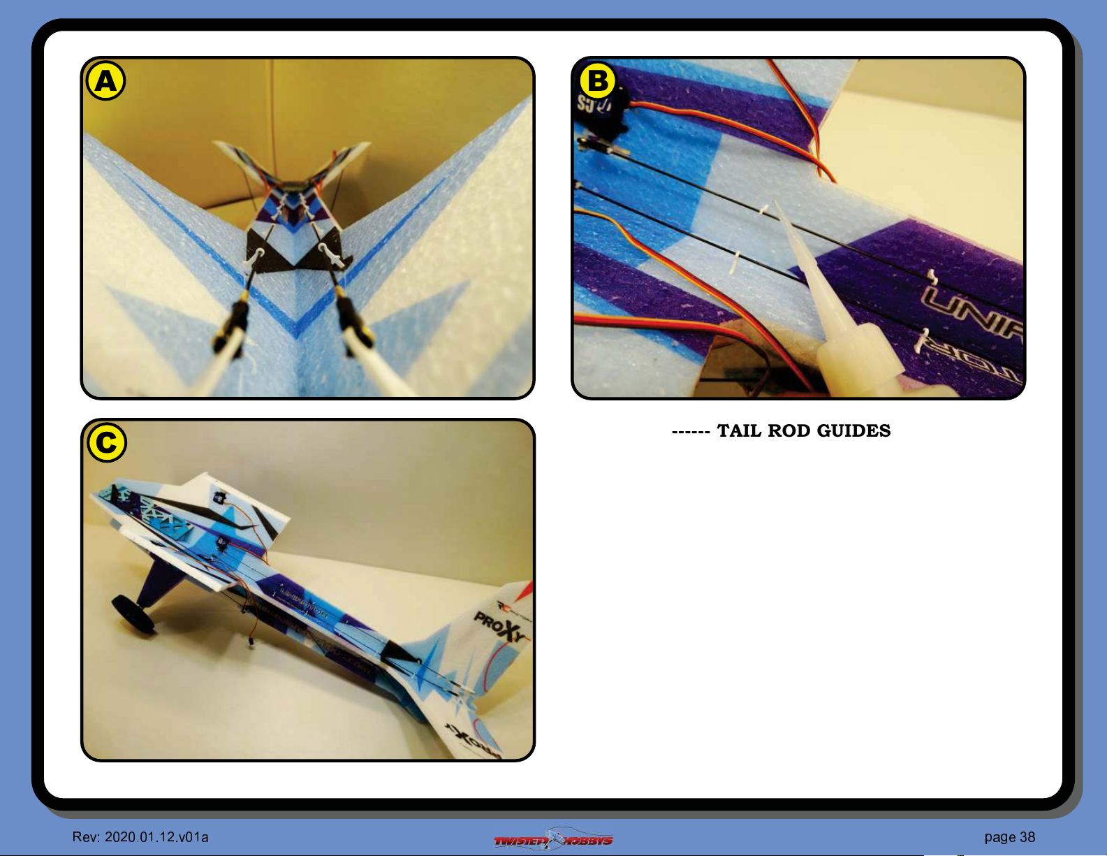
------ TAIL ROD GUIDES ------
A Eyeball down the length of the fuselage to make sure that
all the rod guides are straight and true and that all the
guides themselves are fully seated to their full depth.
B CA the bases of the guides to the surrounding foam, but
careful to avoid getting CA anywhere near the rod where it
feeds thru the rod guide
C If you have a servo tester you can double check the
centering and that there is no binding. If not this can be
done when a receiver is installed
✈
❥ ❦
♥♦♥
♦ ♣♦q♣q
♥
♦
❧
♠
q r
❧
♣
srt
④
❦
Page 39
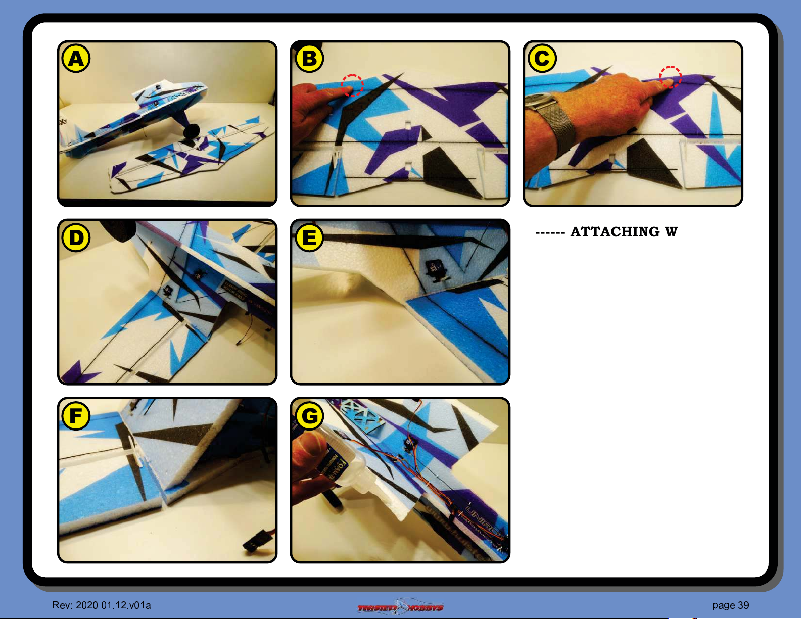
A B
C
D
E
F G
------ ATTACHING WING ------
A Attaching the wing is next, read thru the
steps on this and the next page to fully
understand the process before putting
glue to foam
B There are reference marks (cuts) near the
leading edge directly parallel with the
inboard end of the ailerons reliefs
C These two marks will be used as guides
when lining up the saddle area of the
fuselage with the wing
D Lay the wing on your work bench,
bottom side facing UP and test #t the
fuselage
E The wing should be all the way forward
until it is against the notch in the
fuselage saddle...
F ... and the front outside edge of the
saddle will line up with the reference
mark at the rear part of the saddle will
match up exactly to the aileron relief cut
G When you are happy with how everything
is lining up with the edges and reference
mark, apply a nice bead of FoamTac to
the saddle areas
✈
❥ ❦
♥♦♥
♦ ♣♦q♣q
♥
♦
❧
♠
q r
❧
♣
srt
✉
❦
Page 40
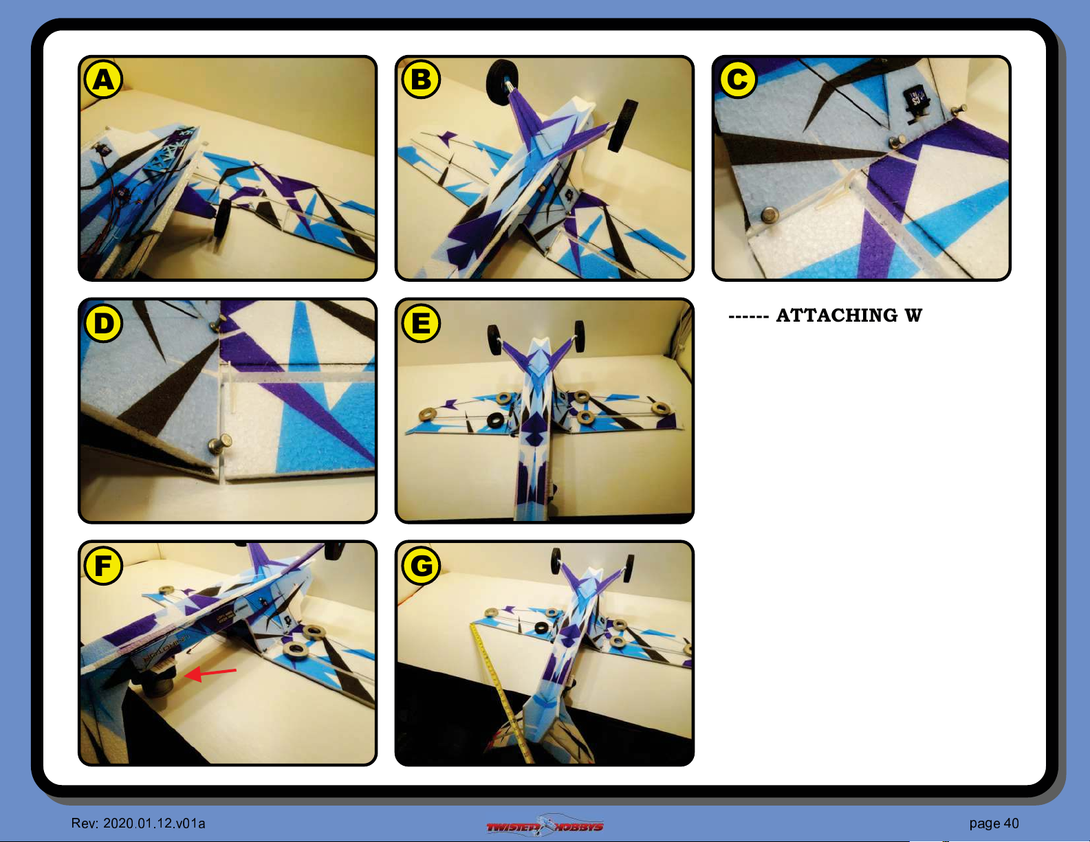
A B
C
D
E
F G
------ ATTACHING WING ------
(con’t)
A Wet glue method will be used to allow
for minor adjustments as needed
B Flip the fuselage over and line it up
with the forward notch and reference
marks as when test #t
C Long push pins can be used to hold
the two pieces in their exact position
D Make sure the edges line up perfectly
E Put some weights on the wings to
keep everything nice and "at
F Brace up the tail as shown to keep
the boom parallel
G Take some measurements from each
wing tip to a common point on the
tail to check for squareness of the
wing to the fuselage. Anything less
then 3/16” is #ne.
LET THIS DRY OVERNIGHT BEFORE
HANDLING AGAIN
✇
❥ ❦
♥♦♥
♦ ♣♦q♣q
♥
♦
❧
♠
q r
❧
♣
srt
♦
❦
Page 41
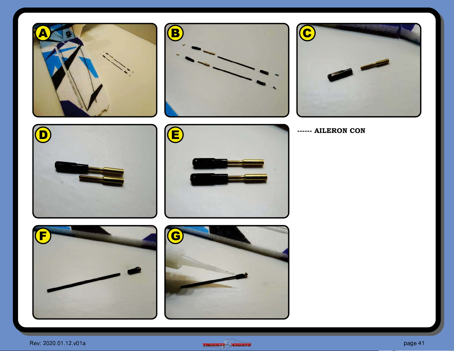
A B
D
E
C
------ AILERON CONTROL RODS ------
A Gather up the two 1.8x65mm rods
from the hardware packet along with
two larger brass ends two ball link
with screws and two clevises with
pins
B Detail view of the items need for this
step
F G
❥ ❦
♥♦♥
♦ ♣♦q♣q
♥
♦
❧
♠
q r
❧
♣
C The clevis end and brass part will be
the two screwed together
D Thread the brass part in approx as
far as shown
E Repeat for the other clevis, then set
these two aside for now
F Grab one of the ball links and test #t
it onto one end of the rod. Note that
you may have to dress up the end of
the rod a little for a nice smooth #t
G Once happy with the #t, slide the rod
all the way in and secure with thin
CA, make sure to keep glue out of the
area around the ball pivot
srt
❦
✇
q
Page 42
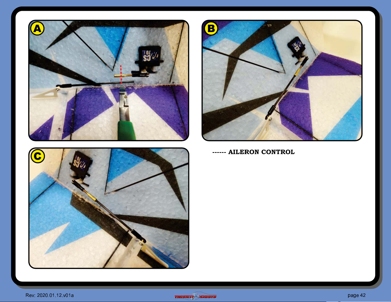
A
C
B
------ AILERON CONTROL RODS (con’t) ------
A Attach the ball link end to the aileron control horn, use a
little thread locker on the screw. Make sure the aileron is in
it’s neutral position and that the servo is electronically
center. Attach the clevis and pin to the outer most hole of
the servo control arm. Next trim the rod approx where
shown with the red dashed line
B Dress up the end of the rod as needed after cutting so that
it will slide into the brass #tting. Double check that both
the aileron and servo are centered and secure the rod and
brass #tting together with some thin CA. Be careful that
glue does not run into any unwanted areas
C Repeat for the other side
Note - In this build the ball link was put on the control
surface side. It could be the other way around, but with it
on the control surface side it will work a little smoother
✇
❥ ❦
♥♦♥
♦ ♣♦q♣q
♥
♦
❧
♠
q r
❧
♣
srt
♥
❦
Page 43
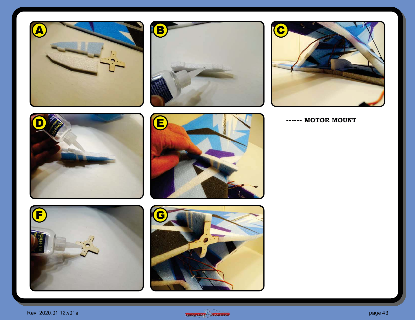
A B
C
D
E
F G
------ MOTOR MOUNT ------
A Gather up the pieces shown
B Apply some FoamTac to the all white
underside piece...
C ... and position as shown into it’s
respective slots
D Apply some FoamTac to the upper
color printed part...
E ... and position as shown into it’s
respective slots on the top side of the
wing
F Apply some FoamTac to one side of
the motor mount...
G ... and position as shown
Let these parts completely dry
before attaching the motor
✇
❥ ❦
♥♦♥
♦ ♣♦q♣q
♥
♦
❧
♠
q r
❧
♣
srt
✈
❦
Page 44
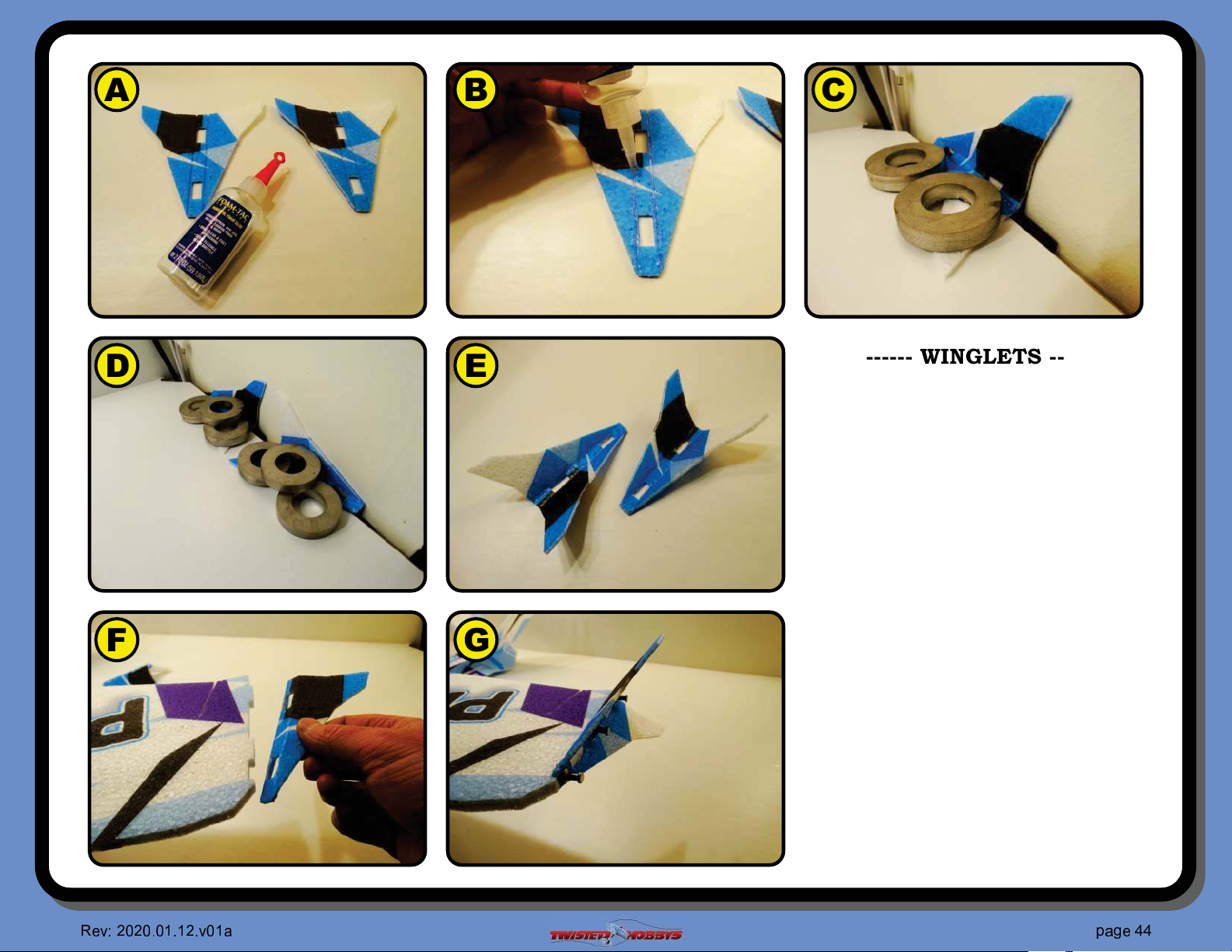
A B
C
D
E
F G
------ WINGLETS ------
A Gather up the two winglet pieces
B Apply some FoamTac into the two
BEVELED cut areas
C Position the winglet as shown up
against a vertical surface and secure
so that the glue can dry and hold the
winglet in this position
D Repeat for the other winglet
E Let the glue completely dry before
handling. They should hold their
shape very nicely
F Test #t on to the end of the wing, you
may need to clean out the slots in the
winglet where they are puckered a
little from being bent up at 45 degrees
G Once you are happy with the #t,
secure to the end of the wing with
some FoamTac and use some push
pins to hold in place until dry. Repeat
for the other side
✇
❥ ❦
♥♦♥
♦ ♣♦q♣q
♥
♦
❧
♠
q r
❧
♣
srt
✇
❦
Page 45
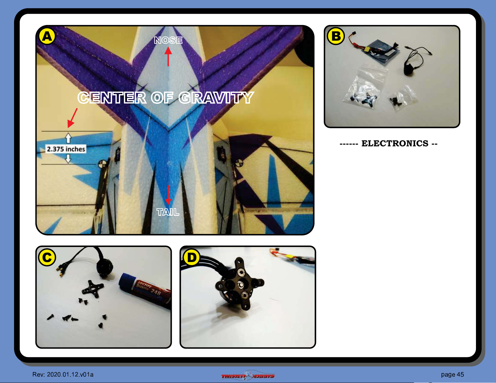
A B
NOSE
CENTER OF GRAVITY
A Start by locating the Center of Gravity
------ ELECTRONICS -----MOTOR
point for this airframe. Doing this
right now will help you in determining
where and how to locate all of the
onboard electronics
TAIL
C D
❥ ❦
♥♦♥
♦ ♣♦q♣q
♥
♦
❧
♠
q r
❧
♣
B Gather up the motor and mounting
hardware
C Attach the X mount to the back side
of the motor. Use thread locker
D If you are using the Twisted Hobbys’
motor and universal X mount, you
will attach the mount with two
screws to the holes that match up to
the motor
srt
❦
✇
①
Page 46
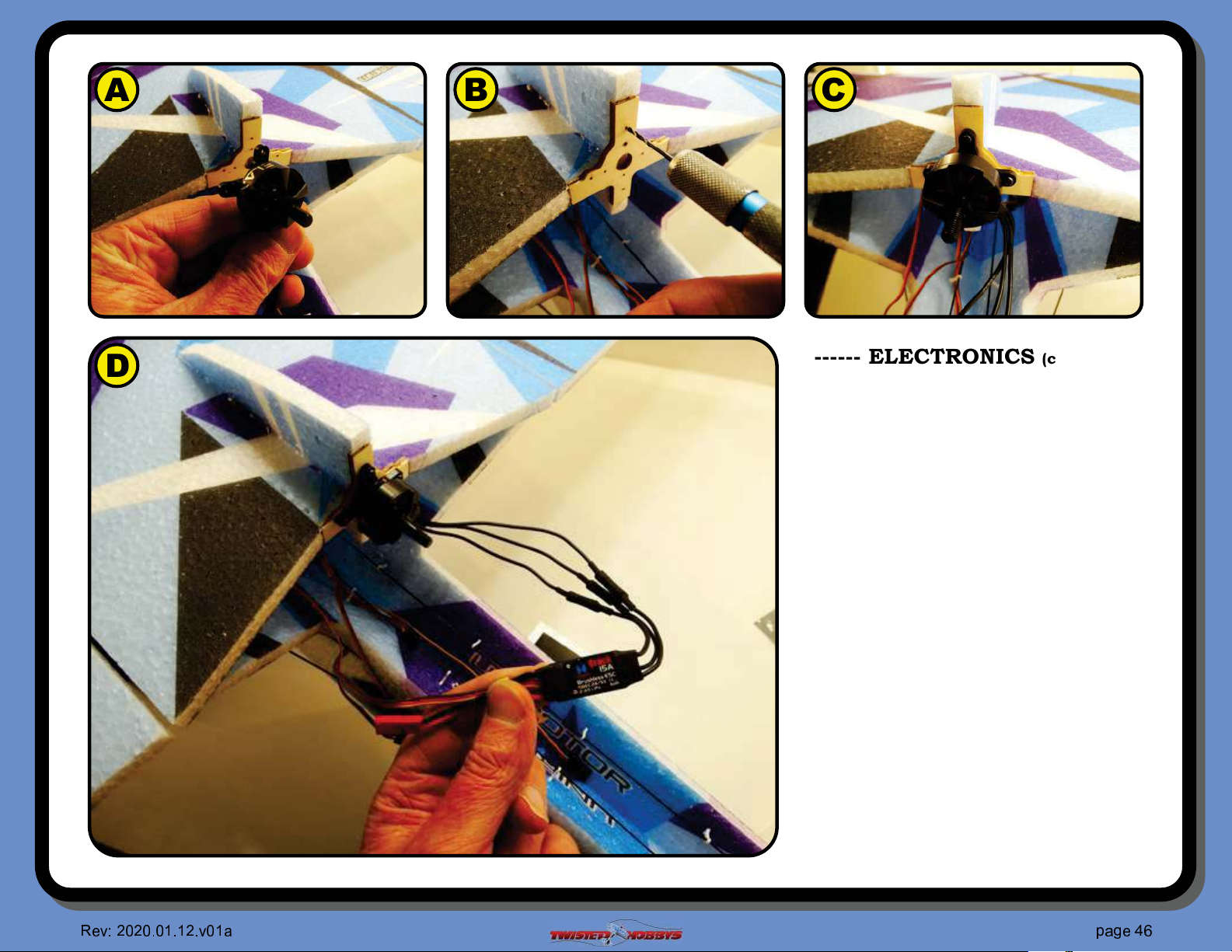
A B
C
D
------ ELECTRONICS (con’t) -----MOTOR
A The motor will mount to the wood
#rewall as shown, with the motor
wires pointing down, either to the left
or right side
B If you are using the Twisted Hobbys’
motor, enlarge the holes in the wood
mount with a 1/16” diameter drill,
this will keep the wood from splitting.
If you are using another motor and
mounting hardware, you may or may
not need to size the holes.
C Attach the motor
D Connect the ESC to the motor wires,
it does not matter right now how the
wires are connected, but you may
need to switch two of them around if
the motor spins in the wrong
direction once all the electronics are
installed
✇
❥ ❦
♥♦♥
♦ ♣♦q♣q
♥
♦
❧
♠
q r
❧
♣
srt
②
❦
Page 47
A B
C
D
E
F G
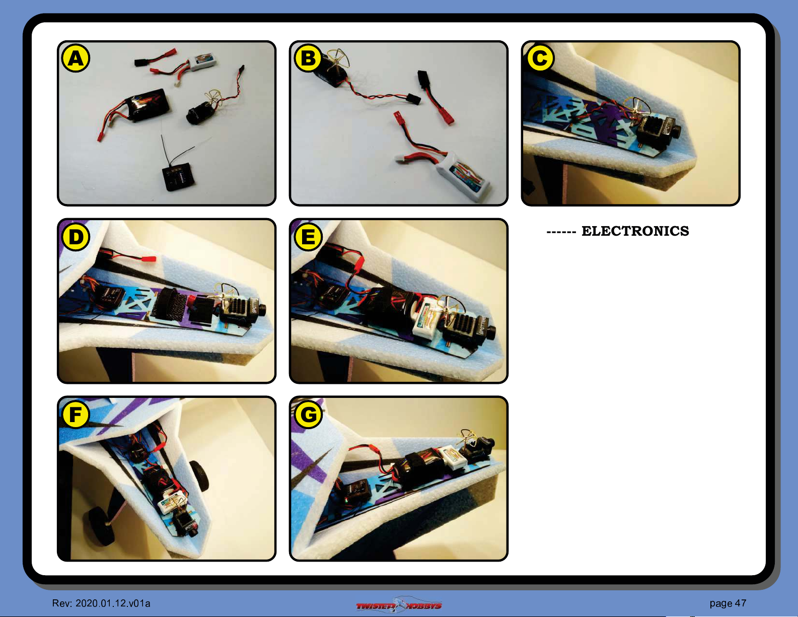
------ ELECTRONICS -----RX & FPV
There are many, many different options
available for setting this airframe up with
receivers, #ight controllers, FPV cameras
and HD recording potential. What is shown
here is just one possible solution. This
gear is simple and easy to setup and will
have you #ying FPV without a bunch of
programing or wiring.
A Admiral RX with Stability and Twisted
Hobbys’ Spotter CAM/VTX
B Spotter CAM/VTX will use a
dedicated battery for cleanest signal
C Spotter Mounted in the nose
D Admiral RX mounting position
E Flight Pack Battery position
F Tuck the wires away for clean setup
G Ready to go... !
✇
❥ ❦
♥♦♥
♦ ♣♦q♣q
♥
♦
❧
♠
q r
❧
♣
srt
③
❦
Page 48
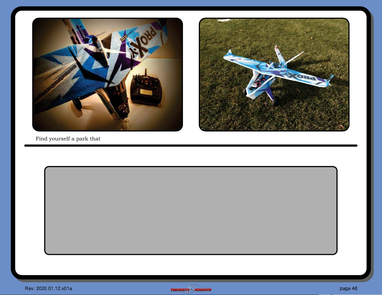
Find yourself a park that is out of the way and full of spaced out trees or other obstacles, strap on the goggles and go..!!
This completes the build, it’s design and construction should give you many
hours of #ying enjoyment. This airplane will serve you well, whether you are
new to FPV #ying or are a seasoned veteran.
Please visit www.TwistedHobbys.com for other accessories and aircraft.
There are several online resources and forums for this model as well. It is
suggested that you visit the RC Groups Thread for this model for additional
information, it is a great resource for questions and insight to this aircraft.
✇
❥ ❦
♥♦♥
♦ ♣♦q♣q
♥
♦
❧
♠
q r
❧
♣
srt
④
❦
Page 49
center of gravity and control throws
NOSE
CENTER OF GRAVITY
TAIL
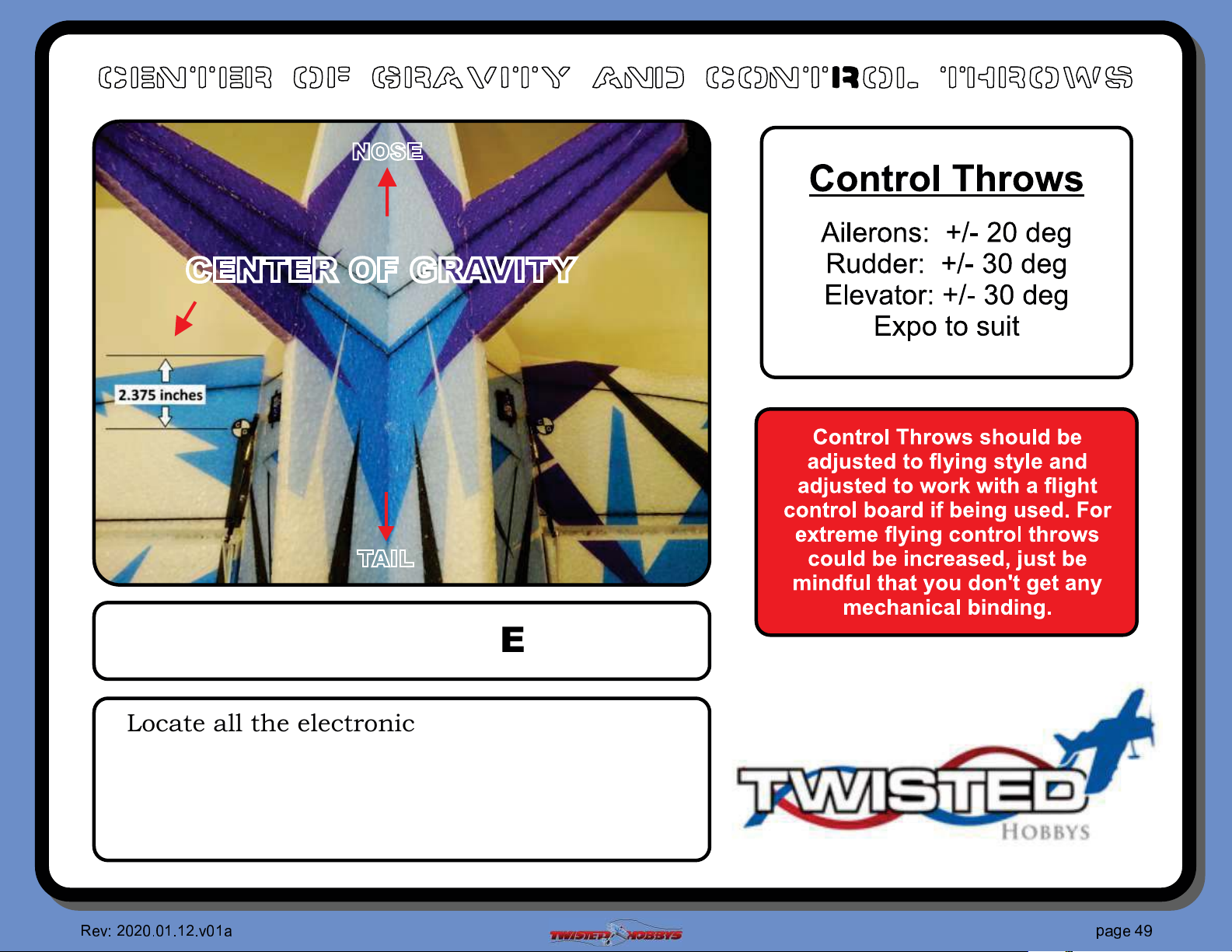
C.G. - 2.375” from LE of wing
Locate all the electronics to achieve indicated
CG point. Use Velcro for initial "ights for
battery mounting and experiment with it’s
position until you have determined the best
spot for your "ying style.
❥ ❦
♥♦♥
♦ ♣♦q♣q
♥
♦
❧
♠
q r
❧
♣
srt
✇
✉
❦
Page 50
pre-flight & testing
Pre ght!Checks Pre ght!Checks
Storage
Be safe and enjoy, thank you again for purchasing a Twisted Hobbys’ Product!
❥ ❦
♥♦♥
♦ ♣♦q♣q
♥
♦
❧
♠
q r
❧
♣
srt
①
♦
❦
Page 51

TIPS AND TRICKS
A good building surface is —drop ceiling“ panel from a local hardware store on a nice flat board
Use parchment paper between the areas being glued and your wo rk surface
Heavy flat o bjects (like books, batteries, etc.) could be used t o hold everything flat
When resetting your radio, start with all the ATV‘s or throw volumes at 100%.
Make sure you have set the direction of the servos correctly before attempting to trim for zero position.
If possible t ry the servo horns in different locatio ns to determine which position will require the least amount of
sub trim.
Installing the servo horns in their fi nal location and attaching quick links to the servos may make servo
installation much easier later.
On the Orange Rx, the negative pin is the one closest to the flat side of the circuit board.
Keep a good suppl y of sharp knife blades handy when building a foamie airplane.
Use low temp hot glue for gluing electronics, this will allow for easy removal later if necessary. The lo w temp hot
glue can be “released” by paint ing” the glue bead wit h an alcohol soaked cotton swab a couple times.
A business card with the corners clipped off can be used as a small square.
Allowing the Welders glue to set for five minutes before assembly will shorten th e tack up time, just be sure if
do ing it this way that you get the parts into position quickly, as the glue will start to bond o n contact . Any join ts
that you feel are going to require adjustment, it is best to assembly the pieces while the glue is wet. The Green
(high tack) masking tape works the best when used to clamp things toget her on an EPP foam airplane.
When gluing the rudder to the fuselage, stick pins could be used to ho ld in position if wanting to handle the
airframe before it is completely dry
A rotary tool with a cutting wheel could be used to produce grooves in fiber glass parts instead of coarse sand
paper. Use a hatch pattern. This creates more bonding area for the glue.
①
❥ ❦
♥♦♥
♦ ♣♦q♣q
♥
♦
❧
♠
q r
❧
♣
srt
q
❦
Page 52
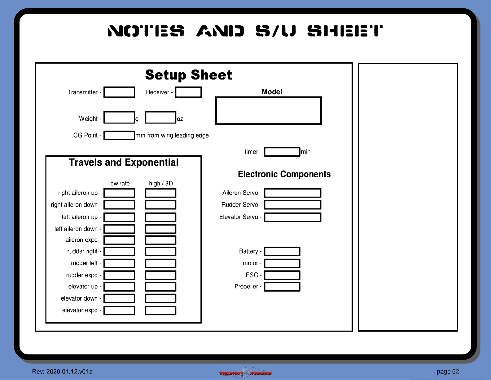
notes and s/u Sheet
①
❥ ❦
♥♦♥
♦ ♣♦q♣q
♥
♦
❧
♠
q r
❧
♣
srt
♥
❦
 Loading...