

Page 1

Rev: 2015.08.16.v01a
page 1
USA Distributor
Twisted Hobbys
www.twistedhobbys.com
MOTOR: 2x 19-26g/1450-1750 Outrunner
ESC: 2x 10-12 amp
SERVOS: 4x 5-7g
PROP: 2x 7x3.5dd or 7x6sf
BATTERY: 3s / 650-850mAh
RADIO: min. 4 channel
WINGSPAN: 39”
LENGTH: 39”
AUW: 390 to 420 grams
PPUUD
D
D
DLLEE
SSTTAAR
R
Page 2
Rev: 2015.08.16.v01a
page 2
SAFETY NOTES
Before assembling and flying this model, read carefully any instructions and warnings of other
manufacturers for all the products you installed or used on your model, especially radio
equipment and power source.
Check thoroughly before every flight that the airplanes’ components are in good shape and
functioning properly. If you find a fault do not fly the model until you have corrected the
problem.
Radio interference caused by unknown sources can occur at any time without notice. In such a
case, your model will be uncontrollable and completely unpredictable. Make sure to perform a
range check before every flight. If you detect a control problem or interference during a flight,
immediately land the model to prevent a potential accident.
Youngsters should only be allowed to assemble and fly these models under the instruction and
supervision of an experienced adult.
Do not operate this model in a confined area.
Do not stand in line with, or in front of a spinning propeller and never touch it with any object.
IMPORTANT: PRIOR TO ANY ASSEMBLY
Please Note: after removing kit from shipping box, lay each piece flat on a
hard surface, this will allow the airframe to straighten out if lightly bent
from shipping. Do not worry since EPP is very pliable and can be bent back
if out of shape.
Page 3
Rev: 2015.08.16.v01a
page 3
TWISTED HOBBYS
Website: www.twistedhobbys.com – email: sales@twistedhobbys.com
Thank you for your purchasing a Twisted Hobbys‘ model. Please read through the entire manual before beginning to
build this model. If you have any questions please contact us at the above indicated email address.
WARNING INFORMATION
This R/C Aircraft is not a toy! Read and understand the entire manual before assembly. If misused, it c an cause serious bodily harm and
property damage. Fly only in open areas, and AMA (Academy of Model Aeronautics) approve d flying sites. Do not over look the warnings
and instructions enclosed or those provided by other manufactures’ products. If you are not an experienced pilot and airplane modeler you
must use the help of an experienced pilot or an authorized flight instructor for the building and flying of this model aircraft.
These instructions are suggestions only on how to assemble this model. There are other ways and methods to d o so. Twisted Hobbys has
no c ontrol over the final assembly, the materials and accessories used when assembling this kit, or the m anner in which the assembled
model, installed radio gear and electronic p arts are used and maintained. Thus, no liability is assumed or accepted for any d amage
resulting from the use of th e assemb led model aircraft or from this instruction manual including but not limited to direct, indirect,
incidental, special, and consequential damages. By the act of using this user-assembled product, the user accepts all resulting liability. In
no event shall Twisted Hobbys’ liability exceed the original purchase price of the kit.
SHIPPING DAMAGE
Twisted Hobbys checks each plane before shipping to ensure that each kit is in fine condition. We have no bearing on the condition of any
component parts damaged by use, modification, or assembly of the mod el. Inspect the components of this kit upon receipt. If you find any
parts damaged or missing, contact Twis ted Hobbys immediately. We will not accept the return or replacement of parts on which assembly
work has already begun. Twis ted Hobbys reserves the right to change this warranty at anytime without notice.
OUR MISSION
To provide the best products and service to our customers at the lowest prices pos sible. We take great pride in
our company, our commitment to customer service and in the products we sell. Our online store is designed
to provide you with a safe and secure environment to browse our product catalog.
Thank you for shopping with Twisted Hobbys!
Page 4
Rev: 2015.08.16.v01a
page 4
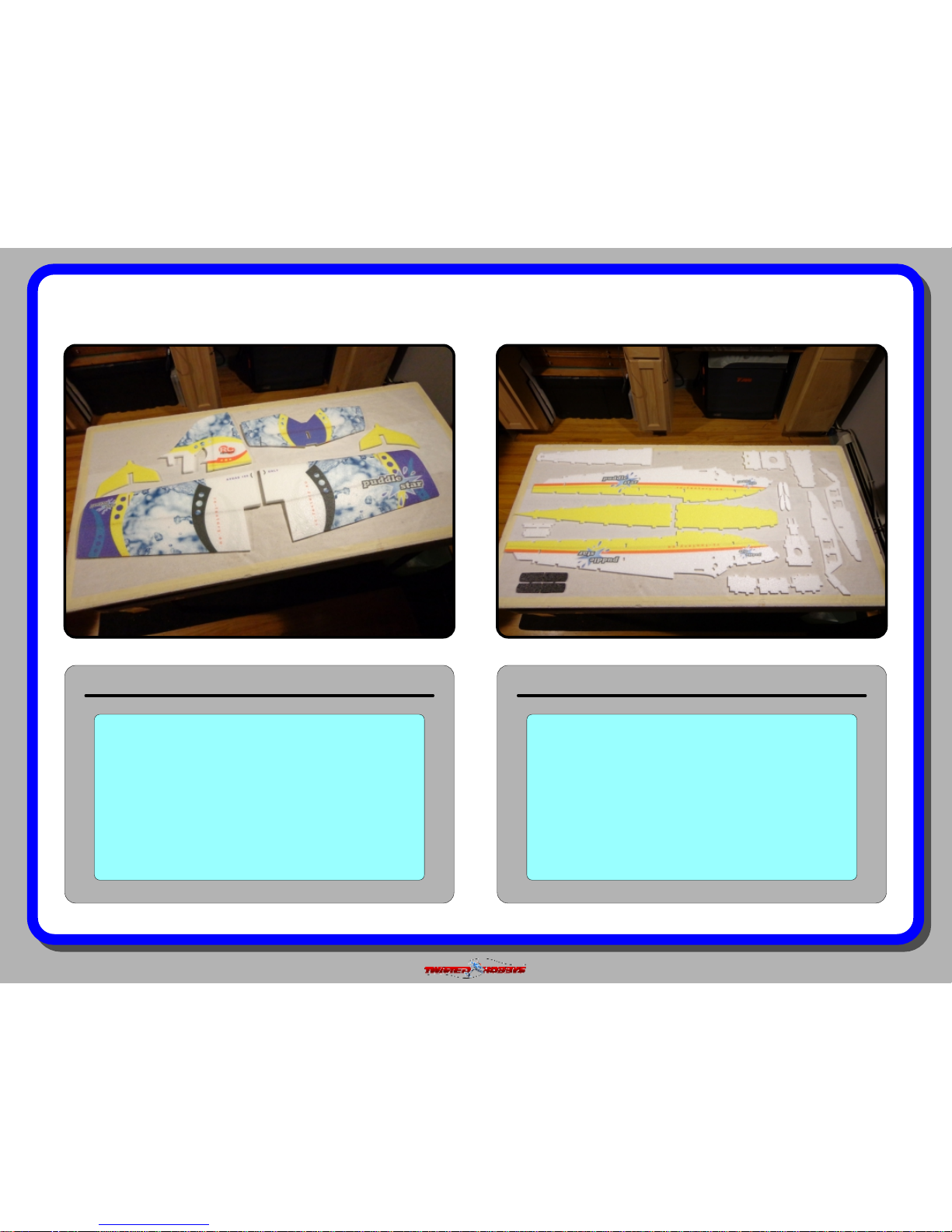
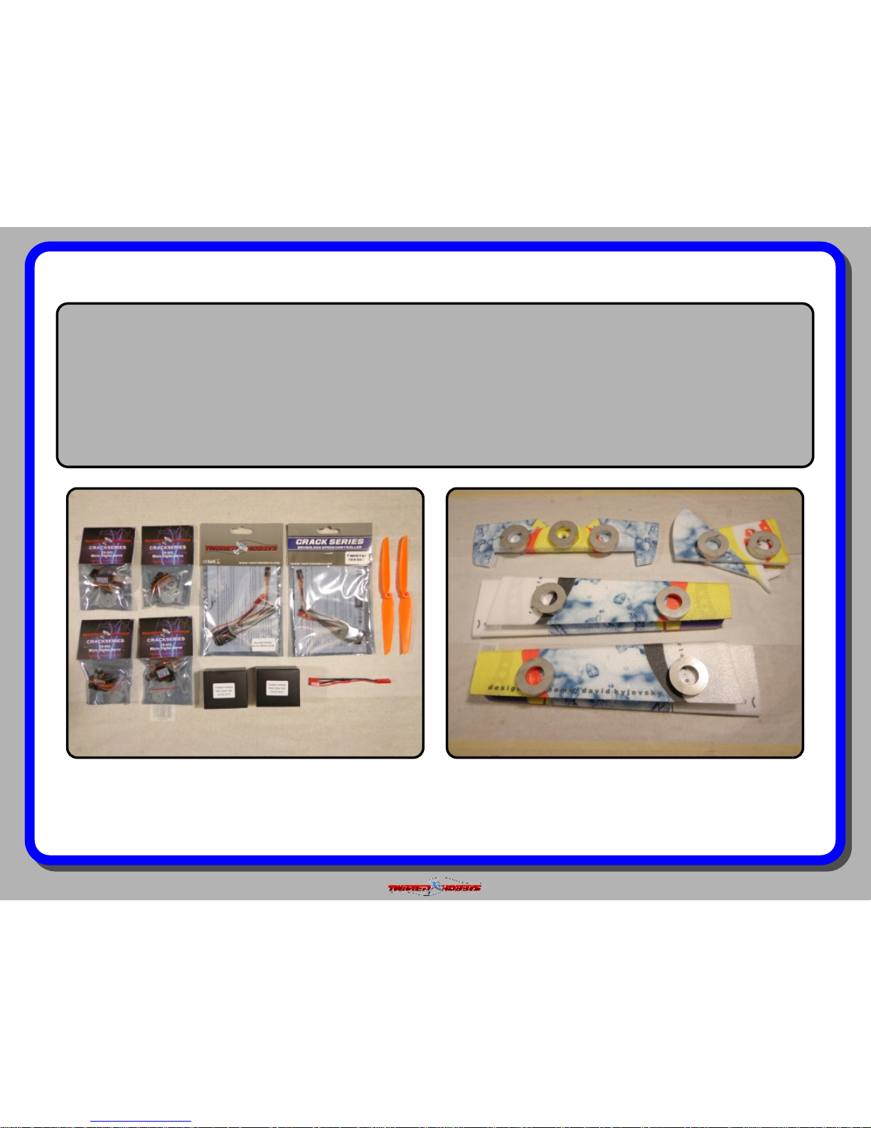
kit contents
Fuselage Parts
Double check that you have all the
above pictured items. Note - Some
kits might have slight deviations from
the above pictured items.
Wings, SFG’s and Tail Surfaces
Double check that you have all the
above pictured items. Note - Some
kits might have slight deviations from
the above pictured items.
Page 5
Rev: 2015.08.16.v01a
page 5
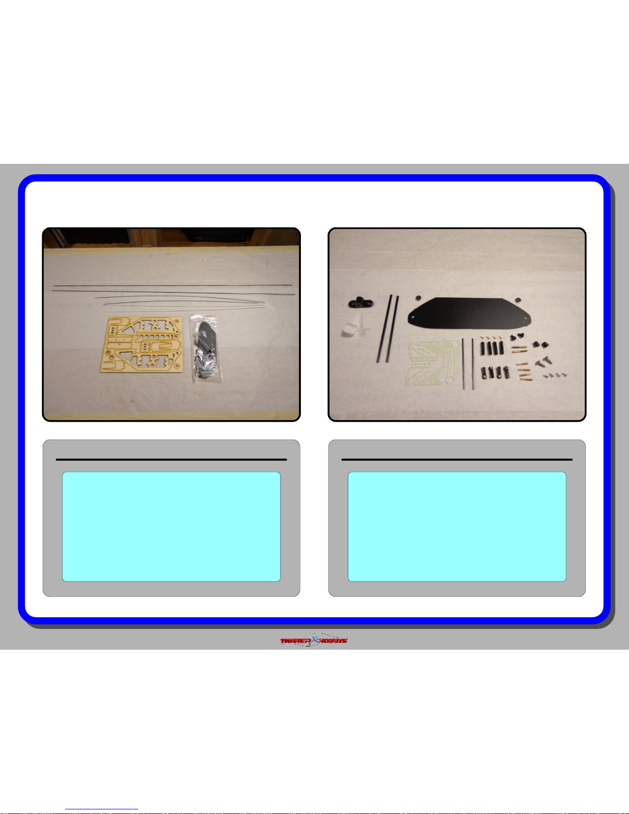
kit contents (cont.)
Hardware Kit Detail
Double check that you have all the
above pictured items. Note - Some
kits might have slight deviations from
the above pictured items.
Plywood and Hardware Kits
Double check that you have all the
above pictured items. The Hardware
kit items are detailed to the right.
Note - Some kits might have slight
deviations from the above pictured
items.
Page 6
Rev: 2015.08.16.v01a
page 6
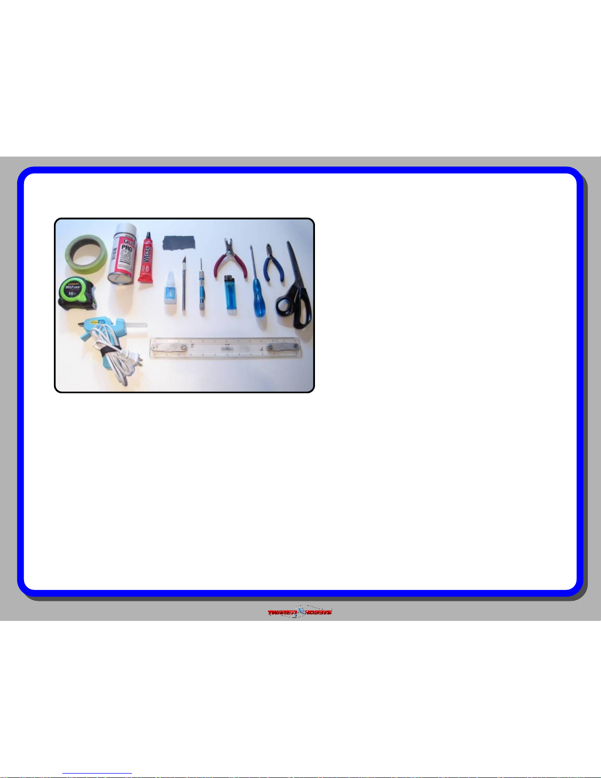
TOOL AND ADHESIVES NEEDED
Tools shown and listed are suggestions only.
Depending on your building technique you may not
need everything indicated – and/or – you may find that
other tools available to yourself may be of benefit to
your Build.
It is also recommended that you have a flat building
surface, one that will accept stick pins and push pins.
An Acrostic Ceiling panel from your local hardware
store fits this bill nicely, and will lay flat on your work
table. Over size / long push pins are available at your
local craft store. These two items are by no means
required, but will aid in the building process, and can
be used for future projects
Lighter
Small Drill Bits
Tape Measure and Ruler
Black Sewing Thread
Welders Glue
Hobby Knife w/new Blade
Needle Nose Pliers
Wire Cutters
Low Temp Hot Glue Gun
Course Sand Paper
Scissors
Small Phillips Screw Driver
Thin and Medium CA
CA Applicator Tips
Activator
Page 7
Rev: 2015.08.16.v01a
page 7
the build
CONSTRUCTION METHODS:
Building surface should be at least 2ft x 4ft and at. Weights or some small heavy objects will be handy for holding things in place
during the time glue is setting.
Welders glue is used for FOAM TO FOAM joints. Thin and Medium CA are used on the PLASTIC TO FOAM and CARBON TO FOAM
joints. When using the Welders glue for a butt joint, apply a thin lm to each surface, allow to sit for approx ve minutes and
then assemble. Note that this method will create a nearly instant bond, so locate carefully when bringing the two pieces together. If
alignment is necessary or a slip joint, do not allow the glue to tack up, simple apply and join immediately, you will have several
minutes to locate the two parts before the glue sets up. In most cases the parts being glued can be handled with care in 30 minutes,
full cure is approx 24 hours.
The above picture items will be needed to nish the model.
A power combo (Twisted Hobbys’ Combo pictured above), a
3s/650-850mAh battery and a fresh tube of Welders. Note -
the Battery and Welders are NOT part of the power combo.
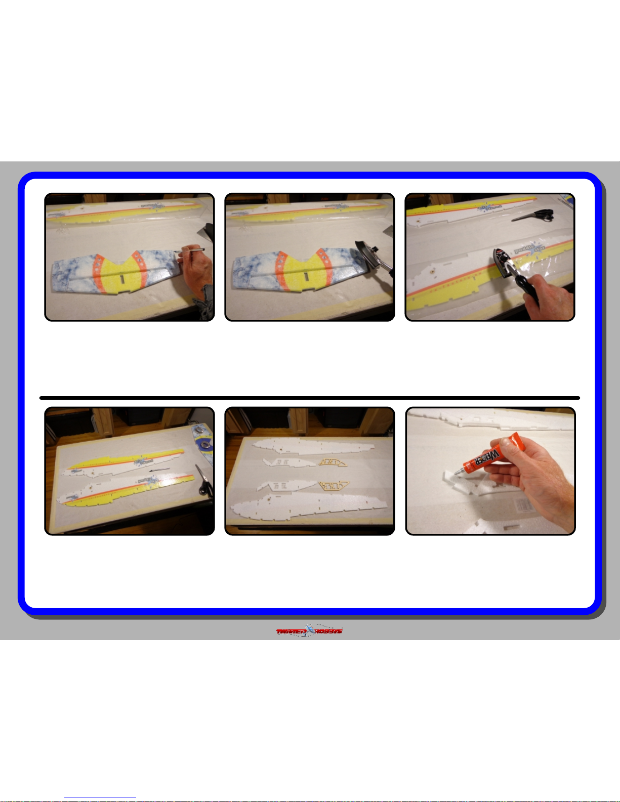
Start the build by locating the two wing halves, the elevator
and the rudder. Fold back as shown and weigh them down
for about an hour. This will loosen up the hinge line and
allow the surfaces to move much more freely. The wing
hinge will be stiff... work it slowly so it doesn’t tear
Page 8
Rev: 2015.08.16.v01a
page 8
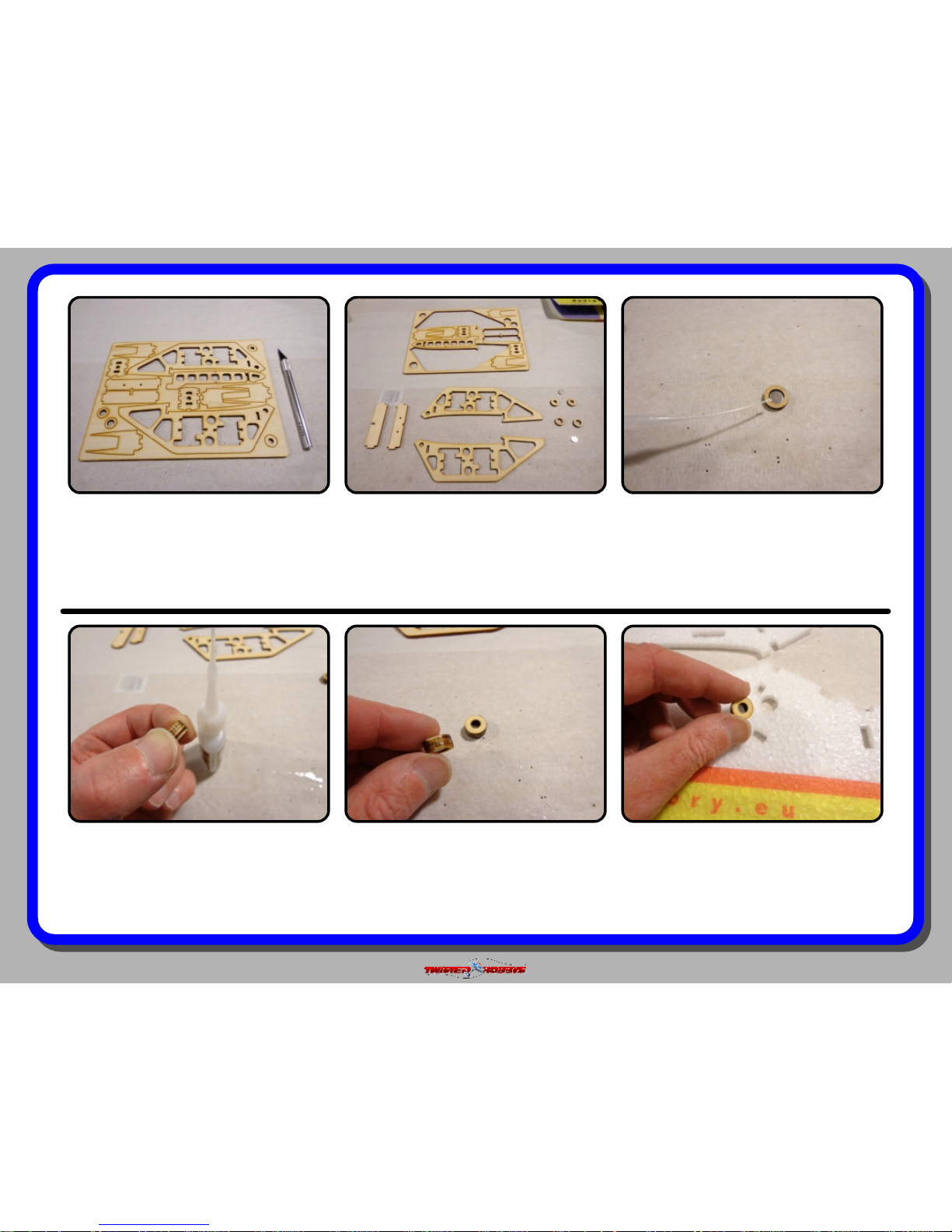
Locate the wood kit and mount a fresh
blade into you hobby knife.
Cut out the Fuselage Doublers, the
Wing Mount Cross Members and the
little round Magnet Holders. Also locate
the magnets from the hardware bag.
Press a magnet into the Wood Holder
(the one with the larger hole). Make
ush with one side. Glue with Med. CA
and Kicker.
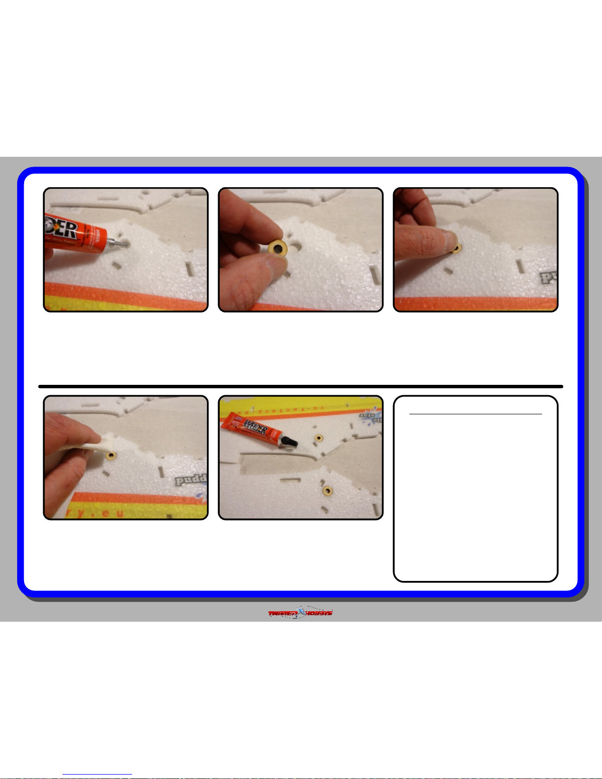
The magnet assembly installs with the
smaller hole to the OUTSIDE of the
fuselage.
Repeat for the second side.
With thin CA, attach the round piece
with the smaller hole to the side you
made the magnet ush with.
Page 9
Rev: 2015.08.16.v01a
page 9
Coat the inside of the magnet hole in
the fuselage with a little Welders.
Install as shown, again remembering
that the smaller hole is facing out.
Press into the hole... should be ush to
both the inside and outside of the foam
fuselage piece.
Repeat for the other side.
Wipe away any extra Welders
LEVEL OF WATER PROOFING
At this point in the build you
should decide what level of water
proong you will do. If you plan to
spend a fair amount of time ying
off water, a more robust
“waterproong” (waterbug) build
would be in order. The occasional
water use... 2 or 3 times a season,
the standard (grasshopper) build
would be sufcient. If you never
intend to y off the water, omit all
the build steps that install lm or
require water proong. The only
thing you will want to do is coat the
bottom of the fuselage with some
clear duct tape or similar tape.
Page 10

Rev: 2015.08.16.v01a
page 10
Waterbug Build Only - Locate the
pieces shown, these are the items that
will get the laminate. Skip all the steps
labeled “Waterbug” if only occasionally
ying off the water.
Waterbug Build Only - cut a piece of
1.5mil heat laminate material that will
cover the bottom of the elevator
Waterbug Build Only - The laminate
material will shrink like monokote and
will bow the foam if not careful. Only
the bottom of the elevator needs it.
Start in the middle and work outward
Waterbug Build Only - ON A TEST
PIECE OF FOAM, IRON ON A SMALL
PIECE OF THE LAMINATE (DULL SIDE
IS THE STICKY SIDE) AND
EXPERIMENT WITH TEMPERTURES
Waterbug Build Only - Cut one piece
each for the fuselage sides
LAMINATING BUILD TIPS
There are many different thickness
and brands of laminate material
out there. You should use a
laminate that has a low heat
activated glue. As an extra step to
insure a robust bond of the
laminate to the foam, 3M 77
Contact Spray glue can be used to
“dust” the area in which you will
apply the laminate to. Note, it does
not take a lot, a quick single pass
at 10 to 12 inches is plenty, more
is not better in this case. Also, it is
advised to TEST your procedure
and iron tempatures on a scrap
piece of foam and not your model.
Page 11
Rev: 2015.08.16.v01a
page 11
Waterbug Build Only - Once you are
happy with the lm application, Trim
around the perimeter of the elevator,
and cut away the area for the hinge
bevel. A fresh blade should be used.
Waterbug Build Only - Once everything
is trimmed up, seal all the edges.
Waterbug Build Only - Repeat the
process with the outside surface of the
two fuselage pieces. Again, starting
from the center and SLOWLY working
towards the tail and nose
Lay down a small bead of Welders all
around the foam doubler.
Locate the foam and plywood fuselage
doublers as pictured above.
Waterbug Build Only - When complete,
trim as with the elevator. NOTE - Do
not cut the lm away from the notches.
Leaving them will provide covering for
the mating tabs later in the build
Page 12
Rev: 2015.08.16.v01a
page 12
Spread the glue out evenly so that it
coats the whole surface. Use an old
business card or something as a
spreader.
Attach to the inside of the fueslage.
NOTE - it is VERY important to line up
all the notches and edges of the two
pieces.
The foam doubler will curl up a little as
the Welders dries, so secure everything
at with some weight for an hour or
two.
Apply a medium coat of Welders to one
side. You can use the tip of the tube to
evenly distribute the glue. And as with
the foam doubler, make sure the inside
edges line up where intended.
Locate the wood fuselage doubler. Now
is also a good time to verify that your
servos t into the cutouts. If not, le
the wood doubler a little until they t.
Repeat for the other side, again, use
some weights to keep it all at while
drying.
Page 13

Rev: 2015.08.16.v01a
page 13
Repeat for the other side and put all the
weights back until everything has had
time to dry.
Locate the parts shown above.
Attach them and cut off the extra
length of the screws so they are ush
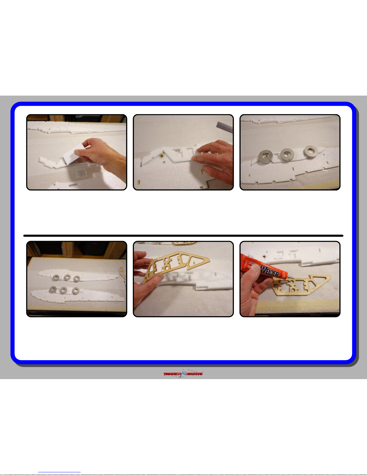
Start with the pieces shown above. This
will assemble into the Battery Box.
Locate all the internal bulkheads and
separate them into their individual
pieces.
Add a drop of thin CA from this side
and hit with Kicker. This will keep the
screws from backing out over time.
Page 14
Rev: 2015.08.16.v01a
page 14
Note the orientation of the parts, Tabs
are keyed, but in some cases there is
more than one way to put these
together. Note the location of the little
hole on the piece to the right.
This piece installs as shown. again
notice the little hole.
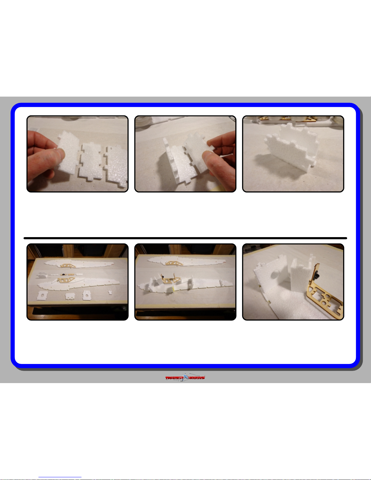
Once you get it all together and you are
happy with the t up, re-assemble with
Welders.
DRY FIT - Notice the orientation of the
front bulkhead, the battery box and the
forward wing mount cross member.
DRY FIT - all the bulkheads to one side
of the fuselage as shown.
After the main fuselage pieces have had
time to dry, locate all the parts as
shown and notice how they are all laid
out, this will be the general position in
the fuselage.
Page 15
Rev: 2015.08.16.v01a
page 15
DRY FIT - Notice the orientations of the
rear wing mount cross member and
bulkheads shown.
DRY FIT - the main rear bulkhead.
DRY FIT - the tail section bulkhead.
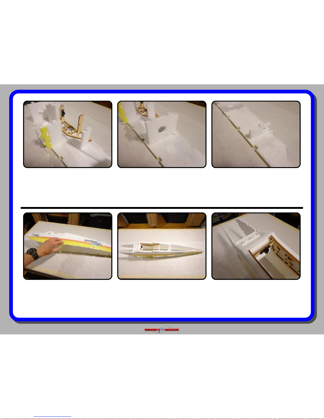
DRY FIT - Close up of the front wing
mount cross member installed.
DRY FIT - looking down from the top,
everything should be pretty square as
assembled if all the tabs and slots have
mated up properly.
DRY FIT - the other side of the fuselage.
Start from the tail and work all the tabs
and notches so that they are all
engaged and fully seated.
Page 16
Rev: 2015.08.16.v01a
page 16
DRY FIT - close up of the rear wing
mount cross member installed.
DRY FIT - Close up of the tail section.
DRY FIT - Locate the belly parts shown.
DRY FIT - the upper nose cover.DRY FIT - the bottom front section.
DRY FIT - the belly pieces into their
location. If everything is assembled
correctly up to this point there should
be no trimming needed.
Page 17

Rev: 2015.08.16.v01a
page 17
DRY FIT - Notice that one side is relief
cut so that the part will bend easily and
t the designated area.
DRY FIT - Look carefully at the nose,
you will see that there is a little
interference were the two pieces come
together. Trim an angle onto the lower
piece, go slow and test t often.
DRY FIT - When you have removed
enough material from the edge of the
lower piece, the top and bottom nose
pieces should t up as shown.
Double check that the servos t. Do not
glue them in at this time, just make
sure the t nice.
If you are satised with the t up of all
the parts, take everything apart,
remembering how it all went together.
DRY FIT - Look everything over, make
sure that it has all gone together
square, that all tabs are fully engaged
and that you have correct orientation of
all the bulkheads.
Page 18

Rev: 2015.08.16.v01a
page 18
Close up of how the servo should be
seated into the cut out in the wood.
Once you are happy with the t up,
remove the servos from their postions.
Start the re-assembly of the fuselage by
putting Welders on all the mating
surfaces between the bulkhead parts
and the fuselage sides.
Then install the bottom and use
masking tape to hold all the parts in
place.
Front section / battery box area shown
above, with masking tape holding
everything together. Set the fuselage
aside now for a couple hours so that
the glue can dry.
Wing saddle area. Also use some
masking tape here to keep all the cross
members tight in their slots.
Nose pieces shown, again masking tape
being used to hold all the seams
together while the glue dries.
Page 19

Rev: 2015.08.16.v01a
page 19
If you have not already done so, now is
a good time to test your electronics.
Above is a picture of a typical layout for
this model.
Create a new model on your radio and
bind per your mfg’s procedures. The
next couple steps will show how to mix
in another channel for the second
motor and which wing conf. to use.
WING TYPE
For this model, pick the “Dual Ail” wing
type and “Normal” tail type.
MIX 3
Used to mix left (port) motor with
rudder, with rudder being the master.
MIX 2
Used to mix right (starboard) motor
with rudder, with rudder being the
master.
MIX 1
Used to control throttle of motor #2
(gear channel). Right motor (starboard)
is plugged into the throttle channel and
the left (port) motor into gear channel.
Page 20

Rev: 2015.08.16.v01a
page 20
Glue the arm extenders onto the back
side of the single sided servo arms. CA
or Welders. Wrap with thread for extra
strength. Large hole may need enlarged
depending on your servos.
Make sure the servos are electronically
centered and mount the arms with
their screws as shown. Servos with
extenders are for the ailerons, the other
two are for the tail surfaces.
If a couple hours have passed already,
the fuselage should have dried enough
now to handle. Carefully remove all the
tape. Check for any loose or open
seams.
Install the rest of the servos.
NOTE - the arms for the tail servos face
to the INSIDE. Also, do not glue the
servos in at this time.
Install the aileron servo as shown, with
the arm extending thru the fuselage.
Waterbug Build Only - remove the
plastic covering from the slot in the
fuselage where the aileron control arms
will protude.
Page 21

Rev: 2015.08.16.v01a
page 21
Locate the four small plastic links as
shown and the small (1mm ID)
threaded ends. Thread the links on so
that there is approx 1/8” of THREAD
still showing for adjustment if needed.
TEMPORARILY mount the links onto
the elevator and rudder servo horn’s
outer most hole. Use a stick pin or
other item that will drop thru the hole
of the connector and horn freely.
Locate the 1mm round push rods and
the white push rod guide tubes as
shown.
Locate the upper rear deck of the
fuselage.
Secure the rod guides with a drop or
two of medium CA at each of the
bulkhead points... hit with Kicker.
Press the push rod GUIDES into their
respective bulkhead slots. They should
line up perfectly when fully seated.
Leave a 30mm gap between the end of
the guide and the end of the ferrule.
Page 22

Rev: 2015.08.16.v01a
page 22
Feed the push rod guides thru the
slots, making sure that they do not get
crossed in the process.
Dry Fit and when happy with how
everything lines up, remove and add
Welders to all the mating surfaces.
Use some small tabs of tape or stick
pins to hold things in place while the
glue dries.
Test t that you have made the slit long
enough.
Cut out the two horns for the tail, the
shorter one with the 4 large lighting
holes is for the elevator, and the longer
one with 5 holes is for the rudder. Cut
the partial slit all the way through.
Locate the tail sections and the G10 kit
with the control horn on it.
Page 23

Rev: 2015.08.16.v01a
page 23
With the nozzle of the Welders tube,
force some glue into the slit, and also
apply a thin coat to the mounting area
of the horn.
Install the horn, wipe away any extra
glue, bend part of the elevator up and
use the crease in the foam as a
reference to line up the holes in the
horn to, as shown above.
Check on the hinge cut out side that
the prole of the horn matches the
prole of the hinge cut.
.... install the horn into the slit and
repeat the process of lining it up like
was done with the elevator.
Flip the rudder over so that the smooth
side of the hinge area is facing you and
with the nozzle of the Welder’s, force
some glue into the slit and coat the
base of the horn...
Locate the slit on the rudder, should be
on the hinge cut side. Make a slit all
the way through. NOTE - the horn will
get installed from the OTHER SIDE.
Page 24

Rev: 2015.08.16.v01a
page 24
Double check that the prole of the
horn is matched up with the prole of
the hinge cut.
Waterbug Build Only - hold the elevator
up to the fuselage and take note of
where the two meet up.
Waterbug Build Only - remove the
laminate material in the area noted.
This is being done so that there will be
a foam to foam joint when the two
pieces are glued together.
Slide the tab of the rudder into the slot
of the elevator... no glue yet.
Next... we will glue the elevator and
rudder together.
Waterbug Build Only - Once you have
slit/scored the laminate, you can peel it
away.
Page 25

Rev: 2015.08.16.v01a
page 25
When you get to about an inch of
clearance, stop there...
... and add some glue to the areas that
will contact each other
Fully engage the two pieces, wipe away
any extra glue.
While the tail is curing... locate the two
wing halves and the wood parts kit.
Set aside and let the glue set up.
Make sure that the two pieces are
square to each other.
Page 26

Rev: 2015.08.16.v01a
page 26
Remove the center wing rib from the kit
as shown above.
Test t the rib into the fuselage as
shown.
The rear tongue and front tab should
both engage without any force.
Once the glue has tacked up, attach the
two pieces. If the prole or the rib does
not match perfectly to the wing, use the
REAR and BOTTOM edges as the ones
to line up ush with.
Use the Tack Up Method.... coat one
side of the rib and the mating surface of
the wing core with a medium skim coat
and let sit for about 5 minutes.
Note how the open area of the wing rib
lines up with the center of the black
plastic nut ange. Later, the included
plastic thumb screw will pass thru this
area and hold the wing in place.
Page 27

Rev: 2015.08.16.v01a
page 27
Snip away the little connector spacers. The Wing Mounting Screw should pass
through freely.
Using the tack up method again, coat
the mating surfaces with a medium
skim coat of Welders and allow to tack
up.
Make sure the push rods are on the
TOP of the elevator.
Once the tail section has dried, it can
be attached to the main fuselage. Test
t everything rst, so you know how it
all goes together.
Once the Welders has tacked up, bring
the two pieces together. Make sure to
align them as accurately as possible.
Page 28

Rev: 2015.08.16.v01a
page 28
Line up the front rudder tab with the
slot in the upper fuselage deck.
Fully engage the tabs of the rudder into
the fuselage. Check to make sure all
the surfaces are meeting up ush.
Once satised with the tment, remove
and add Welders to all the mating
surfaces and re-install while the glue is
wet.
Round up the thick carbon rounds, a
straight edge, a measuring device and a
hobby knife with a fresh blade. The
tops side will be done rst.
Sight down the fuselage and make sure
the tail section is true in all directions.
Check for Squareness
Page 29

Rev: 2015.08.16.v01a
page 29
The object is to cut a slot in the wing to
receive the carbon round. Notice that
there is a notch in the wing rib that is
provided as clearance for the carbon
round.
Using the notch as a reference, line up
your straight edge so that it passes
thru the notch and is parallel to the
wing. If using the leading edge slot as
reference it should be approx 8mm.
Adjust back and forth until you have
the exact same measurement on both
sides of the wing.
Lay the carbon round back into the slot
so that it is just below ush.
Remove the rod and force Welders into
the slot with the nozzle of the tube. If
there is a bunch of built up glue on the
nozzle, clean that off rst so that the
nozzle will “glide” along the slot.
Hold the straight edge rm and cut a
slot approx 2mm deep that is slightly
longer then the round and centered
from side to side. Test t the round into
the slot, it should be just below ush.
Page 30

Rev: 2015.08.16.v01a
page 30
Wipe away any extra glue with a paper
towel. Just go over it once. Repeated
passes will mess up the printed
graphics.
Repeat for the bottom side... cut a slit
2mm deep that is parallel to the wing....
..... squeeze in some Welders....
With the bottom side facing up, make
sure the wing lays at. Add a little
weight to the area around the hinge line
and let it all dry.
.... and wipe away any extra glue with a
single pass.
.... lay in the carbon round to just
below ush...
Page 31

Rev: 2015.08.16.v01a
page 31
Locate the wood parts kit and remove
the remaining parts, which should
make up the motor mounts.
Dry Fit - Notice that there is a notch on
the rewall part, this is the BOTTOM,
locate the wing pieces into their
respective slots, so that the rewall can
be mounded as shown above.
Dry Fit - Do both sided, making sure
that the wing pieces are fully engaged
into the provided slots.
... and from the side. Notice that both
rewalls are inline with each other. It
should also be noted that the rewalls
are pointing slightly upward, this is by
design and is correct orientation.
Make sure everything looks good from
the front.....
Inspect to make sure that the notch in
the rewall is at the bottom.
Page 32

Rev: 2015.08.16.v01a
page 32
Secure all the parts to one another and
to the wing with thin CA and Kicker.
Using the screws provided with the
motor, mount the motors to the
rewall. If using the TH Power Combo
motors, drill the holes out to 1.5mm,
this will keep the wood from splitting.
Repeat with the other motor.
As an option, the ESC’s could be
mounted inside the cabin area, approx
as shown above. Extension wires would
be needed and for safe measure the
ESC’s should still be water proofed.
If deciding to mount the ESC’s outside
the cabin area, no motor extensions
would be needed. Water proof them,
and make sure the wires are buried
where the cross into the fuselage.
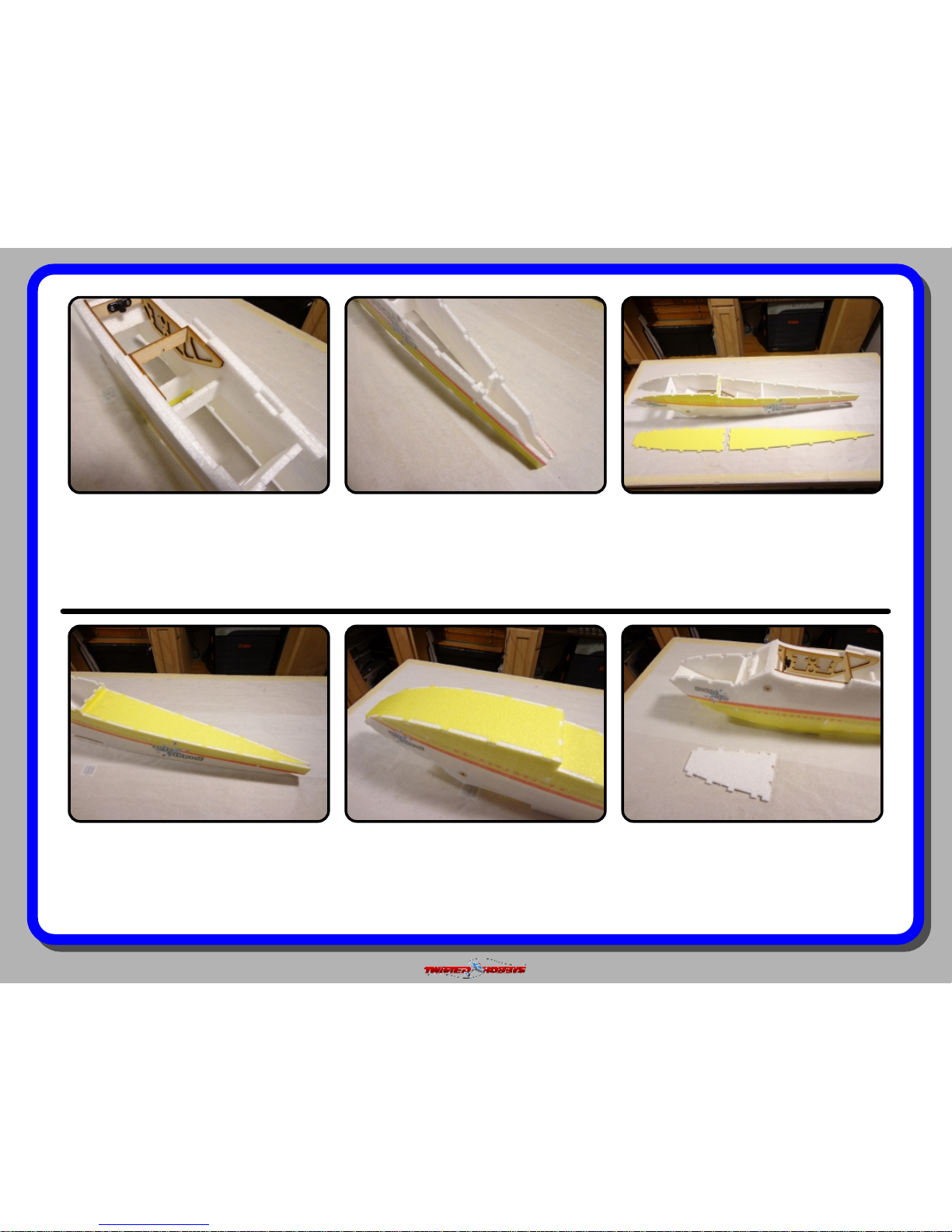
From the bottom of the wing, mark off
an area that is approx 2.50” wide and
centered on the rib. This is the area
inside the cabin.
Page 33

Rev: 2015.08.16.v01a
page 33
If choosing to mount the ESC’s in the
cabin area, some short extensions will
need to be made up, this will be done
shortly in an upcoming step.
Water proong the ESC’s and Rx is
next. Either Plastic Dip or Liquid
Electrical Tape will work. In this build,
Plastic dip will be used for the ESC’s
and Liquid Electrical Tape for the RX.
Read the instructions on the Plastic Dip
Can. Grab one of the ESC’s by the wires
as shown, and dunk it into the can.
You could also dunk the RX, just keep
the pins clear. This build uses Liquid
Electrical Tape. Coat the areas where
the board is exposed and to cracks
where water could get in.
Do both ESC’s. Note at rst it seems
that this is adding a lot of weight, but
one it is all dry, added weight of two
dunks is only a gram or two.
Let some of the extra material drip off.
Set aside for about 30 minutes and
dunk a second time, and again, let the
extra drip off.
Page 34

Rev: 2015.08.16.v01a
page 34
Once the Liquid Electrical Tape has
dried, inspect to verify that all the
components are sealed and covered.
If there is anything exposed, just add a
little more of the Liquid Electrical Tape
to the area in question.
Set everything aside and let dry for the
recommended time.While these are
drying you can make the extensions
needed if you have chosen to mount the
ESC’s inside the cabin.
Once the wires are completely buried,
the exact length of the wire needed to
reach the motor can now be
determined.
Note that the slit to bury the wires will
need to be a little deeper in the area
where the bullets are.
Attach the extensions to the ESC side
and cut some slits so that the wires can
be buried in the wing. Make sure the
ESC’s are still within the marks that
were made earlier.
Page 35

Rev: 2015.08.16.v01a
page 35
Cut the extensions to length and attach
bullets. Protect with heat shrink, clear
heat shrink was used in this build, but
any color could be used.
Make sure the wires are buried deep
enough to allow the motor pod cover to
set ush.
Repeat the process for the other side.
A patch of HD clear tape will be applied
over the area where the wires were
buried. This will add some strength
back. Tape off the area and lay down a
couple beads of Welders...
Now is a good time to make sure motor
direction is correct. The right motor
should be plugged into the throttle
channel and the left motor into the gear
channel. Pull red wire from left ESC.
Mount the ESC’s in position as shown
with a dab of low temp hot glue.
Page 36

Rev: 2015.08.16.v01a
page 36
... and with an old business card,
spread the Welders out to a skim coat
that is about as wide as the HD tape.
Allow the glue to tack. Doing this will
give the HD tape a stronger grip.
Once the glue has tacked up, cut a
piece of clear HD packing tape to t the
area. If you use masking tape to
contain the glue area, it an be removed
now.
Lay the tape down and press rm to get
it all stuck down good. Repeat for the
other side.
Once the glue has tacked up, attach the
covers.
Tack up method will be used to attach
these. Apply a skim coat of Welders to
each of the mating surfaces. Start with
the bottom side.
Cut out all the cowling covers as shown
above.
Page 37

Rev: 2015.08.16.v01a
page 37
Repeat the process for the top side. Completed.
Locate the aileron control surface
horns.
Remove the horn and squeeze in some
Welders. Put a skim coat on the
mounting area of the horn and install.
Test t the horn, make sure the slit is
cut so that the hole in the horn is
allowed to line up directly over the
hinge line.
20mm in from the edge of the aileron,
cut a slit to accept the horn.
Page 38

Rev: 2015.08.16.v01a
page 38
Wipe away any extra glue and double
check alignment with the hinge line.
Repeat for the other side.
Locate the brass ferrules, clevises and
carbon push rods.
Center the rudder.The other ferrule, attaches to the
middle hole of the rudder control horn.
Install the tiny brass pin in far enough
that it snaps into place.
With thin CA, attach the ferrule to one
end of each rod.
Page 39

Rev: 2015.08.16.v01a
page 39
From the end of the ferrule, measure
30mm...
... and cut away the white push rod
guide tube.
Clean out the end of the tube with the
tip of a hobby knife. Repeat this and
the pervious four steps for the elevator.
There should be a little extra carbon
rod as shown, this will be cut away in a
moment.
Repeat for the elevator, and snap them
each onto their respective servo horns
Use the outer most hole, and make
sure the pins are fully engaged.
Take the longer of the two rods that you
just glued the end to, and slide it into
the guide tube for the rudder.
Page 40

Rev: 2015.08.16.v01a
page 40
Slide on one of the two push rod guide
supports.
Just let the guide hang freely for now.
Center the rudder and cut the carbon
rod with a pair of sharp side cutters.
For reference, once the rod is inside the
ferrule, it will extend approx to the area
where the threads start.
Elevator is next... same basic steps.While keeping the rudder centered,
apply a drop of thin CA and let it
wick/run into the ferrule, hit with
Kicker.
Deburr the end where cut and slide into
the ferrule. Make sure that the rudder
is still centered.
Page 41

Rev: 2015.08.16.v01a
page 41
Hold the elevator control surface level,
and cut the rod so that it is just shy of
the threaded area of the ferrule. Slide
on the guide support and leave loose for
now.
Deburr the end of the carbon rod, and
slide onto the ferrule.
Again... while holding the elevator level,
apply thin CA and Kicker as was done
with the rudder push rod.
Thread the clevis and threaded ferrule
together so that the OVERALL length is
1.00 inches.
Locate all the pieces for the aileron
push rods as shown above.
Stick the push rod guide support into
the pre-cut hole and glue with CA and
Kicker. Repeat for the elevator.
installing the guides will cause the
push rods to bow. this is normal.
Page 42

Rev: 2015.08.16.v01a
page 42
Insert the rod into the ferrule and glue
with thin CA and Kicker. Repeat with
the CLEVIS ONLY on the other end of
the control rod.
With the wing attached to the fuselage,
attach the control rod as shown, use
the middle hole on the extended servo
arm. Repeat for the other side.
Locate the two thin carbon strips from
the hardware bag and the SFG,s/Wing
Skids.
Repeat for the other side.In a at, constrained condition, glue
the spar in with thin CA and Kicker.
Insert the carbon strip into the pre-cut
slit.
Page 43

Rev: 2015.08.16.v01a
page 43
Tips are next. It should be noted that
these parts are Depron and FOAM
SAFE glue MUST be used when
attaching them to the Wingtip Skids.
Attach as shown. Apply a couple small
beads of CA to the white part, spray the
tip of the skid with Kicker and join the
two pieces. Parts are cut so their
common edges match and will line up.
Next the Wingtip skids will be
attached... start by applying a bead of
Welders to the slot in the wing and
other mating surfaces
Wipe away any extra glue.Make sure it goes all the way in, and
that it is square to the wing.
While the Welders is still WET, slide the
skid on, with the carbon facing inward.
Page 44

Rev: 2015.08.16.v01a
page 44
Repeat the process for the other side. Locate all the windscreen parts as
pictured above.
Hold the windscreen up to the fuselage
as shown. NOTE THE ORIENTATION.
With a Sharpe, mark where the edges of
the fuselage are.
Attach the allen head screw and plastic
nut as shown. Head of the allen head
screw should be facing INWARD.
Repeat for the other side.
With a straight edge, line up on the
marks and fold the plastic.
Make a mark on the other end as well.
There should be four small marks in
the positions as indicated above by the
arrows.
Page 45

Rev: 2015.08.16.v01a
page 45
Install the windscreen. The heads of the
screws should engage into the little
round wood washers, and held in place
by the magnets.
If you have not already attached all the
wires inside the cabin, you can do that
now. Double check that all the controls
are going the right direction. Don’t
worry yet about the amount of throw.
Double check that the motors are
rotating in the proper direction.
Grasshopper Build - Mask off the sides
as shown in the previous picture and
mist the side and bottom with 3M 77
Spray Contact Glue.
Grasshopper Build - If you skipped the
Waterbug Build waterproong steps at
the beginning of the manual, but intend
to occasionally y off water, you will
need to do these next couple steps.
Don’t forget that when you remove the
wing you MUST REMOVE AT LEAST
ONE END OF THE AILERON CONTROL
ROD.
Page 46

Rev: 2015.08.16.v01a
page 46
Grasshopper Build - Cover the sides
with clear packing tape and trim ush.
Grasshopper AND Waterbug Build -
with Heavy Duty or clear Gorilla tape,
cover the bottom surfaces. Trim ush
and seal the edges with Welders
Hook up all the electronics inside the
Cabin again, and re-check that
everything is functioning normally.
Now is also the time to set the control
throws.... Aileron should be set to
approx ±40 degrees
Make sure and set up a mix so that the
second motor is also controlled by the
throttle cut condition.
If using independent throttle channels
for each of the motors, a mix can be
setup to augment rudder control with
differential thrust.
Page 47

Rev: 2015.08.16.v01a
page 47
This completes the basic build. There are several online
resources available for this specic model, and EPP foamies
in general. One of the best online resources for this model is
the RC Groups thread that was started specically for the
Puddle Star.
RC Groups Puddle Star Build and Discussion Thread
http://www.rcgroups.com/forums/showthread.php?t=2279304
This model is sure to impress your ying buddies, a 3D
capable, twin engine seaplane, and if you decide to create
some mixes for differential thrust, there is a whole new set
of maneuvers waiting for you.
Elevator - set for approx ±45 degrees. Rudder - set for approx ±45 degrees
If using the Twisted Hobbys’ CG
Machine, locate the CG approx 3.50
inches from the LEADING edge of the
wing OR approx 1.00 inch BEHIND the
wing spar.
Double check everything one last time.
Find some pristine snow, a grassy park,
or ultimately a pond of water and have
some fun.
Page 48

Rev: 2015.08.16.v01a
page 48
center of
gravity
control
throws
C.G. - 11.61in from nose of aircraft
Locate all the electronic to achieve
indicated CG point. Using slightly
different sized batteries can also help
with achieving proper CG.
For best 3D performance, balance for
level ight upright and inverted with
little to no elevator input. Also power off
down line should be straight down
without any pull or tuck.
Extreme & 3D
Ailerons: +/- 40 deg
Rudder: +/- 45 deg
Elevator: +/- 45 deg
Expo to suit
Beginner & Sport
Ailerons: +/- 20 deg
Rudder: +/- 25 deg
Elevator: +/- 25 deg
Expo to suit
In order to achieve the control throws as
described for “Extreme and 3D, it is
imperative that the control surfaces,
linkages, rod ends, etc, all move freely
over the entire range, including range
end points.
Failure to do so will result in damage to
either the servos or mechanical
components
11.61 inches
Page 49

Rev: 2015.08.16.v01a
page 49
pre-flight & testing
Motor: Should run smoothly at all stick positions, and transition
smoothly from low to high RPM. If the motor is turning
backwards, reverse two of the three wires between the motor
and ESC. Check that the screws holding the motor to the
airframe are tight and secure.
Flight Controls: Set all to neutral or level positions with sticks
in the neutral positions. Ensure that all controls and linkages
move freely. Double check that all hinged areas are free from
rips or tears. Verify proper control surface directions. Right Roll
is – right aileron up, left aileron down, Left Roll is left aileron up
and right aileron down.
Batteries: Should be fully charged prior to each flight. Watch
tra n smi t ter b a tte r y lev el and f ollo w manu fact ures
recommendations. Motor battery should not be drained any
further than recommended by the manufacture, use a timer to
prevent an over discharged condition.
Radio: All trims should be set to neutral and throttle in the low
position. Check that rate switches and mixes are set properly.
Range Check: With and without the motor running per radio
manufactures instructions. If there is insufficient range or
significant reduction with the motor running, resolve and re-test
before flying.
The fi rst flights should be done with the CG at the
recommended position, and reduced control rates until
comfortable with your handling of the aircraft. As your
experience with the aircraft grows experiment with different CG
points and control rates. After all flights, check the aircraft over
for damage and/or other items that may adversely affect flight
performance.
This Extreme 3D Plane is a full performance aircraft and will
provide hours of entertainment, including the occasional crash.
If, as the result of a crash, the foam tears, simply glue with
Welders or CA. Many pilots prefer Welders because it remains
flexible after drying. CA however, is more suited for the “quick”
repair.
This aircraft can be flown indoors or outdoors. It is however
designed specifically for flying outdoors off of water. Landing
on grass or snow is also an alternative, hard surface landings
should be avoided.
Storage
This EPP plane should be stored resting it's landing gear or
hung from the prop. Storing in other fashions that put stress on
the airframe could cause the airframe to distort. Storage in a
hot car could also cause damage.
Preght Checks Preght Checks
Be safe and enjoy, thank you again for purchasing a Twisted Hobbys’ Product!
Page 50

Rev: 2015.08.16.v01a
page 50
notes and s/u Sheet
Page 51

Rev: 2015.08.16.v01a
page 51
TIPS AND TRICKS
A good building surface is —drop ceiling“ panel from a local hardware store on a nice flat board
Use parchment paper between the areas being glued and your work surface
Heavy flat objects (like books, batteries, etc.) could be used to hold everything flat
When resetting your radio, start with all the ATV‘s or throw volumes at 100%.
Make sure you have set the direction of the servos correctly before attempting t o trim for zero position.
If possible try the servo horns in different locations to determine which position will require the least amount of
sub trim.
Installing the servo horns in thei r final location and attaching quick links to the servos may make servo
installation much easier later.
On the Orange Rx, the negative pin is the one closest to the flat side of the circuit board.
Keep a good supply of sharp knife blades handy when building a foamie airplane.
Use low temp hot glue for gluing electronics, this will allow for easy removal later if necessary. The low temp hot
glue can be “released” by painting” the glue bead wit h an alcohol soaked cotton swab a couple times.
A business card with the corners clipped off can be used as a small square.
Allowing the Welders glue to set for five minutes before assembly will shorten the tack up time, just be sure if
doing it this way that you get the parts into posit ion quickly, as the glue will start to bond on contact. Any joints
that you feel are going to require adjustment , it is best to assembly the pieces while the glue is wet. The Green
(high tack) masking tape works the best when used to clamp things together on an EPP foam airplane.
When gluing the rudder to the fuselage, stick pins could be used to ho ld in position if wanting to handle the
airframe before it is completely dry
A rotary tool with a cutting wheel could be used to produce grooves in fiber glass parts instead of coarse sand
paper. Use a hatch pattern. This creates more bonding area for the glue.
 Loading...