

Page 1

Rev: 2012.12.05.v004a
1
2000/2350kV
motor (
12g - 14g)
6 amp ESC
4 channel radio
2x 3.5g / 1x 4.0g servos
6x3 to 7x3.5 prop
2s 180 to 250mAh battery
USA Distributor
Twisted Hobbys
www.twistedhobbys.com
Wingspan = 24"
Length = 25"
AUW= 90 - 100g
yak
mxs
-c edge
Page 2
Rev: 2012.12.05.v004a
2
TABLE OF CONTENTS
TABLE OF CONTENTSTABLE OF CONTENTS
TABLE OF CONTENTS
Page
WARNING INFORMATION ....................................................................................................................................................... 3
SHIPPING DAMAGE.................................................................................................................................................................... 3
OUR MISSION............................................................................................................................................................................... 3
SAFETY NOTES............................................................................................................................................................................ 4
IMPORTANT: PRIOR TO ANY ASSEMBLY................................................................................................................... 4
KIT CONTENTS............................................................................................................................................................................ 5
OPTIONAL PARTS....................................................................................................................................................................... 6
TOOLS & ADHESIVES NEEDED .............................................................................................................................................. 7
THE BUILD.................................................................................................................................................................................... 8
CENTER OF GRAVITY ............................................................................................................................................................. 21
EXTREME & 3D SET UP PRECAUTIONS 21
CONTROL THROWS................................................................................................................................................................. 21
Extreme & 3D 21
Beginner & Sport 21
PRE-FLIGHT & TESTING ........................................................................................................................................................ 22
P
REFLIGHT CHECKS
22
Motor 22
Flight Controls 22
Batteries 22
Radio 22
Range Check 22
F
LIGHT TESTING
22
S
TORAGE
22
NOTES & S/U SHEET................................................................................................................................................................. 23
TIPS AND TRICKS ..................................................................................................................................................................... 24
Page 3

Rev: 2012.12.05.v004a
3
TWISTED HOBBYS
Website: www.twistedhobbys.com – email: sales@twistedhobbys.com
Thank you for your purchasing a Twisted Hobbys’ model. Please read through the entire manual before beginning to
build this model. If you have any questions please contact us at the above indicated email address.
WARNING INFORMATION
WARNING INFORMATIONWARNING INFORMATION
WARNING INFORMATION
This R/C Aircraft is not a toy! Read and understand the entire manual before assembly. If misused, it can cause serious bodily harm and
property damage. Fly only in open areas, and AMA (Academy of Model Aeronautics) approved flying sites. Do not over look the warnings
and instructions enclosed or those provided by other manufactures’ products. If you are not an experienced pilot and airplane modeler you
must use the help of an experienced pilot or an authorized flight instructor for the building and flying of this model aircraft.
These instructions are suggestions only on how to assemble this model. There are other ways and methods to do so. Twisted Hobbys has
no control over the final assembly, the materials and accessories used when assembling this kit, or the manner in which the assembled
model, installed radio gear and electronic parts are used and maintained. Thus, no liability is assumed or accepted for any damage
resulting from the use of the assembled model aircraft or from this instruction manual including but not limited to direct, indirect,
incidental, special, and consequential damages. By the act of using this user-assembled product, the user accepts all resulting liability. In
no event shall Twisted Hobbys’ liability exceed the original purchase price of the kit.
SHIPPING DAMAGE
SHIPPING DAMAGESHIPPING DAMAGE
SHIPPING DAMAGE
Twisted Hobbys checks each plane before shipping to ensure that each kit is in fine condition. We have no bearing on the condition of any
component parts damaged by use, modification, or assembly of the model. Inspect the components of this kit upon receipt. If you find any
parts damaged or missing, contact Twisted Hobbys immediately. We will not accept the return or replacement of parts on which assembly
work has already begun. Twisted Hobbys reserves the right to change this warranty at anytime without notice.
OUR MISSION
OUR MISSIONOUR MISSION
OUR MISSION
To provide the best products and service to our customers at the lowest prices possible. We take great pride in
our company, our commitment to customer service and in the products we sell. Our online store is designed
to provide you with a safe and secure environment to browse our product catalog.
Thank you for shopping with Twisted Hobbys!
Page 4
Rev: 2012.12.05.v004a
4
SAFETY NOTES
SAFETY NOTESSAFETY NOTES
SAFETY NOTES
Before assembling and flying this model, read carefully any instructions and warnings of other
manufacturers for all the products you installed or used on your model, especially radio
equipment and power source.
Check thoroughly before every flight that the airplanes’ components are in good shape and
functioning properly. If you find a fault do not fly the model until you have corrected the
problem.
Radio interference caused by unknown sources can occur at any time without notice. In such a
case, your model will be uncontrollable and completely unpredictable. Make sure to perform a
range check before every flight. If you detect a control problem or interference during a flight,
immediately land the model to prevent a potential accident.
Youngsters should only be allowed to assemble and fly these models under the instruction and
supervision of an experienced adult.
Do not operate this model in a confined area.
Do not stand in line with, or in front of a spinning propeller and never touch it with any object.
IMPORTANT: PRIOR TO ANY ASSEMBLY
Please Note: after removing kit from shipping box, lay each piece flat on a
hard surface, this will allow the airframe to straighten out if lightly bent
from shipping. Do not worry since EPP is very pliable and can be bent back
if out of shape.
Page 5

Rev: 2012.12.05.v004a
5
kit contents
kit contentskit contents
kit contents
standard parts list
2x - wing half
4x - side force generator
1x - fuselage (3 parts)
1x - canopy
1x - elevator
1x - rudder
2x - .5mm x 3mm x 500mm wing spar
2x - .8mm dia x 330mm control rod
2x - wheel pants
1x - tail skid
1x - hardware pack (see detail)
hardware pack
2x - 1.0mm dia Aileron push rod*
2x - .5mm x 3mm x 145mm landing gear strut
2x - .5mm x 3mm x 99mm (extra)
1x - plastic horn / accessory kit
6x - plastic snap links (2 are extra)
4x - quick link sets
1x - heat shrink tubing
* length may vary depending on the kit
Page 6
Rev: 2012.12.05.v004a
6
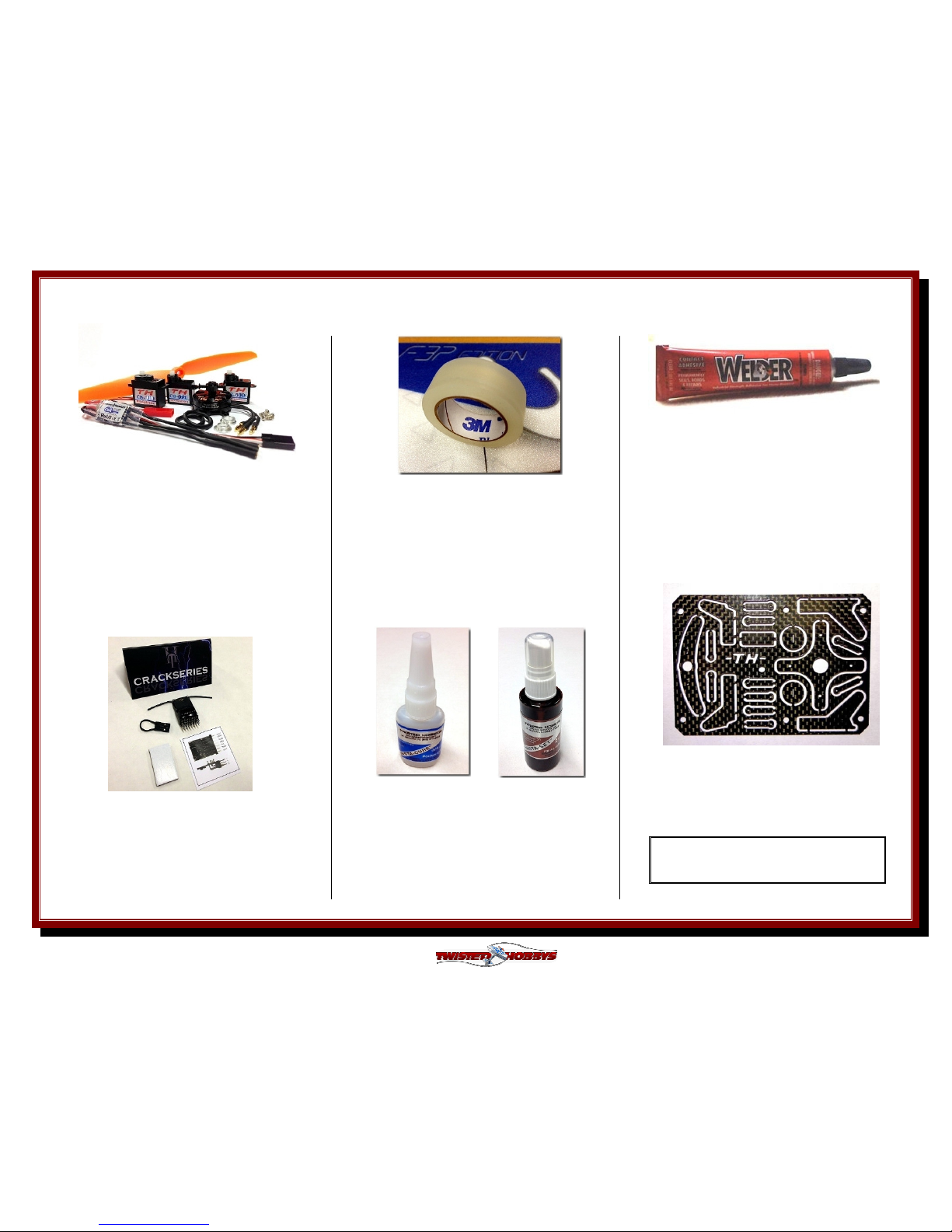
Perfect choice for building and
repairing your Twisted Hobbys
EPP planes! This is the only
adhesive you will ever need.
Welder virtually bonds anything
to anything! Clear, heavy-duty,
flexible and water-proof when
dry. Use indoors or out. (1) 1 oz
tube
Note: many of these “optional parts” shown
or similar items, may be available from the
Twisted Hobbys’ web store.
OPTIONAL PARTS
OPTIONAL PARTSOPTIONAL PARTS
OPTIONAL PARTS
CA and Kicker
Various thickness CA glues
and
Activator available from
Twisted Hobbys’
Blenderm tape is one of the
best know tapes used for
hinging and repairing your
Depron or Epp models. Each
roll consists of 1/2" wide x 4m
in length
Specifications
6 Channel / DSM2 / 2.4GHZ
25mm X 19mm X 11mm
Weight: 3.0g / Input: 3.5–9.6V
Bind plug included
Power Combo Kit
(matched by Twisted Hobbys)
1x - 6a TH-CS ESC
2x - 3.5g servos
1x - 4.0g servo
1x - prop 7x3.5
Carbon bling especially designed
for the Crack Minis
Page 7
Rev: 2012.12.05.v004a
7
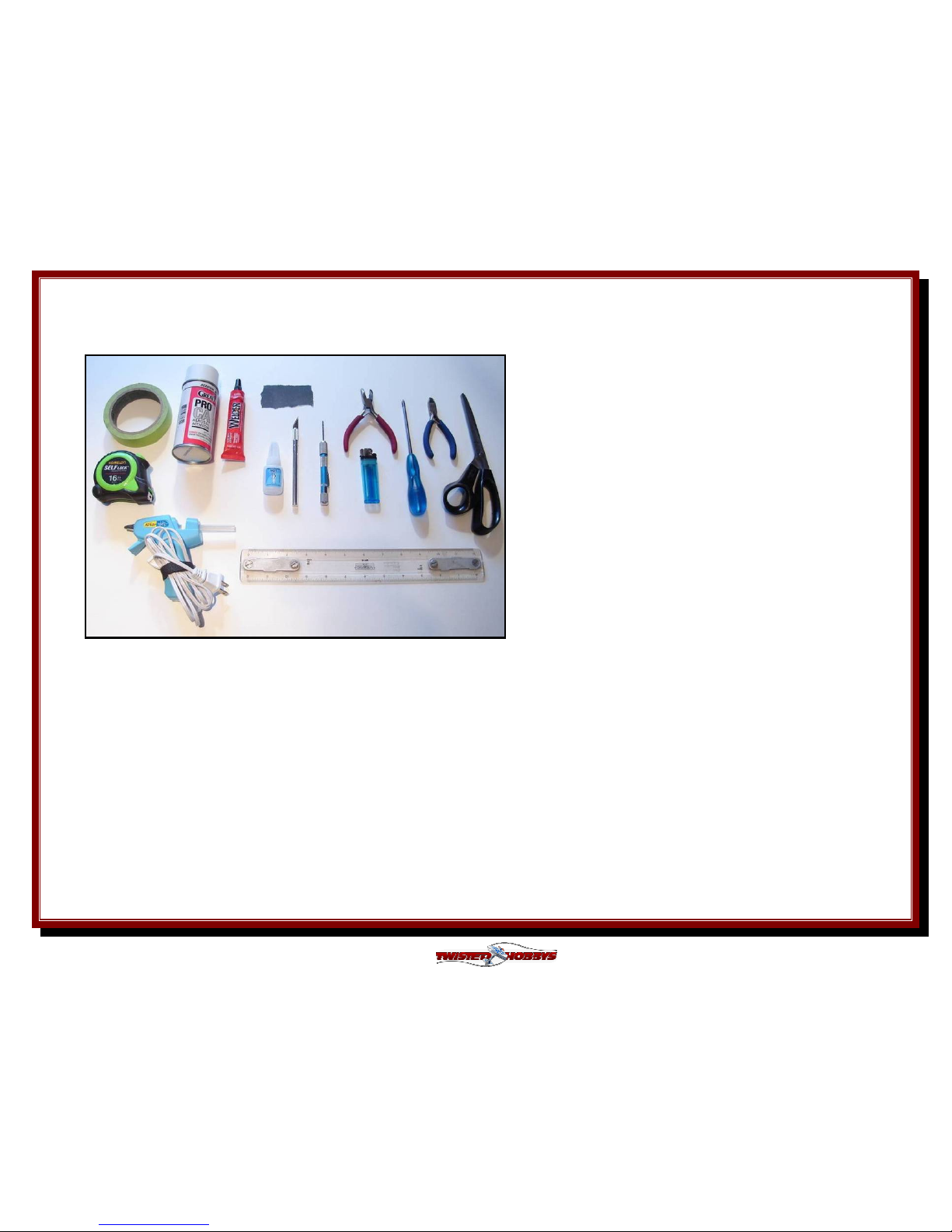
Tools
Tools Tools
Tools &&&& Adhesives Need
Adhesives Need Adhesives Need
Adhesives Needed
eded
ed
• Lighter
• Small drill bits
• Tape Measure and Ruler
• Black Sewing Thread
• Welders Glue
• Hobby Knife w/new Blade
• Needle Nose Pliers
• Wire Cutters
• Low Temp Hot Glue Gun
• Course Sand Paper
• Scissors
• Small Phillips Screw Driver
• Thin & Medium CA
• CA Applicator Tips
• Activator
Tools shown and listed are suggestions only
. D
epending
on your building technique you may not need everything
indicated – and/or – you may find that other tools
available to yourself may be of benefit to your Build.
It is also recommended that you have a flat building
surface, one that will accept stick pins and push pins.
An Acrostic Ceiling panel from your local hardware store
fits this bill nicely, and will lay flat on your work table.
Over size / long push pins are available at your local
craft store. These two items are by no means required,
but will aid in the building process, and can be used for
future projects.
Page 8

Rev: 2012.12.05.v004a
8
THE BUILD
THE BUILDTHE BUILD
THE BUILD
CONSTRUCTION METHODS:
Building surface should be at least 2ft x 4ft and flat. Weights or some small heavy objects will be handy for holding things in place during
the time glue is setting.
Welders glue is the primary adhesive used for this build. The Rod Guides and End Links use thin CA with Applicator and Activator. When
using the Welders glue for a butt joint, apply a thin film to each surface, allow to sit for approx five minutes and then assemble.
Note that this method will create a nearly instant bond, so locate carefully when bringing the two pieces together. If alignment is
necessary or a slip joint, do not allow the glue to tack up, simple apply and join immediately, you will have several minutes to locate the
two parts before the glue sets up. In most cases the parts being glued can be handled with care in 30 minutes, full cure is approx 24
hours.
Open up you kit and inspect for damage and / or missing
parts. Use the Parts List on page 5 to verify that your kit is
complete.
Do the same with the Power Set, confirm that you have all
your items and that they appear to be in sound condition.
Testing of functionality will be one of the first steps that will
follow shortly.
Page 9

Rev: 2012.12.05.v004a
9
Start the build by folding all the hinged
control surfaces back on themselves
and hold the position with some weight
Since the snap links need to dry over
night, build them now
Insert the end of the control rod that
the snap link will be glued to, about
3/8" into the nozzle of the Welders tube
and twist to get an even coat of glue
Remove from the tube and check that
you have an even medium coat of
Welders on the end of the control rod
Locate
the glued end of the rod onto the
saddle area of the plastic snap link. For
the Tail push rods, fully engage the rod
in the saddle area. For the aileron
control rods, see the next step....
... adjust the link onto the end of the
aileron control rod so that the over all
length from the center of the snap link boss
to the end of the rod is at minimum the
dimension above for your model
Page 10

Rev: 2012.12.05.v004a
10
Hook up all the electronics, center and
test. Mount the control horns and
install the quick links as shown in the
outer most holes. Aileron horn is glued
on as shown in the next step
Glue the plastic ailerion differencial
horn on to the UNDER side of the
double sided stock horn as shown. (this
is required to LG clearance). Let the
glue cure before adding the quick links
Tack up method will be used to attach
the canopy to the top half of the
fuselage. Lay a bead on the canopy,
bring the two parts together to
distribute the glue, than seperate.
Carefully bring the two parts together,
notice that the canopy material is a
little thinner, so center it on the mating
edge of the upper fuselage section
Photo showing how the canopy is to be
located in the center of the thickness of
the upper fuselage section
Use the tack up method to attach the
wings and elevator
Page 11

Rev: 2012.12.05.v004a
11
On
ce the glue has tacked up, bring the
wing halves together, make sure the
tabs are all lined up
Prepare the two rectangle wing spars to
be installed. It is easier to temporarily
tack them together with CA before
installing into the slot in the wing
Lay the spars together with their edges
touching and place a small drop of CA
approx every 2 inches
Apply a mist of kicker...
... wipe away any extra CA and kicker...
allow the CA to setup for a couple
seconds before handling. This should
hold them together until installed into
the wing
Mini YAK
: Free the tabbed areas of
the wing spar slot.
Mini MXS:
Free the tabed areas AND
split the fuse as required for the spar.
Page 12

Rev: 2012.12.05.v004a
12
Check that the slot is clear and test fit
the spar assembly
Apply a medium coat o
f Welders to both
sides fo the spar assembly
While spreading the foam, lay the spar
assembly into position
Once the spar is fully inserted, make
sure that there are no gaps between the
foam slot of the wing and the spar. Use
weights, tap and or stick pins to hold
everything tight. Let dry.
After the spar has been allowed to dry,
the top vert. fuselage section can be
installed. Attach this piece using the
WET glue method. Keep approx 1/4"
around the tail servo areas free of glue.
With a small square or other similar
item, verify that the vert. fuselage
section is perpendicular to the horiz.
assembly.
Page 13

Rev: 2012.12.05.v004a
13
Once the upper fuselage has had a
chance to dry, flip the airframe over
and prepare to install the aileron
control horns
Clean up the precut slot to allow the
horn to be completely seated flush with
the bottom and ...
... so that the profile of the horn
matches the profile of the cut out
hinged area
Install the aileron servo into the large
slot. Note that the output arm will be
towards the nose and the horn
oreintat
ion should be as shown. Do not
use any glue on the servos at this time
Servo should sit flush on the mounting
ears. Feed the wire through on the side
shown. Make sure the servo is
electronically centered and that you
have installed the servo horn screw
Install the rudder servo from the top
side, insert as shown. Push the foam of
the vert. fuse slightly off to the side so
that the servo ears can slip underneath
Page 14

Rev: 2012.12.05.v004a
14
View of the rudder servo full seated into
it's designated area. With the aircraft
upright, t
he output shaft is towards the
nose and the arm sticks out the left
side
Install the elevator servo as shown.
Again with the output shaft towards the
nose and servo are pointing up. Route
all the wires to one side as shown
Test fit t
hen glue the lower vert. fuse as
shown. Use the WET glue method for
this step. Make sure the fuse section
fits flush every where
Once all the tabs are fully engaged and
everything is flush, check for
squareness along the length of the
piece, once satisfied, allow to dry
Locate the motor mount and apply a
medium skim coat to the back of the
motor mount and the mating area of
the fuselage nose
Once the glue has tacked up, attach as
shown. Make sure and line up the tabs
of the motor mount with the foam
thickness edges
Page 15

Rev: 2012.12.05.v004a
15
Attach the rudder using the tack up
method. Line up the slit in the rudder
with the mating top edge on the fuse,
there will be a step on the bottom this
is okay and intended
Locate the shorter of the two tail control
horns and
install into the precut slot. It
may be necessary to cut the slot a little
deeper. Make sure the horn in the
hinge area lines up with the foam
Longer horn is used on the rudder.
Install same as the elevator. See the
next picture for how the horns should
look when in the proper location
View showing how the profile of the
horn should match the profile of the
foam when installed in the proper
location
By now your snap links and control
rods should have had the chance to dry
for 24 hours. Locate the guides and
prepare to install
Slide the guides onto the rod, insert the
rod thru the quick link on the servo
and snap the snap link into the hole of
the control horn
Page 16

Rev: 2012.12.05.v004a
16
Put a dab of Welders into each of the precut
holes, install the guides and align them all by
looking down the length of the rod. If using CA
install the guides first, align, then a drop of CA
at the base of each guide
Clip off the extra control rod length.
Leave about 1/2" extra in case you ever
need to redo the snap link end. .
Slightly tighten the screw, too much
will crush the rod
Install the aileron push rods. Make
sure the servo is electonically centered
and the the ailerons are level with the
horz. fuselage section. Slightly tighten
the screw, too much will crush the rod.
Over view showing how the horn should
be perpendicular to the fuselage with
the ends pointing forward as well as
both control surfaces being level with
the horz fuselage section
Land gear struts are next. Find the two
carbon rectangles and small plastic
bulkhead as pictured above
Squeeze a small amount of Welders into
the extreme upper and lower (narrow
areas) of the LG slot, leave the wide
area free of glue at this time
Page 17

Rev: 2012.12.05.v004a
17
Slide the LG struts through as shown.
There are small slits in the horz. fuse
section to recieve the ends.
Once satisfied, use the nozzle of the
Welders tube and squeeze some glue
into the horz. fuse slots and the vert.
fuse area. Wipe away any extra glue.
After the struts have had time to dry,
we will add the front (gym floor) wheels
and rear skid. Welders or Medium CA,
if using Welders, let each step dry
completely before moving to the next
Glue the round doublers onto the
struts as shown. Leave about 1/8"
sticking out. Make sure that the are
both perpendicular to the wing and
parallel to each other
Once the doublers have dried attach
the wheel/wheel pant, centering the
doubler on the round part of the pant.
Make a small slit for the in the pant for
the extra cabon to go into
Attach them both. Again check that
they are square to the wing. Bottom
edge of the pant should (roughly) be
parallel to the bottom of the wing
Page 18

Rev: 2012.12.05.v004a
18
Using the tack up method, attach the
tail skid as shown. Front edge of the
skid should line up with the small
notch from where the rudder and fuse
meet up
Locate the SFG's and cut them free of
each other
Slit each of the SFG's as shown above,
there are small notches to help locate
the center of the tab. Note -
only cut the
small tab, leave the front of the SFG in
tact
Apply a thin bead of Welders to the area
where the SFG and Wing meet, as well
as some in the slot. Smaller SFG goes
outboard. Repeat for both wings. Make
sure they are square as the glue dries
OPTIONAL BLENDERM MOD
Use Blenderm to re-enforce the ends of all
the hinge lines. Also use some around the
tabs of the motor mount.... Skim coat of
Welders under the tape makes it stick
much better
Installation of the motor and esc are
next
Page 19

Rev: 2012.12.05.v004a
19
Mount the motor with the included
screws. Make sure and route the wires
to the side you are going to install the
ESC on
Determine where you want to locate the
ESC and Receiver
Completed Electronics. Use a dab or
two of hot glue to hold the wires in
place
If you did not already set up a program
at the begining of the build, do so now
Set the CG to 2.375"
as measeared from
the leading edge closet to the fuselage.
Adjust battery location as required for
balance
Set the elevator and rudder throws up
to approx 50 degrees in each direction,
ailerons should be set to 40 degrees,
make sure there is not binding or
overload of the servos.
Page 20

Rev: 2012.12.05.v004a
20
FINISHING TOUCHES
Tuck all the wires away and clean
up any glue strings that are left
over from the assembly process.
Double check that all the glue
joints are robust and secure.
Verify that servos are not stalling
at the extreme ends of travel.
Double check that all control
movements are in the proper
direction for command input
Congratulations, this completes the build. Don't let the size of these planes fool you,
they have higher wing loading than their big brothers, so they are very solid in the
air. Hang on when you bang the aileron stick, roll rates at full travel are insanely fast
with these airframes, make sure you have plenty of expo programmed in for the
initial flights. With the higher wing loading, these Minis don't mind a little breeze, but
if you have a basket ball court (or larger) indoor venue these models will really
shine. Adjust your program to suit and enjoy!
Another really good source of information for these and other Twisted Hobbys'
planes is RCGroups.
Page 21

Rev: 2012.12.05.v004a
21
Center of
Center of Center of
Center of
Gravity
GravityGravity
Gravity
EXTREME & 3D SET UP PRECAUTIONS
In order to achieve the control throws as
suggested above described for “Extreme &
3D”, it is imperative that the control
surface, linkages, rod ends, etc, all move
freely over the entire range, including range
end points.
Failure to do so will result in damage to
either the servos or mechanical
components
Control Throws
Control ThrowsControl Throws
Control Throws
Extreme & 3D:
Ailerons - approx +/- 40 deg
Rudder - approx +/- 50 deg
Elevator - approx +/- 50 deg
Expo to suit
Beginner & Sport:
Ailerons - approx +/- 20 deg
Rudder - approx +/- 20 deg
Elevator - approx +/- 20 deg
Expo to suit
Edge 540 mini
5.900”
MXS-C mini
6.300”
Crack Yak mini
6.500”
Locate battery and other components as needed to
achieve the CG point as indicated above for the model
you are building.
Page 22

Rev: 2012.12.05.v004a
22
PRE
PREPRE
PRE----FLIGHT & testing
FLIGHT & testingFLIGHT & testing
FLIGHT & testing
Preflight Checks
Motor:
Should run smoothly at all stick positions, and
transition smoothly from low to high RPM. If the motor is
turning backwards, reverse two of the three wires between
the motor and ESC. Check that the screws holding the
motor to the airframe are tight and secure.
Flight Controls:
Set all to neutral or level positions with
sticks in the neutral positions. Ensure that all controls and
linkages move freely. Double check that all hinged areas are
free from rips or tears. Verify proper control surface
directions. Right Roll is – right aileron up, left aileron down,
Left Roll is left aileron up and right aileron down.
Batteries:
Should be fully charged prior to each flight.
Watch transmitter battery level and follow manufactures
recommendations. Motor battery should not be drained any
further than recommended by the manufacture, use a timer
to prevent an over discharged condition.
Radio:
All trims should be set to neutral and throttle in
the low position. Check that rate switches and mixes are
set properly.
Range Check:
With and without the motor running per
radio manufactures instructions. If there is insufficient
range or significant reduction with the motor running,
resolve and re-test before flying.
Flight Testing
The first flights should be done with the CG at the
recommended position, and reduced control rates until
comfortable with your handling of the aircraft. As your
experience with the aircraft grows experiment with different
CG points and control rates. After all flights, check the
aircraft over for damage and/or other items that may
adversely affect flight performance.
This Extreme 3D Plane is a full performance aircraft and
will provide hours of entertainment, including the
occasional crash. If, as the result of a crash, the foam
tears, simply glue with Welders or CA. Many pilots prefer
Welders because it remains flexible after drying. CA
however, is more suited for the “quick” repair.
This aircraft can be flown indoors or outdoors. It is the
perfect size for the local park or school yard.
Storage
This EPP plane should be stored resting it's landing gear or
hung from the prop. Storing in other fashions that put
stress on the airframe could cause the airframe to distort.
Storage in a hot car could also cause damage.
Be safe and enjoy, thank you again for purchasing a Twisted Hobbys’ Product!
Page 23

Rev: 2012.12.05.v004a
23
NOTES
NOTESNOTES
NOTES & s/u Sheet
& s/u Sheet & s/u Sheet
& s/u Sheet
Page 24

Rev: 2012.12.05.v004a
24
TIPS AND TRICKS
TIPS AND TRICKSTIPS AND TRICKS
TIPS AND TRICKS
• A good building surface is “drop ceiling” panel from a local hardware store on a nice flat board
• Use parchment paper between the areas being glued and your work surface
• Heavy flat objects (like books, batteries, etc.) could be used to hold everything flat
• When resetting your radio, start with all the ATV’s or throw volumes at 100%.
• Make sure you have set the direction of the servos correctly before attempting to trim for zero position.
• If possible try the servo horns in different locations to determine which position will require the least amount of
sub trim.
• Installing the servo horns in their final location and attaching quick links to the servos may make servo
installation much easier later.
• On the Orange Rx, the negative pin is the one closest to the flat side of the circuit board.
• Keep a good supply of sharp knife blades handy when building a foamie airplane.
• Use low temp hot glue for gluing electronics, this will allow for easy removal later if necessary. The low temp hot
glue can be “released” by painting” the glue bead with an alcohol soaked cotton swab a couple times.
• A business card with the corners clipped off can be used as a small square.
• Allowing the Welders glue to set for five minutes before assembly will shorten the tack up time, just be sure if
doing it this way that you get the parts into position quickly, as the glue will start to bond on contact. Any joints
that you feel are going to require adjustment, it is best to assembly the pieces while the glue is wet. The Green
(high tack) masking tape works the best when used to clamp things together on an EPP foam airplane.
• When gluing the rudder to the fuselage, stick pins could be used to hold in position if wanting to handle the
airframe before it is completely dry
• A rotary tool with a cutting wheel could be used to produce grooves in fiber glass parts instead of coarse sand
paper. Use a hatch pattern. This creates more bonding area for the glue.
 Loading...