

Page 1

Rev: 2013.10.19.v002b
1
Superlite
Superlite Superlite
Superlite Indoor Series
Indoor SeriesIndoor Series
Indoor Series
13g - 18g motor / 30
-
50 watts
6 - 10 amp ESC
4 channel radio
2x 4g - 6g servos
1x 8g - 11g servo
7in - 8in prop
USA
Distributor
Twisted Hobbys
www.twistedhobbys.com
YAK
Wingspan = 32"
Length = 31"
AUW= 12
6g -
135g
INFERNO
Wingspan = 34"
Length = 35"
AUW= 126g - 135g
Page 2
Rev: 2013.10.19.v002b
2
TABLE OF CONTENTS
TABLE OF CONTENTSTABLE OF CONTENTS
TABLE OF CONTENTS
Page
WARNING INFORMATION ........................................................................................................................................................3
SHIPPING DAMAGE..................................................................................................................................................................... 3
OUR MISSION ................................................................................................................................................................................3
SAFETY NOTES.............................................................................................................................................................................4
IMPORTANT: PRIOR TO ANY ASSEMBLY....................................................................................................................4
KIT CONTENTS.............................................................................................................................................................................5
OPTIONAL PARTS........................................................................................................................................................................ 6
TOOLS & ADHESIVES NEEDED ............................................................................................................................................... 7
THE BUILD ..................................................................................................................................................................................... 8
CENTER OF GRAVITY .............................................................................................................................................................. 34
EXTREME & 3D SET UP PRECAUTIONS 34
CONTROL THROWS ..................................................................................................................................................................34
THROTTLE CURVE....................................................................................................................................................................34
PRE-FLIGHT & TESTING .........................................................................................................................................................35
P
REFLIGHT CHECKS
35
Motor 35
Flight Controls 35
Batteries 35
Radio 35
Range Check 35
F
LIGHT TESTING
35
S
TORAGE
35
NOTES & S/U SHEET.................................................................................................................................................................. 36
TIPS AND TRICKS....................................................................................................................................................................... 37
Page 3
Rev: 2013.10.19.v002b
3
TWISTED HOBBYS
Website: www.twistedhobbys.com – email: sales@twistedhobbys.com
Thank you for your purchasing a Twisted Hobbys’ model. Please read through the entire manual before beginning to
build this model. If you have any questions please contact us at the above indicated email address.
WARNING INFORMATION
WARNING INFORMATIONWARNING INFORMATION
WARNING INFORMATION
This R/C Aircraft is not a toy! Read and understand the entire manual before assembly. If misused, it can cause serious bodily harm and
property damage. Fly only in open areas, and AMA (Academy of Model Aeronautics) approved flying sites. Do not over look the warnings
and instructions enclosed or those provided by other manufactures’ products. If you are not an experienced pilot and airplane modeler you
must use the help of an experienced pilot or an authorized flight instructor for the building and flying of this model aircraft.
These instructions are suggestions only on how to assemble this model. There are other ways and methods to do so. Twisted Hobbys has
no control over the final assembly, the materials and accessories used when assembling this kit, or t he manner in which the assembled
model, installed radio gear and electronic parts are used and maintained. Thus, no liability is assumed or accepted for any damage
resulting from the use of the assembled model aircraft or from this instruction manual including but not limited to direct, indirect,
incidental, special, and consequential damages. By the act of using this user-assembled product, the user accepts all resulting liability. In
no event shall Twisted Hobbys’ liability exceed the original purchase price of the kit.
SHIPPING DAMAGE
SHIPPING DAMAGESHIPPING DAMAGE
SHIPPING DAMAGE
Twisted Hobbys checks each plane before shipping to ensure that each kit is in fine condition. We have no bearing on the condition of any
component parts damaged by use, modification, or assembly of the model. Inspect the components of this kit upon receipt. If you find any
parts damaged or missing, contact Twisted Hobbys immediately. We will not accept the return or replacement of parts on which assembly
work has already begun. Twisted Hobbys reserves the right to change this warranty at anytime without notice.
OUR
OUR OUR
OUR MISSION
MISSIONMISSION
MISSION
To provide the best products and service to our customers at the lowest prices possible. We take great pride in
our company, our commitment to customer service and in the products we sell. Our online store is designed
to provide you with a safe and secure environment to browse our product catalog.
Thank you for shopping with Twisted Hobbys!
Page 4

Rev: 2013.10.19.v002b
4
SAFETY NOTES
SAFETY NOTESSAFETY NOTES
SAFETY NOTES
Before assembling and flying this model, read carefully any instructions and warnings of other
manufacturers for all the products you installed or used on your model, especially radio
equipment and power source.
Check thoroughly before every flight that the airplanes’ components are in good shape and
functioning properly. If you find a fault do not fly the model until you have corrected the
problem.
Radio interference caused by unknown sources can occur at any time without notice. In such a
case, your model will be uncontrollable and completely unpredictable. Make sure to perform a
range check before every flight. If you detect a control problem or interference during a flight,
immediately land the model to prevent a potential accident.
Youngsters should only be allowed to assemble and fly these models under the instruction and
supervision of an experienced adult.
Do not operate this model in a confined area.
Do not stand in line with, or in front of a spinning propeller and never touch it with any object.
IMPORTANT: PRIOR TO ANY ASSEMBLY
Please Note: after removing kit from shipping box, lay each piece flat on a
hard surface, this will allow the airframe to straighten out if lightly bent
from shipping. Do not worry since EPP is very pliable and can be bent back
if out of shape.
Page 5
Rev: 2013.10.19.v002b
5
kit contents
kit contentskit contents
kit contents
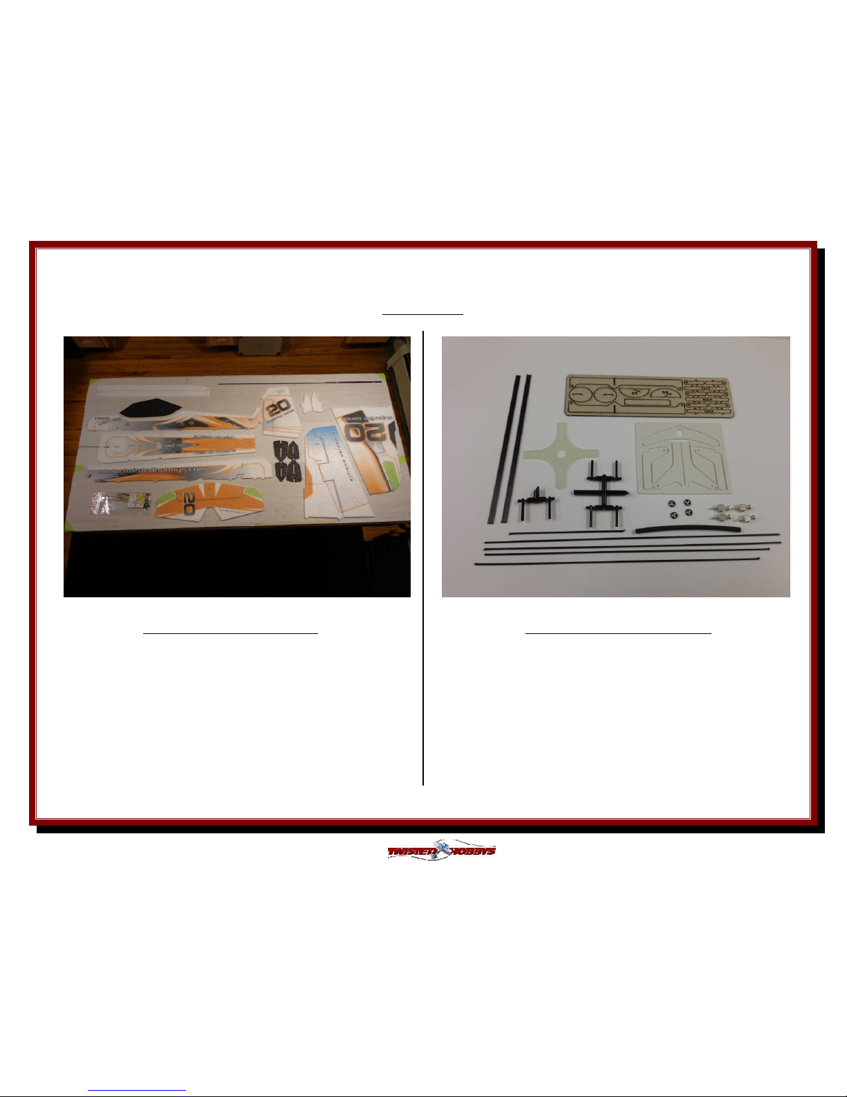
PARTS LIST
AIRFRAME COMPONENTS
1x Wing (2pcs) 2x 1mm x 500mm Round
1x Top Fuse (elev. & rudder control rods)
1x Bottom Fuse 4x 0.75mm x 225mm Round
1x Rudder (aileron stiffeners)
1x Elevator 4x 1mm x 200mm Round
1x Canopy (wing-fuse stiffeners)
2x Wheel/Pant 2x 1mm x 3mm x 198mm Rec
1x Wing SFG Kit (landing gear struts)
2x Fuse Truss 1x 0.5mm x 4 x 667mm Rec
1x Horizontal Fuse (wing spar)
1x Hardware - see detail
DETAIL - HARDWARE PACK
2x 1mm Dia x 150mm Round (Aileron Control Rod)
1x 1mm Dia x 50mm Round
1x 1mm Dia x 60mm Round ( Tail Skid)
2x 0.5mm x 3mm x 100mm Rectangle (Tail Stiffeners)
1x Fiberglass Motor Mount
1x Plastic Kit
1x Wood Horn Kit
6x Snap Link Ends
4x Quick Links with Screws and Keeper Rings
1x Heat Shrink Tube for Z-Bends (approx 65mm long)
Page 6
Rev: 2013.10.19.v002b
6
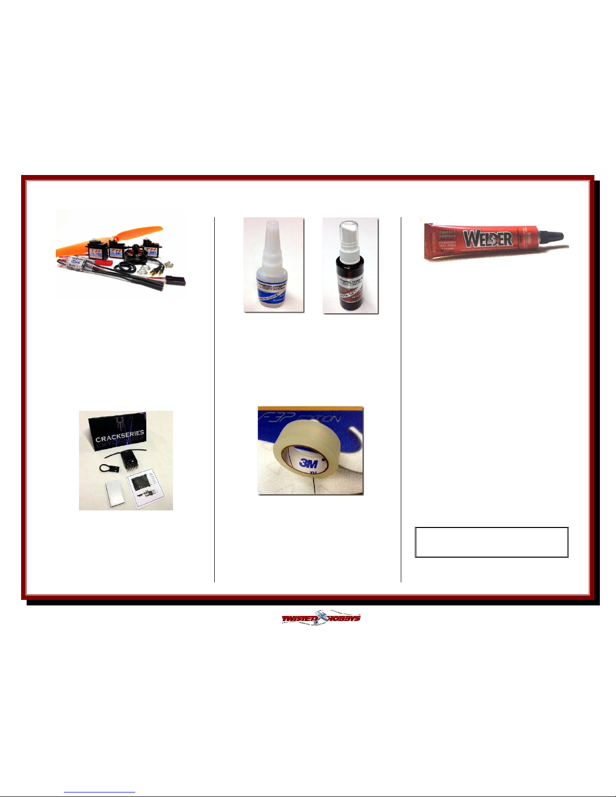
Perfect choice for building and
repairing your Twisted Hobbys
EPP planes! This is the only
adhesive you will ever need.
Welder virtually bonds anything
to anything! Clear, heavy-duty,
flexible and water-proof when
dry. Use indoors or out. (1) 1 oz
tube
Note: many of these “optional parts” shown
or similar items, may be available from the
Twisted Hobbys’ web store.
Crack Power Combo
(Recommended by Twisted Hobbys)
(1) Crack Series 14g - 19g Motor
(1) Crack Series 6A ESC
(2) CS-40D Digital Micro Servos
(1) CS-70D Digital Micro Servo
(1)
7 x 3.5 GWS DD Prop
OPTIONAL PARTS
OPTIONAL PARTSOPTIONAL PARTS
OPTIONAL PARTS
CA and Kicker
Various thickness CA glues
and
Activator available from
Twisted Hobbys’
Blenderm tape is one of the
best know tapes used for
hinging and repairing your
Depron or Epp models. Each
roll consists of 1/2" wide x 4m
in length
Specifications
6 Channel / DSM2 / 2.4GHZ
25mm X 19mm X 11mm
Weight: 3.0g / Input: 3.5–9.6V
Bind plug included
Page 7
Rev: 2013.10.19.v002b
7
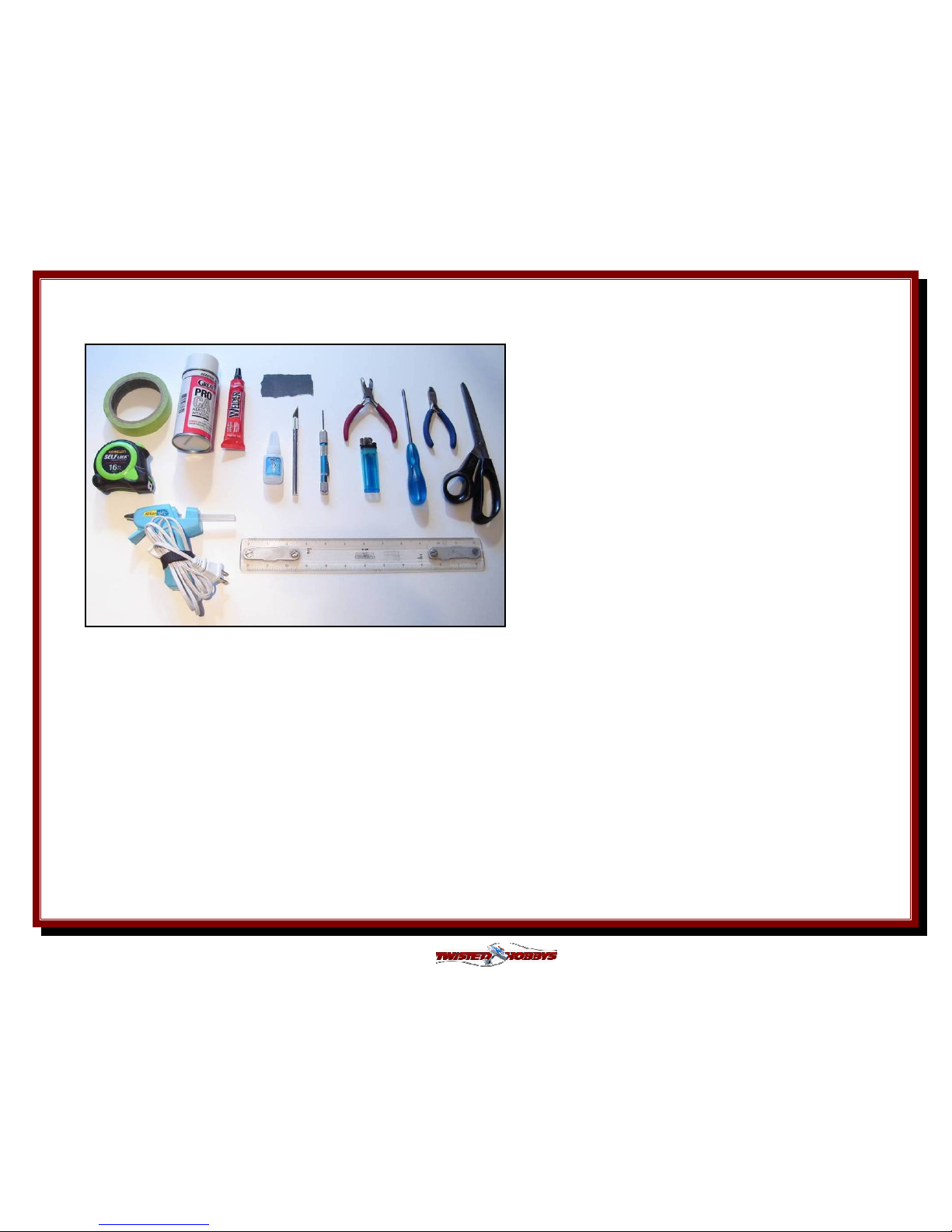
Tools
Tools Tools
Tools &&&& Adhesives Needed
Adhesives Needed Adhesives Needed
Adhesives Needed
• Lighter
• Small drill bits
• Tape Measure and Ruler
• Black Sewing Thread
• Welders Glue
• Hobby Knife w/new Blade
• Needle Nose Pliers
• Wire Cutters
• Low Temp Hot Glue Gun
• Course Sand Paper
• Scissors
• Small Phillips Screw Driver
• Thin & Medium CA
• CA Applicator Tips
• Activator
Tools shown and listed are suggestions only. Depending
on your building technique you may not need everything
indicated – and/or – you may find that other tools
available to yourself may be of benefit to your Build.
It is also recommended that you have a flat building
surface, one that will accept stick pins and push pins.
An Acrostic Ceiling panel from your local hardware store
fits this bill nicely, and will lay flat on your work table.
Over size / long push pins are available at your local
craft store. These two items are by no means required,
but will aid in the building process, and can be used for
future projects.
Page 8
Rev: 2013.10.19.v002b
8
THE BUILD
THE BUILDTHE BUILD
THE BUILD
CONSTRUCTION METHODS:
Building surface should be at least 2ft x 4ft and flat. Weights or some small heavy objects will be handy for holding things in place during
the time glue is setting.
Welders glue is the primary adhesive used for this build. The Rod Guides and End Links use thin CA with Applicator and Activator. When
using the Welders glue for a butt joint, apply a thin film to each surface, allow to sit for approx five minutes and then assemble.
Note that this method will create a nearly instant bond, so locate carefully when bringing the two pieces together. If alignment is
necessary or a slip joint, do not allow the glue to tack up, simple apply and join immediately, you will have several minutes to locate the
two parts before the glue sets up. In most cases the parts being glued can be handled with care in 30 minutes, full cure is approx 24
hours.
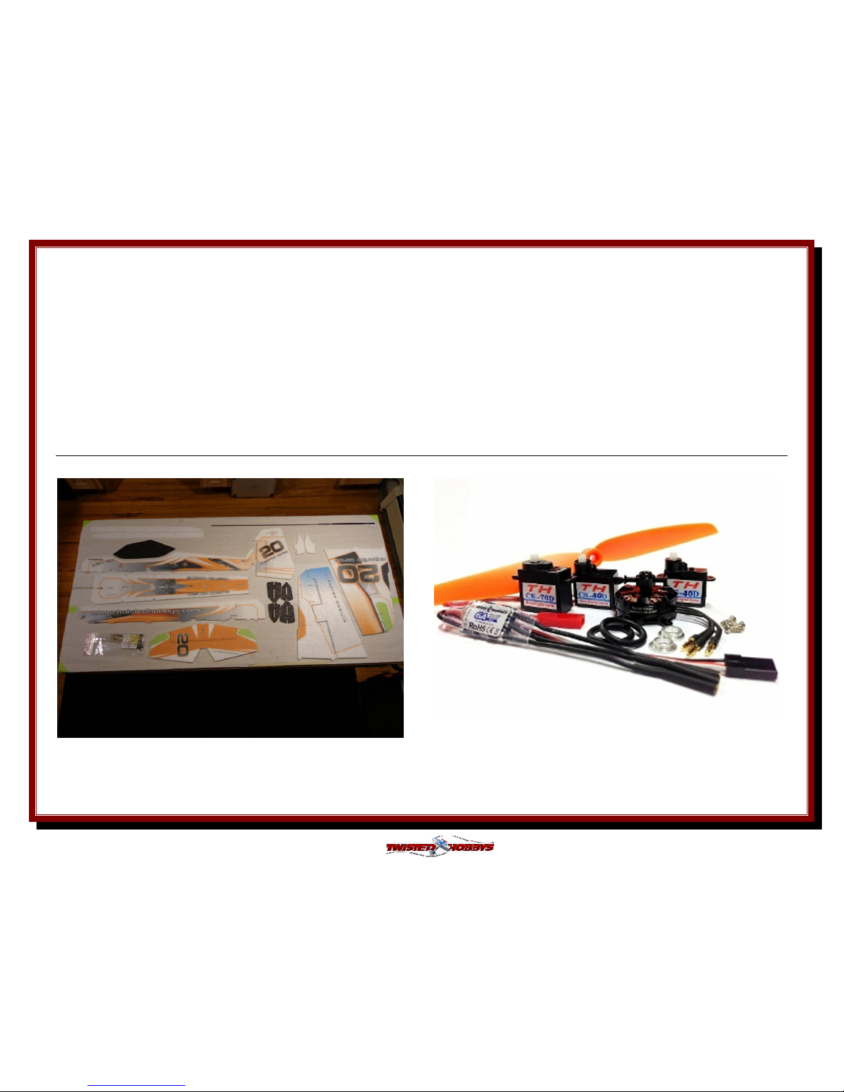
Open up your kit and inspect for damage and / or missing parts.
Use the Parts List on page 5 to verify that your kit is complete.
Do the same with the Power Set, confirm that you have all your
items and that they appear to be in sound condition. Testing of
functionality will be one of the first steps that will follow shortly.
Page 9

Rev: 2013.10.19.v002b
9
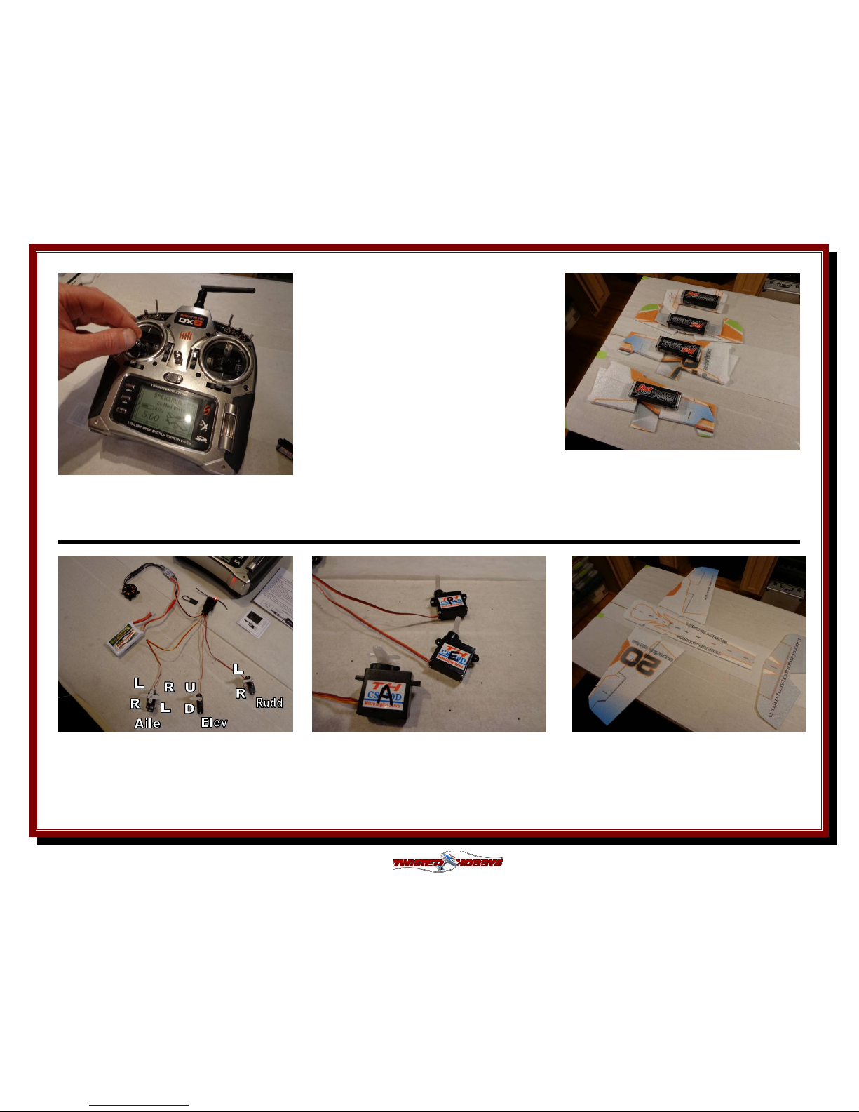
Program the Throttle End Points per the
ESC Instructions and next couple steps….
Identify the porper pins for the; Throttle,
Aileron, Elevator and Rudder Channels.
Carefully compare to the diagram to make
sure you have the correct orientations.
Compare your Reciever to the included
diagram from the side as shown above.
Make a note of the polarity of the pins. In
most cases, either Black or Brown is used
to identify Negative (-).
Make a new program in your Radio. Zero all
the Trims and Subtrims. For starters all the
ATVs can be set to 100% . Adjustment of
additional settings will be done at the end
of the build.
Plug Motor wires into the ESC, the ESC into
the Throttle Channel, and the servos to
their appropriate channel. Bind per your
Radio’s Instructions.
turn on your radio and move the throttle
stick to "full throttle" position...
Page 10
Rev: 2013.10.19.v002b
10
…. reconnect the battery to the ESC
and listen for two quick short beeps,
immediately following the beeps,
move the Throttle stick to low
position.
Next you should hear a series of
tones to indicate that programing is
complete.
Re-
bind the system and double check
correct operation of all components.
Center all servos as close to 90 deg
as possible. Install the Longest single
arms on the servos.
Fold all the hinged parts over onto
themselves and let sit for approx ten
minutes
Mark the Servos with their channel and
install the horn screws
Locate and position the four pieces
shown above
Program your radio so that the
channels & directions match the
picture above. Installed horns as
shown, dbl check that subtrims - arms
should be at 90 deg
Page 11
Rev: 2013.10.19.v002b
11
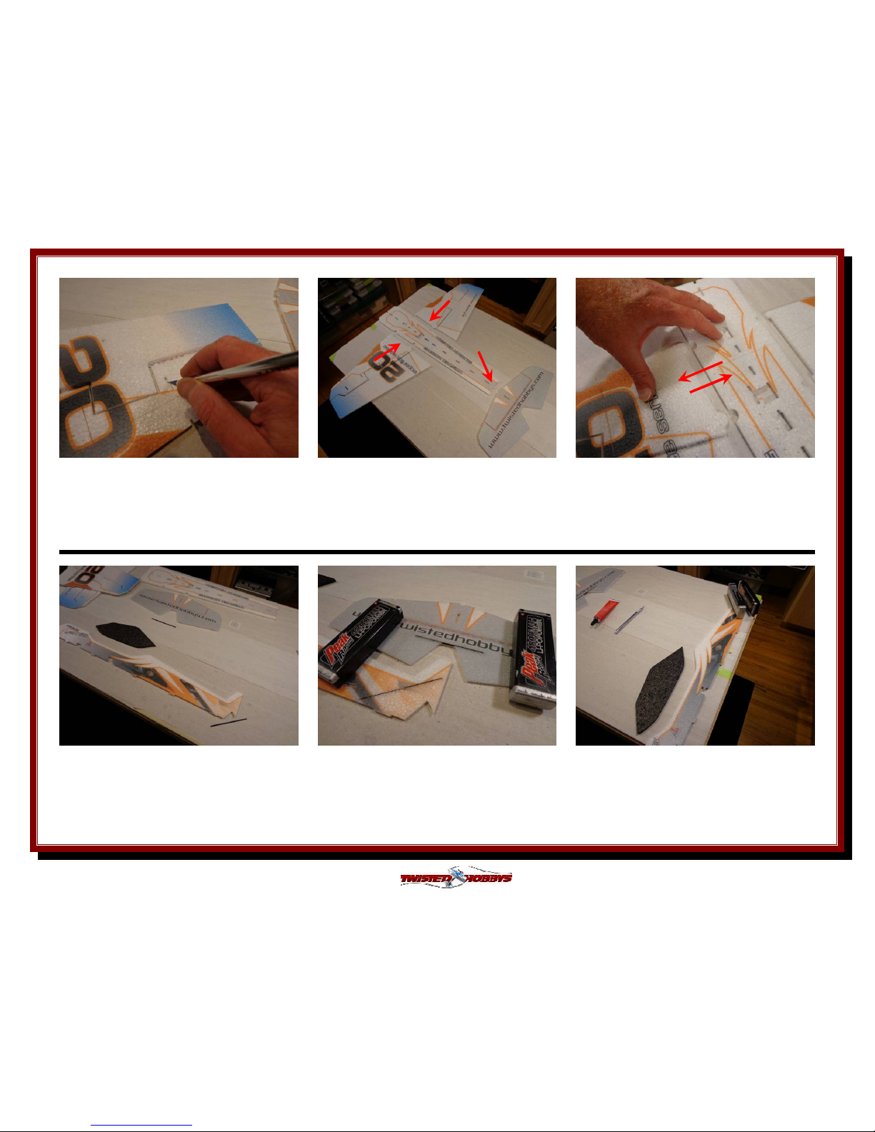
Remove the webs from the areas where
the Side force generators will install
Apply a medium bead of Welders to one
of the pieces of each joint
Join and separate each joint a couple
times to evenly distribute the glue onto
both surfaces, set aside to tack up
While this is tacking up, do the same
with the canopy and fuselage. Also
locate the short carbon strips and test
fit them into their slots.
It may be that the slots need to be
made a little deeper for a flush fit.
Apply some glue into the slot and
install the strips. Weigh down flat and
let dry
Set these aside for while the glue tacks
up for the canopy joint
Page 12
Rev: 2013.10.19.v002b
12
Test / Dry fit the rib and spar pieces,
with the exception of the bumped
areas, everything should be flush with
the bottom of the wing.
By now the glue for the fuselage
horizontal fuselage sections should be
tacked up. Carefully bring them
together, the bond will be instant
Next is the carbon inlays. Locate the
longest strip, the four 225mm rounds
and the wood kit
Find the pre-made slo
ts and cuts for all
the pieces. Notice how the wood rib is
different from front to back
Check that the slot for the Wing Spar is
deep enough, should sit flush. If not
you can gently drag the end of the spar
across the slit to increase the depth
until deep enough
Make sure the slot in the rib allows for
an easy fit of the spar. Enlarge if
necessary with a hobby knife if
necessary
Page 13

Rev: 2013.10.19.v002b
13
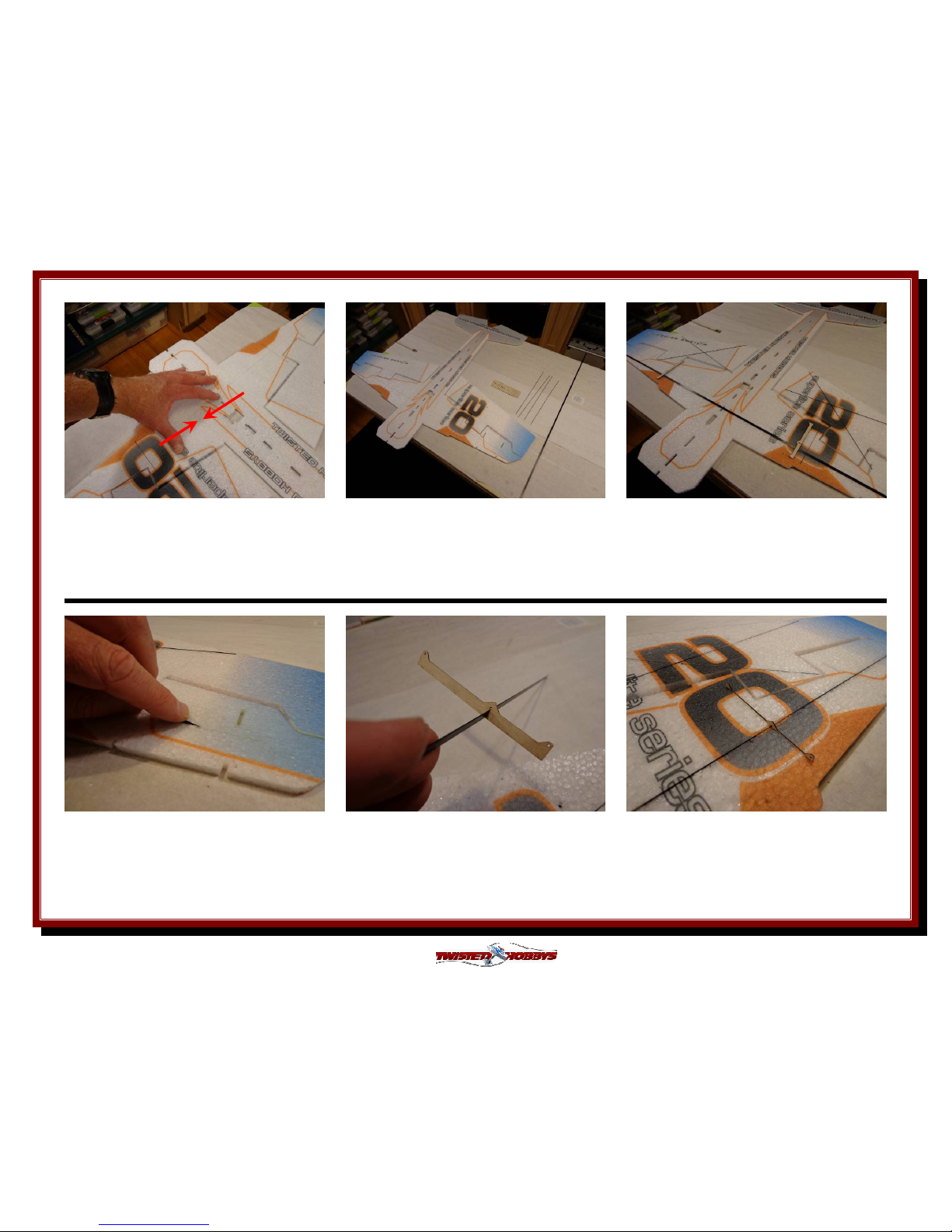
Next test fit the "X" brace pieces into
the slits of the aileron. Note, at the
intersection point one will be a little
deeper then flush
By now the Welder's should be tacked
up on the Canopy. Carefully bring the
two pieces together, lining up the front
and rear points
Back to the wing... remove the pieces
for the "X" brace, and with the tip of the
Welder's tube as show, force a small
amount of Welders into the slit.
Repeat this process for the other aileron
and the wing spar/rib parts. Weigh
down the assembly and allow to dry
Long Push pins could also be used if
you building surface allows for it.
Shown here is an acoustic ceiling tile
on flat surface covered with Parchment
paper
Lay the rod in, and press to flush, wipe
away any extra glue that is forced out
Page 14

Rev: 2013.10.19.v002b
14
Test fit your aileron servo into the
provided cut out. You may need to
enlarge it slightly
If your building board allows for it,
make a small pocket so that the servo
will sit flush on it's ears, otherwise just
hang this part over the edge of the table
Locate the Differential horn from the
plastic kit and 2 sets of the quick links.
Install the quick links into the holes
and secure with the keepers
Once the quick links are installe
d apply
a generous amount of Welders to the
top surface of the servo arm and then
attach the Diff Horn on top of, and
centered as shown, allow to dry.
Locate the small halve moon wood
parts. Note that the notch in the wood
will line up with the notch in the foam.
Off center hole in the wood is to the
rear of the plane
Glue the wood pieces to the fuselage
using the tack up method, making sure
the orientation and notches are correct
and lined up
Page 15

Rev: 2013.10.19.v002b
15
Once the glue is dry on the aileron
differential horn, fit the lower fuselage
section as shown
It may be necessary to slightly enlarge
some areas to allow for a nice fit
Do the same for the for the rudder
servo. Make sure the cut is deep
enough and notch to allow clearance for
the servo wires
Apply a thin bead of Welders to the butt
joint areas on the bottom of the
horizontal fuselage sections. Note - no
glue in the slots at this time
With a small piece of paper or thin
cardboard, spread the bead out into a
thin even layer
Apply glue in the same fashion to the
butt joint area of the lower vertical
fuselage section. Note - no glue on the
tabs at this time
Page 16

Rev: 2013.10.19.v002b
16
Spread the glue bead out as you did on
the mating part, avoiding the tabs. Set
aside and let both parts tack up
While those parts are tacking up, locate
the ailerons control rods (150mm) and
tail control rods (500mm)
as well as the
two tail servos, horns and snap links as
shown above
Start by clipping the snaps links from
the molded tree. Use a small pair of
flush cutters or hobby knife
Dress up the end of the push rod that
you will be gluing the snap link to.
Make sure that the end is nice and
round, not crushed out from the
cutting process
Check to verify a nice fit of the rod into
the saddled area of the snap link
Take the finished end of the rod and
poke it into the glue nozzle to coat with
glue, it may be necessary to do this a
time or two for an even coat of glue
Page 17

Rev: 2013.10.19.v002b
17
Once there is an even coat of glue,
attach it to the saddle area of the snap
link and set aside to dry. Repeat with
the other three control rods
Test fit the aileron control horns. Make
sure and use the one that is shown
above and that the hole will be inline
with the hinge/pivot point
Force some glue into the slit with the
tip of the glue nozzle
Install the horn, making is flush with
the bottom surface and making sure
that the hole is directly above the hinge
line. Wipe away any extra glue. Repeat
for the other side
Install a quick link into the outer most
hole of the longest single sided servo
arm.
Press the keeper ring on, make sure the
quick link can rotate freely. Repeat for
the other tail servo
Page 18

Rev: 2013.10.19.v002b
18
Back to the Fuselage pieces... add some
glue to the tabs and slots
While the glue is still wet on the tabs
and in the slots, join the two pieces
together. Make sure the nose area is
flush
Since part of the joint was tacked up,
the bond here will be instant. Press the
pieces together firmly and make sure
there are no gaps
Wipe away any extra glue. Remember,
for this airframe, the lighter the better,
so remove any extra glue
Make sure everything is square. It can
still be tweaked a little from side to side
if necessary
Next is the foam trusses. Start with the
right underside truss, add a thin bead
of Welders to the entire length of the
beveled edges
Page 19

Rev: 2013.10.19.v002b
19
Install the right under side truss as
shown... use stick pins if necessary to
hole the truss in place while the glue
dries
Repeat for the Left under side truss,
but do not put glue all the way to the
pointed end, see next picture
Leaving this area free of glue will allow
you to tuck all the radio wires away and
out of site later in the build
Bottom Carbon Trussing is next. Find
the four 200mm rods and the two
165mm rods. A .040" dia drill and pin
vise will come in real handy. Read the
next couple steps before proceeding
Dress up both ends of all the rods so
that they are sharply pointed
With the drill, chase the holes in the
wing rib as shown, using the approx
angle that the rod will be installed in for
best results and fit
Page 20

Rev: 2013.10.19.v002b
20
Repeat for the other wing rig hole
Do the same for the mating holes on
the doubler on the fuselage
Once far enough in, line the other end
up with the mating hole in the fuse
double, then back out slightly so that
the fuse end is engaged about half the
foam thickness
Repeat for the other three long pieces.
Note - no glue yet at this point.
Sight down the fuselage, and adjust for
squareness if needed
Stick the carbon rod thru the hole in
the rib, and while holding at the right
angle, twist and poke that end into the
foam far enough to clear the fuse hole
Page 21

Rev: 2013.10.19.v002b
21
Repeat with the rod that angles
backwards. Make sure there is enough
clearance in the doubler hole so that it
can be installed freely.....
.... stick it thru the about 3/16" extra,
then prick the other end into the foam
and feed back into the horz fuse section
approx 3/16". Repeat for the other side
Look every thing over, make sure that
there is about 1/8" or so sticking thru
the doubler in the fuselage, and that
other ends have good bite in the foam
Close up, notice how the rods are
sticking thru the rib and into the foam.
Still no glue at this time
Close up of the other side
Double check that everything is still
square and that all the rod ends are
engaged as they should be
Page 22

Rev: 2013.10.19.v002b
22
Now.. time for glue, back each end in
and out a little so that the glue can
work it's way in and around the rib and
doubler on the other side. Repeat for all
ends and double check squareness
Landing Gear - Locate the two 200mm
strips and the wood pieces shown above
Dry fit everything as shown, make sure
there is clearance for the aileron
differential horn
The wood doubler is in the middle, with
one strut in the front and one in back
Remove the items once satisfied with
the fit. Put a little Welders in the
thinner, top and bottom, area of the
slot...
Re-install the wood doubler and gear
struts, force glue into the area. Make
sure the one end of the strut goes into
the slot on the underside of the
fuselage with some Welders.
Page 23

Rev: 2013.10.19.v002b
23
Make sure that the struts are
intersecting the fuselage symmetrically
and that the horz fuse section is still
square. Wipe away any extra glue
Wheels/Pants are next, cut the foam
apart, and make sure the slit in the
wood pieces is wide enough to clear the
landing gear struts
Glue the wood pieces on as shown. Wet
or tack up method can be used, if time
is critical, use the tack method
While the glue dries on the
Wheel/Pants, prepare the Side Force
Generators
Slit the one end approx in the location
shown above. There are little "v" marks
to help get it split right in the middle
Ready for installation later in the build,
repeat for the other three
Page 24

Rev: 2013.10.19.v002b
24
Once the glue has dried, slit all the way
thru in the area defined by the slot in
the wood doubler
Test fit onto the end of the landing gear
strut. Note, the strut should not stick
out beyond the far side
When both are installed the should be
perpendicular to the work surface and
parallel to each other in the direction of
flight
In this view, the bottoms of the wheel
pant should be parallel with the work
surface, and each other.
Once satisfied with the dry fit, remove
the wheel/pants and force some glue
into the slit with the tip of the tube
Re-install and adjust accordingly in all
directions as was done on the dry fit.
Let all this dry over night
Page 25

Rev: 2013.10.19.v002b
25
Once all the carbon bracing and
landing gear pieces have had time to
dry, remove the assembly from the
bench and flip over onto its wheels
Stick the servos into their appropriate
holes. Note the elevator servo is laying
down with horn sticking up and rudder
servo as shown with arm to the left
Test fit the top half of the fuselage.
Check to make sure that the firewall
surfaces are all flat and square to the
direction of flight
Apply a thin bead of Welders to the butt
joint area as you did on the bottom side
and
spread to a thin layer. Allow to tack
up
Same for the vert fuse section, thin
bead of Welders on the butt joint
surfaces, spread thin and allowed to
tack up. Note no glue in the tabs and
slots at this time
Page 26

Rev: 2013.10.19.v002b
26
Once the butt joint areas are tacked,
add wet glue to the slots in the fuse
assembly...
... and to the tabs on the vert fuse
section...
... carefully bring the two pieces
together. The bond will be instant, so
make sure you have good alignment
Prepare the Rudder. Apply a skim coat
of Welders to both surfaces and allow to
tack up
While waiting for the rudder to tack up,
locate the motor mount
Rough up the glue side with a file or
rough sandpaper
Page 27

Rev: 2013.10.19.v002b
27
Apply a coat of Welders to the roughed
up side of the motor mount...
... and to the mating surface on the
front of the aircraft. Let the glue tack
up
While in this area, add small fillet
(about an inch long) of Welders in the
areas where the two fuse sections come
together, all four corners
Once the glue is tacked up on the
motor mount, attach it to the nose of
the airframe
Locate the 60mm long carbon rod,
dress up one end to a point and insert
into the rear of the plane, approx where
shown. Leave enough hanging out to
keep the rudder off the ground
Glue joint for the rudder should be
tacked up by now as well. Align the top
edge of the fin with the slit cut on the
rudder
Page 28

Rev: 2013.10.19.v002b
28
Tail skid installed
Next up is the control horns for the tail
and the control rod guides
Test fit the horn into the slot, it may
need to be cut thru with a hobby knife.
Hole in the horn should be directly
above the hinge line. Picture shows the
horn but not full seated yet
Once the horn is completely flush on
the top side the profile of the horn
should match the profile of the hinge
cut out area
When happy with the fit, remove the
horn and squeeze some glue into the
slit, re-install the horn, check
alignment and wipe away any extra
glue
Repeat with the Rudder
Page 29

Rev: 2013.10.19.v002b
29
Find the two longest control rods and
the twelve guides. Slide six guides onto
each rod
Poke the ends of the guides into the
provided holes, you may need to hold
the fuse up to a light to see the holes
Adjust them so that they are all lined
up nice and straight
Do the same for the rudder side
Once happy with the location of the
guides apply a little Welders to the hole
and base of the guide. Thin CA could
also be used here, just make sure that
the CA runs away for the carbon rod
Blender Mod (optional) - cut ten pieces
one inch long, these will be installed in
the areas indicated, and the top and
bottom of the rudder hinge line.
Page 30

Rev: 2013.10.19.v002b
30
Lay down a tiny bead of Welders about
one inch long in each of the spots, and
spread thin with a piece of paper or
thin cardboard
Once the Welders has tacked up lay the
Blenderm pieces on top of the glue spot
and press together
Do the same on the eight different
surfaces directly behind the motor
mount
Once the Blenderm is stuck down, it is
barely visible, but adds lots of strength
to the area used.
On the motor mount, the long pieces will
fold back on to each surface directly behind
the mount, stick down all the edges
completely
Install the Snap links into the
appropriate control horns, this is easily
done by lining up the
link with the hole
in the horn, and gently squeezing with
your finger tips, you will here it snap
Page 31

Rev: 2013.10.19.v002b
31
Grab your motor of choice and decide
what side you want the wires to be on
Locate the screw that were included in
your motor hardware packet
Mount the motor. Use care when
installing the screws, support the motor
mount with your fingers so that all the
twisting will not damage the glue joint
Install the ESC approx where shown,
run all your wires underneath the open
end of the foam truss, then glue down
the opening
Plug all the servos and ESC into the
receiver,
attach with a drop of low temp
hot glue. Servos should be secured at
this time as well with a couple small
beads of low temp hot glue
Close up of the receiver wiring and
location
Page 32

Rev: 2013.10.19.v002b
32
Route the ESC/Battery lead to the
general area where you will mount the
battery
Now that all the work is done in this
area, install the aileron push rods.
Find the four tiny screws that are used
to lock the rods to the quick links
Turn on your radio with the SuperLite
program, plug in a battery, double
check that all servos are centered. Hold
the control surface neutral and
GENTLY TIGHTEN the set screw
Clip off any extra rod. Leave about 1/4"
stick out. Repeat the process for the
elevator and ailerons. Again, be gentle
with the tighten of the set screws, it is
easy to crush the rod if not careful
Side Force Generators will be installed
next....
Page 33

Rev: 2013.10.19.v002b
33
Lay down a small bead of Welders in
the contact area and in the slots
Spread the SFG, being careful to not
make a mess out of the glue bead
Bring the open together into the slotted
area and hold in place for a minute or
two until the glue is holding on its own
Repeat for the other three SFG's. Make
sure they are square and stuck down
good
Install a small piece of Velcro
somewhere between the aileron servo
and firewall. Once the battery location
has been determined after flying, a hole
can be cut to hole the battery
Balance the prop. Set max control
throws to 60 degrees on the Elevator,
Rudder and Ailerons, Expo 60% on all.
Adjust from there to taste after flying
Page 34

Rev: 2013.10.19.v002b
34
Center of
Center of Center of
Center of
Gravity
GravityGravity
Gravity
Locate all the electronic to achieve indicated CG point.
Use Velcro for initial flights for battery mounting and
experiment with it's position until you have
determined the best spot for your flying style. For best
3D performance a slight touch of down elevator may
be needed for inverted flight, and power off down line
should be straight down without any pull or tuck
EXTREME & 3D SET UP PRECAUTIONS
In order to achieve the control throws as suggested above
described for “Extreme & 3D”, it is imperative that the
control surface, linkages, rod ends, etc, all move freely over
the entire range, including range end points.
Failure to do so will result in damage to either the
servos or mechanical components
Control Throws
Control ThrowsControl Throws
Control Throws
Throttle curve
Throttle curveThrottle curve
Throttle curve
Throttle Curve can be set-up as pictured below.
Move the 50% point so that hover is at mid-stick
on your transmitter and flatten out the 25% and 75%
points to smooth out throttle response at Hover
Extreme
&
3D
:
Ailerons - approx +/- 60 deg
Rudder - approx +/- 60 deg
Elevator - approx +/- 60 deg
Expo to suit
Beginner
& Sport
:
Ailerons - approx +/- 30 deg
Rudder - approx +/- 40 deg
Elevator - approx +/- 40 deg
Expo to suit
Page 35

Rev: 2013.10.19.v002b
35
PRE
PREPRE
PRE----FLIGHT
FLIGHT FLIGHT
FLIGHT &&&& testing
testing testing
testing
Preflight Checks
Motor
:
Should run smoothly at all stick positions, and
transition smoothly from low to high RPM. If the motor is
turning backwards, reverse two of the three wires between
the motor and ESC. Check that the screws holding the
motor to the airframe are tight and secure.
Flight Controls
:
Set all to neutral or level positions with
sticks in the neutral positions. Ensure that all controls and
linkages move freely. Double check that all hinged areas are
free from rips or tears. Verify proper control surface
directions. Right Roll is – right aileron up, left aileron down,
Left Roll is left aileron up and right aileron down.
Batteries
:
Should be fully charged prior to each flight.
Watch transmitter battery level and follow manufactures
recommendations. Motor battery should not be drained any
further than recommended by the manufacture, use a timer
to prevent an over discharged condition.
Radio
:
All trims should be set to neutral and throttle in
the low position. Check that rate switches and mixes are
set properly.
Range Check
:
With and without the motor running per
radio manufactures instructions. If there is insufficient
range or significant reduction with the motor running,
resolve and re-test before flying.
Flight Testing
The first flights should be done with the CG at the
recommended position, and reduced control rates until
comfortable with your handling of the aircraft. As your
experience with the aircraft grows experiment with different
CG points and control rates. After all flights, check the
aircraft over for damage and/or other items that may
adversely affect flight performance.
This Extreme 3D Plane is a full performance aircraft and
will provide hours of entertainment, including the
occasional crash. If, as the result of a crash, the foam
tears, simply glue with Welders or CA. Many pilots prefer
Welders because it remains flexible after drying. CA
however, is more suited for the “quick” repair.
This aircraft can be flown indoors or outdoors. It is the
perfect size for the local park or school yard.
Storage
This EPP plane should be stored resting on the Bottom Pod.
Storing in other fashions that put stress on the airframe
could cause the airframe to distort. Storage in a hot car
could also cause damage.
Be safe and enjoy, thank you again for purchasing a Twisted Hobbys’ Product!
Page 36

Rev: 2013.10.19.v002b
36
NOTES
NOTESNOTES
NOTES &&&& s/u Sheet
s/u Sheet s/u Sheet
s/u Sheet
Page 37

Rev: 2013.10.19.v002b
37
TIPS AND TRICKS
TIPS AND TRICKSTIPS AND TRICKS
TIPS AND TRICKS
• A good building surface is “drop ceiling” panel from a local hardware store on a nice flat board
• Use parchment paper between the areas being glued and your work surface
• Heavy flat objects (like books, batteries, etc.) could be used to hold everything flat
• When resetting your radio, start with all the ATV’s or throw volumes at 100%.
• Make sure you have set the direction of the servos correctly before attempting to trim for zero position.
• If possible try the servo horns in different locations to determine which position will require the least amount of
sub trim.
• Installing the servo horns in their final location and attaching quick links to the servos may make servo
installation much easier later.
• On the Orange Rx, the negative pin is the one closest to the flat side of the circuit board.
• Keep a good supply of sharp knife blades handy when building a foamie airplane.
• Use low temp hot glue for gluing electronics, this will allow for easy removal later if necessary. The low temp hot
glue can be “released” by painting” the glue bead with an alcohol soaked cotton swab a couple times.
• A business card with the corners clipped off can be used as a small square.
• Allowing the Welders glue to set for five minutes before assembly will shorten the tack up time, just be sure if
doing it this way that you get the parts into position quickly, as the glue will start to bond on contact. Any joints
that you feel are going to require adjustment, it is best to assembly the pieces while the glue is wet. The Green
(high tack) masking tape works the best when used to clamp things together on an EPP foam airplane.
• When gluing the rudder to the fuselage, stick pins could be used to hold in position if wanting to handle the
airframe before it is completely dry
• A rotary tool with a cutting wheel could be used to produce grooves in fiber glass parts instead of coarse sand
paper. Use a hatch pattern. This creates more bonding area for the glue.
 Loading...